

Page 1

DW256
DW266
DW268
www .
.eu
DW269
Page 2
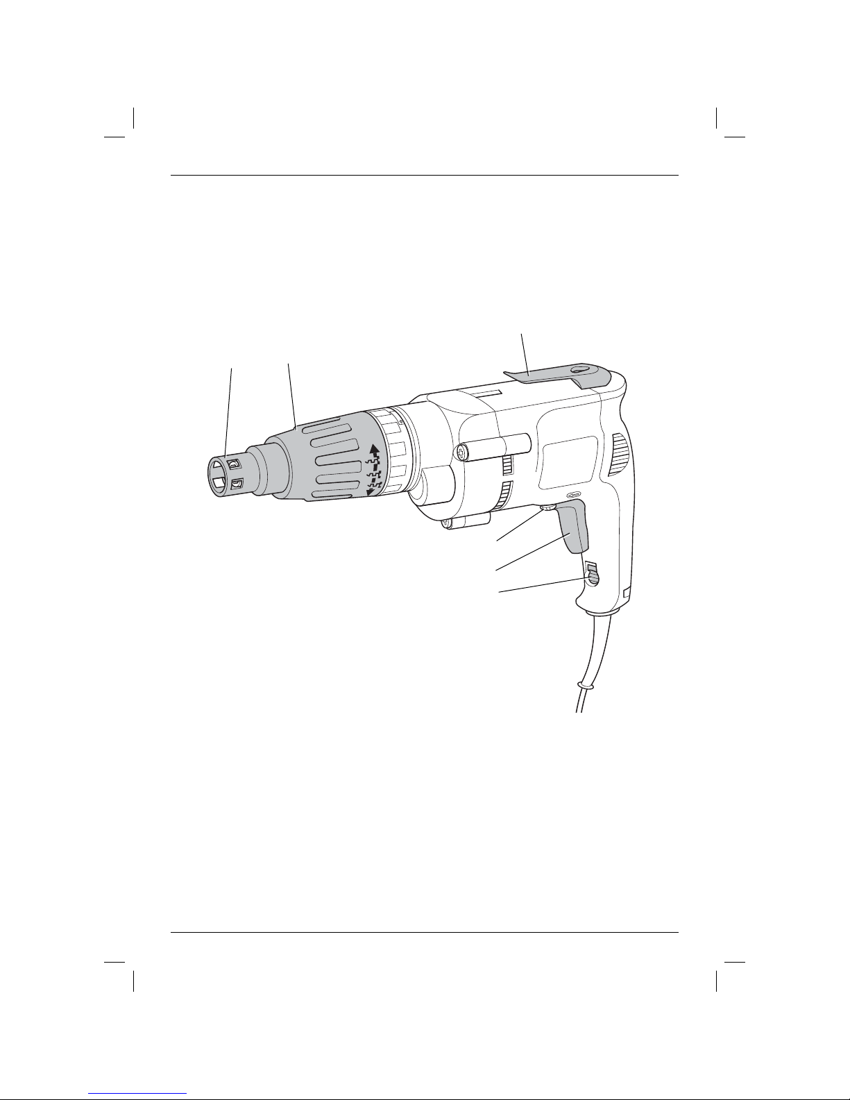
Figure 1
f
e
d
c
a
b
1
Page 3
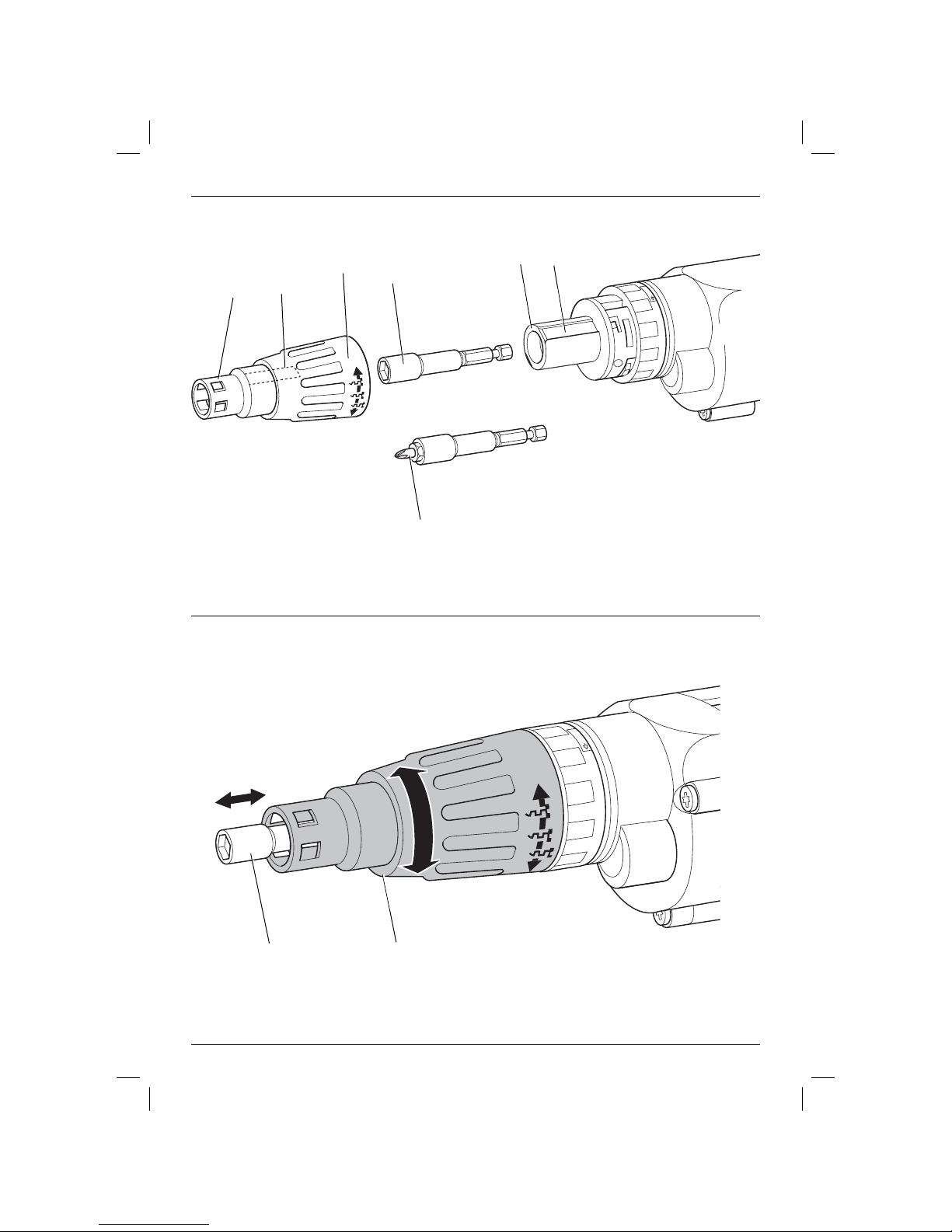
Figure 2
Figure 3
h
d
e
i
g
k
j
e
d
2
Page 4
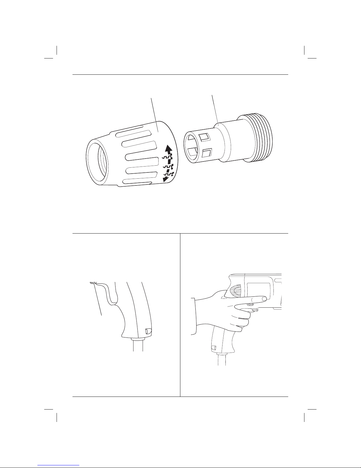
Figure 4
d
Figure 5 Figure 6
e
c
3
Page 5

ENGLISH
DRYWALL SCREWDRIVER
DW256/DW266/DW268/DW269
Congratulations!
You have chosen a DEWALT tool. Years of experience, thorough product development and innovation make
DEWALT one of the most reliable partners for professional power tool users.
Technical data
DW256 DW266 DW268 DW269
Voltage V 230 230 230 230
Power output W 540 540 540 540
No load speed min-1 0–4,000 0–2,500 0–2,500 0–1,000
Bit holder 1/4” hex 1/4” hex 1/4” hex 1/4” hex
Clutching method depth depth Versa Versa
sensitive sensitive clutch clutch
Weight kg 1.4 1.4 1.4 1.4
L
(sound pressure) dB(A)
pA
K
(sound pressure
PA
uncertainty) dB(A)
L
(acoustic power) dB(A)
WA
KWA (acoustic power
uncertainty) dB(A)
87
3
3
92
5.8
87 85 84
3 3
94 92 91
3.5 3.8 4.0
Vibration total values (triax vector sum) determined according to EN 60745:
Screwdriving without impact
a
= m/s² < 2.5 < 2.5 < 2.5 < 2.5
h
Uncertainty K = m/s² 1.5 1.5 1.5 1.5
The vibration emission level given in this information
sheet has been measured in accordance with a
standardised test given in EN 60745 and may be
used to compare one tool with another. It may be
used for a preliminary assessment of exposure.
WARNING: The declared vibration
emission level represents the main
applications of the tool. However if the
tool is used for different applications,
with different accessories or poorly
maintained, the vibration emission may
differ. This may significantly increase the
exposure level over the total working
period.
An estimation of the level of exposure to
vibration should also take into account
the times when the tool is switched off
or when it is running but not actually
doing the job. This may significantly
reduce the exposure level over the total
working period.
Identify additional safety measures to
protect the operator from the effects of
vibration such as: maintain the tool and
the accessories, keep the hands warm,
organisation of work patterns.
4
Page 6

ENGLISH
Defi nitions: Safety Guidelines
The definitions below describe the level of severity
for each signal word. Please read the manual and
pay attention to these symbols.
CAUTION: Used without the safety alert
Denotes risk of electric shock.
Denotes risk of fire.
DANGER: Indicates an imminently
hazardous situation which, if not avoided,
will result in death or serious injury.
WARNING: Indicates a potentially
hazardous situation which, if not
avoided, could result in death or
serious injury.
CAUTION: Indicates a potentially
hazardous situation which, if not
avoided, may result in minor or
moderate injury.
symbol indicates a potentially hazardous
situation which, if not avoided, may
result in property damage.
EC-Declaration of Conformity
DW256/DW266/DW268/DW269
DEWALT declares that these products described
under “technical data” have been designed in
compliance with:
98/37/EEC (until Dec. 28, 2009), 2004/108/EC,
2006/42/EC (from Dec. 29, 2009), 2006/95/EC;
EN 60745-1; EN60745-2-2; EN 55014-1;
EN 55014-2; EN 61000-3-2, EN61000-3-3.
For more information, please contact DEWALT at the
following address or refer to the back of the manual.
The undersigned is responsible for compilation of the
technical file and makes this declaration on behalf of
DEWALT.
Horst Grossmann
Vice President Engineering and Product
Development
DEWALT, Richard-Klinger-Straße 11,
D-65510, Idstein, Germany
16.10.08
WARNING: To reduce the risk of injury,
read the instruction manual.
General Power Tool Safety Warnings
WARNING! Read all safety warnings
The term “power tool” in the warnings refers
to your mains-operated (corded) power tool or
battery-operated (cordless) power tool.
1) WORK AREA SAFETY
a) Keep work area clean and well lit.
b) Do not operate power tools in explosive
c) Keep children and bystanders away while
2) ELECTRICAL SAFETY
a) Power tool plugs must match the outlet.
b) Avoid body contact with earthed or
c) Do not expose power tools to rain or wet
d) Do not abuse the cord. Never use the
e) When operating a power tool outdoors,
f) If operating a power tool in a damp
and instructions Failure to follow the
warnings and instructions may result in
electric shock, fire and/or serious injury.
SAVE ALL WARNINGS AND INSTRUCTIONS
FOR FUTURE REFERENCE
Cluttered or dark areas invite accidents.
atmospheres, such as in the presence of
flammable liquids, gases or dust. Power
tools create sparks which may ignite the dust
or fumes.
operating a power tool. Distractions can
cause you to lose control.
Never modify the plug in any way. Do
not use any adapter plugs with earthed
(grounded) power tools. Unmodified plugs
and matching outlets will reduce risk of
electric shock.
grounded surfaces such as pipes,
radiators, ranges and refrigerators. There
is an increased risk of electric shock if your
body is earthed or grounded.
conditions. Water entering a power tool will
increase the risk of electric shock.
cord for carrying, pulling or unplugging
the power tool. Keep cord away from
heat, oil, sharp edges or moving parts.
Damaged or entangled cords increase the
risk of electric shock.
use an extension cord suitable for outdoor
use. Use of a cord suitable for outdoor use
reduces the risk of electric shock.
location is unavoidable, use a residual
current device (RCD) protected supply.
Use of an RCD reduces the risk of electric
shock.
5
Page 7

ENGLISH
3) PERSONAL SAFETY
a) Stay alert, watch what you are doing and
use common sense when operating a
power tool. Do not use a power tool while
you are tired or under the influence of
drugs, alcohol or medication. A moment of
inattention while operating power tools may
result in serious personal injury.
b) Use personal protective equipment.
Always wear eye protection. Protective
equipment such as dust mask, non-skid
safety shoes, hard hat, or hearing protection
used for appropriate conditions will reduce
personal injuries.
c) Prevent unintentional starting. Ensure
the switch is in the off position before
connecting to power source and/or
battery pack, picking up or carrying the
tool. Carrying power tools with your finger
on the switch or energising power tools that
have the switch on invites accidents.
d) Remove any adjusting key or wrench
before turning the power tool on. A
wrench or a key left attached to a rotating
part of the power tool may result in personal
injury.
e) Do not overreach. Keep proper
footing and balance at all times. This
enables better control of the power tool in
unexpected situations.
f) Dress properly. Do not wear loose
clothing or jewellery. Keep your hair,
clothing and gloves away from moving
parts. Loose clothes, jewellery or long hair
can be caught in moving parts.
g) If devices are provided for the connection
of dust extraction and collection facilities,
ensure these are connected and properly
used. Use of dust collection can reduce
dust-related hazards.
4) POWER TOOL USE AND CARE
a) Do not force the power tool. Use the
correct power tool for your application.
The correct power tool will do the job
better and safer at the rate for which it
was designed.
b) Do not use the power tool if the switch
does not turn it on and off. Any power
tool that cannot be controlled with the switch
is dangerous and must be repaired.
c) Disconnect the plug from the power
source and/or the battery pack from
the power tool before making any
adjustments, changing accessories, or
storing power tools. Such preventive safety
measures reduce the risk of starting the
power tool accidentally.
d) Store idle power tools out of the reach
of children and do not allow persons
unfamiliar with the power tool or these
instructions to operate the power tool.
Power tools are dangerous in the hands of
untrained users.
e) Maintain power tools. Check for
misalignment or binding of moving parts,
breakage of parts and any other condition
that may affect the power tool’s operation.
If damaged, have the power tool repaired
before use. Many accidents are caused by
poorly maintained power tools.
f) Keep cutting tools sharp and clean.
Properly maintained cutting tools with sharp
cutting edges are less likely to bind and are
easier to control.
g) Use the power tool, accessories and
tool bits etc., in accordance with these
instructions taking into account the
working conditions and the work to
be performed. Use of the power tool for
operations different from those intended
could result in a hazardous situation.
5) SERVICE
a) Have your power tool serviced by a
qualified repair person using only identical
replacement parts. This will ensure that the
safety of the power tool is maintained.
Additional Specifi c Safety Rules for
Screwdrivers
• Hold power tool by insulated gripping
surface, when performing an operation
where the fastener may contact hidden
wiring or its own cord (bolt). Fasteners
contacting a "live" wire may make exposed
metal parts of the power "live" and could give
the operator an electric shock.
Residual Risks
In spite of the application of the relevant safety
regulations and the implementation of safety
devices, certain residual risks cannot be avoided.
These are:
– Impairment of hearing .
– Risk of personal injury due flying particles.
– Risk of burns due to accessories becoming hot
during operation.
– Risk of personal injury due to prolonged use.
– Risk of squeezing fingers when changing the
accessory.
6
Page 8

ENGLISH
– Health hazards caused by breathing dust
developed when working in concrete
and/or masonry.
Markings on Tool
The following pictograms are shown on the tool:
Read instruction manual
before use.
Package Contents
The package contains:
1 Pistol grip screwdriver DW266
or
1 Universal screwdriver DW268/DW269
or
1 Drywall screwdriver DW256
1 Kitbox (K-models only)
1 Instruction manual
1 Exploded drawing
• Check for damage to the tool, parts or
accessories which may have occurred during
transport.
• Take the time to thoroughly read and
understand this manual prior to operation.
Description (fi g. 1–5)
WARNING: Never modify the power
tool or any part of it. Damage or
personal injury could result.
a. Variable speed switch
b. Lock-on button
c. Forward/reverse slider
d. Depth adjustment collar (DW256/DW266)
Torque adjustment collar (DW268/DW269)
e. Depth locator (DW256/DW266)
Ball retainer (DW268/DW269)
f. Belt clip
DEAD SPINDLE DRIVE CLUTCH
This screwdriver is equipped with a dead spindle
feature; the spindle does not turn until the fastener is
pressed into the workpiece. This enables fasteners
to be placed onto the drive accessory of a running
screwdriver.
INTENDED USE
Your DW256 drywall screwdriver has been designed
for driving drywall fasteners through drywall board
into timber or metal framing studs.
Your DW256 features a silent clutch function.
Your DW266 screwdriver has been designed for
professional screwdriving applications and for use as
a nutsetter.
Your DW268/DW269 universal screwdriver has been
designed for professional screwdriving applications.
DO NOT use under wet conditions or in presence of
flammable liquids or gases.
These screwdrivers are professional power tools.
DO NOT let children come into contact with the
tool. Supervision is required when inexperienced
operators use this tool.
Electrical Safety
The electrical motor has been designed for one
voltage only. Always check that power supply
corresponds to the voltage on the rating plate.
Your DEWALT tool is double insulated in
accordance with EN 60745; therefore no
earth wire is required.
If the supply cord is damaged, it must be replaced
by a specially prepared cord available through the
DEWALT service organization.
ASSEMBLY AND ADJUSTMENTS
WARNING: To reduce the risk of
injury, turn unit off and disconnect
machine from power source before
installing and removing accessories,
before adjusting or changing set-ups
or when making repairs. Be sure the
trigger switch is in the OFF position. An
accidental start-up can cause injury.
Fitting and Removing 1/4" Hex Drive
Accessories
Your DEWALT screwdriver has a 1/4" hexagonal
drive system. The drive accessory is retained in the
holder by a ball and a spring which engages in a
groove in the accessory shank.
DW268/DW269 (FIG. 1)
1. Pull the ball retainer (e) to the front and hold it.
2. Insert the accessory.
3. Release the ball retainer.
DW256/DW266
(FIG. 2)
1. Remove the collar (d) by pulling it forward.
2. Select the required accessory (both models)
and matching depth locator (e) when using a
nutsetter (DW266).
7
Page 9

ENGLISH
3. To insert the accessory (g), e.g., a bit holder or
nutsetter, push it into the holder (h) until it snaps
in place. Tap it lightly if required.
4. To remove the accessory pull it out of the holder
using a pair of pliers.
5. Reinstall the collar (d) by aligning the ribs (i) on
the inside of the collar (d) with the grooves (j) in
the clutch housing and snap the collar in place.
REPLACING THE BIT TIP (FIG. 2)
Simply pull out the bit tip (k). A pair of pliers maybe
required.
Driving Depth (fi g. 3)
DW256/DW266
The depth sensitive feature offers the following
advantages:
– The selected driving depth is repeatable for
structural integrity.
– Screws with sealing washers are driven correctly
so that no leaks occur.
SETTING THE DRIVING DEPTH
The driving depth is determined by the position of
the depth locator (e) in relation to the bit or socket.
The symbols on the collar (d) indicate how to set the
driving depth.
• Turn the collar (d) clockwise to increase the
driving depth.
• Turn the collar (d) counterclockwise to decrease
the driving depth.
Using a Nutsetter
DW266
1. For screws with sealing washers, turn the collar
(d) until the end of the nutsetter is flush with the
end of the depth locator.
• If required, turn the collar until the nutsetter is
recessed approximately 2 mm into the depth
locator.
NOTE: ALWAYS refer to the screw
manufacturer’s specifications for the proper
sealing washer settings in different applications.
2. Drive a screw into a waste piece and check the
distance between the washer and the material.
3. Turn the collar (d) counterclockwise or clockwise
to decrease or increase the driving depth as
required.
4. Drive another screw and readjust the collar (d)
until the desired setting is achieved.
Depth Locator (fi g. 4)
DW266
This model is supplied with two depth locators (e) to
accommodate different bits, holders, sockets and
adaptors.
TO CHANGE DEPTH LOCATORS
• Pull the collar (d) assembly off the tool.
• Hold the depth locator (e) and unscrew the
collar (d).
• Replace the depth locator (e).
• To reassemble, proceed in reverse order.
Torque Adjustment Collar (fi g. 1)
DW268/DW269
This model allows setting the torque for a wide
range of screws.
• To increase the torque, turn the torque
adjustment collar (d) counterclockwise.
• To decrease the torque, turn the torque
adjustment collar (d) clockwise.
• Drive a screw into a waste piece and check if
the screw is properly fastened.
• If the clutch ratchets unexpectedly (for example
when a wood knot is encountered), simply
increase the pressure on the tool.
Forward/Reverse Switch
(fi g. 5)
WARNING: Always wait until the motor
has come to a complete stand still
before changing the direction of rotation.
Select the forward or reverse rotation by moving the
forward/reverse switch (c) in the direction indicated
by the arrows.
OPERATION
Instructions for Use
WARNING: Always observe the safety
instructions and applicable regulations.
Screwdriving or Nutsetting (fi g. 1)
1. Select the appropriate bit for the screw (or nut)
to be driven.
2. Select forward or reverse rotation as described
above.
8
Page 10

ENGLISH
DW266: For nutsetting, always use the correct
depth locator (e).
3. To run the tool, press the variable speed switch
(a). The pressure exerted on the variable speed
switch determines the tool speed.
NOTE: If necessary, press the lock-on button
(b) for continuous operation and release the
variable speed switch. The lock-on button
only works in full speed, forward and reverse
rotation.
To stop the tool in continuous operation, press
the switch briefly and release it.
4. To stop the tool, release the switch.
WARNING: ALWAYS turn the tool
off when work is finished and before
unplugging.
Holding the tool (fi g. 6)
• For best results, hold the screwdriver with the
hand directly in line with the fastener and press
the variable speed switch with the last one or
two fingers of the hand, as shown. This reduces
the chance of the screw slipping from the drive
accessory when pressure is applied.
• To drive the screw, place it on the bit or into
the socket, press the variable speed switch
and push the screw into the workpiece with a
smooth, continuous motion. When the screw
is seated, a buzzing sound will come from the
front of the tool to indicate that the clutch has
disengaged.
MAINTENANCE
Your DEWALT power tool has been designed to
operate over a long period of time with a minimum
of maintenance. Continuous satisfactory operation
depends upon proper tool care and regular cleaning.
WARNING: To reduce the risk of
injury, turn unit off and disconnect
machine from power source before
installing and removing accessories,
before adjusting or changing set-ups
or when making repairs. Be sure the
trigger switch is in the OFF position. An
accidental start-up can cause injury.
Cleaning
WARNING: Blow dirt and dust out of
WARNING: Never use solvents or
DW256
• Regularly remove drywall dust from the clutch
the main housing with dry air as often as
dirt is seen collecting in and around the
air vents. Wear approved eye protection
and approved dust mask when
performing this procedure.
other harsh chemicals for cleaning the
non-metallic parts of the tool. These
chemicals may weaken the materials
used in these parts. Use a cloth
dampened only with water and mild
soap. Never let any liquid get inside the
tool; never immerse any part of the tool
into a liquid.
housing using compressed air. To do so,
remove the depth locator and collar (d).
Optional Accessories
WARNING: Since accessories, other
Various types of 1/4" hex. bits, holders, sockets
andadaptors are available as an option.
Consult your dealer for further information on the
appropriate accessories.
than those offered by DEWALT, have
not been tested with this product, use
of such accessories with this tool could
be hazardous. To reduce the risk of
injury, only DEWALT, recommended
accessories should be used with this
product.
Protecting the Environment
Separate collection. This product must
not be disposed of with normal
household waste.
Should you find one day that your D
needs replacement, or if it is of no further use to you,
do not dispose of it with household waste. Make this
product available for separate collection.
EWALT product
Lubrication
Your power tool requires no additional lubrication.
9
Page 11

ENGLISH
Separate collection of used products
and packaging allows materials to be
recycled and used again. Re-use of
recycled materials helps prevent
environmental pollution and reduces
the demand for raw materials.
Local regulations may provide for separate collection
of electrical products from the household, at
municipal waste sites or by the retailer when you
purchase a new product.
D
EWALT provides a facility for the collection and
recycling of DEWALT products once they have
reached the end of their working life. To take
advantage of this service please return your product
to any authorised repair agent who will collect them
on our behalf.
You can check the location of your nearest
authorised repair agent by contacting your local
DEWALT office at the address indicated in this
manual. Alternatively, a list of authorised DEWALT
repair agents and full details of our after-sales
service and contacts are available on the Internet at:
www.2helpU.com.
GUARANTEE
• 30 DAY NO RISK
SATISFACTION GUARANTEE •
If you are not completely satisfied with
the performance of your D
simply return it within 30 days, complete as
purchased, to the point of purchase, for a full
refund or exchange. Proof of purchase must
be produced.
• ONE YEAR FREE SERVICE CONTRACT •
If you need maintenance or service for your
DEWALT tool, in the 12 months following
purchase, it will be undertaken free of charge
at an authorized DEWALT repair agent. Proof
of purchase must be produced. Includes
labour and spare parts for Power Tools.
Excludes accessories.
• ONE YEAR FULL WARRANTY •
If your DEWALT product becomes defective
due to faulty materials or workmanship within
12 months from the date of purchase, we
guarantee to replace all defective parts free of
charge or, at our discretion, replace the unit
free of charge provided that:
• The product has not been misused.
• Repairs have not been attempted by
unauthorized persons.
• Proof of purchase date is produced. This
guarantee is offered as an extra benefit
and is additional to consumers statutory
rights.
For the location of your nearest authorized
DEWALT repair agent, please use the
appropriate telephone number on the back of
this manual. Alternatively, a list of authorized
DEWALT repair agents and full details on our
after-sales service are available on the Internet
at www.2helpU.com.
EWALT tool,
10
Page 12

N020020 10/08
 Loading...