

Page 1

33
ENGLISH
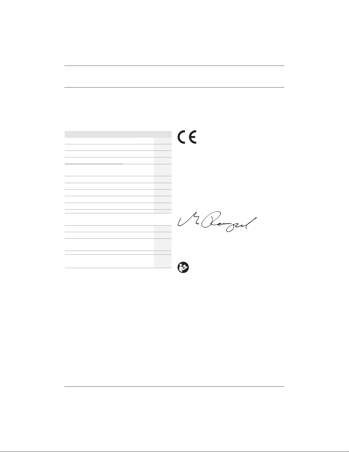
EC-Declaration of Conformity
Machinery Directive
Plunge Router
DCW600, DCW604
DEWALT declares that these products described under
Technical Data are in compliance with:
2006/42/EC, EN60745-1:2009 +A11:2010, EN60745-2-17:2010.
These products also comply with Directive 2014/30/EU and
2011/65/EU. For more information, please contact DEWALT at
the following address or refer to the back of themanual.
The undersigned is responsible for compilation of the technical
file and makes this declaration on behalf ofDEWALT.
Markus Rompel
Vice-President Engineering, PTE-Europa
DEWALT, Richard-Klinger-Straße 11,
D-65510, Idstein, Germany
15.03.2019
The vibration and/or noise emission level given in this
information sheet has been measured in accordance with
a standardised test given in EN60745 and may be used to
compare one tool with another. It may be used for a preliminary
assessment ofexposure.
!
WARNING: The declared vibration and/or noise emission
level represents the main applications of the tool. However
if the tool is used for different applications, with different
accessories or poorly maintained, the vibration and/or
noise emission may differ. This may significantly increase
the exposure level over the total workingperiod.
An estimation of the level of exposure to vibration and/
or noise should also take into account the times when the
tool is switched off or when it is running but not actually
doing the job. This may significantly reduce the exposure
level over the total workingperiod.
Identify additional safety measures to protect the
operator from the effects of vibration and/or noise such
as: maintain the tool and the accessories, keep the
hands warm (relevant for vibration), organisation of
workpatterns.
DCW600 DCW604
Voltage V
DC
18 18
Type 1 1
Battery type Li-Ion Li-Ion
Power output W 930 930
No-load speed rpm 16000–
25500
16000–
25500
Router carriag e 1 column 2 columns
Router carriag e stroke mm 55 55
Collet Size mm 8 8
Cutter Diamete r, max 30 30
Weight (withou t battery pack) kg 1.54 2.40
Noise and/or vibration values (triax vector sum) accordin g to EN60745-2-17:
LPA (emissio n sound pressure level ) dB(A) 73 73
LWA (sound power level) dB(A) 84 84
K (uncerta inty for the given sound
level)
dB(A) 3 3
Vibration emis sion value a
h
= m /s
2
4.7 4.7
Uncertainty K = m/s
2
2.7 2.7
Congratulations!
You have chosen a DEWALT tool. Years of experience, thorough
product development and innovation make DEWALT one of the
most reliable partners for professional power toolusers.
Technical Data
PLUNGE ROUTER
DCW600, DCW604
WARNING: To reduce the risk of injury, read the
instructionmanual.
Definitions: Safety Guidelines
The definitions below describe the level of severity for each
signal word. Please read the manual and pay attention to
thesesymbols.
!
DANGER: Indicates an imminently hazardous
situation which, if not avoided, will result in death or
seriousinjury.
!
WARNING: Indicates a potentially hazardous situation
which, if not avoided, could result in death or
seriousinjury.
!
CAUTION: Indicates a potentially hazardous situation
which, if not avoided, may result in minor or
moderateinjury.
NOTICE: Indicates a practice not related to
personal injury which, if not avoided, may result in
propertydamage.
!
Denotes risk of electricshock.
!
Denotes risk offire.
Page 2

34
ENGLISH
Batteries Chargers/Charge Times (Minutes)
Cat # V
DC
Ah Weight (kg)
DCB104 DCB 107 DCB112 DCB113 DC B115 DCB118 DCB132 DC B119
DCB546 18/54 6.0/2.0 1.05 60 270 170 140 90 60 90 X
DCB547 18/54 9.0/3.0 1.46 75* 420 270 220 135* 75* 135* X
DCB548 18/54 12.0/4.0 1.44 120 540 350 300 180 120 180 X
DCB181 18 1.5 0.35 22 70 45 35 22 22 22 45
DCB182 18 4.0 0.61 60/40** 185 120 100 60 60/40** 60 120
DCB183/B 18 2.0 0.40 30 90 60 50 30 3 0 30 60
DCB184/B 18 5.0 0.62 75/50** 240 150 120 75 75/50** 75 150
DCB185 18 1.3 0.35 22 60 40 30 22 22 22 X
DCB187 18 3.0 0.54 45 140 90 70 45 45 45 90
DCB189 18 4.0 0.54 60 185 120 100 60 60 60 120
*Date code 201811475B or la ter
**Date code 201536 or later
GENERAL POWER TOOL SAFETY WARNINGS
!
WARNING: Read all safety warnings, instructions,
illustrations and specifications provided with this
power tool. Failure to follow all instructions listed below
may result in electric shock, fire and/or serious injury.
SAVE ALL WARNINGS AND INSTRUCTIONS
FOR FUTURE REFERENCE.
The term “power tool” in the warnings refers to your mainsoperated (corded) power tool or battery-operated (cordless)
powertool.
1) Work Area Safety
a ) Keep work area clean and well lit. Cluttered or dark
areas inviteaccidents.
b ) Do not operate power tools in explosive
atmospheres, such as in the presence of flammable
liquids, gases or dust. Power tools create sparks which
may ignite the dust orfumes.
c ) Keep children and bystanders away while operating
a power tool. Distractions can cause you to losecontrol.
2) Electrical Safety
a ) Power tool plugs must match the outlet. Never
modify the plug in any way. Do not use any adapter
plugs with earthed (grounded) power tools.
Unmodified plugs and matching outlets will reduce risk of
electricshock.
b ) Avoid body contact with earthed or grounded
surfaces such as pipes, radiators, ranges and
refrigerators. There is an increased risk of electric shock if
your body is earthed orgrounded.
c ) Do not expose power tools to rain or wet conditions.
Water entering a power tool will increase the risk of
electricshock.
d ) Do not abuse the cord. Never use the cord for
carrying, pulling or unplugging the power tool. Keep
cord away from heat, oil, sharp edges or moving
parts. Damaged or entangled cords increase the risk of
electricshock.
e ) When operating a power tool outdoors, use an
extension cord suitable for outdoor use. Use of a cord
suitable for outdoor use reduces the risk of electricshock.
f ) If operating a power tool in a damp location is
unavoidable, use a residual current device (RCD)
protected supply. Use of an RCD reduces the risk of
electricshock.
3) Personal Safety
a ) Stay alert, watch what you are doing and use
common sense when operating a power tool. Do not
use a power tool while you are tired or under the
influence of drugs, alcohol or medication. A moment
of inattention while operating power tools may result in
serious personalinjury.
b ) Use personal protective equipment. Always wear
eye protection. Protective equipment such as dust mask,
non-skid safety shoes, hard hat or hearing protection used
for appropriate conditions will reduce personalinjuries.
c ) Prevent unintentional starting. Ensure the switch
is in the off-position before connecting to power
source and/or battery pack, picking up or carrying
the tool. Carrying power tools with your finger on the
switch or energising power tools that have the switch on
invitesaccidents.
d ) Remove any adjusting key or wrench before turning
the power tool on. A wrench or a key left attached
to a rotating part of the power tool may result in
personalinjury.
e ) Do not overreach. Keep proper footing and balance
at all times. This enables better control of the power tool
in unexpectedsituations.
f ) Dress properly. Do not wear loose clothing or
jewellery. Keep your hair and clothing away from
moving parts. Loose clothes, jewellery or long hair can be
caught in movingparts.
g ) If devices are provided for the connection of dust
extraction and collection facilities, ensure these are
connected and properly used. Use of dust collection
can reduce dust-relatedhazards.
Page 3

35
ENGLISH
Additional Specific Safety Rules for
Compact Routers
• Use clamps or another practical way to secure and
support the workpiece to a stable platform. Holding the
work by hand or against your body leaves it unstable and may
lead to loss ofcontrol.
• DO NOT cutmetal.
• Keep handles and gripping surfaces dry, clean, and
free from oil and grease. This will enable better control of
thetool.
• Maintain firm grip with both hands on the tool to resist
startingtorque. Maintain a firm grip on the tool at all times
whileoperating.
• Always follow the bit manufacturer’s speed
recommendations as some bit designs require specific
speeds for safety or performance. If you are unsure of the
proper speed or are experiencing any type of problem, contact
the bitmanufacturer.
• Keep hands away from cutting area. Never reach under
the workpiece for any reason. Keep the router base firmly in
contact with the workpiece whencutting.
• Never run the motor unit when it is not inserted in one of
the router bases. The motor is not designed to behandheld.
• Keep cutting pressure constant. Do not overloadmotor.
• Use sharp bits. Dull bits may cause the router to swerve or
stall underpressure.
• Be sure that the motor has stopped completely before
you lay the router down. If the bit is still spinning when the
tool is laid down, it could cause injury ordamage.
• Be sure that the router bit is clear of the workpiece
before starting the motor. If the bit is in contact with the
workpiece when the motor starts it could make the router
jump, causing damage orinjury.
h ) Do not let familiarity gained from frequent use of
tools allow you to become complacent and ignore
tool safety principles. A careless action can cause severe
injury within a fraction of asecond.
4) Power Tool Use and Care
a ) Do not force the power tool. Use the correct power
tool for your application. The correct power tool
will do the job better and safer at the rate for which it
wasdesigned.
b ) Do not use the power tool if the switch does not turn
it on and off. Any power tool that cannot be controlled
with the switch is dangerous and must berepaired.
c ) Disconnect the plug from the power source and/
or remove the battery pack, if detachable, from
the power tool before making any adjustments,
changing accessories, or storing power tools. Such
preventive safety measures reduce the risk of starting the
power toolaccidentally.
d ) Store idle power tools out of the reach of children
and do not allow persons unfamiliar with the power
tool or these instructions to operate the power tool.
Power tools are dangerous in the hands of untrainedusers.
e ) Maintain power tools and accesories. Check for
misalignment or binding of moving parts, breakage
of parts and any other condition that may affect the
power tool’s operation. If damaged, have the power
tool repaired before use. Many accidents are caused by
poorly maintained powertools.
f ) Keep cutting tools sharp and clean. Properly
maintained cutting tools with sharp cutting edges are less
likely to bind and are easier tocontrol.
g ) Use the power tool, accessories and tool bits, etc.
in accordance with these instructions, taking into
account the working conditions and the work to be
performed. Use of the power tool for operations different
from those intended could result in a hazardoussituation.
h ) Keep handles and grasping surfaces dry, clean and
free from oil and grease. Slippery handles and grasping
surfaces do not allow for safe handling and control of the
tool in unexpectedsituations.
5) Battery Tool Use and Care
a ) Recharge only with the charger specified by the
manufacturer. A charger that is suitable for one type
of battery pack may create a risk of fire when used with
another batterypack.
b ) Use power tools only with specifically designated
battery packs. Use of any other battery packs may create
a risk of injury andfire.
c ) When battery pack is not in use, keep it away from
other metal objects, like paper clips, coins, keys,
nails, screws or other small metal objects, that can
make a connection from one terminal to another.
Shorting the battery terminals together may cause burns
or afire.
d ) Under abusive conditions, liquid may be ejected
from the battery; avoid contact. If contact
accidentally occurs, flush with water. If liquid
contacts eyes, additionally seek medical help. Liquid
ejected from the battery may cause irritation orburns.
e ) Do not use a battery pack or tool that is damaged or
modified. Damaged or modified batteries may exhibit
unpredictable behaviour resulting in fire, explosion or risk
of injury.
f ) Do not expose a battery pack or tool to fire or
excessive temperature. Exposure to fire or temperature
above 130 °C may causeexplosion.
g ) Follow all charging instructions and do not charge
the battery pack or tool outside the temperature
range specified in the instructions. Charging
improperly or at temperatures outside the specified range
may damage the battery and increase the risk of fire.
6) Service
a ) Have your power tool serviced by a qualified repair
person using only identical replacement parts. This
will ensure that the safety of the power tool is maintained.
b ) Never service damaged battery packs. Service
of battery packs should only be performed by the
manufacturer or authorized service providers.
Page 4

36
ENGLISH
Residual Risks
In spite of the application of the relevant safety regulations
and the implementation of safety devices, certain residual risks
cannot be avoided. These are:
• Impairment ofhearing.
• Risk of personal injury due to flyingparticles.
• Risk of burns due to accessories becoming hot
duringoperation.
• Risk of personal injury due to prolongeduse.
SAVE THESE INSTRUCTIONS
• ALWAYS remove the battery before making adjustments
or changingbits.
• Keep hands clear of bits when motor is running to
prevent personalinjury.
• Never touch the bit immediately after use. It may be
extremelyhot.
• Provide clearance under workpiece for router bit when
through-cutting.
• Tighten collet nut securely to prevent the bit
fromslipping.
• Never tighten collet nut without abit.
• Do not use router bits with a diameter in excess of
30mm in thistool.
• Avoid climb-cutting (cutting in direction opposite than
shown in FigureO). Climb-cutting increases the chance
for loss of control resulting in possible injury. When
climb-cutting is required (backing around a corner), exercise
extreme caution to maintain control of router. Make smaller
cuts and remove minimal material with eachpass.
• Always use straight- cutters, rabbet-cutters, profile cutters,
slotter cutters or grooved knives with a shank diameter that
corresponds to the size of the collet i n yourtool.
• Always use bits s uitable for a speed of min. 30000 min-1 and
markedaccordingly.
• Do not hand-hold the router in an upside-down or
horizontal position. The motor can separate from the base if
not properly attached according to theinstructions.
• Before starting the motor clear the work area of all
foreignobjects.
• Do not use in a routertable.
• Always keep the chip shield (if included) clean and
inplace.
• Do not press spindle lock button while the motor is
running. Doing so can damage the spindlelock.
• Always make sure the work surface is free from nails and
other foreign objects. Cutting into a nail can cause the bit
and the tool tojump.
Chargers
DEWALT chargers require no adjustment and are designed to be
as easy as possible tooperate.
Electrical Safety
The electric motor has been designed for one voltage only.
Always check that the battery pack voltage corresponds to the
voltage on the rating plate. Also make sure that the voltage of
your charger corresponds to that of yourmains.
Your DEWALT charger is double insulated in
accordance with EN60335; therefore no earth wire
isrequired.
If the supply cord is damaged, it must be replaced by a
specially prepared cord available through the DEWALT
serviceorganisation.
Mains Plug Replacement
(U.K. & Ireland Only)
If a new mains plug needs to be fitted:
• Safely dispose of the oldplug.
• Connect the brown lead to the live terminal in theplug.
• Connect the blue lead to the neutralterminal.
!
WARNING: No connection is to be made to the
earthterminal.
Follow the fitting instructions supplied with good quality plugs.
Recommended fuse: 3A.
Using an Extension Cable
An extension cord should not be used unless absolutely
necessary. Use an approved extension cable suitable for
the power input of your charger (see Technical Data). The
minimum conductor size is 1mm2; the maximum length
is30m.
When using a cable reel, always unwind the cablecompletely.
Important Safety Instructions for All Battery
Chargers
SAVE THESE INSTRUCTIONS: This manual contains important
safety and operating instructions for compatible battery
chargers (refer to TechnicalData).
• Before using charger, read all instructions and cautionary
markings on charger, battery pack, and product using
batterypack.
!
WARNING: Shock hazard. Do not allow any liquid to get
inside charger. Electric shock mayresult.
!
WARNING: We recommend the use of a residual current
device with a residual current rating of 30mA orless.
!
CAUTION: Burn hazard. To reduce the risk of injury,
charge only DEWALT rechargeable batteries. Other types of
batteries may burst causing personal injury anddamage.
!
CAUTION: Children should be supervised to ensure that
they do not play with theappliance.
NOTICE: Under certain conditions, with the charger
plugged into the power supply, the exposed charging
contacts inside the charger can be shorted by foreign
material. Foreign materials of a conductive nature such
as, but not limited to, steel wool, aluminum foil or any
buildup of metallic particles should be kept away from
charger cavities. Always unplug the charger from the
Page 5

37
ENGLISH
power supply when there is no battery pack in the cavity.
Unplug charger before attempting to clean
• DO NOT attempt to charge the battery pack with any
chargers other than the ones in this manual. The charger
and battery pack are specifically designed to worktogether.
• These chargers are not intended for any uses other than
charging DEWALT rechargeable batteries. Any other uses
may result in risk of fire, electric shock orelectrocution.
• Do not expose charger to rain orsnow.
• Pull by plug rather than cord when disconnecting
charger. This will reduce risk ofdamage to electric plug
andcord.
• Make sure that cord is located so that it will not be
stepped on, tripped over, or otherwise subjected to
damage orstress.
• Do not use an extension cord unless it is absolutely
necessary. Use of improper extension cord could result in risk
of fire,electric shock, orelectrocution.
• Do not place any object on top of charger or place
the charger on a soft surface that might block the
ventilation slots and result in excessive internal heat.
Place the charger in a position away from any heat source. The
charger is ventilated through slots in the top and the bottom
of thehousing.
• Do not operate charger with damaged cord or plug—
have them replacedimmediately.
• Do not operate charger if it has received a sharp blow,
been dropped, or otherwise damaged in any way. Take it
to an authorised servicecentre.
• Do not disassemble charger; take it to an authorised
service centre when service or repair is required. Incorrect
reassembly may result in a risk of electric shock, electrocution
orfire.
• In case of damaged power supply cord the supply cord must
be replaced immedi ately by the manufacturer, its service agent
or similar qualified person to prevent anyhazard.
• Disconnect the charger from the outlet before
attempting any cleaning. This will reduce the risk of
electric shock. Removing the battery pack will not reduce
thisrisk.
• NEVER attempt to connect two chargerstogether.
• The charger is designed to operate on standard
230V household electrical power. Do not attempt to
use it on any other voltage. This does not apply to the
vehicularcharger.
Charging a Battery (Fig. C)
1. Plug the charger into an appropriate outlet before inserting
battery pack.
2. Insert the battery pack
1
into the charger, making sure the
battery pack is fully seated in the charger. The red (charging)
light will blink repeatedly indicating that the charging
process has started.
3. The completion of charge will be indicated by the red
light remaining ON continuously. The battery pack is fully
charged and may be used at this time or left in the charger.
To remove the battery pack from the charger, push the
battery release button
2
on the battery pack.
NOTE: To ensure maximum performance and life of lithium-ion
battery packs, charge the battery pack fully before first use.
Charger Operation
Refer to the indicators below for the charge status of the battery
pack.
Charge Indicat ors
Charging
Fully Charged
Hot/Cold Pack Delay*
* The red light will continue to blink, but a yellow indicator light
will be illuminated during this operation. Once the battery pack
has reached an appropriate temperature, the yellow light will
turn off and the charger will resume the charging procedure.
The compatible charger(s) will not charge a faulty battery pack.
The charger will indicate faulty battery by refusing to light.
NOTE: This could also mean a problem with a charger.
If the charger indicates a problem, take the charger and battery
pack to be tested at an authorised service centre.
Hot/Cold Pack Delay
When the charger detects a battery pack that is too hot or too
cold, it automatically starts a Hot/Cold Pack Delay, suspending
charging until the battery pack has reached an appropriate
temperature. The charger then automatically switches to the
pack charging mode. This feature ensures maximum battery
pack life.
A cold battery pack will charge at a slower rate than a warm
battery pack. The battery pack will charge at that slower rate
throughout the entire charging cycle and will not return to
maximum charge rate even if the battery pack warms.
The DCB118 charger is equipped with an internal fan designed
to cool the battery pack. The fan will turn on automatically
when the battery pack needs to be cooled. Never operate the
charger if the fan does not operate properly or if ventilation slots
are blocked. Do not permit foreign objects to enter the interior
of the charger.
Electronic Protection System
XR Li-Ion tools are designed with an Electronic Protection
System that will protect the battery pack against overloading,
overheating or deep discharge.
The tool will automatically turn off if the Electronic Protection
System engages. If this occurs, place the lithium-ion battery
pack on the charger until it is fully charged.
Wall Mounting
These chargers are designed to be wall mountable or to sit
upright on a table or work surface. If wall mounting, locate the
charger within reach of an electrical outlet, and away from a
corner or other obstructions which may impede air flow. Use
the back of the charger as a template for the location of the
mounting screws on the wall. Mount the charger securely using
Page 6

38
ENGLISH
drywall screws (purchased separately) at least 25.4mm long
with a screw head diameter of 7–9mm, screwed into wood to
an optimal depth leaving approximately 5.5mm of the screw
exposed. Align the slots on the back of the charger with the
exposed screws and fully engage them in the slots.
Charger Cleaning Instructions
!
WARNING: Shock hazard. Disconnect the charger
from the AC outlet before cleaning. Dirt and grease
may be removed from the exterior of the charger using a
cloth or soft non-metallic brush. Do not use water or any
cleaning solutions. Never let any liquid get inside the tool;
never immerse any part of the tool into a liquid.
Battery Packs
Important Safety Instructions for All Battery
Packs
When ordering replacement battery packs, be sure to include
catalogue number and voltage.
The battery pack is not fully charged out of the carton. Before
using the battery pack and charger, read the safety instructions
below. Then follow charging procedures outlined.
READ ALL INSTRUCTIONS
• Do not charge or use battery in explosive atmospheres,
such as in the presence of flammable liquids, gases or
dust. Inserting or removing the battery from the charger may
ignite the dust or fumes.
• Never force battery pack into charger. Do not modify
battery pack in any way to fit into a non-compatible
charger as battery pack may rupture causing serious
personal injury.
• Charge the battery packs only in DE WALT chargers.
• DO NOT splash or immerse in water or other liquids.
• Do not store or use the tool and battery pack in
locations where the temperature may reach or exceed
40 ˚C (104 ˚F) (such as outside sheds or metal buildings
in summer).
• Do not incinerate the battery pack even if it is severely
damaged or is completely worn out. The battery pack can
explode in a fire. Toxic fumes and materials are created when
lithium-ion battery packs are burned.
• If battery contents come into contact with the skin,
immediately wash area with mild soap and water. If
battery liquid gets into the eye, rinse water over the open eye
for 15 minutes or until irritation ceases. If medical attention
is needed, the battery electrolyte is composed of a mixture of
liquid organic carbonates and lithium salts.
• Contents of opened battery cells may cause respiratory
irritation. Provide fresh air. If symptoms persists, seek medical
attention.
!
WARNING: Burn hazard. Battery liquid may be flammable
if exposed to spark or flame.
!
WARNING: Never attempt to open the battery pack for
any reason. If battery pack case is cracked or damaged,
do not insert into charger. Do not crush, drop or damage
battery pack. Do not use a battery pack or charger that
has received a sharp blow, been dropped, run over or
damaged in any way (i.e., pierced with a nail, hit with
a hammer, stepped on). Electric shock or electrocution
may result. Damaged battery packs should be returned to
service centre for recycling.
!
WARNING: Fire hazard. Do not store or carry the
battery pack so that metal objects can contact
exposed battery terminals. For example, do not place
the battery pack in aprons, pockets, tool boxes, product kit
boxes, drawers, etc., with loose nails, screws, keys, etc.
!
CAUTION: When not in use, place tool on its side on
a stable surface where it will not cause a tripping
or falling hazard. Some tools with large battery packs
will stand upright on the battery pack but may be easily
knocked over.
Transportation
!
WARNING: Fire hazard. Transporting batteries can
possibly cause fire if the battery terminals inadvertently
come in contact with conductive materials. When
transporting batteries, make sure that the battery
terminals are protected and well insulated from materials
that could contact them and cause a short circuit.
NOTE: Lithium-ion batteries should not be put in
checkedbaggage.
DEWALT batteries comply with all applicable shipping
regulations as prescribed by industry and legal standards which
include UN Recommendations on the Transport of Dangerous
Goods; International Air Transport Association (IATA) Dangerous
Goods Regulations, International Maritime Dangerous Goods
(IMDG) Regulations, and the European Agreement Concerning
The International Carriage of Dangerous Goods by Road (ADR).
Lithium-ion cells and batteries have been tested to section 38.3
of the UN Recommendations on the Transport of Dangerous
Goods Manual of Tests and Criteria.
In most instances, shipping a DEWALT battery pack will be
excepted from being classified as a fully regulated Class 9
Hazardous Material. In general, only shipments containing a
lithium-ion battery with an energy rating greater than 100 Watt
Hours (Wh) will require being shipped as fully regulated Class 9.
All lithium-ion batteries have the Watt Hour rating marked on
the pack. Furthermore, due to regulation complexities, DEWALT
does not recommend air shipping lithium-ion battery packs
alone regardless of Watt Hour rating. Shipments of tools with
batteries (combo kits) can be air shipped as excepted if the Watt
Hour rating of the battery pack is no greater than 100 Whr.
Regardless of whether a shipment is considered excepted
or fully regulated, it is the shipper's responsibility to consult
the latest regulations for packaging, labeling/marking and
documentation requirements.
The information provided in this section of the manual is
provided in good faith and believed to be accurate at the time
the document was created. However, no warranty, expressed or
implied, is given. It is the buyer’s responsibility to ensure that its
activities comply with the applicable regulations.
Page 7
39
ENGLISH
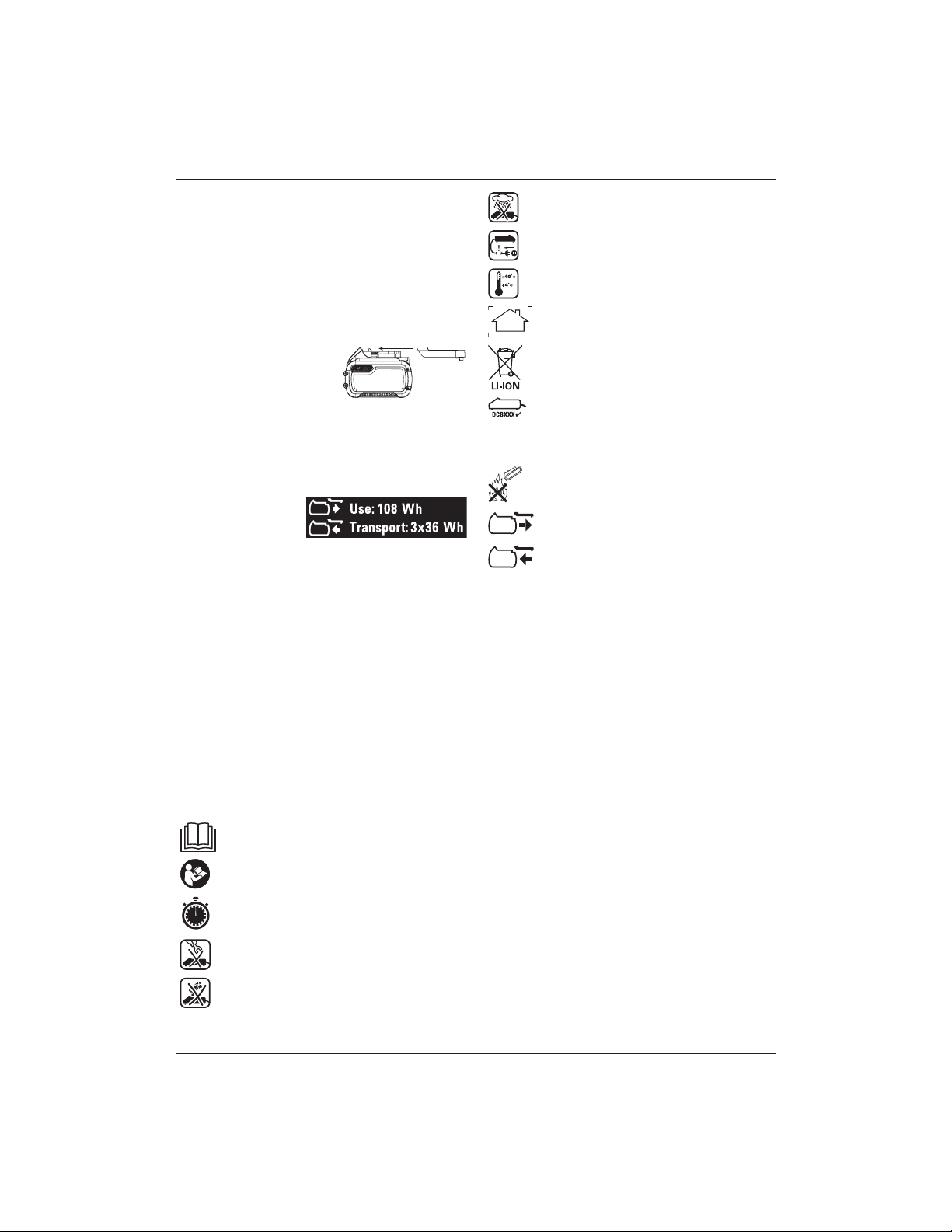
Transporting the FLEXVOLTTM Battery
The DEWALT FLEXVOLTTM battery has two modes: Use and
Transport.
Use Mode: When the FLEXVOLTTM battery stands alone or is in
a DEWALT 18V product, it will operate as an 18V battery. When
the FLEXVOLTTM battery is in a 54V or a 108V (two 54V batteries)
product, it will operate as a 54V battery.
Transport Mode: When the cap is attached to the FLEXVOLTTM
battery, the battery is in Transport mode. Keep the cap for
shipping.
When in Transport mode, strings
of cells are electrically
disconnected within the pack
resulting in 3 batteries with a
lower Watt hour (Wh) rating as compared to 1 battery with a
higher Watt hour rating. This increased quantity of 3 batteries
with the lower Watt hour rating can exempt the pack from
certain shipping regulations that are imposed upon the higher
Watt hour batteries.
For example, the Transport
Wh rating might indicate
3x36 Wh, meaning 3
batteries of 36 Wh each.
The Use Wh rating might
indicate 108Wh (1battery implied).
Storage Recommendations
1. The best storage place is one that is cool and dry away
from direct sunlight and excess heat or cold. For optimum
battery performance and life, store battery packs at room
temperature when not in use.
2. For long storage, it is recommended to store a fully charged
battery pack in a cool, dry place out of the charger for
optimal results.
NOTE: Battery packs should not be stored completely depleted
of charge. The battery pack will need to be recharged before
use.
Labels on Charger and Battery Pack
In addition to the pictographs used in this manual, the labels
on the charger and the battery pack may show the following
pictographs:
Read instruction manual before use.
See Technical Data for charging time.
Do not probe with conductive objects.
Do not charge damaged battery packs.
Example of Use and Transport Label Marking
Battery Type
The DCW600, DCW604 operate on a 18 volt battery pack.
These battery packs may be used: DCB181, DCB182, DCB183,
DCB183B, DCB184, DCB184B, DCB185, DCB187, DCB189,
DCB546, DCB547, DCB548. Refer to Technical Data for
moreinformation.
Package Contents
The package contains:
DCW600
1 Router with fixed base
1 Fixed base dust collection
1 Basic parallel fence
1 Collet 8 mm
1 Collet 1/4"
1 Wrench
1 Round subbase
DCW604
1 Router with fixed base and plunge base
1 Round subbase
1 Plunge base dust collection
1 Fixed base dust collection
1 Basic parallel fence
1 Plunge base parallel fence
1 Collet 8 mm
1 Collet 1/4"
1 Wrench
1 Centreing tool
Do not expose to water.
Have defective cords replaced immediately.
Charge only between 4 ˚C and 40 ˚C.
Only for indoor use.
Discard the battery pack with due care for the
environment.
Charge DEWALT battery packs only with designated
DEWALT chargers. Charging battery packs other
than the designated DEWALT batteries with a
DEWALT charger may make them burst or lead to
other dangerous situations.
Do not incinerate the battery pack.
USE (without transport cap). Example: Wh rating
indicates 108 Wh (1 battery with 108 Wh).
TRANSPORT (with built-in transport cap). Example:
Wh rating indicates 3 x 36 Wh (3batteries of 36 Wh).
Page 8
40
ENGLISH
Description (Fig. A)
!
WARNING: Never modify the power tool or any part of it.
Damage or personal injury couldresult.
1
Battery pack
2
Battery release button
3
On/Off switch
4
Variable speed dial
5
Depth adjustment ring
6
Motor
7
Spindle lock button
8
Spindle
9
Guide pin groove
10
Worklights
11
Micro-adjustment scale
12
Locking lever
13
D-shaped subbase
14
Turret stop
15
Depth adjustment rod
16
Plunge lock lever
17
Guide pins
18
Plunge base side handles
19
Motor stop
20
Plunge subbase
21
Round subbase
Intended Use
This tool is designed for professional medium-duty routing of
wood, wood products and plastics with 6–8 mm shankbits.
Inserting and Removing the Battery Pack
from the Tool (Fig. C)
NOTE: Make sure your battery pack
1
is fullycharged.
To Install the Battery Pack into the Tool Handle
1. Align the battery pack
1
with the rails inside the tool’s
handle (Fig. C).
2. Slide it into the handle until the battery pack is firmly seated
in the tool and ensure that you hear the lock snap intoplace.
To Remove the Battery Pack from the Tool
1. Press the release button
2
and firmly pull the battery pack
out of the toolhandle.
2. Insert battery pack into the charger as described in the
charger section of thismanual.
Fuel Gauge Battery Packs (Fig. C)
Some DEWALT battery packs include a fuel gauge which
consists of three green LED lights that indicate the level of
charge remaining in the batterypack.
To actuate the fuel gauge, press and hold the fuel gauge
button
46
. A combination of the three green LED lights will
illuminate designating the level of charge left. When the level
of charge in the battery is below the usable limit, the fuel gauge
will not illuminate and the battery will need to berecharged.
NOTE: The fuel gauge is only an indication of the charge left on
the battery pack. It does not indicate tool functionality and is
subject to variation based on product components, temperature
and end-userapplication.
Date Code Position (Fig. C)
The date code
22
, which also includes the year of manufacture,
is printed into thehousing.
Example:
2019 XX XX
Year of Manufacture
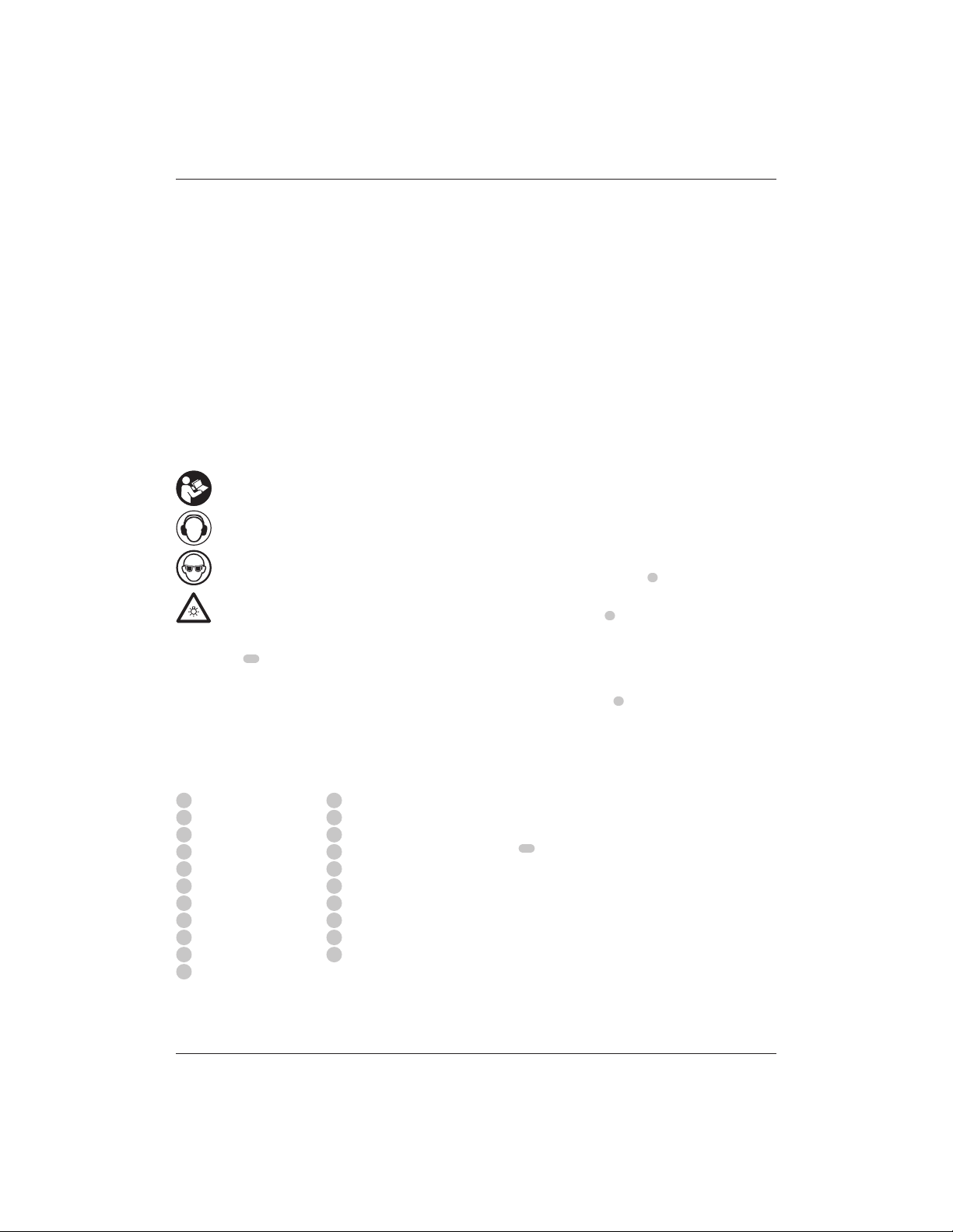
Markings on Tool
The following pictograms are shown on the tool:
Read instruction manual before use.
Wear ear protection.
Wear eye protection.
Visible radiation. Do not stare into light.
1 Li-Ion battery pack (C1, D1, L1, M1, P1, S1, T1, X1, Y1 models)
2 Li-Ion battery packs (C2, D2, L2, M2, P2, S2, T2, X2, Y2 models)
3 Li-Ion battery packs (C3, D3, L3, M3, P3, S3, T3, X3, Y3 models)
1 Instruction manual
NOTE: Battery packs, chargers and kitboxes are not included
with N models. Battery packs and chargers are not included with
NT models. Bmodels include Bluetooth® batterypacks.
NOTE: The Bluetooth® word mark and logos are registered
trademarks owned by the Bluetooth®, SIG, Inc. and any use of
such marks by DEWALT is under license. Other trademarks and
trade names are those of their respectiveowners.
• Check for damage to the tool, parts or accessories which may
have occurred duringtransport.
• Take the time to thoroughly read and understand this manual
prior tooperation.
DO NOT use under wet conditions or in the presence of
flammable liquids orgases.
DO NOT let children come into contact with the tool.
Supervision is required when inexperienced operators use
thistool.
• Young children and the infirm. This appliance is not
intended for use by young children or infirm persons
without supervision.
• This product is not intended for use by persons (including
children) suffering from diminished physical, sensory or
mental abilities; lack of experience, knowledge or skills
unless they are supervised by a person responsible for their
safety. Children should never be left alone with thisproduct.
ASSEMBLY AND ADJUSTMENTS
!
WARNING: To reduce the risk of serious personal
injury, turn tool off and disconnect battery pack
before making any adjustments or removing/
installing attachments or accessories. An accidental
start-up can causeinjury.
!
WARNING: Use only DEWALT battery packs andchargers.
Bit Installation and Removal (Fig. D)
To Install the Bit
1. Remove the motor unit from the base unit. Refer to
Removing the Motor from the Fixed Base or Removing
Page 9

41
ENGLISH
the Motor from the Plunge Base (ifneeded).
2. Clean and insert the round shank of the desired router bit
into the loosened collet as far as it will go and then pull it
out about 1.6mm.
3. Depress the spindle lock button
7
to hold the spindle shaft
in place while turning the collet nut
23
clockwise with the
wrenchprovided.
NOTE: The unit is equipped with multiple spindle lock
detents allowing an optional "manual ratchet" method of
tightening thebit.
To tighten with the "manual ratchet" method:
a. Without removing the wrench from the collet nut
23
,
release pressure on the spindle lock button
7
.
b. With the wrench still on the collet nut, reverse the
tightening direction to reset the wrenchposition.
c. Depress the spindle lock button again and turn the
wrenchclockwise.
d. Repeat the procedure until the collet nut reaches
desiredtightness.
NOTICE: Avoid possible damage to the collet. Never
tighten the collet without abit.
To Remove the Bit
1. Remove the motor unit from the base unit (refer to
Removing the Motor from the Fixed Base or Removing
the Motor from the Plunge Base.
2. Depress the spindle lock button
7
to hold the spindle shaft
in place while turning the collet nut
23
anticlockwise with
the wrenchprovided.
To loosen using the "manual ratchet" method:
1. Without removing the wrench from the collet nut
23
,
release pressure on the spindle lock button
7
.
2. With the wrench still on the collet nut
23
, reverse the
loosening direction to reset the wrenchposition.
3. Depress the spindle lock button
7
again and turn the
wrenchanticlockwise.
4. Repeat the procedure until the collet nut
23
is loose and
the bit can beremoved.
Collets
NOTE: Never tighten the collet without first installing a router
bit in it. Tightening an empty collet, even by hand, can damage
thecollet.
To change collet sizes, unscrew the collet assembly as described
above. Install the desired collet by reversing the procedure.
The collet and the collet nut are connected. Do not attempt to
remove the collet from the colletnut.
Locking Lever Adjustment (Fig. E)
Excessive force should not be used to clamp the locking lever.
Using excessive force may damage thebase.
When the locking lever is clamped, the motor should not move
in thebase.
Adjustment is needed if the locking lever will not clamp without
excessive force or if the motor moves in the base afterclamping.
To adjust the locking lever’s clamping force:
1. Open the locking lever
12
(fixed base) or
40
(plungebase).
2. Using a hex wrench turn locking lever adjustment screw
24
in smallincrements.Turning the screw clockwise tightens
the lever, while turning the screw anticlockwise loosens
thelever.
Centreing the Subbase (Fig. A, F1–F3)
If you need to adjust, change, or replace a subbase, a centreing
tool is recommended. The centreing tool consists of a cone and
apin.
To adjust a subbase, follow the stepsbelow.
Figure F1 shows adjusting the D-shaped subbase on the
fixed base.
Figure F2 shows adjusting the subbase on the plungebase.
Figure F3 shows adjusting the round subbase on the fixed base.
1. Loosen but do not remove the subbase screws
25
so the
subbase movesfreely.
2. Insert the pin into the collet and tighten the colletnut.
3. Insert the motor into the base and clamp the locking
lever
12
/
40
on thebase.
4. Place the cone on the pin and lightly press down on the
cone until it stops. This will centre thesubbase.
5. While holding down on the cone, tighten the
subbasescrews.
Using Template Guides
The plunge subbase will accept template guides. On the
fixed base, the round subbase will be needed to accept
templateguides.
NOTE: The D-shaped subbase does not accommodate template
guides and is designed to accommodate cutters up to 30mm
indiameter.
To Use Template Guides
1. Install template guide to subbase using two screws and
tightensecurely.
2. Centre the subbase. Refer to Centreing theSubbase.
Installing a Fixed Base Parallel Fence (Fig. G)
A parallel fence (model DE6913) for your fixed base isincluded.
1. Remove the motor from the fixed base. Refer to Removing
the Motor from the FixedBase.
2. Remove flat head screws
27
from storage holes on
parallelfence.
3. Slide parallel fence
26
into parallel fence slot
28
on side of
fixed base (Fig.G). Insert the two flat head screws through
the appropriate holes in the subbase to secure the edge
guide. Tightenhardware.
4. Follow all instructions included with the parallelfence.
NOTE: To remove the parallel fence, reverse the above
procedure. After removing parallel fence always replace the two
flat head screws
27
into the storage holes on the parallel fence
to preventloss.
Page 10

42
ENGLISH
Installing a Plunge Base Parallel Fence with
Guide Rods, DCW604 Only (Fig. H)
A parallel fence with guide rods may be included with your
plunge base unit. A premium parallel fence (model DE6913)
is also available from your local retailer or service centre at
extracost.
1. Attach the guide rods
36
to the plunge routerbase.
2. Attach the thumb screws
37
and springs
38
to thebase.
3. Tighten the thumb screws
37
.
4. Slide the parallel fence
39
over therods.
5. Attach thumb screws
37
and springs
38
to the
parallelfence.
6. Tighten the thumb screws temporarily. Refer to Adjusting
the ParallelFence.
Adjusting the Parallel Fence (Fig.A, H)
Follow the assembly instructions included with the
parallelfence.
1. Draw a cutting line on thematerial.
2. Lower the router carriage until the cutter is in contact with
theworkpiece.
3. Lock the plunge mechanism by releasing the plunge lock
lever
16
4. Position the router on the cutting line. The outer cutting
edge of the cutter must coincide with the cuttingline.
5. Slide the parallel fence
39
against the workpiece and
tighten the thumb screws
37
.
Attaching a Dust Extraction System to the
Fixed Base (Fig. I)
To connect the router to a dust extraction system for dust
collection, follow these steps:
1. Remove the motor unit from the base. Refer to Removing
the Motor from the FixedBase.
2. Attach dust extraction system attachment accessory
29
to the base as shown. Tighten thumb screws
30
securely
byhand.
3. Attach hose adapter to dust extraction system
attachmentaccessory.
4. When using dust extraction system attachment, be aware
of the placement of the dust extraction system. Be sure that
the dust extraction system is stable and that its hose will not
interfere with thework.
Attaching a Dust Extraction System to the
Plunge Base, DCW604 Only (Fig. J)
1. Remove the motor unit from the base. Refer to Removing
the Motor from the PlungeBase.
2. Slide tab
31
(inset) on dust extraction system
attachment
35
into slot in plunge base and snap tab
32
(inset) into hole in plungebase.
3. Secure to base with supplied plastic washer
33
and thumb
screw
34
. Tighten thumb screw securely byhand.
4. Attach hose adaptor to dust extraction systemattachment.
When using dust extraction system attachment, be aware of
the placement of the dust extraction system. Be sure the dust
extraction system is stable and its hose will not interfere with
thework.
Set-Up: Fixed Base (Fig. A, K, L)
Inserting the Motor into the Fixed Base
1. Open the locking lever
12
on thebase.
2. If the depth adjustment ring
5
is not on the motor
6
,
thread the depth adjustment ring onto the motor until the
ring is about halfway between the top and bottom of the
motor as shown. Insert the motor into the base by aligning
the groove on the motor
6
with the guide pins
17
on the
base. Slide the motor down until the depth adjustment ring
snaps intoplace.
NOTE: Guide pin grooves
9
are located on either side of
the motor so it can be positioned in twoorientations.
3. Adjust the depth of cut by turning the depth adjustment
ring. Refer to Adjusting the Depth ofCut.
4. Close the locking lever
12
when the desired depth is
achieved. For information on setting the cutting depth, refer
to Adjusting the Depth ofCut.
Adjusting the Depth of Cut (Fig.L)
1. Open the locking lever
12
and turn the depth adjustment
ring
5
until the bit just touches the work piece. Turning
the ring clockwise raises the cutting head while turning it
anticlockwise lowers the cuttinghead.
2. Turn the micro-adjustment scale
11
clockwise until the 0
on the scale lines up with the pointer on the bottom of the
depth adjustmentring.
3. Turn the depth adjustment ring until the pointer lines up
with desired depth of cut marking on the micro-adjustment
scale
11
.
NOTE: Each mark on the adjustment scale represents a
depth change of 0.4 mm and one full (360º) turn of the ring
changes the depth 12.7mm.
4. Close the locking lever
12
to lock thebase.
Removing the Motor from the Fixed Base (Fig.K)
1. Remove the battery pack from the motor. Refer to Installing
and Removing the BatteryPack.
2. Open the locking lever
12
on thebase.
3. Grasp the motor unit with one hand, depressing both quick
release tabs
45
.
4. With the other hand, grasp the base and pull motor from
thebase.
Set-Up: Plunge Base, DCW604 Only
(Fig. A, M)
Inserting the Motor into the Plunge Base
1. Remove the depth adjustment ring
5
from the motor
6
. It
is not used with the plungebase.
NOTE:Snap depth adjustment ring onto fixed base, when
not in use, to preventloss.
Page 11

43
ENGLISH
2. Open the plunge base locking lever
40
.
3. Making sure the spindle lock button is facing front, insert the
motor
6
into the base by aligning the groove on the motor
with the guide pins
17
on the base. Slide the motor down
until the motor stops on the motor stop
19
.
4. Close the locking lever
40
.
Adjusting the Plunge Routing Depth (Fig.M)
!
WARNING: Laceration hazard. Do not change the
turret stop while the router is running. This will place
your hands too near the cutterhead.
!
WARNING: To prevent loss of control, ALWAYS
tighten the travel-limiting nuts together. Inadvertent
movement could prevent full bitretraction.
!
WARNING: To prevent loss of control, set the travellimiting nuts so that bit can be retracted into the
base of the router, clear of theworkpiece.
!
WARNING: To reduce the risk of injury, NEVER adjust
or remove the stop nut. Motor can disengage resulting
in loss ofcontrol.
!
CAUTION: Turn the router on before plunging the
cutter head into theworkpiece.
1. Unlock the plunge mechanism by pulling down the plunge
lock lever
16
. Gently push down on the two handes to
plunge the router down as far as it will go, allowing the bit
to just touch theworkpiece.
2. Lock the plunge mechanism by releasing the plunge lock
lever
16
.
3. Loosen the depth adjustment rod
15
by turning the thumb
screw
41
anticlockwise.
4. Slide the depth adjustment rod
15
down so that it meets
the lowest turret stop
14
.
5. Slide the zero adjuster tab
42
on the depth adjustment
rod down so that the top of it meets zero on the depth
adjustment scale
43
.
6. Grasping the top, knurled section of the depth adjustment
rod
15
, slide it up so that the tab
42
aligns with the
desired depth of cut on the depth adjustment scale
43
.
7. Tighten the thumb screw
41
to hold the depth adjustment
rod inplace.
8. Keeping both hands on the handles, unlock the plunge
mechanism by pulling the plunge lock lever
16
down. The
plunge mechanism and the motor will move up. When
the router is plunged, the depth adjustment rod will hit
the turret stop, allowing the router to reach exactly the
desireddepth.
Using the Rotating Turret for Stepped Cuts
(Fig.M)
If the depth of cut required is more than is acceptable in a single
pass, rotate the turret so that depth rod
15
lines up with taller
turret stop initially. After each cut, rotate the turret so that the
depth stop lines up with shorter post until the final depth of cut
isreached.
When using the fixed base, one hand should be on top of the
battery and the other hand around the fixed base (Fig.N1).
When using the plunge base, grasp the side handles firmly as
shown in Fig.N2.
Starting and Stopping the Motor (Fig. A)
!
CAUTION: Before starting the tool, clear the work area
of all foreign objects. Also keep firm grip on tool to resist
startingtorque.
!
CAUTION: To avoid personal injury and/or damage to
finished work, always allow the power unit to come to a
COMPLETE STOP before putting the tooldown.
To turn unit on, depress the side of the dust-protected switch
3
that reads “ON” and corresponds to the symbol “I.” To turn the
unit off, depress the side of the switch that reads “OFF” and
corresponds with the symbol “O.”
Proper Hand Position (Fig. N1, N2)
!
WARNING: To reduce the risk of serious personal injury,
ALWAYS use proper hand position asshown.
!
WARNING: To reduce the risk of serious personal
injury, ALWAYS hold securely in anticipation of a
suddenreaction.
OPERATION
Instructions for Use
!
WARNING: Always observe the safety instructions and
applicableregulations.
!
WARNING: To reduce the risk of serious personal
injury, turn tool off and disconnect battery pack
before making any adjustments or removing/
installing attachments or accessories. An accidental
start-up can cause injury.
!
WARNING: Do not change the turret stop while the
router is running. This will place your hands too near the
cutterhead.
Fine Adjustment of Routing Depth (Fig.M)
The knurled knob
44
at the bottom end of the depth
adjustment rod can be used to make minoradjustments.
1. To decrease the cutting depth, rotate the knob clockwise
(looking down from the top of therouter).
2. To increase the cutting depth, rotate the knob anticlockwise
(looking down from the top of therouter).
NOTE: One complete rotation of the knob results in a change of
about 1 mm indepth.
Removing the Motor from the PlungeBase
(Fig.M)
1. Remove the battery pack from the motor. Refer to Installing
and Removing the BatteryPack.
2. Open the locking lever
40
on thebase.
3. Grasp the motor unit with one hand and the base with the
other hand, pull motor from theplungebase.
Page 12

44
ENGLISH
Cutting with the Fixed Base (Fig. C)
Set up the router to use the fixed base by following the
instructions in the Assembly and Adjustmentssection.
After the router is set-up, install the battery pack as shown
in Fig.C, then set your router speed (refer to Choosing
RouterSpeed).
NOTE: Always feed the router opposite to the direction in which
the cutter isrotating.
Cutting with the Plunge Base, DCW604 Only
(Fig. A)
NOTE: The depth of cut is locked in the plunge base's default
state. The plunge lock requires user actuation to enable the
"release to lock" plungemechanism.
1. Depress the plunge lock lever
16
and plunge the router
down until the bit reaches the setdepth.
2. Release the plunge lock lever
16
when desired depth
isreached.
NOTE: Releasing the plunge lock lever automatically locks
the motor inplace.
NOTE: If additional resistance is needed, use the hand to
depress the plunge locklever.
NOTE: If additional clamping strength is required, press the
lock lever further to tighten in the clockwisedirection.
3. Perform thecut.
4. Depressing the plunge lock lever will disable the locking
mechanism allowing the router bit to disengage from
theworkpiece.
5. Turn the routeroff.
Direction of Feed (Fig. O)
The direction of feed is very important when routing and can
make the difference between a successful job and a ruined
project. The figures show the proper direction of feed for some
typical cuts. A general rule to follow is to move the router in
a anticlockwise direction on an outside cut and a clockwise
direction on an insidecut.
Shape the outside edge of a piece of stock by following
these steps:
1. Shape the end grain, left toright.
2. Shape the straight grain side moving left toright.
3. Cut the other end grainside.
4. Finish the remaining straight grainedge.
Choosing Router Speed (Fig. A)
Refer to the Speed Selection Chart to choose a router speed.
Turn the variable speed dial
4
to control routerspeed.
Soft Start Feature
The compact routers are equipped with electronics to provide
a soft start feature that minimizes the start up torque of
themotor.
MAINTENANCE
Your power tool has been designed to operate over a long
period of time with a minimum of maintenance. Continuous
satisfactory operation depends upon proper tool care and
regularcleaning.
!
WARNING: To reduce the risk of serious personal
injury, turn tool off and disconnect battery pack
before making any adjustments or removing/
installing attachments or accessories. An accidental
start-up can cause injury.
The charger and battery pack are notserviceable.
Lubrication
Your power tool requires no additionallubrication.
Variable Speed Control (Fig.A)
This router is equipped with a variable speed dial
4
with 7
speeds between 16000 and 25500 RPM. Adjust the speed by
turning the variable speed dial
4
.
NOTICE: In low and medium speed operation, the speed
control prevents the motor speed from decreasing. If you
expect to hear a speed change and continue to load the
motor, you could damage the motor by overheating.
Reduce the depth of cut and/or slow the feed rate to
prevent tooldamage.
The compact routers are equipped with electronics to monitor
and maintain the speed of the tool whilecutting.
SPEED SELECTION CHART*
DIAL SETTING APPROX. RPM APPLICATION
1 16000
Large diameter bits and cutters2 17500
3 19100
4 20700
Small diameter bits and cutters.
Softwoods, pla stics, laminates.
5 22300
6 23900
7 25500
*The speeds in this chart are approximate and are fo r reference only. Your
router may not exactly produce th e speed listed for the dial setting.
NOTE: Make several light passes instead of one heavy pass for
better qualitywork.
Worklights (Fig. A)
The worklights
10
are located at the front of the motor
6
. To
turn on the worklight, switch on the on/off switch
3
. Worklights
will remain on 20 seconds after the on/off switch is moved to
the off position.
NOTE: The worklights are for lighting the immediate work
surface and are not intended to be used as aflashlight.
NOTE: If worklights flash, check the charge on the battery; it
could be low. If they still flash with a charged battery, the unit
should be taken to a service centre forevaluation.
Page 13

45
ENGLISH
Cleaning
!
WARNING: Blow dirt and dust out of the main housing
with dry air as often as dirt is see n collecting in and around
the air vents. Wear approved eye protection and approved
dust mask when performing thisprocedure.
!
WARNING: Never use solvents or other harsh chemicals
for cleaning the non-metallic parts of the tool. These
chemicals may weaken the materials used in these parts.
Use a cloth dampened only with water and mild soap.
Never let any liquid get inside the tool; never immerse any
part of the tool into aliquid.
Waxing Motor and Base
To maintain a smooth action when moving the motor unit in
relation to the base, the outside of the motor unit and the inside
of the base can be waxed using any standard paste or liquid
wax. Per the manufacturers instructions, rub the wax onto the
outside diameter of the motor unit and the inside diameter of
the base. Allow wax to dry and buff off residue with a softcloth.
Optional Accessories
!
WARNING: Since accessories, other than those offered
by DEWALT, have not been tested with this product, use
of such accessories with this tool could be hazardous.
To reduce the risk of injury, only DEWALT recommended
accessories should be used with thisproduct.
Consult your dealer for further information on the
appropriateaccessories.
Protecting the Environment
Separate collection. Products and batteries marked
with this symbol must not be disposed of with normal
householdwaste.
Products and batteries contain materials that can
be recovered or recycled reducing the demand for raw
materials. Please recycle electrical products and batteries
according to local provisions. Further information is available at
www.2helpU.com.
Rechargeable Battery Pack
This long life battery pack must be recharged when it fails
to produce sufficient power on jobs which were easily done
before. At the end of its technical life, discard it with due care for
our environment:
• Run the battery pack down completely, then remove it from
the tool.
• Li-Ion cells are recyclable. Take them to your dealer or a
local recycling station. The collected battery packs will be
recycled or disposed of properly.
Page 14
46
ESPAÑOL
vibraciones, como, por ejemplo, realizar el mantenimiento
de la herramienta y de los accesorios, mantener las manos
calientes (relevante para las vibraciones) u organizar
patrones de trabajo.
El nivel de emisión de vibraciones y/o ruido que figura en esta
hoja de información se ha medido de conformidad con una
prueba normalizada proporcionada en la EN60745 y puede
utilizarse para comparar una herramienta con otra. Puede usarse
para una evaluación preliminar de la exposición.
!
ADVERTENCIA: El nivel de emisión de vibraciones y ruido
declarado representa las principales aplicaciones de la
herramienta. Sin embargo, si se utiliza la herramienta
para otras aplicaciones, con accesorios diferentes o mal
mantenidos, la emisión de ruido y vibraciones puede
variar. Esto puede aumentar considerablemente el nivel de
exposición durante el período total de trabajo.
Para valorar el nivel de exposición al ruido y a las
vibraciones, también deberían tenerse en cuenta las veces
que la herramienta está apagada o en funcionamiento
pero sin realizar ningún trabajo. Esto puede reducir
considerablemente el nivel de exposición durante el
periodo total de trabajo.
Identifique medidas de seguridad adicionales para
proteger al operador de los efectos del ruido y las
¡Enhorabuena!
Ha elegido una herramienta DEWALT. Años de experiencia,
innovación y un exhaustivo desarrollo de productos hacen que
DEWALT sea una de las empresas más fiables para los usuarios
de herramientas eléctricasprofesionales.
Datos técnicos
FRESADORA INALÁMBRICA SIN ESCOBILLAS
DCW600, DCW604
DCW600 DCW604
Voltaje V
DC
18 18
Tipo 1 1
Tipo de bat ería Li-Ion Li-Ion
Potencia de salida W 930 930
Velocidad en vacío
rpm 16000–
25500
16000–
25500
Soporte de la fresadora
1 columna 2 columnas
Carrera del soporte de la fresado ra
mm 55 55
Tamaño del mandril
mm 8 8
Diámetro máxim o de las fresas
mm 30 30
Peso (sin p aquete de batería) kg 1,54 2,40
Valores de ruido y/o valores de vibración (suma vector es triaxiales) de acue rdo
con EN60745-2- 17:
LPA (nivel de presión sonora d e emisión) dB(A) 73 73
LWA (nivel de potencia sonora) dB(A) 84 84
K (incertidumbre para el nivel de
sonido dado)
dB(A) 3 3
Valor de la emisión de vibración a
h
= m/s24,7 4,7
Incertidumbre K = m/s
2
2,7 2,7
Declaración de Conformidad CE
Directriz de la Maquinaria
Directriz de la Maquinaria
DCW600, DCW604
DEWALT declara que los productos descritos bajo Datos
técnicos son conformes a las normas:
2006/42/CE, EN60745-1:2009+A11:2010, EN60745-2-17:2010.
Estos productos también son conformes con las Directivas
2014/30/UE y 2011/65/UE. Si desea más información,
póngase en contacto con DEWALT en la dirección indicada a
continuación o bien consulte la parte posterior de estemanual.
El que suscribe es responsable de la compilación del archivo
técnico y realiza esta declaración en representación deDEWALT.
Markus Rompel
Vicepresidente de Ingeniería, PTE-Europa
DEWALT, Richard-Klinger-Strase 11,
D-65510, Idstein, Alemania
15.03.2019
ADVERTENCIA: para reducir el riesgo de lesiones, lea el
manual deinstrucciones.
Definiciones: normas de seguridad
Las siguientes definiciones describen el nivel de gravedad de las
señales. Lea el manual y preste atención a estossímbolos.
!
PELIGRO: indica una situación de peligro inminente, que
si no se evita, provocará la muerte o lesionesgraves.
!
ADVERTENCIA: indica una situación de posible peligro
que, si no se evita, podría provocar la muerte o
lesionesgraves.
!
ATENCIÓN: indica una situación de posible peligro
que, si no se evita, puede provocar lesiones leves
omoderadas.
AVISO: Indica una práctica no relacionada con
las lesiones personales que, de no evitarse, puede
ocasionar dañosmateriales.
!
Indica riesgo de descargaeléctrica.
!
Indica riesgo deincendio.
 Loading...