

Page 1

If you have questions or comments, contact us.
Pour toute question ou tout commentaire, nous contacter.
Si tiene dudas o comentarios, contáctenos.
1-800-4-DeWALT
Instruction Manual
Guide D’utilisation
Manual de instrucciones
DCST920
20V Max* Lithium String Trimmer
Taille-bordureau lithium-ion de 20V max.*
Podadora de cuerda con batería de iones de litio de 20V Máx*
final page size: 8.5 x 5.5 in
Page 2

ENGLISH
English (original instructions) 1
Français (traduction de la notice d’instructions originale) 13
Español (traducido de las instrucciones originales) 26
Page 3
ENGLISH
DeWALT
DeWALT
Definitions: Safety Alert Symbols and Words
This instruction manual uses the following safety alert symbols and words to alert you to hazardous situations and your risk
of personal injury or propertydamage.
DANGER: Indicates an imminently hazardous situation which, if not avoided, will result in death or
seriousinjury.
WARNING: Indicates a potentially hazardous situation which, if not avoided, could result in death or
seriousinjury.
CAUTION: Indicates a potentially hazardous situation which, if not avoided, may result in minor or
moderateinjury.
(Used without word) Indicates a safety relatedmessage.
NOTICE: Indicates a practice not related to personal injury which, if not avoided, may result in
propertydamage.
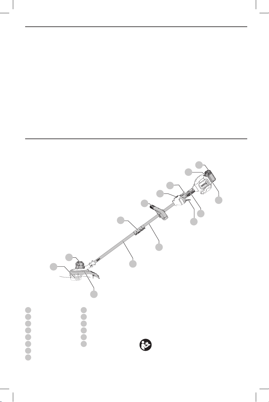
Fig. A
12
13
2
3
4
8
1
11
14
10
1
Variable speed trigger
2
Lock-off lever
3
Speed control switch
4
Auxiliary handle
5
Motor housing
6
Upper trimmer pole
7
Lower trimmer pole
8
Pole bracket
6
5
7
9
9
Guard
10
Spool housing
11
Battery housing
12
Battery pack
13
Battery release button
14
Handle
WARNING! Read all safety warnings
and all instructions. Failure to follow the warnings
and instructions may result in electric shock, fire and/
or seriousinjury.
WARNING: To reduce the risk of injury,
read the instructionmanual.
If you have any questions or comments about this or
any
1-800-4-
tool, call us toll free at:
(1-800-433-9258).
1
Page 4

ENGLISH
DeWALT
DeWALT
Important Safety Warnings
WARNING: To reduce risk of injury:
• Before any use, be sure everyone using this unit
reads and understands all safety instructions and
other information contained in this manual.
• Save these instructions and reviewfrequently.
WARNING: When using electric
gardening appliances, basic safety precautions should
always be followed to reduce risk of fire, electric shock,
and personal injury, including thefollowing.
READ ALL INSTRUCTIONS
1 . Avoid Dangerous Environments – DO NOT use
appliances in damp or wet locations. DO NOT operate
portable electric appliances in gaseous or explosive
atmospheres. Motors in these appliances normally spark,
and the sparks might ignitefumes.
2 . Don’t Use InRain.
3 . Keep All Bystanders Away – at a safe distance from
work area, especiallychildren.
4 . Dress Properly – Do not wear loose clothing or
jewelry. They can be caught in moving parts. Gloves and
substantial rubber soled footwear are recommended
when working outdoors. Wear protective hair covering to
contain longhair.
5 . Always Wear Eye Protection – Wear ANSI Z87.1
approved eye protection at all times when battery is
installed. Also use face or dust mask. Safety glasses are
available at extra cost at your local
or authorized service facility.
6 . Use Right Appliance – Do not use appliance for any job
except that for which it isintended.
7 . Avoid Accidentally Starting – Don’t carry with finger
ontrigger when battery isinstalled.
8 . Don’t Force Appliance – It will do the job better and
with less likelihood of a risk of injury at the rate for which
it wasdesigned.
9 . Don’t Overreach – Keep proper footing and balance at
alltimes.
10 . Stay Alert – Watch what you are doing. Use common
sense. DO NOT operate while under the influence of
alcohol or drugs, or when you are tired or ill.
11 . Disconnect Appliance – Remove the battery when not in
use, before servicing, when changing accessories such as
blades, and thelike.
12 . Store Idle Appliances Indoors – When not in use,
appliances should be stored indoors in dry, and high or
locked-up place – out of reach ofchildren.
13 . Maintain Appliance With Care – Keep cutting edge
sharp and clean for best performance and to reduce
the risk of injury. Follow instructions for lubricating and
changing accessories. Inspect appliance cord periodically,
and if damaged, have it repaired by an authorized service
facility. Inspect extension cords periodically and replace
2
Service Center
if damaged. Keep handles dry, clean, and free from oil
andgrease.
14 . Check Damaged Parts – Before further use of the
appliance, a guard or other part that is damaged should
be carefully checked to determine that it will operate
properly and perform its intended function. Check for
alignment of moving parts, binding of moving parts,
breakage of parts, mounting, and any other condition
that may affect its operation. A guard or other part that is
damaged should be properly repaired or replaced by an
authorized service center unless indicated elsewhere in
thismanual.
15 . Damage to Unit – If you strike or become entangled
with a foreign object, stop appliance immediately, remove
battery, check for damage and have any damage repaired
before further operation isattempted.
16 . Guard – Do not use this appliance without guard
attached. Keep guards in place and in workingorder.
17 . DO NOT immerse appliance in water or squirt it with a
hose. DO NOT allow any liquid to get inside it. If appliance
does get wet, allow to dry for a minimum of 48hours.
18 . DO NOT store the appliance on or adjacent to fertilizers
orchemicals.
19 . DO NOT clean with a pressurewasher.
20 . DO NOT charge appliance in rain, or in wetlocations.
Specific Warnings for String Trimmers
WARNING: This product is not an edger
and is not intended to be used foredging.
• Don’t operate the appliance when barefoot or wearing
open sandals.
• Wear heavy long pants to protect yourlegs.
• MAKE SURE that other persons and pets are at least
100 feet (30m)away.
• Keep face, hands and feet clear of rotating nylon line at
alltimes.
• The rotating line performs a cutting function. Use care
when trimming around screens and desirableplantings.
• To reduce the risk of rebound (ricochet) injury, work going
away from any nearby solid object such as wall, steps,
large stone, tree, etc. Use great care when working close to
solid objects and where necessary, do trimming byhand.
Additional Safety Warnings
CAUTION: Use only
spools and line. Using any other manufacturer's line
can reduce performance, damage the trimmer or
cause personalinjury.
Your trimmer uses 0.080 inches (2.032 mm) diameter
line. Do not use other size lines. This can degrade
performance, cause damage to the unit orinjury.
WARNING: Do not use appliance if the
switch trigger does not turn the appliance on or off.
Any appliance that can not be controlled with the
switch trigger is dangerous and must berepaired.
replacement
Page 5

WARNING: Some dust created by
DeWALT
DeWALT
this product contains chemicals known to the
State of California to cause cancer, birth defects or
other reproductive harm. Some examples of these
chemicalsare:
• compounds in fertilizers
• compounds in insecticides, herbicides
andpesticides
• arsenic and chromium from chemically
treatedlumber
To reduce your exposure to these chemicals, wear approved
safety equipment such as dust masks that are specially
designed to filter out microscopicparticles.
The label on your appliance may include the following
symbols. The symbols and their definitions are asfollows:
V ......................... volts
Hz ....................... hertz
min ..................... minutes
or DC ......direct current
...................... Class I Construction
(grounded)
…/min .............. per minute
BPM .................... beats per minute
IPM ..................... impacts per minute
RPM .................... revolutions per
minute
sfpm ................... surface feet per
minute
SPM .................... strokes per minute
A ......................... amperes
W ........................ watts
or AC ........... alternating current
or AC/DC .... alternating or
direct current
...................... Class II
Construction
(double insulated)
no ....................... no load speed
n ......................... rated speed
...................... earthing terminal
..................... safety alert symbol
..................... visible radiation
..................... wear respiratory
protection
..................... wear eye
protection
..................... wear hearing
protection
..................... read all
documentation
• Do not charge or use the battery pack in explosive
atmospheres, such as in the presence of flammable
liquids, gases or dust. Inserting or removing the battery
pack from the charger may ignite the dust orfumes.
• NEVER force the battery pack into the charger. DO
NOT modify the battery pack in any way to fit into
a non-compatible charger as battery pack may
rupture causing serious personal injury. Consult
the chart at the end of this manual for compatibility of
batteries andchargers.
• Charge the battery packs only in designated
• DO NOT splash or immerse in water or otherliquids.
• Do not store or use the tool and battery pack in
• Do not incinerate the battery pack even if it is
• If battery contents come into contact with the skin,
• Contents of opened battery cells may cause
chargers.
locations where the temperature may reach or
exceed 104°F (40°C) (such as outside sheds or metal
buildings in summer). For best life store battery packs in
a cool, drylocation.
NOTE: Do not store the battery packs in a tool with
the trigger switch locked on. Never tape the trigger
switch in the ONposition.
severely damaged or is completely worn out. The
battery pack can explode in a fire. Toxic fumes and
materials are created when lithium ion battery packs
areburned.
immediately wash area with mild soap and water. If
battery liquid gets into the eye, rinse water over the open
eye for 15 minutes or until irritation ceases. If medical
attention is needed, the battery electrolyte is composed of
a mixture of liquid organic carbonates and lithiumsalts.
respiratory irritation. Provide fresh air. If symptoms
persist, seek medicalattention.
ENGLISH
BATTERIES AND CHARGERS
The battery pack is not fully charged out of the carton.
Before using the battery pack and charger, read the
safety instructions below and then follow charging
proceduresoutlined. When ordering replacement battery
packs, be sure to include the catalog number andvoltage.
Your tool uses a
instructions before using your charger. Consult the chart
at the end of this manual for compatibility of chargers and
batterypacks.
READ ALL INSTRUCTIONS
charger. Be sure to read all safety
Important Safety Instructions for All
Battery Packs
WARNING: Read all safety warnings
and all instructions for the battery pack, charger
and power tool. Failure to follow the warnings
and instructions may result in electric shock, fire
and/or seriousinjury.
WARNING: Burn hazard. Battery liquid
may be flammable if exposed to spark orflame.
WARNING: Fire hazard. Never attempt
to open the battery pack for any reason. If the battery
pack case is cracked or damaged, do not insert into
the charger. Do not crush, drop or damage the battery
pack. Do not use a battery pack or charger that has
received a sharp blow, been dropped, run over or
damaged in any way (e.g., pierced with a nail, hit
with a hammer, stepped on). Damaged battery packs
should be returned to the service center forrecycling.
Transportation
WARNING: Fire hazard. Do not store
or carry the battery pack so that metal objects
can contact exposed battery terminals. For
example, do not place the battery pack in aprons,
pockets, tool boxes, product kit boxes, drawers, etc.,
with loose nails, screws, keys, etc. Transporting
batteries can possibly cause fires if the battery
terminals inadvertently come in contact with
3
Page 6
ENGLISH
DeWALT
DeWALT
DeWALT
DeWALT
DeWALT
DeWALT
conductive materials such as keys, coins,
hand tools and the like. The US Department of
Transportation Hazardous Material Regulations (HMR)
actually prohibit transporting batteries in commerce
or on airplanes in carry-on baggage UNLESS they
are properly protected from short circuits. So when
transporting individual battery packs, make sure that
the battery terminals are protected and well insulated
from materials that could contact them and cause a
shortcircuit.
Shipping the
The DeWALT FLEXVOLT™ battery has two modes:
Use and Shipping.
Use Mode: When the FLEXVOLT™ battery stands alone or is
in a DeWALT 20V Max* product, it will operate as a 20V Max*
battery. When the FLEXVOLT™ battery is in a 60V Max* or a
120V Max* (two 60V Max* batteries) product, it will operate
as a 60V Max* battery.
Shipping Mode: When
the cap is attached to the
FLEXVOLT™ battery, the
battery is in Shipping Mode.
Strings of cells are electrically
disconnected within the pack resulting in three batteries
with a lower Watt hour (Wh) rating as compared to one
battery with a higher Watt hour rating. This increased
quantity of three batteries with the lower Watt hour rating
can exempt the pack from certain shipping regulations that
are imposed upon the higher Watt hourbatteries.
The battery label indicates two Watt hour ratings (see
example). Depending on how the battery is shipped, the
appropriate Watt hour rating must be used to determine
the applicable shipping requirements. If utilizing the
shipping cap, the pack will be considered 3 batteries at
the Watt hour rating indicated for “Shipping”. If shipping
without the cap or in a tool, the pack will be considered one
battery at the Watt hour rating indicated next to “Use”.
Example of Use and Shipping Label Marking
For example, Shipping Wh rating might indicate 3 x 40 Wh,
meaning 3 batteries of 40 Watt hours each. The Use Wh
rating might indicate 120 Wh (1 batteryimplied).
FLEXVOLT™ Battery
USE: 120 Wh Shipping: 3 x 40 Wh
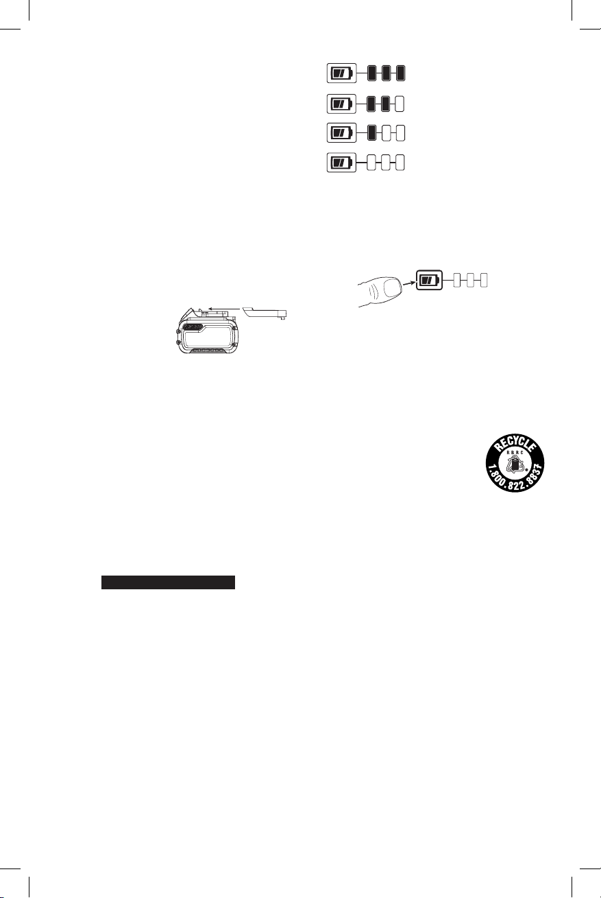
Fuel Gauge Battery Packs (Fig. B)
Some
consists of three green LED lights that indicate the level of
charge remaining in the batterypack.
The fuel gauge is an indication of approximate levels of
charge remaining in the battery pack according to the
followingindicators:
battery packs include a fuel gauge which
75–100% charged
51–74% charged
< 50% charged
Pack needs to be charged
To actuate the fuel gauge, press and hold the fuel gauge
button. A combination of the three green LED lights will
illuminate designating the level of charge left. When the
level of charge in the battery is below the usable limit, the
fuel gauge will not illuminate and the battery will need to
berecharged.
NOTE: The fuel gauge is only an indication of the charge left
on the battery pack. It does not indicate tool functionality
and is subject to variation based on product components,
temperature and end-userapplication.
For more information regarding fuel gauge battery packs,
please call 1-800-4website www.dewalt.com.
Fig. B
(1-800-433-9258) or visit our
The RBRC® Seal
The RBRC® (Rechargeable Battery
Recycling Corporation) Seal on the nickel
cadmium, nickel metal hydride or lithiumion batteries (or battery packs) indicates
that the costs to recycle these batteries
(or battery packs) at the end of their useful life have already
been paid by
spent nickel cadmium, nickel metal hydride or lithium-ion
batteries in the trash or municipal solid waste stream and
the Call2Recycle® program provides an environmentally
consciousalternative.
Call 2 Recycle, Inc., in cooperation with
battery users, has established the program in the United
States and Canada to facilitate the collection of spent nickel
cadmium, nickel metal hydride or lithium-ion batteries. Help
protect our environment and conserve natural resources by
returning the spent nickel cadmium, nickel metal hydride
or lithium-ion batteries to an authorized
center or to your local retailer for recycling. You may also
contact your local recycling center for information on
where to drop off the spent battery. RBRC® is a registered
trademark of Call 2 Recycle,Inc.
. In some areas, it is illegal to place
and other
service
Important Safety Instructions for All
Battery Chargers
WARNING: Read all safety warnings
and all instructions for the battery pack, charger
and power tool. Failure to follow the warnings
and instructions may result in electric shock, fire
and/or seriousinjury.
4
Page 7
• DO NOT attempt to charge the battery pack with
DeWALT
DeWALT
any chargers other than the ones in this manual.
The charger and battery pack are specifically designed to
worktogether.
• These chargers are not intended for any uses other
than charging
Any other uses may result in risk of fire, electric shock
orelectrocution.
• Do not expose the charger to rain orsnow.
• Pull by the plug rather than the cord when
disconnecting the charger. This will reduce the risk of
damage to the electric plug andcord.
• Make sure that the cord is located so that it will not
be stepped on, tripped over or otherwise subjected
to damage orstress.
• Do not use an extension cord unless it is absolutely
necessary. Use of improper extension cord could result in
risk of fire, electric shock orelectrocution.
• When operating a charger outdoors, always provide
a dry location and use an extension cord suitable
for outdoor use. Use of a cord suitable for outdoor use
reduces the risk of electricshock.
• An extension cord must have adequate wire size
(AWG or American Wire Gauge) for safety. The smaller
the gauge number of the wire, the greater the capacity
of the cable, that is, 16 gauge has more capacity than 18
gauge. An undersized cord will cause a drop in line voltage
resulting in loss of power and overheating. When using
more than one extension to make up the total length,
be sure each individual extension contains at least the
minimum wire size. The following table shows the correct
size to use depending on cord length and nameplate
ampere rating. If in doubt, use the next heavier gauge. The
lower the gauge number, the heavier thecord.
Minimum Gauge for Cord Sets
Volts
120 V 25 (7.6) 50 (15.2) 100 (30.5) 150 (45.7)
240 V 50 (15.2) 100 (30.5) 200 (61.0) 300 (91.4)
Ampere Rating
More
Not
Than
More
Than
0 6 18 16 16 14
6 10 18 16 14 12
10 12 16 16 14 12
12 16 14 12 Not Recommended
• Do not place any object on top of the charger or
place the charger on a soft surface that might block
the ventilation slots and result in excessive internal
heat. Place the charger in a position away from any heat
source. The charger is ventilated through slots in the top
and the bottom of thehousing.
• Do not operate the charger with a damaged cord
orplug.
• Do not operate the charger if it has received a sharp
blow, been dropped or otherwise damaged in any
way. Take it to an authorized servicecenter.
rechargeable batteries.
Total Length of Cord in Feet
(meters)
American Wire Gauge
ENGLISH
• Do not disassemble the charger; take it to an
authorized service center when service or repair
is required. Incorrect reassembly may result in a risk of
electric shock, electrocution orfire.
• Disconnect the charger from the outlet before
attempting any cleaning. This will reduce the risk of
electric shock. Removing the battery pack will not reduce
thisrisk.
• NEVER attempt to connect 2 chargerstogether.
• The charger is designed to operate on standard
120V household electrical power. Do not attempt to
use it on any other voltage. This does not apply to the
vehicularcharger.
WARNING:Shock hazard. Do not allow
any liquid to get inside the charger. Electric shock
mayresult.
WARNING: Burn hazard. Do not
submerge the battery pack in any liquid or allow any
liquid to enter the battery pack. Never attempt to open
the battery pack for any reason. If the plastic housing
of the battery pack breaks or cracks, return to a service
center forrecycling.
CAUTION: Burn hazard. To reduce the risk
of injury, charge only
packs. Other types of batteries may overheat and burst
resulting in personal injury and propertydamage.
NOTICE: Under certain conditions, with the charger
plugged into the power supply, the charger can
be shorted by foreign material. Foreign materials
of a conductive nature, such as, but not limited to,
grinding dust, metal chips, steel wool, aluminum
foil or any buildup of metallic particles should be
kept away from the charger cavities. Always unplug
the charger from the power supply when there is no
battery pack in the cavity. Unplug the charger before
attempting toclean.
rechargeable battery
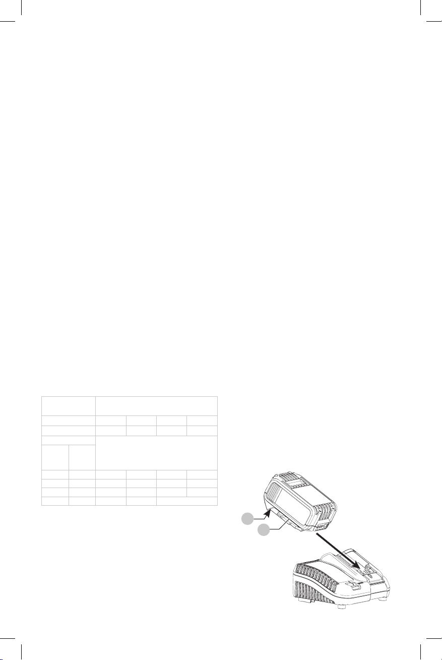
Charging a Battery (Fig. C)
1. Plug the charger into an appropriate outlet before
inserting batterypack.
Fig. C
12
13
5
Page 8
ENGLISH
2. Insert the battery pack
the battery pack is fully seated in the charger. The red
(charging) light will blink continuously indicating that
the charging process hasstarted.
3. The completion of charge will be indicated by the red
light remaining ON continuously. The battery pack is
fully charged and may be used at this time or left in the
charger. To remove the battery pack from the charger,
push the battery release button
NOTE: To ensure maximum performance and life of lithiumion battery packs, charge the battery pack fully before
firstuse.
13
into the charger, making sure
12
on the batterypack.
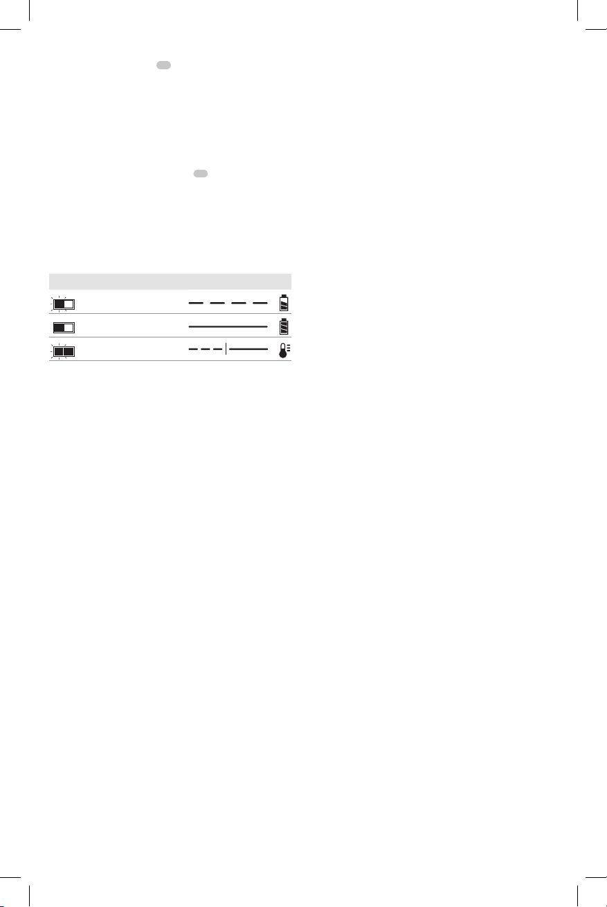
Charger Operation
Refer to the indicators below for the charge status of the
batterypack.
DCB107, DCB112, DCB113, DCB115, DCB118, DCB132
Charging
Fully Charged
Hot/Cold Pack Delay*
* DCB107, DCB112, DCB113, DCB115, DCB118, DCB132:
The red light will continue to blink, but a yellow indicator
light will be illuminated during this operation. Once the
battery pack has reached an appropriate temperature, the
yellow light will turn off and the charger will resume the
chargingprocedure.
The compatible charger(s) will not charge a faulty battery
pack. The charger will indicate faulty battery pack by
refusing to light or by displaying a problem pack or charger
blinkpattern.
NOTE: This could also mean a problem with acharger.
If the charger indicates a problem, take the charger and
battery pack to be tested at an authorized servicecenter.
Hot/Cold Pack Delay
When the charger detects a battery pack that is too hot
or too cold, it automatically starts a Hot/Cold Pack Delay,
suspending charging until the battery pack has reached an
appropriate temperature. The charger then automatically
switches to the pack charging mode. This feature ensures
maximum battery packlife.
A cold battery pack will charge at a slower rate than a warm
battery pack. The battery pack will charge at that slower rate
throughout the entire charging cycle and will not return to
maximum charge rate even if the battery packwarms.
The DCB118 charger is equipped with an internal fan
designed to cool the battery pack. The fan will turn on
automatically when the battery pack needs to becooled.
Never operate the charger if the fan does not operate
properly or if ventilation slots are blocked. Do not permit
foreign objects to enter the interior of thecharger.
Electronic Protection System
Li-Ion tools are designed with an Electronic Protection
System that will protect the battery pack against
overloading, overheating or deepdischarge.
The tool will automatically turn off if the Electronic
Protection System engages. If this occurs, place the lithiumion battery pack on the charger until it is fullycharged.
Wall Mounting
DCB107, DCB112, DCB113, DCB115, DCB118, DCB132
These chargers are designed to be wall mountable or to
sit upright on a table or work surface. If wall mounting,
locate the charger within reach of an electrical outlet,
and away from a corner or other obstructions which may
impede air flow. Use the back of the charger as a template
for the location of the mounting screws on the wall. Mount
the charger securely using drywall screws (purchased
separately) at least 1" (25.4 mm) long, with a screw head
diameter of 0.28–0.35" (7–9mm), screwed into wood to an
optimal depth leaving approximately 7/32" (5.5 mm) of the
screw exposed. Align the slots on the back of the charger
with the exposed screws and fully engage them in theslots.
Charger Cleaning Instructions
WARNING: Shock hazard. Disconnect
the charger from the AC outlet before cleaning. Dirt
and grease may be removed from the exterior of the
charger using a cloth or soft non-metallic brush. Do
not use water or any cleaningsolutions.
Important Charging Notes
1. Longest life and best performance can be obtained if
the battery pack is charged when the air temperature is
between 65°F and 75°F (18° – 24°C). DO NOT charge
the battery pack in an air temperature below +40°F
(+4.5°C), or above +104°F (+40°C). This is important
and will prevent serious damage to the batterypack.
2. The charger and battery pack may become warm to the
touch while charging. This is a normal condition, and
does not indicate a problem. To facilitate the cooling of
the battery pack after use, avoid placing the charger or
battery pack in a warm environment such as in a metal
shed or an uninsulatedtrailer.
3. If the battery pack does not charge properly:
a. Check operation of receptacle by plugging in a lamp
or other appliance;
b. Check to see if receptacle is connected to a light
switch which turns power off when you turn out
the lights;
c. Move the charger and battery pack to a location
where the surrounding air temperature is
approximately 65°F – 75°F (18° – 24°C);
d. If charging problems persist, take the tool, battery
pack and charger to your local servicecenter.
4. The battery pack should be recharged when it fails to
produce sufficient power on jobs which were easily
done previously. DO NOT CONTINUE to use under these
conditions. Follow the charging procedure. You may
also charge a partially used pack whenever you desire
with no adverse effect on the batterypack.
6
Page 9
5. Foreign materials of a conductive nature such as, but
not limited to, grinding dust, metal chips, steel wool,
aluminum foil, or any buildup of metallic particles
should be kept away from charger cavities. Always
unplug the charger from the power supply when there
is no battery pack in the cavity. Unplug the charger
before attempting toclean.
6. Do not freeze or immerse the charger in water or any
otherliquid.
Storage Recommendations
1. The best storage place is one that is cool and dry, away
from direct sunlight and excess heat orcold.
2. For long storage, it is recommended to store a fully
charged battery pack in a cool dry place out of the
charger for optimalresults.
NOTE: Battery packs should not be stored completely
depleted of charge. The battery pack will need to be
recharged beforeuse.
SAVE THESE INSTRUCTIONS FOR
FUTURE USE
ENGLISH
Fig. E
17
18
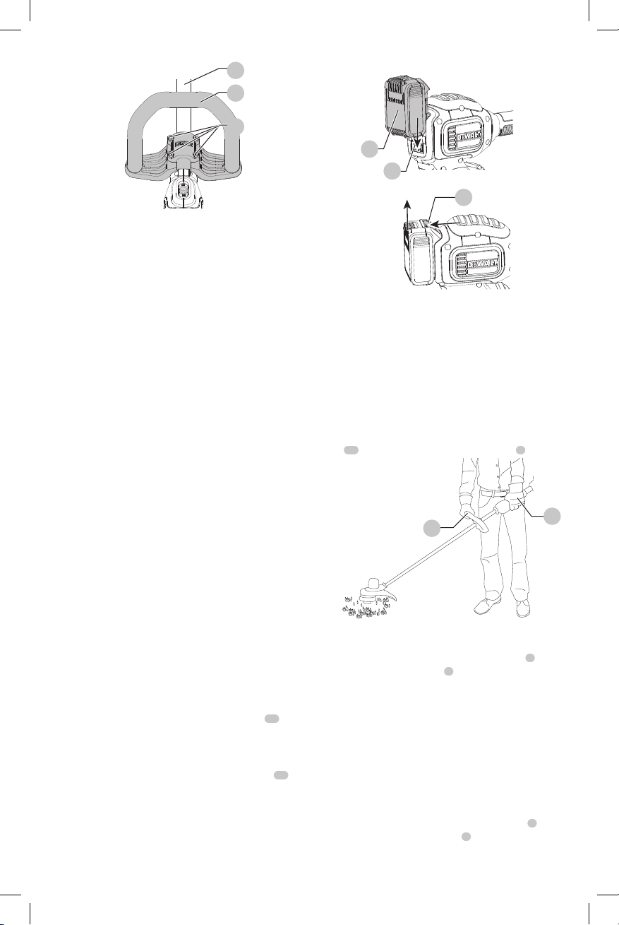
Attaching the Auxiliary Handle (Fig. A, F)
1. Slide the auxiliary handle
handle base
2. Hold the auxiliary handle in place and thread the
handle bolt
handlebase.
3. Tighten the handle bolt with the supplied hex wrench
18
4. Repeat for the other side of the auxiliaryhandle.
19
20
. Ensure the handle is securelyattached.
Fig. F
4
.
into the handle from the bottom of the
into the top hole of the
COMPONENTS (FIG. A)
WARNING: Never modify the power
tool or any part of it. Damage or personal injury
couldresult.
Refer to Figure A at the beginning of this manual for a
complete list ofcomponents.
Intended Use
This string trimmers is designed for professional trimming
applications. This product is not an edger and is not
intended to be used foredging.
DO NOT use under wet conditions or in presence of
flammable liquids orgases.
This string trimmer is a professional appliance. DO NOT
let children come into contact with the tool. Supervision is
required when inexperienced operators use thistool.
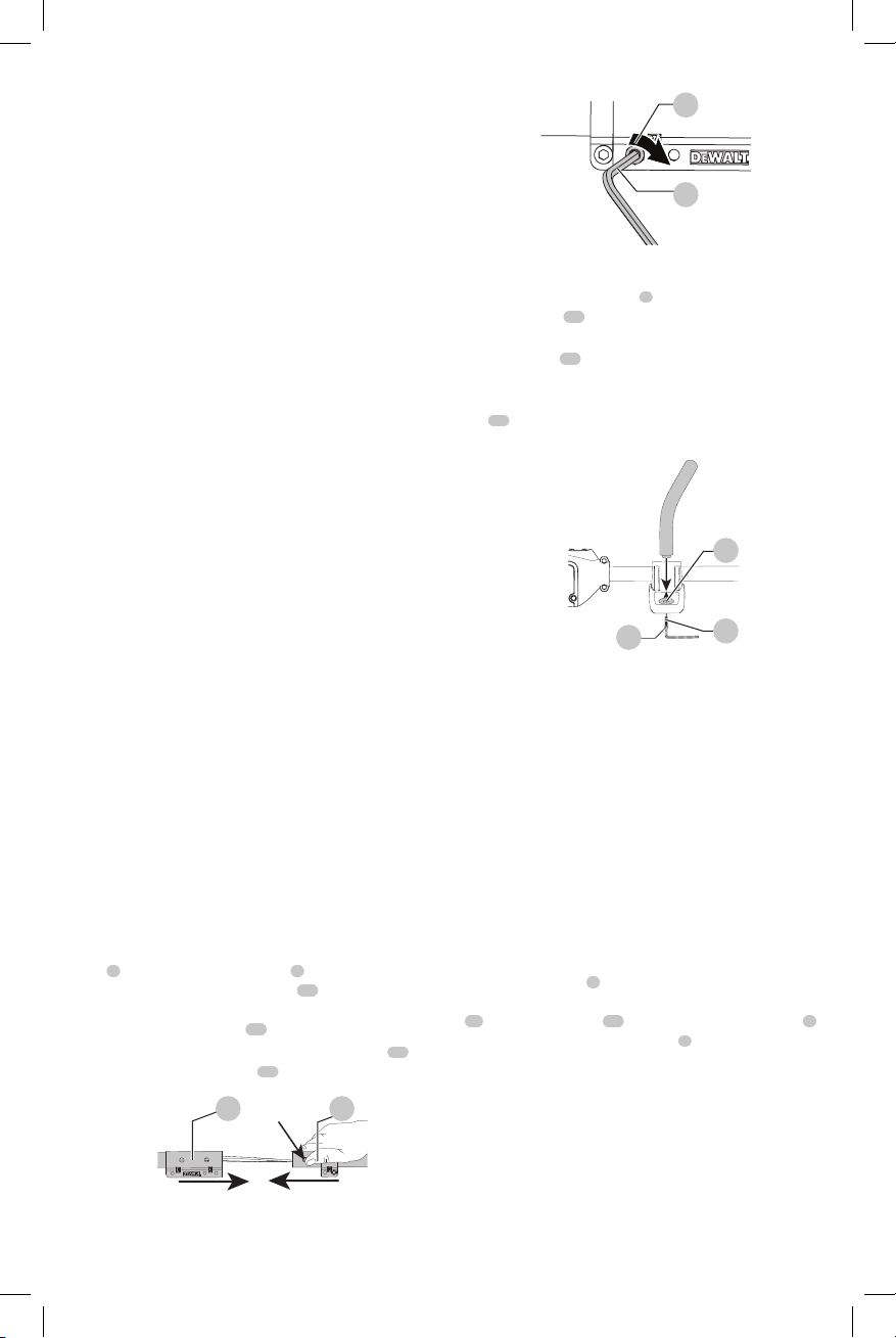
ASSEMBLY (FIG. A, D, E)
Assembling the Pole
1. To assemble the pole, line up the upper trimmer pole
6
and the lower trimmer pole
Press down the latching button
pole into the lower pole. Ensure the latching button
engages the latch hole
2. Secure the poles by tightening the middle bolt
the supplied hex wrench
Fig. D
15 16
7
as shown in Figure A.
15
and slide the upper
16
.
18
as shown in FigureE.
17
with
19
18
20
Adjustment (Fig. G)
WARNING: To reduce the risk
of serious personal injury, turn appliance
off and remove battery before making any
adjustments or removing/installing attachments
oraccessories.
WARNING: Never remove the guard.
Damage or personal injury couldresult.
WARNING: NEVER OPERATE
APPLIANCE WITHOUT GUARD FIRMLY IN PLACE.
The guard must always be properly attached on the
appliance to protect theuser.
The auxiliary handle
However, if adjustment is necessary, loosen the four bolts
21
with a hex wrench
up or down the upper trimmer pole
4
is positioned to maximize balance.
18
and slide the auxiliary handle
6
.
4
7
Page 10
ENGLISH
Fig.G
OPERATION
WARNING:To reduce the risk
of serious personal injury, turn appliance
off and remove battery before making any
adjustments or removing/installing attachments
oraccessories.
6
4
21
Fig. H
12
Fig. I
11
13
Proper Hand Position (Fig. J)
WARNING: Always use proper eye
protection that conforms to ANSI Z87.1 (CAN/CSA
Z94.3) while operating thisappliance.
WARNING:Remove the battery before
making any assembly, adjustments, or changing
accessories. Such preventive safety measures reduce
the risk of starting the TRIMMERaccidentally.
CAUTION: Before you begin trimming, only
use the appropriate type of cuttingline.
CAUTION: Inspect area to be trimmed and
remove any wire, cord, or string-like objects which
could become entangled in the rotating line or spool.
Be particularly careful to avoid any wire which might
be bent outwardly into the path of the appliance, such
as barbs at the base of a chain linkfence.
Installing and Removing the Battery Pack
(Fig. H, I)
WARNING: Make certain the lock-off
lever is not engaged to prevent switch actuation
before removing or installingbattery.
NOTE: For best results, make sure your battery pack is
fullycharged.
To install the battery pack: Align the battery pack
with the rails inside the battery housing and slide it into the
housing until the battery pack is firmly seated and ensure
that it does notdisengage.
To remove battery pack: Depress the release button
and firmly pull the battery pack out of the battery housing.
Insert it into the charger as described in the charger section
of thismanual.
8
12
13
WARNING: To reduce the risk of serious
personal injury, ALWAYS use proper hand position
as shown.
WARNING: To reduce the risk of serious
personal injury, ALWAYS hold securely in anticipation
of a suddenreaction.
Proper hand position requires one hand on the primary
14
handle
and one hand on the auxiliary handle
Fig. J
4
Switching Trimmer On and Off (Fig. A)
To turn the appliance on, squeeze the lock-off lever
then the variable speed trigger
off, release the variable speed trigger and the lock-offlever.
WARNING: Never attempt to lock the
trigger in the onposition.
1
. To turn the appliance
Speed Control Switch (Fig. A)
This string trimmer gives you the choice to operate
at a more efficient speed to extend the runtime for
larger jobs, or accelerate the trimmer speed for highperformancecutting.
To extend runtime, push the speed control switch
forward toward the auxillary handle
position. This mode is best for larger projects that require
more time tocomplete.
4
into the "LO"
4
.
14
2
and
3
Page 11
To accelerate the trimmer, pull the speed control switch
DeWALT
DeWALT
DeWALT
DeWALT
DeWALT
back toward the battery housing
This mode is best to cut through heavier growth and for
applications that need higherRPM.
NOTE: When in "HI" mode, runtime will be decreased as
compared to when trimmer is in "LO"mode.
11
into the "HI" position.
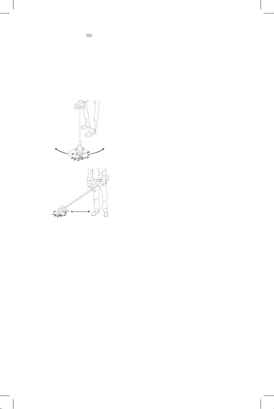
Trimming (Fig. K, L)
With the trimmer on, angle it and swing side to side as
shown in FigureK.
Maintain a minimum distance of 24 inches (610 mm)
between the guard and your feet as shown in FigureL.
Fig. K
Fig. L
Minimum
24 Inches (610 mm)
WARNING: Keep the rotating string
roughly parallel with the ground (tilted no more than
30 degrees). This trimmer is not an edger. DO NOT
TILT the trimmer so that the string is spinning near
a right angle to the ground. Flying debris can cause
seriousinjury.
Bump Feed Trimmer Line Feed
Your trimmer uses 0.080 inches (2.032 mm) diameter nylon
line. Cutting line will wear faster and require more feeding
if the cutting is done along sidewalks or other abrasive
surfaces or heavier weeds are beingcut.
As you use the trimmer, the string will get shorter due
to wear. Gently bump the trimmer on the ground while
running at normal speed and the line willfeed.
NOTE: Extending nylon line beyond the 13inch (330mm)
swath will negatively affect performance, runtime, and the
life of the trimmer due to potential of damaging motor.
Doing so may void thewarranty.
Helpful Cutting Tips
• Use the tip of the string to do the cutting; do not force
string head into uncutgrass.
ENGLISH
• Wire and picket fences cause extra string wear, even
breakage. Stone and brick walls, curbs, and wood may
wear stringrapidly.
• Do not allow spool cap to drag on ground or
othersurfaces.
• In long growth, cut from the top down and do not
exceed 12 inches (304.8 mm)high.
• Keep trimmer tilted toward the area being cut; this is
the best cuttingarea.
• The trimmer cuts when passing the unit from the left to
right. This will avoid throwing debris at theoperator.
• Avoid trees and shrubs. Tree bark, wood moldings,
siding, and fence posts can easily be damaged by
thestring.
Replacement Accessories
WARNING: To reduce the risk
of serious personal injury, turn appliance
off and remove battery before making any
adjustments or removing/installing attachments
oraccessories.
WARNING: The use of any accessory not
recommended by
could behazardous.
WARNING: Do not use any blades,
or any accessory or attachment other than those
recommended by
injury or product damage mayresult.
Use
orDWO1DT802.
When replacing the line, use only .080 inches (2.032 mm)
diameter line (Model No. DWO1DT801 or DWO1DT802 are
is recommended). Other sizes may degrade performance or
cause damage to thetrimmer.
replacement line Model No. DWO1DT801
for use with this appliance
on this trimmer. Serious
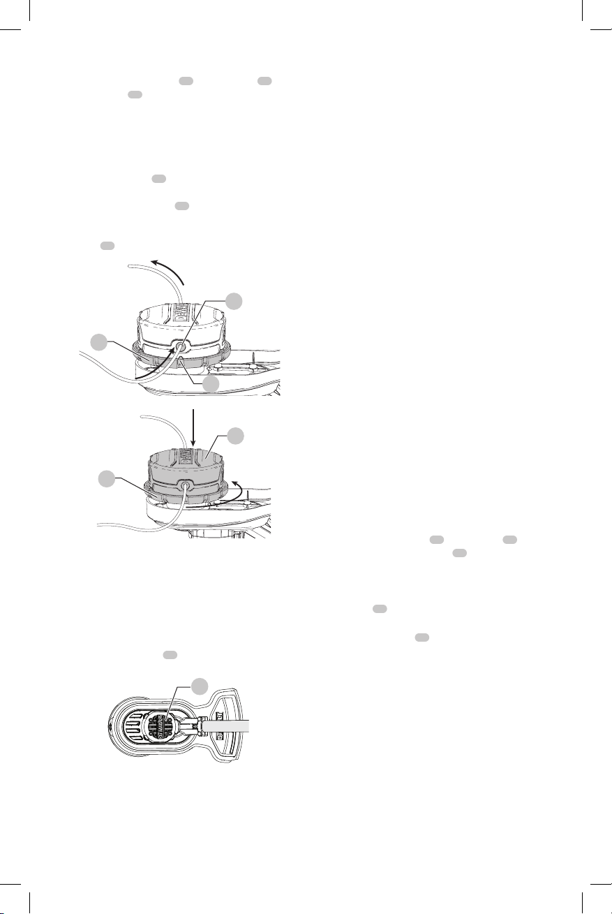
Reloading the Cutting Line (Fig. A, M, N)
WARNING: To reduce the risk of
serious personal injury, turn unit off and remove
the battery pack. An accidental start-up can
causeinjury.
CAUTION: Use only
spools and line. Using any other manufacturer's line
can reduce performance, damage the trimmer or
cause personalinjury.
Your trimmer uses 0.080 inches (2.032 mm) diameter
line. Do not use other size lines. This can degrade
performance, cause damage to the unit or injury
CAUTION: To avoid appliance damage, if
the cutting line protrudes beyond the trimming blade,
cut it off so that it just reaches theblade.
Use only
1. Removebattery.
replacementline.
replacement
9
Page 12
ENGLISH
DeWALT
DeWALT
DeWALT
DeWALT
2. Cut a max of 25 feet (8 m) length of trimmerline.
3. Align spool housing eyelets
the spool head
4. Thread one end of the trimmer line through an eyelet.
Guide the line through to the second eyelet and
continue to pull the line through until there are equal
lengths of string on each side of the spool housing as
shown in FigureM.
5. Secure the spool cap
Using your other hand, wind the string onto the spool
by rotating the spool head
shown in Figure N. Continue winding until 5 inches
(127mm) of string remain on each side of the spool
housing
Fig. M
10
24
.
22
as shown in FigureM.
with the arrow
25
from moving with one hand.
24
counter clockwise as
23
22
on
4. The line cutter on the edge of the guard can dull over
time. It is recommended you periodically touch-up the
sharpness of the blade with afile.
Cleaning
WARNING: Blow dirt and dust out of all
air vents with clean, dry air at least once a week. To
minimize the risk of eye injury, always wear ANSI Z87.1
approved eye protection when performingthis.
WARNING: Never use solvents or other
harsh chemicals for cleaning the non-metallic parts
of the appliance. These chemicals may weaken the
plastic materials used in these parts. Use a cloth
dampened only with water and mild soap. Never let
any liquid get inside the appliance; never immerse any
part of the appliance into aliquid.
Accessories
24
23
Fig.N
24
MAINTENANCE
WARNING: To reduce the risk
of serious personal injury, turn appliance
off and remove battery before making any
adjustments or removing/installing attachments
oraccessories.
1. Keep the air intake slots
(Fig.O).
Fig. O
26
clean to avoid overheating
26
WARNING: Since accessories, other than
those offered by
this product, use of such accessories with this tool
could be hazardous. To reduce the risk of injury, only
25
Recommended accessories for use with your tool are
available at extra cost from your local dealer or authorized
service center. If you need assistance in locating any
accessory, please contact
(1-800-433-9258).
recommended accessories should be used
with thisproduct.
have not been tested with
, call 1-800-4-
Replacement Accessories
Replacing Spool Assembly (Fig.A, P, Q)
25
10
.
until the hole
28
1. Rotate the spool housing
spindle plate aligns with notch
a screwdriver through the notch and into the hole, to
prevent the spindle fromturning.
2. Unscrew and remove the spool housing by turning the
spool head
3. NOTE: Do not try to remove the spool housing by
turning the spool cap
24
clockwise.
27
in the guard. Insert
in the
2. Your trimmer line can dry out over time. To keep
your line in top condition, store spare line in a plastic,
sealable bag with a tablespoon ofwater.
3. Plastic parts may be cleaned by using a mild soap and
a damprag.
10
Page 13
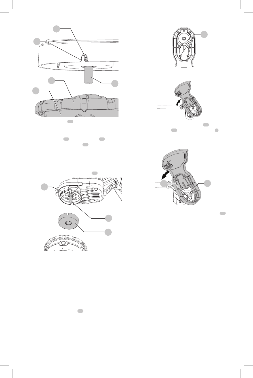
Fig. P
DeWALT
DeWALT
DeWALT
ENGLISH
27
28
Fig. R
32
24
25
4. Remove spindle plate
housing. Remove any dirt and grass from the motor
housing and spindleplate.
5. Install spindle plate
double D shaped retaining nut
inside the base of the spindleplate.
6. Align the spindle plate hole and notch, insert a
screwdriver back into the hole and thread the new
spool housing counterclockwise. Securely tighten the
new spool housing onto the spindle
Fig. Q
31
30
before installing a new
30
onto the spindle
31
on the spindle sits
29
29
.
, so the
29
30
3. Lift the guard off at an angle as shown in FigureS.
29
4. To attached a new guard, slide the tab
5. Replace and securely tighten the 4 guard screws
6. Replace the spool housing as described in the
Fig. S
33
guard under the lip
lower the back of the guard into place as shown in
FigureT.
Fig. T
Replacing Spool Housingsection.
34
of the motor housing
33
of the new
5
34
, then
32
.
Repairs
The charger and battery pack are notserviceable.
Replacing Guard (Fig. R, S, T)
An extended coverage guard is available (sold separately)
for extra coverage if desired. Use
guard Part NumberN496261.
WARNING: Never operate appliance
without guard firmly inplace.
1. Remove the spool housing as described in the
Replacing Spool Housingsection.
2. Remove the 4 guard screws
replacement
32
shown in FigureR.
WARNING: To assure product
SAFETY and RELIABILITY, repairs, maintenance
and adjustment (including brush inspection and
replacement, when applicable) should be performed
by a
authorized service center. Always use identical
replacementparts.
factory service center or a
Register Online
Thank you for your purchase. Register your product nowfor:
• WARRANTY SERVICE: Registering your product will
help you obtain more efficient warranty service in case
there is a problem with yourproduct.
• CONFIRMATION OF OWNERSHIP: In case of
an insurance loss, such as fire, flood or theft, your
registration of ownership will serve as your proof
ofpurchase.
11
Page 14

ENGLISH
DeWALT
DeWALT
DeWALT
DeWALT
DeWALT
DeWALT
DeWALT
• FOR YOUR SAFETY: Registering your product will
allow us to contact you in the unlikely event a safety
notification is required under the Federal Consumer
SafetyAct.
Register online at www.dewalt.com/register.
Three Year Limited Warranty
will repair, without charge, any defects due to
faulty materials or workmanship for three years from
the date of purchase. This warranty does not cover part
failure due to normal wear or tool abuse. For further detail
of warranty coverage and warranty repair information,
visit www.dewalt.com or call 1-800-4433-9258). This warranty does not apply to accessories
or damage caused where repairs have been made
or attempted by others. THIS LIMITED WARRANTY IS
GIVEN IN LIEU OF ALL OTHERS, INCLUDING THE IMPLIED
WARRANTY OF MERCHANTABILITY AND FITNESS FOR A
PARTICULAR PURPOSE, AND EXCLUDES ALL INCIDENTAL
OR CONSEQUENTIAL DAMAGES. Some states do not allow
limitations on how long an implied warranty lasts or the
exclusion or limitation of incidental or consequential
damages, so these limitations may not apply to you. This
warranty gives you specific legal rights and you may have
other rights which vary in certain states orprovinces.
In addition to the warranty,
byour:
will maintain the tool and replace worn parts
caused by normal use, for free, any time during the first year
afterpurchase.
2 YEARS FREE SERVICE ON DEWALT BATTERY PACKS
DC9071, DC9091, DC9096, DC9182, DC9280, DC9360, DCB120,
DCB127, DCB201, DCB203, DCB203BT, DCB207, DCB361
3 YEARS FREE SERVICE ON DEWALT BATTERY PACKS
DCB200, DCB204, DCB204BT, DCB205, DCB205BT, DCB206,
NOTE: Battery warranty voided if the battery pack is
tampered with in any way.
for any injury caused by tampering and may prosecute
warranty fraud to the fullest extent permitted bylaw.
If you are not completely satisfied with the performance of
your
can return it within 90 days from the date of purchase with
a receipt for a full refund – no questionsasked.
LATIN AMERICA: This warranty does not apply to products
sold in Latin America. For products sold in Latin America,
see country specific warranty information contained in
the packaging, call the local company or see website for
warrantyinformation.
FREE WARNING LABEL REPLACEMENT: If your warning
labels become illegible or are missing, call 1-800-4(1-800-433-9258) for a freereplacement.
1 YEAR FREE SERVICE
90 DAY MONEY BACK GUARANTEE
Power Tool, Laser, or Nailer for any reason, you
tools are covered
DCB606, DCB609
is not responsible
(1-800-
12
Page 15

Définitions : symboles et termes d'alarmes sécurité
DeWALT
DeWALT
Ces guides d'utilisation utilisent les symboles et termes d'alarmes sécurité suivants pour vous prévenir de situations
dangereuses et de risques de dommages corporels ou matériels.
DANGER : indique une situation dangereuse imminente qui, si elle n’est pas évitée, entraînera la mort ou
des blessuresgraves.
AVERTISSEMENT : indique une situation potentiellement dangereuse qui, si elle n’est pas évitée,
pourrait entraîner la mort ou des blessuresgraves.
ATTENTION : indique une situation potentiellement dangereuse qui, si elle n’est pas évitée, pourrait
entraîner des blessures légères oumodérées.
(Si utilisé sans aucun terme) Indique un message propre à la sécurité.
AVIS : indique une pratique ne posant aucun risque de dommages corporels mais qui par contre, si rien n’est
fait pour l’éviter, pourrait poser des risques de dommages matériels.
FRANÇAIS
Fig. A
10
1
Détente à vitesse
variable
2
Levier de blocage
3
Interrupteur de réglage
de vitesse
4
Poignée auxiliaire
5
Carter du moteur
6
Partie supérieure de la
perche du taille-bordure
7
Partie inférieure de la
perche du taille-bordure
12
13
2
3
4
8
6
5
7
9
AVERTISSEMENT! lire tous
8
Dispositif de fixation de
la perche
9
Pare-main
10
Boîtier de la bobine
11
Compartiment des piles
12
Bloc-piles
13
Bouton de dégagement
du bloc-piles
14
Poignée
les avertissements de sécurité et toutes les
directives. Le non-respect des avertissements et des
directives pourrait se solder par un choc électrique, un
incendie et/ou une blessuregrave.
AVERTISSEMENT : afin de
réduire le risque de blessures, lire le mode d’emploi
del’outil.
Pour toute question ou remarque au sujet de cet outil
ou de tout autre outil
sans frais : 1-800-4-
1
(1-800-433-9258).
11
14
, composez le numéro
13
Page 16

FRANÇAIS
DeWALT
Avertissements importants concernant
la sécurité
AVERTISSEMENT : afin de
réduire le risque de blessure :
• Avant toute utilisation, assurez-vous que toutes
les personnes qui utiliseront l’outil lisent et
comprennent toutes les consignes de sécurité
et les autres renseignements compris dans le
présentmanuel.
• Conservez ces instructions et consultezlessouvent.
AVERTISSEMENT : lors de
l’utilisation d’outils de jardinage électriques, les
mesures de précaution de base devraient toujours
être prises pour réduire la possibilité d’incendie,
de choc électrique et de blessures, en suivant les
recommandationssuivantes.
LISEZ TOUTES LES INSTRUCTIONS
1 . Évitez les environnements dangereux : NE PAS utiliser
des outils dans des endroits humides ou mouillés. NE PAS
utiliser les outils électriques portatifs dans une atmosphère
gazeuse ou explosive. Les moteurs de ces outils produisent
des étincelles et ces étincelles pourraient enflammer
lesvapeurs.
2 . Ne pas utiliser sous lapluie.
3 . Gardez tous les passants éloignés : à une distance
sécuritaire de l’aire de travail, particulièrement lesenfants.
4 . Portez des vêtements appropriés : ne pas porter des
vêtements amples ou des bijoux. Il peuvent se coincer dans
les pièces qui se déplacent. Les gants et les chaussures
à semelles en caoutchouc solides sont recommandés
lorsque vous travaillez à l’extérieur. Portez une protection
pour vos cheveux afin de lesretenir.
5 . Portez toujours une protection des yeux : portez une
protection des yeux approuvé ANSI Z87.1 en tout temps
lorsque la pile est installée. De plus, utilisez un masque
facial ou antipoussières. Des lunettes de sécurité sont
disponibles à un coût supplémentaire dans votre centre
de services
servicesautorisé.
6 . Utilisez le bon outil : ne pas utiliser cet outil pour toute
tâche autre que celles pour lesquelles il estconçu.
7 . Évitez les démarrages accidentels : ne pas transporter
avec votre doigt sur la gâchette si la pile estinstallée.
8 . Ne pas forcer l’outil : le travail sera mieux fait et avec
moins de probabilité de risque à la vitesse pour laquelle il
a étéconçu.
9 . Ne pas s’étirer : maintenez vos pieds bien d’aplomb sur le
sol et un bon équilibre en touttemps.
10 . Demeurez vigilant : regardez ce que vous faites. Faites
preuve de bon sens. NE PAS utiliser sous l’influence de
l’alcool ou de drogues, ou si vous êtes fatigué ou malade.
local ou dans un établissement de
11 . Débranchez l’outil : retirez la pile lorsque vous n’utilisez
pas l’outil, avant de réparer, lorsque vous changez les
accessoires comme les lames etautres.
12 . Entreposez les outils arrêtés à l’intérieur : lorsqu’ils
ne sont pas utilisés, les outils doivent être entreposés à
l’intérieur dans un endroit sec et élevé ou verrouillé hors de
portée desenfants.
13 . Entretenez soigneusement l’outil : gardez bords
coupants aiguisés et nettoyez pour une meilleure
performance et afin de réduire le risque de blessure. Pour
lubrifier l’outil et remplacer les accessoires, suivez les
directives du manuel. Inspectez régulièrement le cordon
de l’outil et s’il est endommagé, faites-le réparer dans un
établissement de services autorisé. Inspectez régulièrement
les rallonges et remplacez-les si elles sont endommagées.
Gardez vos mains sèches, propres et exemptes de graisse
et depoussière.
14 . Vérifiez les pièces endommagées : avant toute
utilisation ultérieure de l’outil, un protecteur ou une autre
pièce qui est endommagé doit être soigneusement vérifié
afin de déterminer s’il fonctionnera correctement et s’il
effectuera la fonction prévue. Vérifiez l’alignement des
pièces qui se déplacent, les fixations des pièces qui se
déplacent, le bris des pièces, le montage et tout autre état
qui peut affecter son utilisation. Un protecteur ou une
autre pièce qui est endommagé doit être convenablement
réparé ou remplacé par un centre de services autorisé sauf
si c’est indiqué ailleurs dans cemanuel.
15 . Dommages à l’outil : si vous frappez ou si vous vous
emmêlé avec un objet étranger, arrêtez immédiatement
l’outil, retirez la pile, vérifiez les dommages et faites réparer
les dommages avant de tenter de leréutiliser.
16 . Protecteur : ne pas utiliser cet outil sans avoir fixé le
protecteur. Maintenez les protecteurs en place en bon état
defonctionnement.
17 . NE PAS immerger l’outil dans l’eau ou l’asperger avec un
tuyau. NE PAS laisser pénétrer tout liquide à l’intérieur.
Si l’outil est mouillé, laissez-le sécher pendant au moins
48heures.
18 . NE PAS entreposer l’outil sur ou près de fertilisants ou de
produitschimiques.
19 . NE PAS nettoyer avec une laveuse àpression.
20 . NE PAS charger l’outil sous la pluie ou dans des
endroitsmouillés.
Avertissements spécifiques pour les taillebordures
AVERTISSEMENT : ce produit
n’est pas une déligneuse et n’est pas conçu pour être
utilisé à des fins dedélignage.
• Ne pas utiliser cet outil lorsque vous êtes pieds nus ou que
vous portez des sandalesouvertes.
• Portez des pantalons longs pour protéger vosjambes.
• ASSUREZ-VOUS que les autres personnes et les
animaux sont à une distance d’au moins 30 m
(100pieds).
14
Page 17

• Gardez votre visage, vos mains et vos pieds hors de portez
DeWALT
DeWALT
DeWALT
du fil en rotation en touttemps.
• Le fil en rotation a pour fonction de couper. Soyez
prudent lorsque vous taillez des moustiquaires et des
plantesdésirables.
• Afin de réduire le risque de blessures par rebond (ricochet),
travaillez à distance de tout objet solide à proximité
comme un mur, des marches, une grosse pierre, un arbre,
etc. Faites très attention lorsque vous travaillez près
d’objets solides et au besoin, faites une coupe à lamain.
Avertissements de sécurité
supplémentaires
ATTENTION : utilisez seulement des
bobines et du fil de remplacement
fil de tout autre fabricant peut réduire la performance,
endommager le taille-bordure ou causer une
blessurecorporelle.
Votre taille-bordure utilise un fil ayant un diamètre de
2,032 mm (0,080 po.). N’utilisez pas d’autres lignes de
taille. Cela peut dégrader les performances, causer des
dommages à l’appareil ou desblessures.
AVERTISSEMENT : si la
gâchette ne met pas l’outil en marche ou si ne l’éteint
pas, ne pas se servir de l’outil. Tout outil qui ne peut
être contrôlé avec la gâchette est dangereux et doit
êtreréparé.
AVERTISSEMENT : certaines
poussières créées par ce produit contiennent des
produits chimiques reconnus dans l’État de la
Californie pour causer le cancer, des anomalies
congénitales ou autres effets nuisibles sur la
reproduction. Certains exemples de ces produits
chimiques sont:
• des composants de fertilisants;
• des composants d’insecticides, d’herbicides et de
pesticides;
• de l’arsenic et du chrome provenant du bois de
construction traitéchimiquement.
Pour réduire votre exposition à ces produits chimiques,
porter un équipement de sécurité approuvé comme un
masque anti-poussières conçu spécialement pour filtrer les
particulesmicroscopiques.
L’étiquette apposée sur votre outil peut inclure les symboles
suivants. Les symboles et leur définition sont indiqués ci-après:
V ......................... volts
Hz ....................... hertz
min ..................... minutes
or DC ...... courant continu
...................... fabrication classe I
…/min .............. par minute
BPM .................... battements par
(mis à la terre)
minute
IPM ..................... impacts par minute
RPM .................... revolutions per
sfpm ................... pieds linéaires par
SPM (FPM) ......... fréquence par
A ......................... ampères
W ........................ watts
. Utiliser un
minute
minute (plpm)
minute
FRANÇAIS
or AC ........... courant alternatif
or AC/DC .... courant alternatif
ou continu
...................... fabrication classe II
(double isolation)
no ....................... vitesse à vide
n ......................... vitesse nominale
...................... borne de terre
...................... symbole
d’avertissement
..................... radiation visible
..................... protection
respiratoire
..................... protection oculaire
..................... protection auditive
..................... lire toute la
documentation
BLOCS-PILES ET CHARGEURS
Le bloc-piles n’est pas totalement chargé d’usine. Avant
d’utiliser le bloc-piles et le chargeur, lire les consignes de
sécurité ci-après puis suivre la procédure de chargement
indiquée. Pour commander un bloc-piles de rechange,
s’assurer d’en inclure le numéro de catalogue et latension.
Cet outil fonctionne avec un chargeur
de bien lire toutes les consignes de sécurité avant toute
utilisation du chargeur. Consulter le tableau en fin de
manuel pour connaître les compatibilités entre chargeurs
et blocs-piles.
LIRE TOUTES LES CONSIGNES
. S’assurer
Consignes importantes de sécurité
les blocs-piles
AVERTISSEMENT : lire toutes
les instructions et toutes les consignes de
sécurité propres au bloc-piles, au chargeur
et à l’outil électrique. Tout manquement aux
avertissements et instructions pose des risques
de décharges électriques, d’incendie et/ou de
blessures graves.
• Ne pas recharger ou utiliser un bloc-piles en milieu
déflagrant, en présence, par exemple, de poussières,
gaz ou liquides inflammables. Le fait d’insérer ou
retirer un bloc-piles de son chargeur pourrait causer
l’inflammation de poussières ou d’émanations.
• NE JAMAIS forcer l’insertion d’un bloc-piles dans un
chargeur. NE modifier un bloc-piles d’AUCUNE façon
pour le faire rentrer dans un chargeur incompatible,
car il pourrait se briser et causer des dommages
corporels graves. Consulter le tableau en dernière page
de ce manuel pour connaître les compatibilités entre
chargeurs et blocs-piles.
• Recharger les blocs-piles exclusivement dans des
chargeurs
• NE PAS éclabousser le bloc-piles ou l’immerger dans l’eau
ou dans tout autreliquide.
• Ne pas entreposer ou utiliser l’appareil et le bloc-
piles en présence de températures ambiantes
pouvant excéder 40°C (104°F) (comme dans des
hangars ou des bâtiments métalliques l’été). Pour
préserver leur durée de vie, entreposer les blocs-piles dans
un endroit frais etsec.
REMARQUE: ne pas mettre un bloc-piles dans un
outil dont la gâchette est verrouillée en position de
.
15
Page 18

FRANÇAIS
DeWALT
DeWALT
marche. Ne jamais bloquer l’interrupteur en position
deMARCHE.
• Ne pas incinérer le bloc-piles même s’il est
sévèrement endommagé ou complètement usagé,
car il pourrait exploser et causer un incendie.
Pendant l’incinération des blocs-piles au lithium-ion, des
vapeurs et matières toxiques sontdégagées.
• En cas de contact du liquide de la pile avec la peau,
rincer immédiatement au savon doux et à l’eau. En
cas de contact oculaire, rincer l’œil ouvert à l’eau claire
une quinzaine de minutes ou jusqu’à ce que l’irritation
cesse. Si des soins médicaux s’avéraient nécessaires, noter
que l’électrolyte de la pile est composé d’un mélange de
carbonates organiques liquides et de sels delithium.
• Le contenu des cellules d’une pile ouverte peut
causer une irritation respiratoire. En cas d’inhalation,
exposer l’individu à l’air libre. Si les symptômes persistent,
consulter unmédecin.
AVERTISSEMENT : risques de
brûlure. Le liquide de la pile peut s’enflammer s’il est
exposé à des étincelles ou à uneflamme.
AVERTISSEMENT : risques
d’incendie. Ne jamais tenter d’ouvrir le bloc-piles
pour quelque raison que ce soit. Si le boîtier du
bloc-piles est fissuré ou endommagé, ne pas l’insérer
dans un chargeur. Ne pas écraser, laisser tomber, ou
endommager les blocs-piles. Ne pas utiliser un blocpiles ou un chargeur qui a reçu un choc violent, ou si
l’appareil est tombé, a été écrasé ou endommagé de
quelque façon que ce soit (p. ex. percé par un clou,
frappé d’un coup de marteau, piétiné). Les blocs-piles
endommagés doivent être renvoyés à un centre de
réparation pour y êtrerecyclés.
Transport
AVERTISSEMENT : risques
d’incendie. Au moment de ranger ou transporter
le bloc-piles, veiller à protéger ses bornes à
découvert de tout objet métallique. Par exemple,
éviter de placer le bloc-piles dans un tablier, une
poche, une boîte à outils ou un tiroir, etc. contenant
des objets tels que clous, vis, clés, etc. Le fait de
transporter des blocs-piles comporte des risques
d’incendie, car les bornes des piles pourraient
entrer, par inadvertance, en contact avec des
objets conducteurs, tels que: clés, pièces de
monnaie, outils ou autres. La réglementation sur les
produits dangereux (Hazardous Material Regulations)
du département américain des transports interdit, en
fait, le transport des blocs-piles dans les commerces ou
dans les avions dans les bagages de cabine, À MOINS
qu’ils ne soient correctement protégés de tout courtcircuit. Aussi lors du transport individuel de blocs-piles,
s’assurer que leurs bornes sont bien protégées et
isolées de tout matériau pouvant entrer en contact
avec elles et provoquer un court-circuit.
16
Expédition du bloc-piles
Le bloc-piles DeWALT FLEXVOLTMC possède deux modes:
Utilisation et Expédition.
Mode Utilisation: lorsque le bloc-piles FLEXVOLTMC est par
lui-même ou dans un produit DeWALT 20v max*, il
fonctionnera comme un bloc-piles de 20v max*. Lorsque le
bloc-piles FLEXVOLTMC est dans un produit de 60v max* ou
120v max* (deux blocs-piles de 60v max*), il fonctionnera
comme un bloc-piles de 60v max*.
Mode Expédition: lorsque
le capuchon est inséré sur
le bloc-piles FLEXVOLTMC,
le bloc-piles est en mode
Expédition. Les modules
de cellules sont électriquement déconnectés du bloc le
faisant correspondre à trois blocs-piles d’un wattheure (Wh)
inférieur comparé à un bloc-piles de wattheure élevé. Ce
passage à trois blocs-piles à un wattheure inférieur peut
permettre au bloc-piles d’être exempté de suivre certaines
directives d’expédition imposées sur les blocs-piles de
wattheuresupérieur.
L’étiquette du bloc-piles donne deux estimations de
wattheures (se reporter à l’exemple). Selon comment le
bloc-piles est expédié, l’estimation appropriée de wattheure
doit être utilisée pour déterminer les modalités d’expédition
lui correspondant. Si le capuchon d’expédition est utilisé,
le bloc-piles sera considéré comme 3 blocs-piles au
wattheure indiqué pour «Expédition». S’il est expédié sans
le capuchon ou dans un outil, le bloc-piles sera considéré
comme un seul bloc-piles au wattheure indiqué à côté de
«Utilisation».
Par exemple, le Wh de expédition pourra indiquer
3x40Wh, ce qui correspond à 3 blocs-piles de
40wattheures chacun. L’utilisation du Wh pourra indiquer
120Wh (sous-entendu 1bloc-piles).
Exemple d’étiquetage d’utilisation et d’expédition
USE: 120 Wh Shipping: 3 x 40 Wh
FLEXVOLT
MC
Témoin de Charge du Bloc-Piles (Fig.B)
Certains blocs-piles
charge qui consiste en trois voyants Del verts indiquant le
niveau de charge du bloc-piles.
Le témoin de charge indique approximativement le niveau
de charge restant dans le bloc-piles en fonction des voyants
suivants:
Pour activer le témoin de charge, maintenez appuyé le
bouton du témoin de charge. Une combinaison des trois
voyants Del verts s’allumera indiquant le niveau de charge.
Lorsque le niveau de charge du bloc-pile atteint la limite
possèdent un témoin de
Chargé de 75 à 100%
Chargé de 51 à 74%
Chargé de < 50%
Le bloc-piles doit être rechargé
Page 19

minimale d’utilisation, le témoin de charge reste éteint et le
DeWALT
DeWALT
DeWALT
DeWALT
DeWALT
bloc-piles doit êtrerechargé.
REMARQUE: le témoin de charge ne fait qu’indiquer
le niveau de charge du bloc-piles. Il ne donne aucune
indication quant au fonctionnement de l’outil. Son propre
fonctionnement pourra aussi varier en fonction des
composants produit, de la température et de l’application
d’utilisation.
Pour plus d’informations quant au témoin de charge du
bloc-piles, veuillez appeler le 1-800-4-
9258) ou vous rendre sur notre site www.dewalt.com.
Fig. B
Le sceau SRPRC®
Le sceau SRPRC® (Société de recyclage des
piles rechargeables du Canada) apposé
sur une pile au nickel-cadmium, à hydrure
métallique de nickel ou au lithium-ion
(ou un bloc-piles) indique que les coûts
de recyclage de ces derniers en fin d’utilisation ont déjà été
réglés par
ou aux ordures municipales des piles au nickel-cadmium, à
l’hydrure métallique de nickel ou au lithium-ion, est illégale;
le programme de l’Appel à Recycler® constitue donc une
solution pratique etécologique.
Appel à Recycler Canada, Inc., en collaboration avec
programme aux États-Unis et au Canada pour faciliter la
collecte des piles au nickel-cadmium, à l’hydrure métallique
de nickel ou au lithium-ion usagées. Aidez-nous à protéger
l’environnement et à conserver nos ressources naturelles
en renvoyant les piles au nickel-cadmium, à l’hydrure
métallique de nickel ou au lithium-ion usagées à un centre
de réparation autorisé
qu’elles y soient recyclées. On peut en outre se renseigner
auprès d’un centre de recyclage local pour connaître
d’autres sites lesacceptant.
SRPRC® est une marque déposée de l’Appel à Recycler
Canada,Inc.
. Dans certaines régions, la mise au rebut
et d’autres utilisateurs de piles, a mis sur pied de
ou chez votre détaillant afin
Directives de sécurité importantes
propres à tous les chargeurs de piles
AVERTISSEMENT : lire toutes
les instructions et toutes les consignes de
sécurité propres au bloc-piles, au chargeur
et à l’outil électrique. Tout manquement aux
avertissements et instructions pose des risques
de décharges électriques, d’incendie et/ou de
blessures graves.
• NE PAS tenter de charger de bloc-piles avec des
chargeurs autres que ceux décrits dans ce manuel.
Le chargeur et son bloc-piles ont été conçus tout
spécialement pour fonctionnerensemble.
(1-800-433-
FRANÇAIS
• Ces chargeurs n’ont pas été conçus pour une
utilisation autre que recharger les blocs-piles
rechargeables
comporte des risques d’incendie, de chocs électriques ou
d’électrocution.
• Protéger le chargeur de la pluie ou de laneige.
• Tirer sur la fiche plutôt que sur le cordon pour
débrancher le chargeur. Cela permet de réduire
les risques d’endommager la fiche ou le cordon
d’alimentation.
• S’assurer que le cordon est protégé de manière à
ce que personne ne marche ni ne trébuche dessus,
ou à ce qu’il ne soit ni endommagé ni soumis à
aucunetension.
• N’utiliser une rallonge qu’en cas de nécessité
absolue. L’utilisation d’une rallonge inadéquate
comporte des risques d’incendie, de chocs électriques ou
d’électrocution.
• Pour utiliser un chargeur à l’extérieur, le placer dans
un endroit sec et utiliser une rallonge conçue pour
l’extérieur. L’utilisation d’une rallonge conçue pour
l’extérieur réduit les risques de chocsélectriques.
• Pour la sécurité de l’utilisateur, utiliser une rallonge
de calibre adéquat (AWG, American Wire Gauge
[calibrage américain normalisé des fils électriques]).
Plus le calibre est petit, et plus sa capacité est grande. Un
calibre16, par exemple, a une capacité supérieure à un
calibre18. L’usage d’une rallonge de calibre insuffisant
causera une chute de tension qui entraînera perte de
puissance et surchauffe. Si plus d’une rallonge est utilisée
pour obtenir une certaine longueur, s’assurer que chaque
rallonge présente au moins le calibre de fil minimum. Le
tableau ci-dessous illustre les calibres à utiliser selon la
longueur de rallonge et l’intensité nominale indiquée sur
la plaque signalétique. En cas de doute, utiliser le calibre
suivant. Plus le calibre est petit, plus la rallonge peut
supporter decourant.
Calibre minimum pour les cordons d'alimentation
Volts
120 V 7,6 (25) 15,2 (50) 30,5 (100) 45,7 (150)
240 V 15,2 (50) 30,5 (100) 61,0 (200) 91,4 (300)
Ampères
Plus que Pas plus
10 12 16 16 14 12
12 16 14 12 Non recommandé
• Ne poser aucun objet sur le chargeur. Ne pas mettre
le chargeur sur une surface molle qui pourrait en
bloquer la ventilation et provoquer une surchauffe
interne. Éloigner le chargeur de toute source de chaleur.
Le chargeur dispose d’orifices d’aération sur le dessus et le
dessous duboîtier.
• Ne pas le faire fonctionner avec un cordon
d’alimentation ou une ficheendommagée.
• Ne pas utiliser le chargeur s’il a reçu un coup,
fait une chute ou a été endommagé de quelque
que
0 6 18 16 16 14
6 10 18 16 14 12
. Toute autre utilisation
Longueur totale du cordon
d'alimentation en mètre (pieds)
AWG
17
Page 20

FRANÇAIS
DeWALT
façon que ce soit. Le ramener dans un centre de
réparationagréé.
• Ne pas démonter le chargeur. Pour tout service
ou réparation, le rapporter dans un centre de
réparation agréé. Le fait de le réassembler de façon
incorrecte comporte des risques de chocs électriques,
d’électrocution et d’incendie.
• Débrancher le chargeur du secteur avant tout
entretien. Cela réduira tout risque de chocs
électriques. Le fait de retirer le bloc-piles ne réduira pas
cesrisques.
• NE JAMAIS tenter de connecter 2 chargeursensemble.
• Le chargeur a été conçu pour être alimenté en
courant électrique domestique standard de 120
volts. Ne pas tenter de l’utiliser avec toute autre
tension. Cela ne s’applique pas aux chargeurs de
postesmobiles.
AVERTISSEMENT : risques de
chocs électriques. Ne laisser aucun liquide pénétrer
dans le chargeur, des chocs électriques pourraient
enrésulter.
AVERTISSEMENT : risques de
brûlure. Ne submerger le bloc-piles dans aucun liquide
et le protéger de toute infiltration de liquide. Ne jamais
tenter d’ouvrir le bloc-piles pour quelque raison que
ce soit. Si le boîtier plastique du bloc-piles est brisé ou
fissuré, le retourner dans un centre de réparation pour
y êtrerecyclé.
ATTENTION : risques de brûlure.
Pour réduire tout risque de dommages corporels, ne
recharger que des blocs-piles rechargeables
Tout autre type de piles pourrait exploser et causer des
dommages corporels etmatériels.
AVIS : sous certaines conditions, lorsque le
chargeur est connecté au bloc d’alimentation, des
matériaux étrangers pourraient court-circuiter le
chargeur. Les corps étrangers conducteurs tels que
(mais pas limité à) poussières de rectification, débris
métalliques, laine d’acier, feuilles d’aluminium,
ou toute accumulation de particules métalliques
doivent être maintenus à distance des orifices du
chargeur. Débrancher systématiquement le chargeur
lorsque le bloc-piles n’y est pas inséré. Débrancher
systématiquement le chargeur avant toutentretien.
Chargement du bloc-piles (Fig. C)
1. Branchez le chargeur dans la prise appropriée avant d’y
insérer le bloc-piles.
18
Fig. C
12
13
2. Insérer le bloc-piles
assurant qu’il y est correctement calé. Le voyant rouge
(charge) clignotera de façon continue indiquant que le
cycle de chargement acommencé.
3. En fin de charge, le voyant rouge restera ALLUMÉ de
façon continue. Le bloc-piles est alors complètement
rechargé et peut être utilisé ou laissé dans le chargeur.
Pour retirer le bloc-piles du chargeur, appuyez sur le
bouton de libération du bloc-piles
REMARQUE: pour assurer des performances optimales
et une durée de vie maximale des blocs-piles au lithiumion, recharger pleinement le bloc-piles avant toute
utilisationinitiale.
Utilisation du chargeur
Reportez-vous aux indications du tableau ci-dessous pour
consulter le statut de charge du bloc-piles.
DCB107, DCB112, DCB113, DCB115, DCB118, DCB132
.
Bloc-piles en Cours
de Chargement
Bloc-piles Chargé
Suspension de Charge Contre
le Chaud/Froid*
* DCB107, DCB112, DCB113, DCB115, DCB118, DCB132:
le voyant rouge ne cessera de clignoter, mais un voyant
jaune restera allumé pendant cette opération. Lorsque
le bloc-piles aura repris une température appropriée,
le voyant jaune s’éteindra et le chargeur reprendra sa
procédure decharge.
Le chargeur ne pourront recharger des blocs-piles
défectueux. Le chargeur indiquera qu’un bloc-piles est
défectueux en refusant de s’allumer ou en affichant blocpiles ou chargeurdéfectueux.
REMARQUE: cela pourra aussi indiquer un problème avec
lechargeur.
Si le problème provient du chargeur, faites vérifier le
chargeur et le bloc-piles chez un centre de réparationagréé.
Fonction de suspension de charge contre le chaud/
froid
Lorsque le chargeur détecte un bloc-piles trop chaud
ou trop froid, il démarre automatiquement la fonction
13
dans le chargeur, en vous
12
sur le bloc-piles.
Page 21

de suspension de charge contre le chaud, suspendant
le chargement jusqu’à ce que le bloc-piles ait repris
une température appropriée. Le chargeur ensuite se
remettra automatiquement en mode de chargement.
Cette caractéristique assure aux blocs-piles une durée de
viemaximale.
Un bloc-piles froid se rechargera moins vite qu’un bloc-piles
chaud. Le bloc-piles se rechargera à ce rythme plus lent tout
au cours du cycle de charge et ne retournera pas à sa vitesse
maximale de charge même s’il venait à seréchauffer.
Le chargeur DCB118 est équipé d’un ventilateur interne
destiné à refroidir le bloc-piles. Le ventilateur se mettra
automatiquement en marche chaque fois que le bloc-piles
aura besoin de serefroidir.
N’utilisez jamais le chargeur si le ventilateur ne fonctionne
pas correctement ou si ses fentes d’aération sont bloquées.
Protégez systématiquement l’intérieur du chargeur de tout
objetétranger.
Système de protection électronique
Les appareils au Li-Ion sont équipés d’un système
électronique de protection pour protéger les blocs-piles de
toute surcharge, surchauffe ou fuiteimportante.
L’appareil s’arrêtera automatiquement dès que le système
électronique de protection sera activé. Si c’était le cas,
placez le bloc-piles au lithium-ion sur son chargeur jusqu’à
ce qu’il soit complètementrechargé.
Installation murale
DCB107, DCB112, DCB113, DCB115, DCB118, DCB132
Ces chargeurs ont été conçus pour une installation murale
ou pour être posés sur une table ou une surface de travail.
Pour une fixation murale, installez le chargeur à proximité
d’une prise électrique, et à l’écart de coins ou de toute
autre obstruction au passage de l’air. Utilisez l’arrière du
chargeur pour marquer l’emplacement des vis de montage
sur le mur. Fixez soigneusement le chargeur à l’aide de vis
autoforeuses (vendues séparément) d’au moins 25,4mm
(1po) de long, et de diamètre de tête de 7-9mm (0,280,35po), que vous visserez dans le bois en laissant une
longueur optimale d’environ 5,5mm (7/32po) exposée.
Alignez les orifices à l’arrière du chargeur sur les vis exposées
et insérez à fond ces dernières dans lesorifices.
Instructions d’entretien du chargeur
AVERTISSEMENT : risques
de chocs électriques. Débrancher le chargeur de
la prise de courant alternatif avant tout entretien.
Éliminer toute saleté ou graisse de la surface externe
du chargeur à l’aide d’un chiffon ou d’une brosse
non métallique douce. N’utiliser ni eau ni aucun
nettoyantliquide.
Remarques importantes concernant le
chargement
1. Pour augmenter la durée de vie du bloc-piles
et optimiser son rendement, le recharger à une
température ambiante de 18° à 24°C (65°F à 75°F). NE
FRANÇAIS
PAS recharger le bloc-piles à une température inférieure
à +4,5°C (+40°F) ou supérieure à +40°C (+104°F).
C’est important pour prévenir tout dommage sérieux
au bloc-piles.
2. Le chargeur et son bloc-piles peuvent devenir chauds
au toucher pendant la charge. C’est normal et ne
représente en aucun cas une défaillance du produit.
Pour faciliter le refroidissement du bloc-piles après
utilisation, éviter de laisser le chargeur ou le bloc-piles
dans un local où la température ambiante est élevée
comme dans un hangar métallique ou une remorque
nonisolée.
3. Si le bloc-piles ne se recharge pas correctement:
a. Vérifier le bon fonctionnement de la prise
en y branchant une lampe ou tout autre
appareilélectrique.
b. Vérifier que la prise n’est pas contrôlée par un
interrupteur qui coupe le courant lorsqu’on éteint
leslumières.
c. Déplacer le chargeur et le bloc-piles dans un local où
la température ambiante se trouve entre environ 18°
et 24°C (65°F et 75°F).
d. Si le problème persiste, amener l’outil, le bloc-piles et
son chargeur dans un centre de réparationlocal.
4. Recharger le bloc-piles lorsqu’il ne produit plus assez
de puissance pour effectuer un travail qu’il faisait
facilement auparavant. NE PAS CONTINUER à l’utiliser
dans ces conditions. Suivre la procédure de charge. Si
nécessaire, il est aussi possible de recharger
un bloc-piles partiellement déchargé sans effet nuisible
sur le bloc-piles.
5. Les corps étrangers conducteurs tels que (mais
pas limité à) poussières de rectification, débris
métalliques, laine d’acier, feuilles d’aluminium,
ou toute accumulation de particules métalliques
doivent être maintenus à distance des orifices du
chargeur. Débrancher systématiquement le chargeur
lorsque le bloc-piles n’y est pas inséré. Débrancher
systématiquement le chargeur avant toutentretien.
6. Ne pas congeler ou immerger le chargeur dans l’eau ou
tout autreliquide.
Recommandations de stockage
1. Le lieu idéal de rangement est un lieu frais et sec,
à l’abri de toute lumière solaire directe et de toute
températureexcessive.
2. Pour un stockage prolongé, il est recommandé
d’entreposer le bloc-piles pleinement chargé dans
un lieu frais et sec, hors du chargeur pour optimiser
lesrésultats.
REMARQUE: les blocs-piles ne devraient pas être
entreposés complètement déchargés. Il sera nécessaire de
recharger le bloc-piles avantréutilisation.
CONSERVER CES CONSIGNES POUR
UTILISATION ULTÉRIEURE
19
Page 22

FRANÇAIS
DESCRIPTION (FIG. A)
AVERTISSEMENT : ne jamais
modifier l’outil électrique ni aucun de ses composants,
car il y a risques de dommages corporels oumatériels.
Reportez-vous en FigureA au début de ce manuel pour
obtenir la liste complète descomposants.
Usage Prévu
Ce taille-bordure à fil rotatif est conçu pour des applications
professionnelles dejardinage. Ce produit n’est pas une
déligneuse et n’est pas conçu pour être utilisé à des fins
dedélignage.
NE PAS les utiliser en milieu ambiant humide ou en
présence de liquides ou de gazinflammables.
Ce taille-bordure est un appareil pour professionnels. NE
PAS le laisser à la portée des enfants. Une supervision est
nécessaire auprès de tout utilisateur nonexpérimenté.
ASSEMBLAGE (FIG. A, D, E)
4. Répétez l’opération pour l’autre côté de la
poignéeauxiliaire.
Fig. F
18
Réglage (Fig. G)
AVERTISSEMENT : pour
réduire le risque de blessures corporelles graves,
éteindre l’appareil et retirer le bloc-piles avant
d’effectuer tout réglage, d’enlever ou d’installer
toutaccessoire.
19
20
Assemblage de la Perche
1. Pour assembler la perche, alignez la partie supérieure
de la perche du taille-bordure
de la perche
sur le bouton de verrouillage
supérieure de la perche dans la partie inférieure.
Assurez-vous que le bouton de verrouillage s’encastre
dans l’encoche de verrouillage
2. Arrimez les deux parties de la perche en resserrant le
boulon du milieut
fournie avec l’outil, comme illustré en FigureE.
7
, comme illustré en FigureA. Appuyez
17
Fig. D
Fig. E
15 16
6
sur la partie inférieure
15
et insérez la partie
16
.
à l’aide de la clé hexagonale
17
18
Installation de la Poignée Auxiliaire
(Fig. A, F)
1. Insérez la poignée auxiliaire
la base de la poignée
2. Maintenez la poignée auxiliaire en place et vissez le
boulon de la poignée
de lapoignée.
3. Resserrez le boulon de la poignée à l’aide de la clé
hexagonale fournie avec l’outil
poignée est solidementrattachée.
4
dans l’orifice supérieur de
19
.
20
dans la poignée sous la base
18
. Assurez-vous que la
AVERTISSEMENT : ne jamais
retirer le pare-main. Une telle pratique risque de
provoquer des dommages matériels ou desblessures.
AVERTISSEMENT : NE JAMAIS
UTILISER L’APPAREIL SANS LE PARE-MAIN
SOLIDEMENT FIXÉ. Le pare-main doit toujours
être fixé correctement à l’appareil pour protéger
18
l’utilisateur.
Le taille-bordure est livré entièrement assemblé. La poignée
4
auxiliaire
Toutefois, si un réglage est nécessaire, desserrez les quatre
boulons
la poignée auxiliaire
taille-bordure
est positionnée pour maximiser l’équilibre.
21
avec une clé hexagonale
4
vers le haut ou le bas du tube du
6
.
Fig.G
18
UTILISATION
AVERTISSEMENT : pour
réduire le risque de blessures corporelles graves,
éteindre l’appareil et retirer le bloc-piles avant
d’effectuer tout réglage, d’enlever ou d’installer
toutaccessoire.
et faites glisser
6
4
21
20
Page 23

AVERTISSEMENT : toujours
utiliser une protection oculaire appropriée conforme
à la norme ANSI Z87.1 (CAN/CSA Z94.3) lors de
l’utilisation de cet outilélectrique.
FRANÇAIS
Fig. H
AVERTISSEMENT : débrancher
la fiche de la source d’alimentation avant de
procéder au montage, d’effectuer des réglages ou de
changer d’accessoire. Une telle mesure de sécurité
préventive réduit le risque de mettre L’OUTIL en
marcheaccidentellement.
ATTENTION : avant de procéder au
taillage, s’assurer d’utiliser uniquement le type de fil de
coupeadéquat.
ATTENTION : inspecter la zone qui
sera taillée et retirer tout morceau de fil métallique,
de corde ou d’objets similaires qui pourraient
s’enchevêtrer dans le fil rotatif ou avec la bobine. Être
spécialement attentif et éviter, sur le parcours de l’outil,
tout fil métallique courbé vers l’extérieur comme les fils
au pied d’une clôture à mailleslosangées.
Installation et retrait du bloc-piles
(Fig. H, I)
AVERTISSEMENT : assurez-vous
que le levier de verrouillage est enclenché afin d’éviter
l’activation de la gâchette avant d’installer ou de retirer
lespiles.
REMARQUE : Pour une meilleure performance, assurezvous que le bloc-piles est rechargé à 100%.
Pour installer le bloc-piles: Alignez le bloc-piles
les glissières dans le boîtier principal et glissez-le dans le
boîtier jusqu’à ce que le bloc-piles soit bien placé et assurezvous qu’il estenclenché.
Pour retirer le bloc-piles: Appuyez sur le bouton de
13
libération
boîtier principal. Insérez-le dans le chargeur tel que décrit
dans la section du chargeur du présentmanuel.
et tirez le bloc-piles fermement hors du
12
avec
12
11
Fig. I
13
Position correcte des mains (Fig. J)
AVERTISSEMENT : pour réduire
tout risque de dommages corporels graves, adopter
SYSTÉMATIQUEMENT la position des mains illustrée.
AVERTISSEMENT : pour réduire
tout risque de dommages corporels graves, maintenir
SYSTÉMATIQUEMENT l’outil fermement pour
anticiper toute réactionsoudaine.
Une position des mains adéquate nécessite une main
sur la poignée principale
4
auxiliaire
.
Fig. J
14
et une main sur la poignée
4
14
Allumer et éteindre l’appareil (Fig. A)
Pour allumer l’appareil, appuyez sur le levier de verrouillage
de sécurité
1
variable et le levier de verrouillage desécurité.
2
.Pour éteindre l’appareil, relâchez la gâchette à vitesse
et ensuite sur la gâchette à vitesse variabler
AVERTISSEMENT : ne jamais
tenter de verrouiller le levier de déclenchement en
position demarche.
Interrupteur de réglage de vitesse (Fig. A)
Ce taille-bordure vous donne le choix d’opérer à une vitesse
plus efficace pour prolonger la durée d’opération pour des
21
Page 24

FRANÇAIS
DeWALT
DeWALT
travaux plus importants, ou d’accélérer la vitesse de coupe
pour une coupe de hauteperformance.
Pour prolonger la durée d’opération, poussez
l’interrupteur de réglage de vitesse
poignée auxiliaire
le meilleur pour de grands projets qui nécessitent plus de
temps pourterminer.
Pour accélérer le taille-bordure, tirez l’interrupteur de
réglage de vitesse vers l’arrière vers le compartiment des
11
piles
pour couper à travers une croissance plus lourde et pour des
applications qui ont besoin d’un régime plusélevé.
REMARQUE : En mode « HI », la durée d’opération sera
diminuée par rapport à quand le taille-bordure est en
mode « LO ».
4
dans la position « LO ». Ce mode est
dans la position « HI ». Ce mode est préférable
3
vers l’avant vers la
Utilisation du taille-bordurev ((Fig. K, L)
Avec le moteur en marche, inclinez le taille-bordure et
balancez-le lentement d’un côté à l’autre comme le montre
la FigureK.
Maintenez une distance minimale de 610 mm (24 po) entre
le dispositif de protection et vos pieds, comme le montre
la FigureL.
Fig. K
de trottoirs ou d’autres surfaces abrasives ou si de mauvaises
herbes touffues sontcoupées.
Au fur et à mesure que vous utiliserez le taille-bordure, le
fil se raccourcira en raison de l’usure. Frappez doucement
le taille-bordure sur le sol tout en fonctionnant à vitesse
normale et le fil s’alimentera.
REMARQUE : Prolonger le fil de nylon au-delà de la largeur
de coupe de 330 mm (13 po) aura une incidence négative
sur la performance, l’exécution, et la vie du taille-bordure
en raison du risque d’endommager le moteur. Cela peut
annuler lagarantie.
Conseils de Coupe Utile
• Utiliser l’extrémité de la chaîne pour faire le découpage
; ne pas forcer le distributeur de fil dans l’herbe
noncoupée.
• Fil et palissades corde supplémentaire User, voire
rupture. Bois, les bordures et les murs de Pierre et de
brique, peuvent porter des stringrapidement.
• Ne laissez pas le couvercle de bobine à traîner sur le sol
ou d’autressurfaces.
• Croissance longue, coupe du haut vers le bas et ne pas
dépasser 304,8 mm (12 po) dehaut.
• Gardez tondeuse incliné vers la zone à couper ; Il s’agit
de la meilleure zone decoupe.
• La tondeuse coupe lors du passage de l’unité de
la gauche à droite. Vous éviterez jetant les débris à
l’opérateur.
• Éviter les arbres et les arbustes. Écorce d’arbre, moulures
de bois, parement et piquets de clôture peuvent
facilement être endommagés par lachaîne.
Fig. L
Minimum
610 mm (24 Inches)
AVERTISSEMENT : garder le fil
rotatif à peu près parallèle au sol (incliné d’au plus 30
degrés). Ce taille-bordure n’est pas un coupe-bordure.
N’INCLINEZ PAS le taille-bordure de sorte que le fil
tourne près d’un angle droit avec le sol. La projection
de débris peut causer des blessuresgraves.
Alimentation du fil de coupe par
frappement
Votre taille-bordure utilise un fil de nylon de 2,03 mm
(0,08 po) de diamètre. Le fil tranchant s’usera et exigera
plus d’alimentation si la coupe ou la taille s’effectue le long
22
Accessoires de rechange
AVERTISSEMENT : pour
réduire le risque de blessures corporelles graves,
éteindre l’appareil et retirer le bloc-piles avant
d’effectuer tout réglage, d’enlever ou d’installer
toutaccessoire.
AVERTISSEMENT : l’utilisation
de tout accessoire non recommandé par
cet appareil pourrait s’avérerdangereuse.
AVERTISSEMENT : ne pas
utiliser de lames ou tout autre accessoire ou fixation
autres que ceux spécifiés dans ce manuel avec ce
taille-bordure. Des blessures graves ou des dommages
matériels pourraient enrésulter.
Utiliser le fil de rechange
DWO1DT801 ouDWO1DT802.
Lors du remplacement de la ligne, utiliser uniquement
la ligne (numéro de modèle du. 080 pouces (2,032 mm)
diamètre DWO1DT801 ou DWO1DT802) est recommandé.
Autres tailles peuvent nuire aux performances ou causer des
dommages à latondeuse.
au n° de modèle
avec
Page 25

Recharger le fil de coupe (Fig. A, M, N)
DeWALT
DeWALT
FRANÇAIS
Fig.N
AVERTISSEMENT : afin de
réduire le risque des blessures corporelles
graves, éteignez l’outil et retirez le bloc-piles. Un
démarrage accidentel peut causer desblessures.
ATTENTION : utilisez seulement des
bobines et du fil de remplacement
fil de tout autre fabricant peut réduire la performance,
endommager le taille-bordure ou causer une
blessurecorporelle.
Votre taille-bordure utilise un fil ayant un diamètre de
2,032 mm (0,080 po.). N’utilisez pas d’autres lignes de
taille. Cela peut dégrader les performances, causer des
dommages à l’appareil ou desblessures.
ATTENTION : afin d’éviter
d’endommager l’outil, si le fil de coupe dépasse la
lame de coupe, coupez-le afin qu’il atteigne tout juste
lalame.
Utilisez seulement du fil de remplacement
1. Retirez le bloc-piles.
2. Coupez une longueur de fil de coupe maximale de 8 m
(25pieds).
3. Alignez les œillets du boîtier de la bobine
23
flèche
dans la FigureM.
4. Enfilez une extrémité du fil de coupe à travers un
œillet. Faites passer le fil à travers le deuxième œillet et
continuez à tirer sur le fil jusqu’à ce que les longueurs de
fil soient égales de chaque côté du boîtier de la bobine
comme illustré dans la FigureM.
5. Empêchez le capot de la bobine
une main. À l’aide de votre autre main, enroulez le fil sur
la bobine en tournant la tête de la bobine
sens contraire des aiguilles d’une montre comme illustré
dans la Figure N. Continuez à enrouler jusqu’à ce qu’il
reste 127mm (5 po.) de fil de chaque côté du boîtier de
labobine
Fig. M
sur la tête de la bobine
10
.
24
24
25
. Utiliser un
.
22
avec la
comme illustré
de se déplacer avec
24
dans le
22
25
24
ENTRETIEN
AVERTISSEMENT : pour
réduire le risque de blessures corporelles graves,
éteindre l’appareil et retirer le bloc-piles avant
d’effectuer tout réglage, d’enlever ou d’installer
toutaccessoire.
26
26
dégagés pour
1. Maintenez les orifices de ventilation
éviter la surchauffe (Fig.O).
Fig. O
2. Votre fil rotatif peut sécher avec le temps. Pour
maintenir votre fil en excellente condition, entreposez
les bobines de rechange de fil préenroulé ou le fil
en vrac dans un sac en plastique scellé contenant
l’équivalent d’une cuillerée d’eau.
3. Les pièces en plastique se nettoient avec un savon doux
et un chiffonhumide.
4. Le coupe-fil sur le bord du dispositif de protection
peut s’émousser avec le temps. Il est recommandé de
s’assurer régulièrement que la lame est bien tranchante
en utilisant unelime.
Nettoyage
AVERTISSEMENT : enlever les
saletés et la poussière hors des évents au moyen
d’air comprimé propre et sec, au moins une fois
par semaine. Pour minimiser le risque de blessure
aux yeux, toujours porter unea protection oculaire
conforme à la norme ANSI Z87.1 lors dunettoyage.
AVERTISSEMENT : ne jamais
23
utiliser de solvants ni d’autres produits chimiques
puissants pour nettoyer les pièces non métalliques
de l’outil. Ces produits chimiques peuvent affaiblir les
matériaux de plastique utilisés dans ces pièces. Utiliser
un chiffon humecté uniquement d’eau et de savon
doux. Ne jamais laisser de liquide pénétrer dans l’outil
et n’immerger aucune partie de l’outil dans unliquide.
23
Page 26

FRANÇAIS
DeWALT
DeWALT
DeWALT
DeWALT
DeWALT
Accessories
AVERTISSEMENT : puisque
les accessoires autres que ceux offerts par
n’ont pas été testés avec ce produit, leur utilisation
pourrait s’avérer dangereuse. Pour réduire le risque
de blessures, utiliser exclusivement les accessoires
Les accessoires recommandés pour cet outil sont vendus
séparément au centre de service de votre région. Pour
obtenir de l’aide concernant l’achat d’un accessoire,
communiquer avec
Joppa Road, Towson, MD 21286 aux États-Unis;
composer le 1 800 433-9258 (1 800 4-
notre site Web : www.dewalt.com.
recommandés avec le présentproduit.
Industrial Tool Co., 701 East
) ou visiter
Accessoires de remplacement
Remplacer l’assemblage de la bobine
(Fig.A, P, Q)
1. Tournez le boîtier de la bobine
27
trou
dans la plaque de l’axe s’aligne avec l’encoche
28
dans le protecteur. Insérez un tournevis à travers
l’encoche et dans le trou afin d’empêcher l’axe
detourner.
2. Dévissez et retirez le boîtier de la bobine en tournant
la tête de la bobine
d’unemontre.
REMARQUE: Ne pas retirer le boîtier de la bobine en
tournant le capot de la bobine
Fig. P
24
27
10
jusqu’à ce que le
dans le sens des aiguilles
25
..
Fig. Q
31
Replacing Guard (Fig. R, S, T)
Un protecteur à couverture étendue (vendu séparément) est
disponible à un coût additionnel si désiré. Utilisez la pièce
de protecteur de remplacement
WARNING: Never operate appliance
without guard firmly inplace.
1. Remove the spool housing as described in the
Replacing Spool Housingsection.
2. Remove the 4 guard screws
Fig. R
numéroN496261.
32
shown in FigureR.
29
30
32
28
24
25
29
30
avant d’installer un
30
sur l’axe
.
29
31
afin que
sur l’axe
3. Retirez la plaque de l’axe
nouveau boîtier. Enlevez toute saleté et herbe du boîtier
du moteur et de la plaque de l’axe.
4. Installez la plaque de l’axe
l’écrou de retenue en forme de double D
demeure à l’intérieur de la base de la plaque de l’axe.
5. Alignez le trou de la plaque de l’axe et l’encoche,
réinsérez le tournevis dans le trou et enfilez le boîtier
de la bobine dans le sens contraire des aiguilles d’une
montre. Vissez solidement le nouveau boîtier de la
bobine dans l’axe
24
3. Lift the guard off at an angle as shown in FigureS.
29
4. To attached a new guard, slide the tab
5. Replace and securely tighten the 4 guard screws
Fig. S
33
guard under the lip
lower the back of the guard into place as shown in
FigureT.
Fig. T
34
of the motor housing
33
of the new
5
34
, then
32
.
Page 27

6. Replace the spool housing as described in the
DeWALT
DeWALT
DeWALT
DeWALT
DeWALT
DeWALT
DeWALT
DeWALT
DeWALT
DeWALT
DeWALT
Replacing Spool Housingsection.
Réparations
Le chargeur et le bloc-piles ne sont pasréparables.
AVERTISSEMENT : pour assurer
la SÉCURITÉ et la FIABILITÉ du produit, les réparations,
l’entretien et les réglages doivent être réalisés (cela
comprend l’inspection et le remplacement du balai,
le cas échéant) par un centre de réparation en usine
ou un centre de réparation agréé
Toujours utiliser des pièces de rechangeidentiques.
Registre en ligne
Merci pour votre achat. Enregistrez dès maintenant
votreprodui:
• RÉPARATIONS SOUS GARANTIE: cette carte remplie
vous permettra de vous prévaloir du service de
réparations sous garantie de façon plus efficace dans le
cas d’un probléme avec leproduit.
• CONFIRMATION DE PROPRIÉTÉ: en cas de perte
provoquée par un incendie, une inondation ou un vol,
cette preuve de propriété vous servira de preuve auprès
de votre compagnie d’assurances.
• SÉCURITÉ: l’enregistrement de votre produit
nous permettra de communiquer avec vous dans
l’éventualité peu probable de l’envoi d’un avis de
sécurité régi par la loi fédérale américaine de la
protection desconsommateurs.
Registre en ligne à www.dewalt.com/register.
Garantie limitée de trois ans
réparera, sans frais, tout produit défectueux
causé par un défaut de matériel ou de fabrication pour
une période de trois ans à compter de la date d’achat.
La présente garantie ne couvre pas les pièces dont la
défectuosité a été causée par une usure normale ou
l’usage abusif de l’outil. Pour obtenir de plus amples
renseignements sur les pièces ou les réparations couvertes
par la présente garantie, visiter le site www.dewalt.
com ou composer le 1 800 433-9258 (1 800 4CETTE GARANTIE LIMITÉE REMPLACE TOUTE AUTRE
GARANTIE, Y COMPRIS TOUTE GARANTIE IMPLICITE DE
QUALITÉ MARCHANDE OU DE CONFORMITÉ À DES FINS
PARTICULIÈRES, ET EXCLUT TOUT DOMMAGE ACCESSOIRE
OU INDIRECT. Certains états n’autorisent aucune limitation
quant à la durée d’une garantie implicite ni aucune
exclusion ou limitation de garantie contre tout préjudice
accessoire ou indirect, aussi il se peut que ces exclusions
ne vous soient pas applicables. Cette garantie confère des
droits légaux particuliers à l’acheteur, mais celui-ci pourrait
aussi bénéficier d’autres droits variant d’un territoire à
l’autre.
En plus de la présente garantie, les outils
couverts par notre :
sont
CONTRAT D’ENTRETIEN GRATUIT D’UNAN
.
).
entretiendra l’outil et remplacera les pièces usées
au cours d’une utilisation normale et ce, gratuitement,
pendant une période d’un an à compter de la date d’achat.
CONTRAT D’ENTRETIEN GRATUIT DE DEUX ANS SUR
DC9071, DC9091, DC9096, DC9182, DC9280, DC9360, DCB120,
DCB127, DCB201, DCB203, DCB203BT, DCB207, DCB361
CONTRAT D’ENTRETIEN GRATUIT DETROIS ANS SUR
DCB200, DCB204, DCB204BT, DCB205, DCB205BT, DCB206,
REMARQUE: La garantie de se produit sera annulée si le
bloc-piles a été altéré de quelque façon que ce soit.
ne peut être tenu responsable de tout dommage corporel
causé par l’altération du produit et pourra poursuivre toute
fraude en matière de garantie dans toute l’étendue permise
par laloi.
GARANTIE DE REMBOURSEMENT DE90JOURS
Si l’acheteur n’est pas entièrement satisfait, pour quelque
raison que ce soit, du rendement de l’outil électrique, du
laser ou de la cloueuse
accompagné d’un reçu, dans les 90 jours à compter de la
date d’achat pour obtenir un remboursement intégral, sans
aucunproblème.
AMÉRIQUE LATINE : cette garantie ne s’applique aux
produits vendus en Amérique latine. Pour ceux-ci, veuillez
consulter les informations relatives à la garantie spécifique
présente dans l’emballage, appeler l’entreprise locale ou
consulter le site Web pour les informations relatives à
cettegarantie.
REMPLACEMENT GRATUIT DES ÉTIQUETTES
D’AVERTISSEMENT : si les étiquettes d’avertissement
deviennent illisibles ou sont manquantes, composer le
1 800 433-9258 (1 800 4remplacementgratuit.
LES BLOC-PILES
LESBLOC-PILES
DCB606, DCB609
, celui-ci peut le retourner,
) pour en obtenir le
FRANÇAIS
25
Page 28

ESPAÑOL
DeWALT
DeWALT
Definiciones: Símbolos y palabras de alerta de seguridad
Este manual de instrucciones utiliza los siguientes símbolos y palabras de alerta de seguridad para alertarle de situaciones
peligrosas y del riesgo de lesiones corporales o daños materiales.
PELIGRO: Indica una situación de peligro inminente que, si no se evita, provocará la muerte o
lesionesgraves.
ADVERTENCIA: Indica una situación de peligro potencial que, si no se evita, podría provocar la
muerte o lesionesgraves.
ATENCIÓN: Indica una situación de peligro potencial que, si no se evita, posiblemente provocaría
lesiones leves omoderadas.
(Utilizado sin palabras) indica un mensaje de seguridad relacionado.
AVISO: Se refiere a una práctica no relacionada a lesiones corporales que de no evitarse puede resultar en
daños a la propiedad.
Fig. A
10
1
Gatillo de velocidad
variable
2
Palanca de bloqueo en
apagado
3
Interruptor de control de
velocidad
4
Mango auxiliar
5
Caja del motor
6
Barra superior de la
podadora
26
12
13
2
3
4
8
6
5
7
9
7
Barra inferior de la
podadora
8
Abrazadera de la barra
9
Protector
10
Caja del carrete
11
Caja de la batería
12
Paquete de baterías
13
Botón de liberación de
la batería
14
Manija
¡ADVERTENCIA! Lea todas las
advertencias de seguridad e instrucciones. El
incumplimiento de las advertencias e instrucciones
puede provocar descargas eléctricas, incendios o
lesionesgraves.
ADVERTENCIA: Para reducir el riesgo
de lesiones, lea el manual deinstrucciones.
Si tiene alguna duda o algún comentario sobre ésta
u otra herramienta
gratuito: 1-800-4-
1
, llámenos al número
(1-800-433-9258).
11
14
Page 29

Advertencias de seguridad importantes
DeWALT
ADVERTENCIA: Para reducir el
riesgo de lesiones:
• Antes de cualquier uso, asegúrese que cualquiera
que use esta unidad lea y entienda todas las
instrucciones de seguridad y otra información
contenida en estemanual.
• Conserve estas instrucciones y revíselas
confrecuencia.
ADVERTENCIA: Cuando use
aparatos de jardinería eléctricos, siempre se deben
seguir las precauciones de seguridad básica para
reducir el riesgo de incendio, descarga eléctrica, y
lesiones personales, incluyendo lassiguientes.
LEA TODAS LAS INSTRUCCIONES
1 . Evite Ambientes Peligrosos – NO use aparatos en
ubicaciones mojadas o húmedas. NO opere aparatos
eléctricos portátiles en atmósferas gaseosas o explosivas.
Los motores de estos aparatos pueden producir chispas, y
éstas pueden encender losvapores.
2 . No use enlluvia.
3 . Mantenga a todos los transeúntes alejados – a una
distancia segura del área de trabajo, en especial aniños.
4 . Use vestimenta apropiada – No use ropa holgada o
joyería. Pueden quedar atrapados en las partes móviles. Se
recomiendan guantes y calzado de suela de hule cuando
trabaje al aire libre. Use una cubierta de protección para el
cabello para cubrir el cabellolargo.
5 . Siempre use protección para los ojos – Use protección
para los ojos aprobada por ANSI Z87.1 en todo momento
cuando la batería esté instalada. También use una
careta o máscara de polvo. Los gafas de seguridad están
disponibles a un costo adicional en su Centro de Servicio
local
6 . Utilice el aparato correcto - No utilice el aparato para
ningún trabajo excepto para el que estádiseñado.
7 . Evite el arranque accidental – No cargue con el dedo
en el gatillo cuando la batería estéinstalada.
8 . No fuerce el aparato - Hará el trabajo mejor y con
menos probabilidad de un riesgo de lesión en la velocidad
para la que sediseñó.
9 . No se estire en exceso –Mantenga la pisada y equilibrio
adecuados en todomomento.
10 . Permanezca alerta - Observe lo que está haciendo.
Utilice el sentido común. NO opere mientras esté bajo la
influencia de alcohol o drogas, o cuando esté cansado
o enfermo.
11 . Desconecte el aparato - Retire la batería cuando no esté
en uso, antes de realizar el mantenimiento, al cambiar
accesorios tales como cuchillas, ysimilares.
12 . Guarde los aparatos sin uso en el interior - Cuando
no los use, los aparatos deben almacenarse en interiores
en lugares secos y altos o encerrados, fuera del alcance de
losniños.
o en un centro de servicioautorizado.
ESPAÑOL
13 . Mantenga el aparato con cuidado - Mantenga el borde
de corte afilado y limpio para obtener el mejor desempeño
y reducir el riesgo de lesiones. Siga las instrucciones para
lubricar y cambiar los accesorios. Revise el cable del
aparato periódicamente y, si está dañado, pida que lo
reparen en instalaciones de servicio autorizadas. Revise
los cables de extensión periódicamente y reemplácelos
si están dañados. Mantenga las manijas secas, limpias y
libres de aceite ygrasa.
14 . Revise las partes dañadas - Antes de utilizar el aparato,
se debe revisar cuidadosamente una protección u otra
pieza que esté dañada para determinar que funcionará
correctamente y cumplirá su función. Revise la alineación
de las partes móviles, la unión de las partes móviles, la
ruptura de partes, el montaje y cualquier otra condición
que pueda afectar su operación. Una protección u otra
parte que esté dañada se debe reparar o reemplazar
apropiadamente por un centro de servicio autorizado, a
menos que se indique en otra parte de estemanual.
15 . Daño a la Unidad - Si golpea o se enreda con un objeto
extraño, detenga el aparato inmediatamente, retire la
batería, revise si hay daños y repare el daño antes de
intentar la operaciónadicional.
16 . Protección - No use este aparato sin la protección
incluida. Mantenga las protecciones en su lugar y en buen
estado deoperación.
17 . NO sumerja el aparato en agua ni lo salpique con una
manguera. NO permita que entre ningún líquido. Si
el aparato se moja, deje secar durante un mínimo de
48horas.
18 . NO guarde el aparato en o junto a fertilizantes o
productosquímicos.
19 . NO limpie con una lavadora apresión.
20 . NO cargue el aparato en la lluvia o en lugareshúmedos.
Advertencias específicas para podadoras
de cuerda
ADVERTENCIA: Este producto no
es una bordeadora y no está destinado para utilizarse
parabordes.
• No opere el aparato cuando esté descalzo o use
sandaliasabiertas.
• Use pantalones largos pesados para proteger
suspiernas.
• ASEGÚRESE que otras personas y mascotas estén a
una distancia de por lo menos 30 m (100pies).
• Mantenga la cara, las manos y los pies alejados de la línea
de nylon giratoria en todomomento.
• La línea giratoria realiza una función de corte.
Tenga cuidado al recortar alrededor de pantallas y
plantasdeseables.
• Para reducir el riesgo de lesión de rebote, trabaje alejado
de cualquier objeto sólido cercano, tal como pared,
peldaños, piedra grande, árbol, etc. Tenga mucho cuidado
al trabajar cerca de objetos sólidos y cuando sea necesario,
recorte amano.
27
Page 30

ESPAÑOL
DeWALT
DeWALT
DeWALT
Advertencias de seguridad adicionales
ATENCIÓN: Utilice únicamente carretes
y línea de repuesto
cualquier otro fabricante puede reducir el desempeño,
dañar la recortadora o causar lesionespersonales.
Su podadora utiliza una línea de 2,032 mm
(0,080 pulgadas). No use otras líneas de tamaño. Esto
puede degradar el rendimiento, causar daños a la
unidad olesiones.
ADVERTENCIA: No use el aparato
si el gatillo de interruptor no lo enciende y apaga.
Cualquier aparato que no pueda ser controlado con el
gatillo del interruptor es peligroso y debe serreparado.
ADVERTENCIA: Algún polvo
producido por este producto contiene químicos
conocidos por el Estado de California que
causan cáncer, defectos de nacimiento u otros
daños reproductivos. Algunos ejemplos de estos
químicosson:
• compuestos en fertilizantes
• compuestos en insecticidas, herbicidas y
• arsénico y cromo a partir de madera tratada
Para reducir su exposición a estas sustancias químicas, utilice
el equipo de seguridad aprobado, como máscaras para polvo
especialmente diseñadas para filtrar partículasmicroscópicas.
La etiqueta de su herramienta puede incluir los siguientes
símbolos. A continuación se indican los símbolos y
susdefiniciones:
V ......................... voltios
Hz ....................... hertz
min ..................... minutos
or DC ...... direct current
...................... Construcción de
…/min .............. por minuto
BPM .................... golpes por minuto
IPM ..................... impactos por
RPM .................... revoluciones por
sfpm ................... pies de superficie
SPM .................... pasadas por
A ......................... amperios
W ........................ vatios
or AC ........... corriente alterna
pesticidas
químicamente
Clase I (tierra)
minuto
minuto
por minuto
minuto
. El uso de la línea de
or AC/DC .... corriente alterna
o directa
...................... Construcción de
Clase II (doble
aislamiento)
no ....................... velocidad sin carga
n ......................... velocidad nominal
...................... terminal de
conexión a tierra
...................... símbolo de
advertencia de
seguridad
..................... radiación visible
..................... protección
respiratoria
..................... protección ocular
..................... protección auditiva
..................... lea toda la
documentación
BATERÍAS Y CARGADORES
La batería no viene completamente cargada de fábrica.
Antes de utilizar la batería y el cargador, lea las siguientes
28
instrucciones de seguridad y luego siga los procedimientos
de carga indicados. Cuando pida baterías de repuesto, no
olvide indicar el número de catálogo y el voltaje.
Su herramienta utiliza un cargador
las instrucciones de seguridad antes de usar el cargador.
Consulte la tabla al final de este manual para información
sobre compatibilidad entre cargadores ybaterías.
LEA TODAS LAS INSTRUCCIONES
. Lea todas
Instrucciones de Seguridad Importantes
Para Todas las Unidades de Batería
ADVERTENCIA: Lea todas
las advertencias de seguridad y todas las
instrucciones para la batería, el cargador y la
herramienta eléctrica. No seguir las advertencias
y las instrucciones puede provocar una descarga
eléctrica, un incendio y/o lesionesgraves.
• No cargue o use la unidad de batería en atmósferas
explosivas, como en presencia de líquidos, gases
o polvos inflamables. Puede que al insertar o sacar la
unidad de batería del cargador se inflamen el polvo o
losgases.
• NUNCA fuerce la unidad de batería para que entre
en el cargador. NO modifique la unidad de batería
en ninguna forma para que entre en un cargador
no compatible, pues puede producir una ruptura en
la unidad de batería y causar lesiones corporales
graves. Consulte la tabla al final de este manual para ver
la compatibilidad entre baterías ycargadores.
• Cargue las unidades de batería sólo en los cargadores
designados por
• NO salpique con ni sumerja en agua u otroslíquidos.
• No guarde ni use la herramienta y unidad de batería
• No incinere la unidad de batería, aunque esté
• Si el contenido de la batería entra en contacto con la
en lugares donde la temperatura pueda alcanzar
o superar los 40°C (104 °F), tales como cobertizos
o construcciones de metal durante el verano).
Almacene las unidades de batería en lugares frescos y
secos para maximizar su vidaútil.
NOTA: No almacene las unidades de batería en
la herramienta con el interruptor de gatillo en
posición encendida fija. Nunca use cinta adhesiva
para mantener el interruptor de gatillo en
posiciónENCENDIDA.
completamente dañada o descargada. La unidad
de batería puede explotar si se quema. Cuando se
queman unidades de batería de iones de litio, se producen
gases y materialestóxicos.
piel, lave el área de inmediato con agua y un jabón
suave. Si el líquido de la batería entra en contacto con
sus ojos, enjuáguelos con agua y los ojos abiertos por
15 minutos o hasta que cese la irritación. Si se requiere
de asistencia médica, el electrolito de la batería está
compuesto por una mezcla de carbonatos orgánicos
líquidos y sales delitio.
.
Page 31

• El contenido de los elementos abiertos de la batería
DeWALT
DeWALT
DeWALT
DeWALT
puede causar irritación en el tracto respiratorio.
Salga al aire fresco. Si los síntomas persisten, busque
asistenciamédica.
ADVERTENCIA: Peligro de
quemaduras. El líquido de la batería puede ser
inflamable si se expone a chispas ollamas.
ADVERTENCIA: Peligro de incendio.
Nunca intente abrir la unidad de batería por ningún
motivo. Si la caja exterior de la unidad de batería
se triza o daña, no la introduzca en el cargador. No
triture, deje caer o dañe la unidad de batería. No use
una unidad de batería o un cargador que haya sido
golpeado, dejado caer, atropellado o dañado en
cualquier forma (por ejemplo, perforado por un clavo,
golpeado con un martillo, pisado). Lleve sus unidades
de batería dañadas al centro de servicio para que
seanrecicladas.
Transporte
ADVERTENCIA: Peligro de
incendio. No guarde o transporte la batería
de forma que los terminarles expuestos de la
misma puedan estar en contacto con objetos
metálicos. Por ejemplo, no ponga la batería en
delantales, bolsillos, cajas de herramientas, estuches
de productos, cajones, etc., junto con clavos, tornillos,
y llaves, etc. sueltos. El transporte de baterías
puede causar incendios si sus terminales
inadvertidamente entran en contacto con
materiales conductores como llaves, monedas,
herramientas manuales y otros por el estilo.
El Reglamento sobre Materiales Peligrosos (HMR)
del Departamento de Transporte de EE.UU. prohíbe
transportar baterías comercialmente o en aviones en
el equipaje de mano A MENOS que estén debidamente
protegidas contra cortocircuitos. Por lo tanto, cuando
transporte baterías individuales, asegúrese de que sus
terminales estén protegidos y debidamente aislados
de los materiales que pudieran entrar en contacto con
ellos y provocar uncortocircuito.
TRANSPORTE DE LA BATERÍA FLEXVOLT™ DE
La batería FLEXVOLT™ de
Uso y transporte.
Modalidad de uso: Cuando la batería FLEXVOLT™ está
independiente o está en un producto
funcionará como una batería de 20 V Máx*. Cuando la
batería FLEXVOLT™ está en un producto de 60 V Máx* o 120
V Máx* (dos baterías de 60 V Máx*), funcionará como una
batería de 60V Máx*.
Modalidad de transporte:
Cuando la batería
FLEXVOLT™ tiene puesta
la tapa, la batería está en
modalidad de transporte.
Cadenas de celdas están desconectadas eléctricamente
tiene dos modalidades:
de 20 V Máx*
dentro de la unidad de batería, lo que resulta en tres
baterías con una capacidad nominal de vatios hora (Wh)
inferior comparada con una batería con una capacidad
nominal de vatios hora superior. Esta mayor cantidad de
tres baterías con una capacidad nominal de vatios-hora
menor puede hacer que la unidad de batería quede exenta
de ciertos reglamentos de transporte que se imponen a las
baterías con mayor capacidad nominal de vatios-hora.
La etiqueta en la batería indica dos capacidades nominales
de vatios-hora (ver el ejemplo). Dependiendo de cómo se
transporta la batería, debe usarse la capacidad nominal
vatios-hora apropiada para determinar los requisitos de
transporte aplicables. Si se utiliza la tapa de transporte,
la unidad de batería será considerada tres baterías
con la capacidad nominal de vatios-hora indicada
para «Transporte». Si se transporta sin la tapa o en una
herramienta, la unidad de batería será considerada una
batería con la capacidad nominal de vatios-hora indicada al
lado de «Uso».
Ejemplo de Marcado en Etiqueta de Uso y Transporte
USE: 120 Wh Shipping: 3 x 40 Wh
Por ejemplo, la capacidad nominal de Wh de Transporte
puede indicar 3 x 40 Wh, lo que significa 3 baterías de 40
vatios-hora cada una. La capacidad nominal de Wh de Uso
puede indicar 120 Wh (se implica 1batería).
Unidades de Batería con Indicador de Carga
(Fig. B)
Algunas unidades de batería
de carga que consiste de tres luces LED verdes que indican
el nivel de carga que queda en la unidad debatería.
El indicador de carga es una indicación de niveles
aproximados de carga que quedan en la batería según los
indicadoressiguientes:
Para activar el indicador de carga, presione y sostenga el
botón del indicador. Se iluminará una combinación de
las tres luces LED verdes, que indicará el nivel de carga
que queda. Cuando el nivel de carga está por debajo
del nivel útil, el indicador no se iluminará, y la batería
deberárecargarse.
NOTA: El indicador de carga es sólo eso: un indicador
de la carga de la unidad de batería. No indica el nivel de
funcionalidad de la herramienta y puede variar de acuerdo
Fig. B
incluyen un indicador
75–100% cargada
51–74% cargada
< 50% cargada
La batería tiene que cargarse
ESPAÑOL
29
Page 32

ESPAÑOL
DeWALT
DeWALT
DeWALT
DeWALT
DeWALT
a las piezas del producto, la temperatura y la aplicación que
el usuario ledé.
Para mayor información sobre unidades de batería con
indicadores de carga, por favor llame al 1-800-4(1-800-433-9258) o visite nuestro sitio Web:
www.dewalt.com.
El sello RBRC®
El sello RBRC® (Rechargeable Battery
Recycling Corporation) en las baterías
(ounidades de batería) de níquel cadmio,
níquel e hidruro metálico o de iones de
litio indica que el costo de reciclaje de
estas baterías (o unidades de batería) al llegar al final de su
vida de servicio ya ha sido pagado por
áreas, es ilegal depositar baterías de níquel cadmio, níquel e
hidruro metálico o de iones de litio gastadas en la basura o
la corriente de residuos sólidos urbanos; el programa Call 2
Recycle® proporciona una alternativaecológica.
Call 2 Recycle, Inc., en cooperación con
usuarios de baterías, han establecido programas en los
Estados Unidos y Canadá para facilitar la recolección de
baterías de níquel cadmio, níquel e hidruro metálico o
de iones de litio gastadas. Al llevar sus baterías de níquel
cadmio, níquel e hidruro metálico y de iones de litio
gastadas a un centro de servicio autorizado por
al minorista local para que sean recicladas, ayuda a proteger
el medio ambiente y a conservar recursos naturales.
También puede comunicarse con el centro de reciclaje de
su localidad para mayor información sobre dónde llevar sus
bateríasgastadas.
RBRC® es una marca comercial registrada de Call 2
Recycle,Inc.
. En algunas
y otros
o
Instrucciones Importantes de Seguridad
Para Todos los Cargadores de Baterías
ADVERTENCIA: Lea todas
las advertencias de seguridad y todas las
instrucciones para la batería, el cargador y la
herramienta eléctrica. No seguir las advertencias
y las instrucciones puede provocar una descarga
eléctrica, un incendio y/o lesionesgraves.
• NO intente cargar la unidad de batería con otros
cargadores que no sean los descritos en este
manual. El cargador y la unidad de batería fueron
específicamente diseñados para trabajar enconjunto.
• Estos cargadores no fueron diseñados para ser
utilizados para más que cargar las baterías
recargables
riesgo de incendios, descargas eléctricas oelectrocución.
• No exponga el cargador a la lluvia o a lanieve.
• Tire del enchufe y no del cable cuando desconecte el
cargador. De esta forma se reduce el riesgo de daño al
enchufe ycable.
• Asegúrese de que el cable no sea ubicado de
manera que podría ser pisado, causar que alguien
. Cualquier otro uso puede producir
tropiece con él o ser expuesto a otro tipo de daños
ydesgastes.
• No use un alargador a menos que sea
absolutamente necesario. El uso de un alargador
incorrecto podría producir riesgo de incendios, descargas
eléctricas oelectrocución.
• Cuando opere un cargador al exterior, hágalo
siempre en un lugar seco y use un alargador
apropiado para uso al exterior. El uso de un alargador
apropiado para uso al exterior reduce el riesgo de
descargaeléctrica.
• Los hilos del alargador deben ser de un calibre
apropiado (AWG o American Wire Gauge) para
su seguridad. Mientras menor sea el calibre del hilo,
mayor la capacidad del cable. Es decir, un hilo calibre
16 tiene mayor capacidad que uno de 18. Un cable de
un calibre insuficiente causará una caída en la tensión
de la línea dando por resultado una pérdida de energía
y sobrecalentamiento. Cuando se utilice más de un
alargador para completar el largo total, asegúrese que
los hilos de cada alargador tengan el calibre mínimo.
La tabla siguiente muestra el tamaño correcto a utilizar,
dependiendo de la longitud del cable y del amperaje
nominal de la placa de identificación. Si tiene dudas sobre
cuál calibre usar, use un calibre mayor. Cuanto menor sea
el número del calibre, más resistente será elcable.
Calibre mínimo de conjuntos de cables
Voltios
120 V 25 (7,6) 50 (15,2) 100 (30,5) 150 (45,7)
240 V 50 (15,2) 100 (30,5) 200 (61,0) 300 (91,4)
Amperaje
nominal
Más de No
Más de
0 6 18 16 16 14
6 10 18 16 14 12
10 12 16 16 14 12
12 16 14 12 No recomendado
• No coloque ningún objeto encima del cargador
ni coloque a este sobre una superficie blanda
que pudiera bloquear las ranuras de ventilación
y resultar en un calor interno excesivo. Coloque
el cargador en un lugar alejado de cualquier fuente
de calor. El cargador se ventila a través de las ranuras
que se encuentran en la parte superior e inferior de la
cajaprotectora.
• No opere el cargador si su cable o enchufe
estándañados.
• No opere el cargador si ha recibido un golpe agudo,
si se ha caído o si ha sido dañado de alguna otra
forma. Llévelo a un centro de servicioautorizado.
• No desarme el cargador; llévelo a un centro de
servicio autorizado cuando deba ser reparado. Si es
Longitud total del cable en pies
(metros)
AWG
30
Page 33

reensamblado incorrectamente, puede causar descargas
DeWALT
eléctricas, electrocución oincendios.
• Desenchufe el cargador antes de intentar limpiarlo.
Esto reducirá el riesgo de descargas eléctricas. El
retirar el paquete de baterías no reducirá esteriesgo.
• NUNCA intente conectar 2 cargadores entresí.
• El cargador está diseñado para operar con una
corriente eléctrica estándar residencial de 120 V. No
intente usarlo con ningún otro voltaje. Esto no aplica
al cargadorvehicular.
ADVERTENCIA: Peligro de descarga
eléctrica. No permita que ningún líquido se introduzca
en el cargador. Puede producir descargaseléctricas.
ESPAÑOL
Fig. C
12
13
ADVERTENCIA: Peligro de
quemaduras. No sumerja la unidad de batería en
líquido de ningún tipo ni permita que se introduzca
ningún tipo de líquido a la unidad de batería. Nunca
intente abrir la unidad de batería por ningún motivo.
Si la caja plástica de la unidad de batería se triza o
rompe, llévela a un centro de servicio para su reciclaje
ATENCIÓN: Peligro de quemaduras. Para
reducir el riesgo de lesiones, sólo cargue unidades
de batería recargables marca
de batería podrían sobrecalentarse y reventar lo
que podría resultar en lesiones corporales y daños a
supropiedad.
. Otros tipos
AVISO: Bajo ciertas condiciones, cuando el
cargador está enchufado a una toma de corriente,
el cargador puede hacer cortocircuito si entra en
contacto con algún material ajeno. Los materiales
ajenos de naturaleza conductora, como el polvo de
esmerilado, las placas de metal, la lana de acero, el
papel de aluminio y otros, o cualquier acumulación
de partículas metálicas deberían mantenerse alejados
de las cavidades del cargador. Desenchufe siempre
el cargador cuando no haya una unidad de batería
en su cavidad. Desenchufe el cargador antes de
intentarlimpiarlo.
Carga de una batería (Fig. C)
1. Enchufe el cargador en una toma de corriente apropiada
antes de introducir labatería.
2. Inserte la batería
esté bien fija. La luz roja (de carga) parpadeará
continuamente para indicar que se ha iniciado el
proceso decarga.
3. La luz roja se quedará ENCENDIDA continuamente
cuando se haya completado el proceso de carga.
La batería estará entonces completamente cargada
y podrá ser utilizada de inmediato o dejarse en el
cargador. Para sacar la batería del cargador, presione el
botón de liberación
NOTA: Para asegurar el máximo rendimiento y vida
útil de las baterías de iones de litio, cargue la batería
completamente antes de usarla por primeravez.
Funcionamiento del cargador
Consulte los indicadores a continuación relativos al estado
de carga de labatería.
DCB107, DCB112, DCB113, DCB115, DCB118, DCB132
Unidad en Proceso de Carga
Unidad Cargada
Restraso por Unidad Caliente/
Fría*
* DCB107, DCB112, DCB113, DCB115, DCB118,
DCB132: La luz roja continuará parpadeando, pero una
luz indicadora amarilla estará iluminada durante esta
operación. Una vez que la batería haya llegado a una
temperatura apropiada, la luz amarilla se apagará y el
cargador continuará con el procedimiento decarga.
El cargador no cargarán una batería defectuosa. El cargador
indicará que la unidad de batería es defectuosa al no
iluminarse o al indicar que existe un problema con la unidad
o elcargador.
NOTA: Esto también puede significar que hay un problema
con elcargador.
Si el cargador indica un problema, lleve el cargador y la
batería a un centro de servicio autorizado para que sean
sometidos apruebas.
Retraso por batería caliente/fría
Cuando el cargador detecta que una batería está demasiado
caliente o demasiado fría, inicia automáticamente un
Retraso por batería caliente/fría y suspende la carga hasta
13
en el cargador, comprobando
12
de labatería.
31
Page 34

ESPAÑOL
que la batería alcanza una temperatura adecuada. En ese
momento, el cargador inicia automáticamente el modo
de carga de la batería. Esta función garantiza la máxima
duración de labatería.
Una batería fría se carga más lentamente que una batería
caliente. La batería se cargará a ese ritmo más lento durante
todo el ciclo de carga y no volverá a cargarse a la velocidad
de carga máxima incluso si la batería secalienta.
El cargador DCB118 está equipado con un ventilador
interno diseñado para enfriar la batería. El ventilador se
encenderá automáticamente cuando la batería tenga
queenfriarse.
No opere nunca el cargador si el ventilador no funciona
adecuadamente o si las ranuras de ventilación están
obstruidas. No permita que entren objetos extraños dentro
delcargador.
Sistema de protección electrónica
Las herramientas con baterías de iones de litio están
diseñadas con un Sistema de protección electrónico
que protegerá la batería contra la sobrecarga, el
sobrecalentamiento o la descargacompleta.
La herramienta se apagará automáticamente si el Sistema
de protección electrónico se activa. Si esto ocurre, coloque
la batería de iones de litio en el cargador hasta que esté
totalmentecargada.
Montaje en la pared
DCB107, DCB112, DCB113, DCB115, DCB118,
DCB132
Estos cargadores están diseñados para montarse en la pared
o colocarse en posición vertical sobre una mesa o superficie
de trabajo. Si lo monta en la pared, coloque el cargador
al alcance de una toma de corriente eléctrica y alejado de
las esquinas u otras obstrucciones que puedan impedir
el flujo de aire. Utilice la parte de atrás del cargador como
plantilla para la ubicación de los tornillos de montaje en la
pared. Monte el cargador firmemente utilizando tornillos
para muro seco (comprados por separado) de un mínimo
de 25,4 mm (1 pulgada) de largo, con una cabeza de un
diámetro de 7-9 mm (0,28–0,35 pulgadas), atornillados en
madera hasta una profundidad óptima dejando el tornillo
expuesto aproximadamente 5,5 mm (7/32 pulgadas). Alinee
las ranuras en la parte trasera del cargador con los tornillos
expuestos e introdúzcalos totalmente en lasranuras.
Instrucciones de limpieza del cargador
ADVERTENCIA: Riesgo de descarga
eléctrica. Desconecte el cargador del tomacorriente
de CA antes de limpiarlo. Para limpiar la suciedad
y grasa del exterior del cargador puede usarse un
paño o cepillo suave no metálico. No use agua ni
solucioneslimpiadoras.
Notas importantes sobre la carga
1. Se puede obtener una mayor duración y un mejor
rendimiento si la unidad de batería se carga a una
temperatura ambiente de 18 – 24 °C (65 – 75 °F).
32
NO cargue la unidad de batería a una temperatura
ambiental inferior a +4.5 °C (+40 °F) o superior a +40°C
(+104 °F). Esto es importante y evitará causar daños
graves a labatería.
2. Puede que el cargador y la unidad de batería se
calienten ligeramente durante el proceso de carga.
Esto es normal y no representa ningún problema. Para
facilitar el enfriamiento de la unidad de batería después
del uso, evite colocar el cargador o la unidad de batería
en un lugar cálido, como un cobertizo metálico o un
remolque sin aislamientotérmico.
3. Si la unidad de batería no se carga correctamente:
a. Verifique el funcionamiento de la toma enchufando
una lámpara u otro aparato;
b. Revise que la toma de corriente no esté conectada a
un interruptor de luz que corte la corriente cuando
se corte la luz;
c. Mueva el cargador y la unidad de batería a
un lugar donde la temperatura ambiental sea
aproximadamente 18 – 24 °C (65 – 75 °F);
d. Si el problema de carga continúa, lleve la
herramienta, unidad de batería y el cargador a su
centro de serviciolocal.
4. La unidad de batería debería ser recargada cuando
no sea capaz de producir suficiente potencia para
trabajos que eran fácilmente realizados antes. NO
CONTINÚE usándola bajo estas circunstancias. Siga el
procedimiento de carga. También puede cargar una
unidad de batería que haya sido usada parcialmente
cuando lo desee, sindañarla.
5. Los materiales ajenos conductores por naturaleza, tales
como, pero sin limitarse a, el polvo del esmerilado, las
virutas metálicas, la lana de acero, el papel de aluminio o
cualquier acumulación de partículas metálicas deberían
mantenerse alejados de las cavidades del cargador.
Desenchufe siempre el cargador de la toma de corriente
cuando no haya una unidad de batería en su cavidad.
Desenchufe el cargador antes de intentarlimpiarlo.
6. No congele ni sumerja el cargador en agua o cualquier
otrolíquido.
Recomendaciones de almacenamiento
1. El mejor lugar de almacenamiento es uno que sea fresco
y seco, lejos de la luz solar directa y del exceso de calor
ofrío.
2. Para resultados óptimos durante tiempos prolongados
de almacenamiento, se recomienda almacenar la
unidad de batería completamente cargada en un lugar
fresco y seco fuera delcargador.
NOTA: Las unidades de batería no deberían almacenarse
completamente descargadas. La unidad de batería deberá
recargarse antes de serusada.
GUARDE ESTAS INSTRUCCIONES PARA VOLVER
A CONSULTAR EN EL FUTURO
Page 35

COMPONENTES (FIG. A)
ADVERTENCIA: Nunca
modifique la herramienta eléctrica, ni tampoco
ninguna de sus piezas. Podría producir lesiones
corporales odaños.
Consulte la Figura A al principio de este manual para
obtener una lista completa de loscomponentes.
Uso Debido
Esta podadora de cuerda está diseñada para aplicaciones
profesionales de poda. Este producto no es una bordeadora
y no está destinado para utilizarse parabordes.
NO utilice la herramienta en condiciones de humedad o en
presencia de líquidos o gasesinflamables.
Esta podadora de cuerda es un aparatoprofesional.
NO permita que los niños toquen la herramienta. Si el
operador no tiene experiencia operando esta herramienta,
su uso deberá sersupervisado.
ENSAMBLAJE (FIG. A, D, E)
Ensamblaje de la Barra
1. Para ensamblar la barra, alinee la barra superior de la
podadora
se muestra en la Figura A. Empuje hacia abajo el botón
de seguro
barra inferior. Asegúrese de que el botón de seguro
encaje en el orificio de seguro
2. Asegure las barras apretando el perno intermedio
17
muestra en la FiguraE.
6
y la barra inferior de la podadora
15
y deslice la barra superior dentro de la
16
..
con la llave hexagonal suministrada
Fig. D
15 16
18
7
como
como se
ESPAÑOL
Fig. F
19
18
20
Ajuste (Fig. G)
ADVERTENCIA: Para reducir
el riesgo de lesiones personales graves,
apague el aparato y quite la batería antes de
realizar cualquier ajuste o de retirar/instalar
aditamentos oaccesorios.
ADVERTENCIA: Nunca
quite el protector. Podrían producirse daños o
lesionespersonales.
ADVERTENCIA: NUNCA USE
EL APARATO SIN EL PROTECTOR INSTALADO
FIRMEMENTE. El protector siempre debe estar
correctamente instalado en el aparato para proteger
alusuario.
La podadora viene completamente ensamblada. El mango
4
auxiliar
está ubicado para maximizar el equilibrio. Sin
embargo, si se necesita un ajuste, afloje los cuatro pernos
21
con una llave hexagonal
4
hacia arriba o hacia abajo en el tubo de la podadora
como se muestra en la FiguraG.
Fig.G
18
y deslice el mango auxiliar
7
4
6
Fig. E
17
18
Montaje del Mango Auxiliar (Fig. A, F)
1. Deslice el mango auxiliar
base del mango
2. Sujete el mango auxiliar en su sitio y enrosque el perno
del mango
base delmango.
3. Apriete el perno del mango con la llave hexagonal
suministrada
bienfijo.
4. Repita para el otro lado del mango auxiliar
20
en el mango desde la parte inferior de la
18
4
19
. Asegúrese de que el mango esté
en el orificio superior de la
.
OPERACIÓN
ADVERTENCIA: Para reducir
el riesgo de lesiones personales graves,
apague el aparato y quite la batería antes de
realizar cualquier ajuste o de retirar/instalar
aditamentos oaccesorios.
ADVERTENCIA: Siempre utilice
protección adecuada para los ojos que cumple con la
norma ANSI Z87.1 (CAN/CSA Z94.3) mientras opera
esta herramientaeléctrica.
21
33
Page 36

ESPAÑOL
ADVERTENCIA: Antes de realizar
cualquier ensamblaje, ajuste o cambio de accesorios,
desconecte el enchufe de la fuente de alimentación.
Dichas medidas de seguridad preventiva reducen
el riesgo de encender la HERRAMIENTA en
formaaccidenta.
ATENCIÓN: Antes de comenzar a podar,
asegúrese de utilizar únicamente el tipo adecuado de
cuerda decorte.
ATENCIÓN: Inspeccione el área que va a
podar y saque los alambres, cables u objetos similares
a un cordel, que podrían enredarse en la cuerda
giratoria o el carrete. Tenga especial precaución a fin
de evitar cables que estén doblados hacia afuera en el
trayecto de la herramienta, como las púas en la base
de una valla de telametálica.
Instalación y extracción del paquete de
baterías (Fig. H, I)
ADVERTENCIA: Asegúrese que la
palanca de bloqueo no esté conectada para evitar
el accionamiento del interruptor antes de retirar o
instalar labatería.
NOTA: Para mejores resultados, asegúrese que su paquete
de batería esté completamentecargado.
Para instalar el paquete de batería: Alinee el paquete de
10
baterías
y deslícelo en el alojamiento hasta que la batería esté
firmemente asentada y asegúrese que no sedesconecte.
Para retirar el paquete de batería: Presione el botón de
liberación
alojamiento principal. Insértelo en el cargador como se
describe en la sección de cargador de estemanual.
con los rieles dentro del alojamiento principal
13
y jale firmemente el paquete de batería del
Fig. H
12
11
Fig. I
13
Posición adecuada de las manos (Fig. J)
ADVERTENCIA: Para reducir el riesgo
de lesión personal grave, tenga SIEMPRE las manos en
una posición adecuada como se muestra.
ADVERTENCIA: Para reducir el riesgo
de lesión personal grave, sujete SIEMPRE bien en caso
de que haya una reacciónrepentina.
La posición de manos adecuada requiere una mano en la
manija principal
Fig. J
12
y la otra sobre la manija auxiliar
4
4
.
12
Encendido y apagado de la podadora
(Fig. A)
Para encender el aparato, oprima la palanca de bloqueo en
2
apagado
apagar el aparato, suelte el gatillo de velocidad variable y la
palanca de bloqueo enapagado.
y luego el gatillo de velocidad variable
ADVERTENCIA: Nunca intente
bloquear el gatillo en la posición deencendido.
1
. Para
Interruptor de control de velocidad
(Fig. A)
Esta podadora de cuerda le brinda la opción de funcionar
a una velocidad más eficiente para prolongar el tiempo de
funcionamiento para trabajos más grandes o de acelerar la
velocidad de la podadora para cortes de altorendimiento.
Para prolongar el tiempo de funcionamiento, oprima
el interruptor de control de velocidad
dirección al mango auxiliar
es el mejor para proyectos más grandes que requieren más
tiempo paracompletarse.
Para acelerar la podadora, tire del interruptor de control
de velocidad hacia atrás en dirección a la caja de la batería
11
a la posición "HI". Este modo es el mejor para cortar a
través de una vegetación más densa y para aplicaciones que
necesitan una mayor cantidad deRPM.
NOTA: En el modo "HI", el tiempo de funcionamiento
disminuirá en comparación con la podadora en el
modo "LO".
4
3
a la posición "LO". Este modo
hacia adelante en
Poda (Fig. K, L)
Con la podadora encendida, inclínela en un ángulo y
muévala de lado a lado como se muestra en la FiguraK.
34
Page 37

Mantenga una distancia mínima de 610 mm (24 pulg.) entre
DeWALT
DeWALT
DeWALT
el protector y sus pies como se muestra en la FiguraL.
Fig. K
Fig. L
Minimum
610 mm (24 Pulgadas)
ADVERTENCIA:Mantenga la cuerda
giratoria casi paralela con el suelo (inclinada no más de 30
grados). Esta podadora no es una bordeadora. NO INCLINE
la podadora de manera que la cuerda esté girando cerca de
un ángulo recto con respecto al suelo. Los residuos voladores
pueden provocar lesionesgraves.
limentación de cuerda de podadora
por golpe
Su podadora utiliza una cuerda de nylon de 2,032 mm
(0,08 pulgadas) dediámetro.
La cuerda de corte se desgastará más rápido y necesitará
más alimentación si el corte se realiza a lo largo de
aceras u otras superficies abrasivas, o si se cortan malezas
másfrondosas.
A medida que utilice la podadora, la cuerda se acortará
debido al desgaste. Golpee la podadora con suavidad
sobre el suelo mientras funciona a velocidad normal y se
alimentará lacuerda.
NOTA: Extender la cuerda de nylon más allá de la franja
de corte de 330 mm (13 pulg.) afectará negativamente el
rendimiento, el tiempo de funcionamiento y la vida de la
podadora debido a la posibilidad de dañar el motor. Hacerlo
puede anular lagarantía.
Consejos Útiles Para Cortar
• Utilice la punta de la cuerda para realizar el corte; no
empuje el cabezal de la cuerda contra el césped sin
cortar. Para lograr trabajos de calidad, utilice la guía
de borde a lo largo de elementos como cercos, casas
ycanteros.
• Los cercos de alambre y de estacas provocan un mayor
desgaste de la cuerda e incluso su rotura. Los muros
ESPAÑOL
de piedra y ladrillo, las cunetas y la madera pueden
desgastar la cuerdarápidamente.
• No permita que la tapa del carrete se arrastre sobre el
suelo u otrassuperficies.
• En crecimientos largos, corte desde arriba hacia abajo y
no exceda una altura de 304,8 mm (12pulgadas).
• Mantenga la podadora inclinada hacia el área que se
corta; ésta es la mejor área decorte.
• La podadora corta al mover la unidad de izquierda a
derecha. Esto evitará que se arrojen restos alusuario.
• Evite árboles y arbustos. La cuerda fácilmente puede
dañar la corteza de árboles, las molduras de madera, los
revestimientos exteriores y los pilares decercos.
Accesorios de repuesto
ADVERTENCIA: Para reducir
el riesgo de lesiones personales graves,
apague el aparato y quite la batería antes de
realizar cualquier ajuste o de retirar/instalar
aditamentos oaccesorios.
ADVERTENCIA: El empleo de
cualquier accesorio no recomendado por
para uso con este aparato puede serpeligroso.
ADVERTENCIA: No utilice ninguna
hoja ni ningún accesorio o aditamento distinto de
los especificados en este manual de esta podadora.
El resultado pueden ser lesiones graves o daños en
elproducto.
Utilice la cuerda de repuesto
oDWO1DT802.
Cuando reemplace la línea, utilice sólo. 2,032 mm
(0,080 pulgadas) diámetro línea (modelo no. Se recomienda
DWO1DT801 o DWO1DT802). Otros tamaños pueden
degradar el rendimiento o causar daños a lapodadora.
modelo DWO1DT801
Recarga de línea de corte (Fig. A, M, N)
ADVERTENCIA: Para reducir el
riesgo de lesiones personales serias, apague la
unidad y retire el paquete de batería. Un arranque
accidental puede causarlesiones.
ATENCIÓN: Utilice únicamente carretes
y línea de repuesto
cualquier otro fabricante puede reducir el desempeño,
dañar la recortadora o causar lesionespersonales.
Su podadora utiliza una línea de 2,032 mm
(0,080 pulgadas). No use otras líneas de tamaño. Esto
puede degradar el rendimiento, causar daños a la
unidad olesiones.
ATENCIÓN: Para evitar daños del
aparato, si la línea de corte sobresale más allá de la
cuchilla de corte, córtela de modo que sólo llegue a
lacuchilla.
. El uso de la línea de
35
Page 38

ESPAÑOL
DeWALT
DeWALT
DeWALT
DeWALT
DeWALT
Sólo use línea de reemplazo
1. Retire labatería.
2. Corte un máximo de 8 m (25 pies) de longitud de la
línea de lapodadora.
3. Alinee los ojales del alojamiento del carrete
la flecha
muestra en la FiguraM.
4. Pase un extremo de la línea de la podadora a través de
un ojal. Guíe la línea hasta el segundo ojal y continúe
jalando la línea hasta que haya longitudes iguales de
cuerda en cada lado del alojamiento del carrete como
se muestra en la FiguraM.
5. Evite que la tapa del carrete
mano. Con la otra mano, enrolle la cuerda en el carrete
girando la cabeza del carrete
a las manecillas del reloj, como se muestra en la Figura
N. Continúe enrollando hasta que queden 127mm
(5 pulgadas) de cuerda en cada lado del alojamiento
delcarrete
Fig. M
24
23
en la cabeza del carrete
10
.
.
22
24
, como se
25
se mueva con una
24
en el sentido contrario
22
con
2. La cuerda de la podadora puede secarse con el tiempo.
Para mantener la cuerda en óptimas condiciones,
guarde la cuerda de repuesto en una bolsa de plástico
sellable con una cucharada deagua.
3. Las piezas de plástico pueden limpiarse utilizando un
jabón suave y un pañohúmedo.
4. El cortador de cuerda en el borde del protector puede
perder filo con el tiempo. Se recomienda mantener
periódicamente el filo de la hoja con unalima.
Limpieza
ADVERTENCIA: Sople la suciedad y
el polvo de todos los conductos de ventilación con aire
seco, al menos una vez por semana. Para reducir el
riesgo de lesiones, utilice siempre protección para los
ojos aprobada ANSI Z87.1 al realizar estatarea.
ADVERTENCIA: Nunca utilice
solventes ni otros químicos abrasivos para limpiar
las piezas no metálicas de la herramienta. Estos
productos químicos pueden debilitar los materiales
plásticos utilizados en estas piezas. Utilice un paño
humedecido sólo con agua y jabón neutro. Nunca
permita que penetre líquido dentro de la herramienta
ni sumerja ninguna de las piezas en unlíquido.
Accessories
23
Fig.N
25
24
MANTENIMIENTO
ADVERTENCIA: Para reducir
el riesgo de lesiones personales graves,
apague el aparato y quite la batería antes de
realizar cualquier ajuste o de retirar/instalar
aditamentos oaccesorios.
1. Mantenga limpias las ranuras de admisión de aire
para evitar el sobrecalentamiento (Fig.O).
Fig. O
26
26
ADVERTENCIA: Debido a que no
se han probado con este producto otros accesorios
que no sean los que ofrece
accesorios con esta herramienta podría ser peligroso.
Para reducir el riesgo de lesiones, con este producto
deben usarse sólo los accesorios recomendados
por
Los accesorios que se recomiendan para utilizar con la
herramienta están disponibles a un costo adicional en
su distribuidor local o en un centro de mantenimiento
autorizado. Si necesita ayuda para localizar algún
accesorio, póngase en contacto con
Tool Co., 701 East Joppa Road, Towson, MD 21286, llame
al 1-800-4web: www.dewalt.com.
.
(1-800-433-9258) o visite nuestro sitio
Accesorios de Reemplazo
Reemplazo de ensamble de carrete
(Fig.A, P, Q)
1. Gire el alojamiento del carrete
27
de la placa del husillo se alinee con la muesca
de la protección. Inserte un destornillador a través de la
muesca y en el orificio, para evitar que el husillogire.
2. Desenrosque y retire el alojamiento del carrete girando
la cabeza del carrete
delreloj.
NOTA: No intente retirar el alojamiento del carrete
girando la tapa del carrete
3.
10
hasta que el orificio
24
en el sentido de las manecillas
25
.
., el uso de dichos
Industrial
28
36
Page 39

Fig. P
DeWALT
DeWALT
DeWALT
25
ESPAÑOL
27
28
3. Levante y saque el protector en un ángulo, como se
24
29
Fig. R
32
muestra en la FiguraS.
Fig. S
4. Retire la placa del husillo
nuevo alojamiento. Retire la suciedad y el césped del
alojamiento del motor y de la placa delhusillo.
5. Instale la placa del husillo
que la tuerca de retención en forma de doble D
en el husillo se encuentre dentro de la base de la placa
delhusillo.
6. Alinee el orificio y la muesca de la placa del husillo,
inserte un destornillador en el orificio y atornille el
nuevo alojamiento del carrete en sentido contrario a
las manecillas del reloj. Apriete firmemente el nuevo
alojamiento del carrete sobre el husillo
Fig. Q
31
30
antes de instalar un
30
en el husillo
29
29
, de modo
.
29
30
31
Reemplazo del protector (Fig. R, S, T)
Una protección de cobertura extendida está disponible
(se vende por separado) para una cobertura adicional si lo
desea. Use la protección de reemplazo
ParteN496261.
ADVERTENCIA: Nunca use el
aparato sin el protector instaladofirmemente.
1. Quite la caja del carrete como se describe en la sección
Reemplazo de la caja delcarrete.
2. Quite los 4 tornillos del protector
FiguraR.
Número de
32
mostrados en la
4. Para colocar un nuevo protector, deslice la lengüeta
33
del nuevo protector bajo el borde
5
motor
y luego baje la parte posterior del protector a
su posición como se muestra en la FiguraT.
Fig. T
33
5. Replace and securely tighten the 4 guard screws
6. Replace the spool housing as described in the
Replacing Spool Housingsection.
34
de la caja del
34
Reparaciones
El cargador y las unidades de batería no pueden
serreparados.
ADVERTENCIA: Para
asegurar la SEGURIDAD y la CONFIABILIDAD del
producto, las reparaciones, el mantenimiento y los
ajustes (inclusive la inspección y el cambio de las
escobillas, cuando proceda) deben ser realizados en
un centro de mantenimiento en la fábrica
en un centro de mantenimiento autorizado
Utilice siempre piezas de repuestoidénticas.
Para reparación y servicio de sus herramientas
eléctricas, favor de dirigirse al
Centro de Servicio más cercano
CULIACAN, SIN
Blvd. Emiliano Zapata 5400-1 Poniente Col.
San Rafael
(667) 717 89 99
32
.
u
.
37
Page 40

ESPAÑOL
DeWALT
DeWALT
GUADALAJARA, JAL
Av. La Paz #1779 - Col. Americana Sector
Juárez
MEXICO, D.F.
Eje Central Lázaro Cárdenas No. 18 - Local
D, Col. Obrera
MERIDA, YUC
Calle 63 #459-A - Col. Centro (999) 928 5038
MONTERREY, N.L.
Av. Francisco I. Madero 831 Poniente - Col.
Centro
PUEBLA, PUE
17 Norte #205 - Col. Centro (222) 246 3714
QUERETARO, QRO
Av. San Roque 274 - Col. San Gregorio (442) 2 17 63 14
SAN LUIS POTOSI, SLP
Av. Universidad 1525 - Col. San Luis (444) 814 2383
TORREON, COAH
Blvd. Independencia, 96 Pte. - Col. Centro (871) 716 5265
VERACRUZ, VER
Prolongación Díaz Mirón #4280 - Col.
Remes
VILLAHERMOSA, TAB
Constitución 516-A - Col. Centro (993) 312 5111
PARA OTRASLOCALIDADES:
Si se encuentra en México, por favor llame al
Si se encuentra en U.S., por favor llame al
1-800-433-9258 (1-800 4-
(55) 5326 7100
(33) 3825 6978
(55) 5588 9377
(818) 375 23 13
(229) 921 7016
)
Póliza de Garantía
IDENTIFICACIÓN DELPRODUCTO:
Sello o firma delDistribuidor.
Nombre delproducto: __________________________
Mod./Cat.: ___________________________________
Marca: _____________________________________
Núm. deserie: ________________________________
(Datos para ser llenados por el distribuidor)
Fecha de compra y/o entrega delproducto:
___________________________________________
Nombre y domicilio del distribuidor donde se adquirió
elproducto:
___________________________________________
Este producto está garantizado por un año a partir de
la fecha de entrega, contra cualquier defecto en su
funcionamiento, así como en materiales y mano de obra
empleados para su fabricación. Nuestra garantía incluye
la reparación o reposición del producto y/o componentes
sin cargo alguno para el cliente, incluyendo mano de obra,
así como los gastos de transportación razonablemente
erogados derivados del cumplimiento de estecertificado.
Para hacer efectiva esta garantía deberá presentar su
herramienta y esta póliza sellada por el establecimiento
comercial donde se adquirió el producto, de no contar con
ésta, bastará la factura decompra.
Excepciones
Esta garantía no será válida en los siguientescasos:
• Cuando el producto se hubiese utilizado en condiciones
distintas a las normales;
• Cuando el producto no hubiese sido operado de acuerdo
con el instructivo de uso que se acompaña;
• Cuando el producto hubiese sido alterado o reparado
por personas distintas a las enlistadas al final de
estecertificado.
Anexo encontrará una relación de sucursales de servicio de
fábrica, centros de servicio autorizados y franquiciados en la
República Mexicana, donde podrá hacer efectiva su garantía
y adquirir partes, refacciones y accesoriosoriginales.
Registro en línea
Gracias por su compra. Registre su producto ahorapara:
• SERVICIO EN GARANTÍA: Si completa esta tarjeta,
podrá obtener un servicio en garantía más eficiente, en
caso de que exista un problema con suproducto.
• CONFIRMATCIÓN DE PROPIEDAD: En caso de una
pérdida que cubra el seguro, como un incendio, una
inundacíon o un robo, el registro de propiedad servirá
como comprobante decompra.
• PARA SU SEGURIDAD: Si registra el producto,
podremos comunicarnos con usted en el caso
improbable que se deba enviar una notificación de
seguridad conforme a la Federal Consumer Safety
Act (Ley Federal de Seguridad de Productos para
elConsumidor).
Registro en línea en www.dewalt.com/register.
Garantía limitada por tres años
reparará, sin cargo, cualquier falla que surja de
defectos en el material o la fabricación del producto, por
hasta tres años a contar de la fecha de compra. Esta garantía
no cubre fallas de las piezas causadas por su desgaste
normal o abuso a la herramienta. Para mayores detalles
sobre la cobertura de la garantía e información acerca de
reparaciones realizadas bajo garantía, visítenos en
www.dewalt.com o dirígase al centro de servicio más
cercano. Esta garantía no aplica a accesorios o a daños
causados por reparaciones realizadas o intentadas por
terceros. ESTA GARANTÍA LIMITADA SE OTORGA EN VEZ DE
TODAS LAS DEMÁS, INCLUIDA LA GARANTÍA IMPLÍCITA DE
COMERCIABILIDAD Y APTITUD PARA UN FIN PARTICULAR,
Y EXCLUYE TODOS LOS DAÑOS INCIDENTALES O
CONSECUENTES. Algunos estados no permiten limitaciones
sobre la duración de una garantía implícita, o la exclusión
o limitación de daños incidentales o consecuentes, así que
estas limitaciones pueden no aplicarse a usted. Esta garantía
le otorga derechos legales específicos, además de los cuales
usted puede tener otros derechos dependiendo del estado
o la provincia en que seencuentre.
38
Page 41

Además de la garantía, las herramientas
DeWALT
DeWALT
DeWALT
DeWALT
DeWALT
DeWALT
cubiertaspor:
1 AÑO DE SERVICIO GRATUITO
mantendrá la herramienta y reemplazará las
piezas gastadas por su uso normal, sin cobro, en cualquier
momento durante un año a contar de la fecha decompra.
2 AÑOS DE SERVICIO GRATUITO PARA UNIDADES DE
DC9071, DC9091, DC9096, DC9182, DC9280, DC9360, DCB120,
DCB127, DCB201, DCB203, DCB203BT, DCB207, DCB361
3 AÑOS DE SERVICIO GRATUITO PARA UNIDADES DE
DCB200, DCB204, DCB204BT, DCB205, DCB205BT, DCB206,
NOTA: La garantía del producto quedará nula si la unidad
de batería ha sido alterada de cualquier manera.
es responsable de ninguna lesión causada por alteraciones
y podría iniciar un procedimiento judicial por fraude de
garantía hasta el máximo grado permisible por laley.
Si no está completamente satisfecho con el desempeño
de su máquina herramienta, láser o clavadora
cualquiera sea el motivo, podrá devolverlo hasta 90 días de
la fecha de compra con su recibo y obtener el reembolso
completo de su dinero – sin necesidad de responder a
ningunapregunta.
AMÉRICA LATINA: Esta garantía no se aplica a los
productos que se venden en América Latina. Para los
productos que se venden en América Latina, debe consultar
la información de la garantía específica del país que viene
en el empaque, llamar a la compañía local o visitar el sitio
Web a fin de obtener esainformación.
REEMPLAZO GRATUITO DE LAS ETIQUETAS DE
ADVERTENCIAS: Si sus etiquetas de advertencia
se vuelven ilegibles o faltan, llame al 1-800433-9258 (1-800-4reemplacengratuitamente.
ALIMENTACIÓN DEWALT
ALIMENTACIÓN DEWALT
DCB606, DCB609
GARANTÍA DE REEMBOLSO DE SU DINERO
POR 90 DÍAS
) para que se le
ESPAÑOL
están
no
,
Solamente para propósito deMéxico:
Importado por:
Avenida Antonio Dovali Jaime, # 70 Torre B Piso 9
Delegación Alvaro Obregón
Industrial Tool Co. S.A. de C.V.
Colonia La Fe, Santa Fé
Código Postal : 01210
México D.F.
Tel. (52) 555-326-7100
R.F.C.: BDE810626-1W7
39
Page 42

Page 43

Page 44

DeWALT BATTERY AND CHARGER SYSTEMS
DeWALT
DeWALT
Chargers/Charge Time (Minutes) . Chargeurs/Durée de charge (Minutes) .
Battery
Output
Cat #
Voltage
DCB609 20/60 X X X X 135 135 75 432 270 230 X 135 X 75 135 X X X
DCB606 20/60 X X X X 100 100 60 272 170 140 X 90 X 60 90 X X X
DCB404 40 X X X X X X X X X X 90 X 30 X X X X 130
DCB406 40 X X X X X X X X X X 130 X 45 X X X X 190
DCB407 40 X X X X X X X X X X 170 X 60 X X X X 235
DC9360 36 45 X X X X X X X X X X X X X X X X X
DCB361 36 45 X X X X X X X X X X X X X X X X X
DC9280 28 60 X X X X X X X X X X X X X X X X X
DW0242 24 X X X X X X X X X X X X X X X X 60 X
DCB200 20 X X X X 60 60 45/30** 140 90 67 X 45 X 45/30** 45 90 X X
DCB201 20 X X X X 30 30 22 70 45 35 X 22 X 22 22 45 X X
DCB203 20 X X X X 35 35 30 90 60 45 X 30 X 30 30 60 X X
DCB203BT* 20 X X X X 35 35 30 90 60 45 X 30 X 30 30 60 X X
DCB204 20 X X X X 70 70 60/40** 185 120 90 X 60 X 60/40** 60 120 X X
DCB205 20 X X X X 95 95 75/47** 240 150 112 X 75 X 75/47** 75 150 X X
DCB205BT* 20 X X X X 95 95 75 240 150 112 X 75 X 75 75 150 X X
DCB206 20 X X X X 100 100 60 272 170 140 X 90 X 60 90 X X X
DCB207 20 X X X X 30 30 22 60 40 30 X 22 X 22 22 X X X
DCB230 20 X X X X 60 60 45 140 90 67 X 45 X 45 45 90 X X
DC9182 18 X 40 40 X X 40 X X X X X X X X X X 40 X
DCB120 12 X X X X 30 30 20 60 45 35 X 20 X X X 45 X X
DCB127 12 X X X X 35 35 30 90 60 50 X 30 X X X 60 X X
DCB080 8 X X X 60 X X X X X X X X X X X X X X
*BT - Bluetooth® NOTE: The Bluetooth® word mark and logos are registered trademarks owned by the
Bluetooth®, SIG, Inc. and any use of such marks by
those of their respectiveowners.
**Battery Datecode 201536 orlater.
“X” Indicates that the battery pack is not compatible with that specific charger. All charge times are approximate. Actual
charge time may vary. Read the instruction manual for more specificinformation.
“X” indique que le bloc-piles n’est pas compatible avec ce chargeur. Les durées de charge sont approximatives; la durée de
charge rélle peut varier. Lire le manuel d’utilisation pour obtenir des renseignements plusprécis.
Una “X” indica que el paquete de baterías no es compatible con ese determinado cargador. El tiempo de duración de carga es
aproximado; la duración de carga real puede variar. Lea el manual de instrucciones para obtener información másprecisa.
Cargadores de baterías/Tiempo de carga (Minutos)
120 Volts 12 Volts
DC9000
DC9310
DC9320
DCB095
DCB102
DCB103
DCB104
DCB107
DCB112
is under license. Other trademarks and trade names are
DCB113
DCB114
DCB115
DCB116
DCB118
DCB132
DCB119
DW0249
DCB412
* Maximum initial battery voltage (measured without a workload) is 20, 60 or 120 volts. Nominal voltage is 18, 54 or108.
(120V Max* is based on using 2 DeWALT 60V Max* lithium-ion batteries combined.)
* La tension initiale maximum du bloc-piles (mesurée à vide) est de 20, 60 ou 120 volts. La tension nominale est de 18, 54 ou 108.
(120V max* se base sur l’utilisation combinée de 2 blocs-piles au lithium ion DeWALT de 60V max*).
* El máximo voltaje inicial de la batería (medido sin carga de trabajo) es 20, 60 o 120 voltios. El voltaje nominal es de 18, 54 o
108. (120 V Máx* se basan en el uso de 2 baterías de iones de litio
DeWALT Industrial Tool Co., 701 East Joppa Road, Towson, MD 21286
(DEC 17) Part No. N573931 DCST920 Copyright © 2017 DeWALT
The following are trademarks for one or more DeWALT power tools: the yellow and black color scheme, the “D” shaped air
intake grill, the array of pyramids on the handgrip, the kit box configuration, and the array of lozenge-shaped humps on the
surface of thetool.
de 60 V Máx*combinadas).
 Loading...