

Page 1

If you have questions or comments, contact us.
Pour toute question ou tout commentaire, nous contacter.
Si tiene dudas o comentarios, contáctenos.
1-800-4-DeWALT
Instruction Manual
Guide D’utilisation
Manual de instrucciones
DCS575
60V Max* 7–1/4" (184 mm) Cordless Circular Saw
Scie circulaire sans fil de 60 V max* 184 mm (7–1/4po.)
Sierra circular inalámbrica de 60 V Máx* 184 mm (7–1/4")
final page size: 8.5 x 5.5 in
Page 2

English (original instructions) 1
Français (traduction de la notice d’instructions originale) 15
Español (traducido de las instrucciones originales) 31
Page 3
ENGLISH
DeWALT
DeWALT
Definitions: Safety Alert Symbols and Words
This instruction manual uses the following safety alert symbols and words to alert you to hazardous situations and your risk
of personal injury or property damage.
DANGER: Indicates an imminently hazardous situation which, if not avoided, will result in death or seriousinjury.
WARNING: Indicates a potentially hazardous situation which, if not avoided, could result in death or seriousinjury.
CAUTION: Indicates a potentially hazardous situation which, if not avoided, may result in minor or moderateinjury.
(Used without word) Indicates a safety related message.
NOTICE: Indicates a practice not related to personal injury which, if not avoided, may result in propertydamage.
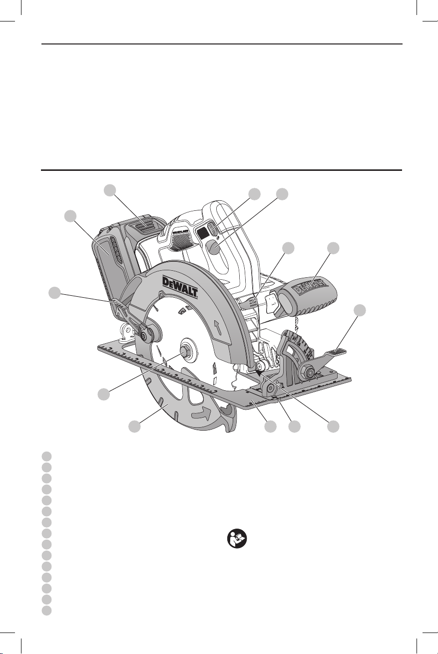
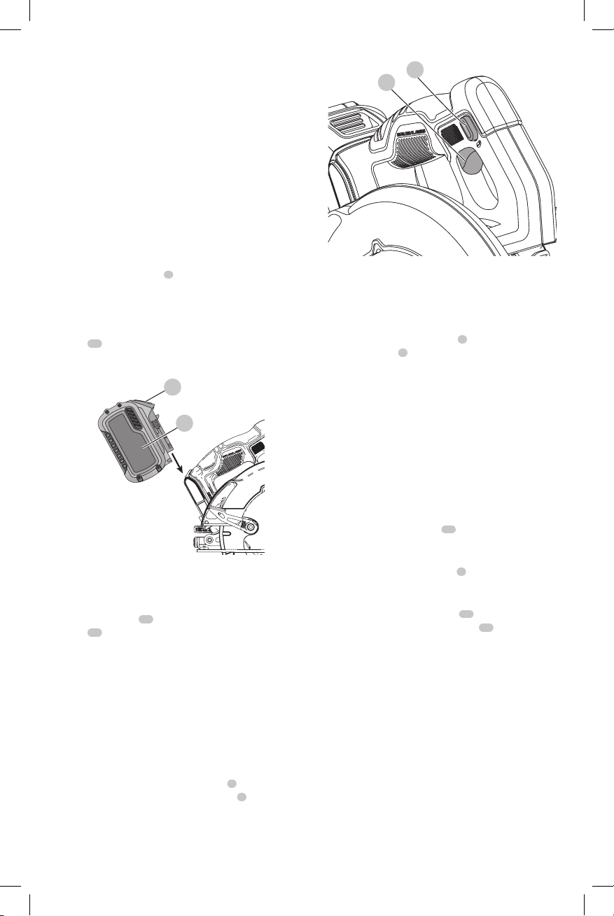
Fig. A
3
6
1
Trigger switch lock-off button
2
Trigger switch
3
Battery pack
4
Depth adjustment lever (Fig.H)
5
Shoe
6
Lower blade guard retracting lever
7
Lower blade guard
8
Blade clamping screw
9
Kerf indicator
10
Bevel adjustment lever
11
Blade lock button
12
Auxiliary handle
13
Battery release button
14
Blade wrench (Fig.H)
15
Worklight
13
8
1 2
1211
10
957
WARNING! Read all safety warnings and all
instructions. Failure to follow the warnings and
instructions may result in electric shock, fire and/or
seriousinjury.
WARNING: To reduce the risk of injury, read the
instructionmanual.
If you have any questions or comments about this or
any
1-800-4-
tool, call us toll free at:
(1-800-433-9258).
15
1
Page 4

ENGLISH
GENERAL POWER TOOL SAFETY WARNINGS
WARNING! Read all safety warnings and all
instructions. Failure to follow the warnings and
instructions may result in electric shock, fire and/or
seriousinjury.
SAVE ALL WARNINGS AND
INSTRUCTIONS FOR FUTURE
REFERENCE
The term “power tool” in the warnings refers to your mainsoperated (corded) power tool or battery-operated (cordless)
powertool.
1) Work Area Safety
a ) Keep work area clean and well lit. Cluttered or dark
areas inviteaccidents.
b ) Do not operate power tools in explosive
atmospheres, such as in the presence of
flammable liquids, gases or dust. Power tools
create sparks which may ignite the dust orfumes.
c ) Keep children and bystanders away while
operating a power tool. Distractions can cause you
to losecontrol.
2) Electrical Safety
a ) Power tool plugs must match the outlet. Never
modify the plug in any way. Do not use any
adapter plugs with earthed (grounded) power
tools. Unmodified plugs and matching outlets will
reduce risk of electricshock.
b ) Avoid body contact with earthed or grounded
surfaces such as pipes, radiators, ranges and
refrigerators. There is an increased risk of electric
shock if your body is earthed orgrounded.
c ) Do not expose power tools to rain or wet
conditions. Water entering a power tool will increase
the risk of electricshock.
d ) Do not abuse the cord. Never use the cord for
carrying, pulling or unplugging the power tool.
Keep cord away from heat, oil, sharp edges or
moving parts. Damaged or entangled cords increase
the risk of electricshock.
e ) When operating a power tool outdoors, use an
extension cord suitable for outdoor use. Use of
a cord suitable for outdoor use reduces the risk of
electricshock.
f ) If operating a power tool in a damp location
is unavoidable, use a ground fault circuit
interrupter (GFCI) protected supply. Use of a GFCI
reduces the risk of electricshock.
3) Personal Safety
a ) Stay alert, watch what you are doing and use
common sense when operating a power tool. Do
not use a power tool while you are tired or under
the influence of drugs, alcohol or medication. A
moment of inattention while operating power tools
may result in serious personalinjury.
b ) Use personal protective equipment. Always wear
eye protection. Protective equipment such as dust
mask, non-skid safety shoes, hard hat, or hearing
protection used for appropriate conditions will reduce
personalinjuries.
c ) Prevent unintentional starting. Ensure the
switch is in the off position before connecting to
power source and/or battery pack, picking up or
carrying the tool. Carrying power tools with your
finger on the switch or energizing power tools that
have the switch on invitesaccidents.
d ) Remove any adjusting key or wrench before
turning the power tool on. A wrench or a key left
attached to a rotating part of the power tool may
result in personalinjury.
e ) Do not overreach. Keep proper footing and
balance at all times. This enables better control of
the power tool in unexpectedsituations.
f ) Dress properly. Do not wear loose clothing or
jewelry. Keep your hair, clothing and gloves
away from moving parts. Loose clothes, jewelry or
long hair can be caught in movingparts.
g ) If devices are provided for the connection of dust
extraction and collection facilities, ensure these
are connected and properly used. Use of dust
collection can reduce dust-relatedhazards.
4) Power Tool Use and Care
a ) Do not force the power tool. Use the correct
power tool for your application. The correct power
tool will do the job better and safer at the rate for
which it wasdesigned.
b ) Do not use the power tool if the switch does not
turn it on and off. Any power tool that cannot be
controlled with the switch is dangerous and must
berepaired.
c ) Disconnect the plug from the power source and/
or the battery pack from the power tool before
making any adjustments, changing accessories,
or storing power tools. Such preventive safety
measures reduce the risk of starting the power
toolaccidentally.
d ) Store idle power tools out of the reach of children
and do not allow persons unfamiliar with the
power tool or these instructions to operate the
power tool. Power tools are dangerous in the hands
of untrainedusers.
e ) Maintain power tools. Check for misalignment or
binding of moving parts, breakage of parts and
any other condition that may affect the power
tool’s operation. If damaged, have the power
tool repaired before use. Many accidents are
caused by poorly maintained powertools.
f ) Keep cutting tools sharp and clean. Properly
maintained cutting tools with sharp cutting edges are
less likely to bind and are easier tocontrol.
g ) Use the power tool, accessories and tool bits, etc.
in accordance with these instructions, taking
2
Page 5

into account the working conditions and the
work to be performed. Use of the power tool for
operations different from those intended could result
in a hazardoussituation.
5) Battery Tool Use and Care
a ) Recharge only with the charger specified by the
manufacturer. A charger that is suitable for one type
of battery pack may create a risk of fire when used
with another batterypack.
b ) Use power tools only with specifically designated
battery packs. Use of any other battery packs may
create a risk of injury andfire.
c ) When battery pack is not in use, keep it away
from other metal objects, like paper clips, coins,
keys, nails, screws, or other small metal objects,
that can make a connection from one terminal to
another. Shorting the battery terminals together may
cause burns or afire.
d ) Under abusive conditions, liquid may be ejected from
the battery; avoid contact. If contact accidentally
occurs, flush with water. If liquid contacts eyes,
additionally seek medical help. Liquid ejected from
the battery may cause irritation orburns.
6) Service
a ) Have your power tool serviced by a qualified
repair person using only identical replacement
parts. This will ensure that the safety of the power
tool ismaintained.
Safety Instructions for All Saws
Cutting Procedures
a ) DANGER: Keep hands away from cutting
area and the blade. Keep your second hand on
auxiliary handle, or motor housing. If both hands
are holding the saw, they cannot be cut by the blade.
b ) Do not reach underneath the workpiece. The
guard cannot protect you from the blade below the
workpiece.
c ) Adjust the cutting depth to the thickness of the
workpiece. Less than a full tooth of the blade teeth
should be visible below the workpiece.
d ) Never hold piece being cut in your hands or
across your leg. Secure the workpiece to a stable
platform. It is important to support the work properly
to minimize body exposure, blade binding, or loss of
control.
e ) Hold power tool by insulated gripping surfaces
when performing an operation where the cutting
tool may contact hidden wiring. Contact with a
“live” wire will also make exposed metal parts of the
power tool “live” and shock the operator.
f ) When ripping always use a rip fence or straight
edge guide. This improves the accuracy of cut and
reduces the chance of blade binding.
g ) Always use blades with correct size and shape
(diamond versus round) of arbor holes. Blades
ENGLISH
that do not match the mounting hardware of the saw
will run eccentrically, causing loss of control.
h ) Never use damaged or incorrect blade washers
or bolt. The blade washers and bolt were specially
designed for your saw, for optimum performance and
safety of operation.
Further Safety Instructions for All Saws
Causes and Operator Prevention of
Kickback:
ʵ Kickback is a sudden reaction to a pinched, bound or
misaligned saw blade, causing an uncontrolled saw to
lift up and out of the workpiece toward the operator;
ʵ When the blade is pinched or bound tightly by the kerf
closing down, the blade stalls and the motor reaction
drives the unit rapidly back toward the operator;
ʵ If the blade becomes twisted or misaligned in the cut,
the teeth at the back edge of the blade can dig into
the top surface of the wood causing the blade to climb
out of the kerf and jump back toward the operator.
Kickback is the result of saw misuse and/or incorrect operating
procedures or conditions and can be avoided by taking proper
precautions as given below:
a ) Maintain a firm grip with both hands on the saw
and position your arms to resist kickback forces.
Position your body to either side of the blade,
but not in line with the blade. Kickback could cause
the saw to jump backwards, but kickback forces can
be controlled by the operator, if proper precautions
are taken.
b ) When blade is binding, or when interrupting a
cut for any reason, release the trigger and hold
the saw motionless in the material until the
blade comes to a complete stop. Never attempt
to remove the saw from the work or pull the
saw backward while the blade is in motion or
kickback may occur. Investigate and take corrective
actions to eliminate the cause of blade binding.
c ) When restarting a saw in the workpiece, center
the saw blade in the kerf and check that saw
teeth are not engaged into the material. If saw
blade is binding, it may walk up or kickback from the
workpiece as the saw is restarted.
d ) Support large panels to minimize the risk of
blade pinching and kickback. Large panels tend
to sag under their own weight. Supports must be
placed under the panel on both sides, near the line of
cut and near the edge of the panel.
e ) Do not use dull or damaged blades. Unsharpened
or improperly set blades produce narrow kerf causing
excessive friction, blade binding and kickback.
f ) Blade depth and bevel adjusting locking levers
must be tight and secure before making cut. If
blade adjustment shifts while cutting, it may cause
binding and kickback.
g ) Use extra caution when making a “plunge cut”
into existing walls or other blind areas. The
3
Page 6

ENGLISH
protruding blade may cut objects that can cause
kickback.
Lower Guard Function Safety
Instructions
a ) Check lower guard for proper closing before each
use. Do not operate the saw if lower guard does
not move freely and close instantly. Never clamp
or tie the lower guard into the open position. If
saw is accidentally dropped, lower guard may
be bent. Raise the lower guard with the retracting
handle and make sure it moves freely and does not
touch the blade or any other part, in all angles and
depths of cut.
b ) Check the operation of the lower guard spring.
If the guard and the spring are not operating
properly, they must be serviced before use. Lower
guard may operate sluggishly due to damaged parts,
gummy deposits, or a build-up of debris.
c ) Lower guard should be retracted manually
only for special cuts such as “plunge cuts”
and “compound cuts.” Raise lower guard by
retracting handle and as soon as blade enters
the material, the lower guard must be released.
For all other sawing, the lower guard should operate
automatically.
d ) Always observe that the lower guard is covering
the blade before placing saw down on bench or
floor. An unprotected, coasting blade will cause
the saw to walk backwards, cutting whatever is
in its path. Be aware of the time it takes for the blade
to stop after switch is released.
Additional Safety Information
WARNING: ALWAYS use safety glasses. Everyday
eyeglasses are NOT safety glasses. Also use face or
dust mask if cutting operation is dusty. ALWAYS WEAR
CERTIFIED SAFETYEQUIPMENT:
• ANSI Z87.1 eye protection (CAN/CSA Z94.3),
• ANSI S12.6 (S3.19) hearing protection,
• NIOSH/OSHA/MSHA respiratoryprotection.
WARNING: Some dust created by power sanding,
sawing, grinding, drilling, and other construction
activities contains chemicals known to the State
of California to cause cancer, birth defects or
other reproductive harm. Some examples of these
chemicalsare:
• lead from lead-based paints,
• crystalline silica from bricks and cement and other
masonry products, and
• arsenic and chromium from chemicallytreatedlumber.
Your risk from these exposures varies, depending on how
often you do this type of work. To reduce your exposure to
these chemicals: work in a well ventilated area, and work with
approved safety equipment, such as those dust masks that are
specially designed to filter out microscopicparticles.
• Avoid prolonged contact with dust from power
sanding, sawing, grinding, drilling, and other
construction activities. Wear protective clothing and
wash exposed areas with soap and water. Allowing
dust to get into your mouth, eyes, or lay on the skin may
promote absorption of harmfulchemicals.
WARNING: Use of this tool can generate and/
or disperse dust, which may cause serious and
permanent respiratory or other injury. Always use
NIOSH/OSHA approved respiratory protection
appropriate for the dust exposure. Direct particles
away from face andbody.
WARNING: Always wear proper personal hearing
protection that conforms to ANSI S12.6 (S3.19)
during use. Under some conditions and duration
of use, noise from this product may contribute to
hearingloss.
CAUTION: When not in use, place tool on its side
on a stable surface where it will not cause a
tripping or falling hazard. Some tools with large
battery packs will stand upright on the battery pack
but may be easily knockedover.
WARNING: Do not use abrasive wheels or blades.
WARNING: Do not use water feed attachments.
• Use clamps or another practical way to secure and
support the workpiece to a stable platform. Holding the
work by hand or against your body leaves it unstable and
may lead to loss of control.
• Keep your body positioned to either side of the
blade, but not in line with the saw blade. KICKBACK
could cause the saw to jump backwards (see Causes and
Operator Prevention of Kickback and KICKBACK).
• Air vents often cover moving parts and should be
avoided. Loose clothes, jewelry or long hair can be
caught in moving parts.
• Avoid cutting nails. Inspect for and remove all nails from
lumber before cutting.
The label on your tool may include the following symbols. The
symbols and their definitions are asfollows:
V ......................... volts
Hz ....................... hertz
min ..................... minutes
or DC ......direct current
...................... Class I Construction
(grounded)
…/min .............. per minute
BPM .................... beats per minute
IPM ..................... impacts per minute
RPM .................... revolutions per
minute
sfpm ................... surface feet per
minute
SPM .................... strokes per minute
A ......................... amperes
W ........................ watts
or AC ........... alternating current
or AC/DC .... alternating or
direct current
...................... Class II
Construction
(double insulated)
no ....................... no load speed
n ......................... rated speed
...................... earthing terminal
..................... safety alert symbol
..................... visible radiation
4
Page 7
..................... wear respiratory
DeWALT
DeWALT
DeWALT
protection
..................... wear eye
protection
..................... wear hearing
protection
..................... read all
documentation
BATTERIES AND CHARGERS
The battery pack is not fully charged out of the carton.
Before using the battery pack and charger, read the
safety instructions below and then follow charging
proceduresoutlined. When ordering replacement battery
packs, be sure to include the catalog number andvoltage.
Your tool uses a
instructions before using your charger. Consult the chart
at the end of this manual for compatibility of chargers and
batterypacks.
charger. Be sure to read all safety
READ ALL INSTRUCTIONS
Important Safety Instructions for All
Battery Packs
WARNING: Read all safety warnings and all
instructions for the battery pack, charger and
power tool. Failure to follow the warnings and
instructions may result in electric shock, fire and/
or serious injury.
• Do not charge or use the battery pack in explosive
atmospheres, such as in the presence of flammable
liquids, gases or dust. Inserting or removing the battery
pack from the charger may ignite the dust orfumes.
• NEVER force the battery pack into the charger. DO
NOT modify the battery pack in any way to fit into
a non-compatible charger as battery pack may
rupture causing serious personal injury. Consult
the chart at the end of this manual for compatibility of
batteries andchargers.
• Charge the battery packs only in designated
• DO NOT splash or immerse in water or otherliquids.
• Do not store or use the tool and battery pack in
• Do not incinerate the battery pack even if it is
• If battery contents come into contact with the skin,
chargers.
locations where the temperature may reach or
exceed 104°F (40°C) (such as outside sheds or metal
buildings in summer). For best life store battery packs in
a cool, drylocation.
NOTE: Do not store the battery packs in a tool with
the trigger switch locked on. Never tape the trigger
switch in the ONposition.
severely damaged or is completely worn out. The
battery pack can explode in a fire. Toxic fumes and
materials are created when lithium ion battery packs
areburned.
immediately wash area with mild soap and water. If
battery liquid gets into the eye, rinse water over the open
eye for 15 minutes or until irritation ceases. If medical
attention is needed, the battery electrolyte is composed of
a mixture of liquid organic carbonates and lithiumsalts.
ENGLISH
• Contents of opened battery cells may cause
respiratory irritation. Provide fresh air. If symptoms
persist, seek medicalattention.
WARNING: Burn hazard. Battery liquid may be
flammable if exposed to spark orflame.
WARNING: Fire hazard. Never attempt to open the
battery pack for any reason. If the battery pack case
is cracked or damaged, do not insert into the charger.
Do not crush, drop or damage the battery pack. Do
not use a battery pack or charger that has received a
sharp blow, been dropped, run over or damaged in
any way (e.g., pierced with a nail, hit with a hammer,
stepped on). Damaged battery packs should be
returned to the service center forrecycling.
Transportation
WARNING: Fire hazard. Do not store or carry the
battery pack so that metal objects can contact
exposed battery terminals. For example, do
not place the battery pack in aprons, pockets, tool
boxes, product kit boxes, drawers, etc., with loose
nails, screws, keys, etc. Transporting batteries
can possibly cause fires if the battery terminals
inadvertently come in contact with conductive
materials such as keys, coins, hand tools and the
like. The US Department of Transportation Hazardous
Material Regulations (HMR) actually prohibit
transporting batteries in commerce or on airplanes in
carry-on baggage UNLESS they are properly protected
from short circuits. So when transporting individual
battery packs, make sure that the battery terminals
are protected and well insulated from materials that
could contact them and cause a short circuit.
Shipping the
The DeWALT FLEXVOLT™ battery has two modes: Use and
Shipping.
Use Mode: When the FLEXVOLT™ battery stands alone or is
in a DeWALT 20V Max* product, it will operate as a 20V Max*
battery. When the FLEXVOLT™ battery is in a 60V Max* or a
120V Max* (two 60V Max* batteries) product, it will operate
as a 60V Max* battery.
Shipping Mode: When
the cap is attached to the
FLEXVOLT™ battery, the
battery is in Shipping Mode.
Strings of cells are electrically
disconnected within the pack resulting in three batteries
with a lower Watt hour (Wh) rating as compared to one
battery with a higher Watt hour rating. This increased
quantity of three batteries with the lower Watt hour rating
can exempt the pack from certain shipping regulations that
are imposed upon the higher Watt hour batteries.
The battery label indicates two Watt hour ratings (see
example). Depending on how the battery is shipped, the
appropriate Watt hour rating must be used to determine
the applicable shipping requirements. If utilizing the
shipping cap, the pack will be considered 3 batteries at
the Watt hour rating indicated for “Shipping”. If shipping
FLEXVOLT™ Battery
5
Page 8
ENGLISH
DeWALT
DeWALT
DeWALT
DeWALT
DeWALT
DeWALT
without the cap or in a tool, the pack will be considered one
battery at the Watt hour rating indicated next to “Use”.
Example of Use and Shipping Label Marking
USE: 120 Wh Shipping: 3 x 40 Wh
For example, Shipping Wh rating might indicate 3 x 40 Wh,
meaning 3 batteries of 40 Watt hours each. The Use Wh
rating might indicate 120 Wh (1 battery implied).
Fuel Gauge Battery Packs (Fig. B)
Some
consists of three green LED lights that indicate the level of
charge remaining in the batterypack.
The fuel gauge is an indication of approximate levels of
charge remaining in the battery pack according to the
followingindicators:
To actuate the fuel gauge, press and hold the fuel gauge
button. A combination of the three green LED lights will
illuminate designating the level of charge left. When the
level of charge in the battery is below the usable limit, the
fuel gauge will not illuminate and the battery will need to
berecharged.
NOTE: The fuel gauge is only an indication of the charge left
on the battery pack. It does not indicate tool functionality
and is subject to variation based on product components,
temperature and end-userapplication.
For more information regarding fuel gauge battery packs,
please contact call 1-800-4visit our website www.dewalt.com.
battery packs include a fuel gauge which
75–100% charged
51–74% charged
< 50% charged
Pack needs to be charged
Fig. B
(1-800-433-9258) or
The RBRC® Seal
The RBRC® (Rechargeable Battery
Recycling Corporation) Seal on the nickel
cadmium, nickel metal hydride or lithiumion batteries (or battery packs) indicates
that the costs to recycle these batteries
(or battery packs) at the end of their useful life have already
been paid by
spent nickel cadmium, nickel metal hydride or lithium-ion
batteries in the trash or municipal solid waste stream and
the Call2Recycle® program provides an environmentally
consciousalternative.
Call 2 Recycle, Inc., in cooperation with
battery users, has established the program in the United
States and Canada to facilitate the collection of spent nickel
cadmium, nickel metal hydride or lithium-ion batteries. Help
6
. In some areas, it is illegal to place
and other
protect our environment and conserve natural resources by
returning the spent nickel cadmium, nickel metal hydride
or lithium-ion batteries to an authorized
center or to your local retailer for recycling. You may also
contact your local recycling center for information on
where to drop off the spent battery. RBRC® is a registered
trademark of Call 2 Recycle,Inc.
service
Important Safety Instructions for All
Battery Chargers
WARNING: Read all safety warnings and all
instructions for the battery pack, charger and
power tool. Failure to follow the warnings and
instructions may result in electric shock, fire and/
or serious injury.
• DO NOT attempt to charge the battery pack with
any chargers other than the ones in this manual.
The charger and battery pack are specifically designed to
worktogether.
• These chargers are not intended for any uses other
than charging
Any other uses may result in risk of fire, electric shock
orelectrocution.
• Do not expose the charger to rain orsnow.
• Pull by the plug rather than the cord when
disconnecting the charger. This will reduce the risk of
damage to the electric plug andcord.
• Make sure that the cord is located so that it will not
be stepped on, tripped over or otherwise subjected
to damage orstress.
• Do not use an extension cord unless it is absolutely
necessary. Use of improper extension cord could result in
risk of fire, electric shock orelectrocution.
• When operating a charger outdoors, always provide
a dry location and use an extension cord suitable
for outdoor use. Use of a cord suitable for outdoor use
reduces the risk of electricshock.
• An extension cord must have adequate wire size
(AWG or American Wire Gauge) for safety. The smaller
the gauge number of the wire, the greater the capacity
of the cable, that is, 16 gauge has more capacity than 18
gauge. An undersized cord will cause a drop in line voltage
resulting in loss of power and overheating. When using
more than one extension to make up the total length,
be sure each individual extension contains at least the
minimum wire size. The following table shows the correct
size to use depending on cord length and nameplate
ampere rating. If in doubt, use the next heavier gauge. The
lower the gauge number, the heavier thecord.
rechargeable batteries.
Page 9
Minimum Gauge for Cord Sets
DeWALT
Volts
120 V 25 (7.6) 50 (15.2) 100 (30.5) 150 (45.7)
240 V 50 (15.2) 100 (30.5) 200 (61.0) 300 (91.4)
Ampere Rating
More
Not
Than
More
Than
0 6 18 16 16 14
6 10 18 16 14 12
10 12 16 16 14 12
12 16 14 12 Not Recommended
• Do not place any object on top of the charger or
place the charger on a soft surface that might block
the ventilation slots and result in excessive internal
heat. Place the charger in a position away from any heat
source. The charger is ventilated through slots in the top
and the bottom of thehousing.
• Do not operate the charger with a damaged cord
orplug.
• Do not operate the charger if it has received a sharp
blow, been dropped or otherwise damaged in any
way. Take it to an authorized servicecenter.
• Do not disassemble the charger; take it to an
authorized service center when service or repair
is required. Incorrect reassembly may result in a risk of
electric shock, electrocution orfire.
• Disconnect the charger from the outlet before
attempting any cleaning. This will reduce the risk of
electric shock. Removing the battery pack will not reduce
thisrisk.
• NEVER attempt to connect 2 chargerstogether.
• The charger is designed to operate on standard
120V household electrical power. Do not attempt to
use it on any other voltage. This does not apply to the
vehicularcharger.
WARNING: Shock hazard. Do not allow any liquid to
get inside the charger. Electric shock mayresult.
WARNING: Burn hazard. Do not submerge the
battery pack in any liquid or allow any liquid to
enter the battery pack. Never attempt to open the
battery pack for any reason. If the plastic housing of
the battery pack breaks or cracks, return to a service
center for recycling.
CAUTION: Burn hazard. To reduce the risk of injury,
charge only
Other types of batteries may overheat and burst
resulting in personal injury and propertydamage.
NOTICE: Under certain conditions, with the charger
plugged into the power supply, the charger can
be shorted by foreign material. Foreign materials
of a conductive nature, such as, but not limited to,
grinding dust, metal chips, steel wool, aluminum
foil or any buildup of metallic particles should be
kept away from the charger cavities. Always unplug
the charger from the power supply when there is no
Total Length of Cord in Feet
(meters)
American Wire Gauge
rechargeable battery packs.
ENGLISH
battery pack in the cavity. Unplug the charger before
attempting toclean.
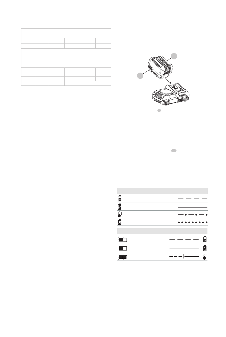
Charging a Battery (Fig. C)
1. Plug the charger into an appropriate outlet before
inserting battery pack.
Fig. C
13
2. Insert the battery pack
the battery pack is fully seated in the charger. The red
(charging) light will blink continuously indicating that
the charging process has started.
3. The completion of charge will be indicated by the red
light remaining ON continuously. The battery pack is
fully charged and may be used at this time or left in the
charger. To remove the battery pack from the charger,
push the battery release button
NOTE: To ensure maximum performance and life of lithiumion battery packs, charge the battery pack fully before first
use.
3
Charger Operation
Refer to the indicators below for the charge status of the
battery pack.
DCB101
Charging
Fully Charged
Hot/Cold Pack Delay
Problem Pack or Charger
DCB107, DCB112, DCB113, DCB115, DCB118, DCB132
Charging
Fully Charged
Hot/Cold Pack Delay*
* DCB107, DCB112, DCB113, DCB115, DCB118, DCB132:
The red light will continue to blink, but a yellow indicator
light will be illuminated during this operation. Once the
battery pack has reached an appropriate temperature, the
yellow light will turn off and the charger will resume the
charging procedure.
The compatible charger(s) will not charge a faulty battery
pack. The charger will indicate faulty battery pack by
refusing to light or by displaying a problem pack or charger
blink pattern.
3
into the charger, making sure
13
on the battery pack.
7
Page 10

ENGLISH
NOTE: This could also mean a problem with a charger.
If the charger indicates a problem, take the charger and
battery pack to be tested at an authorized service center.
Hot/Cold Pack Delay
When the charger detects a battery pack that is too hot
or too cold, it automatically starts a Hot/Cold Pack Delay,
suspending charging until the battery pack has reached an
appropriate temperature. The charger then automatically
switches to the pack charging mode. This feature ensures
maximum battery pack life.
A cold battery pack will charge at a slower rate than a warm
battery pack. The battery pack will charge at that slower rate
throughout the entire charging cycle and will not return to
maximum charge rate even if the battery pack warms.
The DCB118 charger is equipped with an internal fan
designed to cool the battery pack. The fan will turn on
automatically when the battery pack needs to be cooled.
Never operate the charger if the fan does not operate
properly or if ventilation slots are blocked. Do not permit
foreign objects to enter the interior of the charger.
Electronic Protection System
Li-Ion tools are designed with an Electronic Protection
System that will protect the battery pack against
overloading, overheating or deep discharge.
The tool will automatically turn off if the Electronic
Protection System engages. If this occurs, place the lithiumion battery pack on the charger until it is fully charged.
Wall Mounting
DCB107, DCB112, DCB113, DCB115, DCB118, DCB132
These chargers are designed to be wall mountable or to
sit upright on a table or work surface. If wall mounting,
locate the charger within reach of an electrical outlet,
and away from a corner or other obstructions which may
impede air flow. Use the back of the charger as a template
for the location of the mounting screws on the wall. Mount
the charger securely using drywall screws (purchased
separately) at least 1" (25.4 mm) long, with a screw head
diameter of 0.28–0.35" (7–9mm), screwed into wood to an
optimal depth leaving approximately 7/32" (5.5 mm) of the
screw exposed. Align the slots on the back of the charger
with the exposed screws and fully engage them in the slots.
Charger Cleaning Instructions
WARNING: Shock hazard. Disconnect the charger
from the AC outlet before cleaning. Dirt and grease
may be removed from the exterior of the charger using
a cloth or soft non-metallic brush. Do not use water or
any cleaning solutions.
Important Charging Notes
1. Longest life and best performance can be obtained if
the battery pack is charged when the air temperature is
between 65°F and 75°F (18° – 24°C). DO NOT charge
the battery pack in an air temperature below +40°F
(+4.5°C), or above +104°F (+40°C). This is important
and will prevent serious damage to the battery pack.
2. The charger and battery pack may become warm to the
touch while charging. This is a normal condition, and
does not indicate a problem. To facilitate the cooling of
the battery pack after use, avoid placing the charger or
battery pack in a warm environment such as in a metal
shed or an uninsulated trailer.
3. If the battery pack does not charge properly:
a. Check operation of receptacle by plugging in a lamp
or other appliance;
b. Check to see if receptacle is connected to a light
switch which turns power off when you turn out the
lights;
c. Move the charger and battery pack to a location
where the surrounding air temperature is
approximately 65°F – 75°F (18° – 24°C);
d. If charging problems persist, take the tool, battery
pack and charger to your local service center.
4. The battery pack should be recharged when it fails to
produce sufficient power on jobs which were easily
done previously. DO NOT CONTINUE to use under these
conditions. Follow the charging procedure. You may
also charge a partially used pack whenever you desire
with no adverse effect on the battery pack.
5. Foreign materials of a conductive nature such as, but
not limited to, grinding dust, metal chips, steel wool,
aluminum foil, or any buildup of metallic particles
should be kept away from charger cavities. Always
unplug the charger from the power supply when there
is no battery pack in the cavity. Unplug the charger
before attempting to clean.
6. Do not freeze or immerse the charger in water or any
other liquid.
Storage Recommendations
1. The best storage place is one that is cool and dry, away
from direct sunlight and excess heat or cold.
2. For long storage, it is recommended to store a fully
charged battery pack in a cool dry place out of the
charger for optimal results.
NOTE: Battery packs should not be stored completely
depleted of charge. The battery pack will need to be
recharged before use.
SAVE THESE INSTRUCTIONS FOR
FUTURE USE
COMPONENTS (FIG. A)
WARNING: Never modify the power tool or any part
of it. Damage or personal injury couldresult.
Refer to Figure A at the beginning of this manual for a
complete list ofcomponents.
INTENDED USE
This heavy-duty circular saw is designed for professional
wood cutting applications. Do not cut metal, plastic,
concrete, masonry or fiber cement materials.
DO NOT use under wet conditions or in presence of
flammable liquids orgases.
8
Page 11
DO NOT let children come into contact with the tool.
Supervision is required when inexperienced operators use
thistool.
OPERATION
WARNING: To reduce the risk of serious personal
injury, turn unit off and remove the battery pack
before making any adjustments or removing/
installing attachments or accessories. An
accidental start-up can causeinjury.
Installing and Removing the Battery Pack
(Fig. D)
NOTE: For best results, make sure your battery pack is
fullycharged.
To install the battery pack
battery pack with the rails inside the tool’s handle and slide
it into the handle until the battery pack is firmly seated in
the tool and ensure that it does notdisengage.
To remove the battery pack from the tool, press the release
13
button
handle. Insert it into the charger as described in the charger
section of thismanual.
and firmly pull the battery pack out of the tool
Fig. D
3
into the tool handle, align the
13
3
Worklight (Fig. A)
CAUTION: Do not stare into worklight. Serious eye
injury could result.
There is a worklight
11
button
switch is depressed, and will automatically turn off 20
seconds after the trigger switch is released. If the trigger
switch remains depressed, the worklight will remain on.
NOTE: The worklight is for lighting the immediate work
surface and is not intended to be used as a flashlight.
15
. The worklight is activated when the trigger
located just below the blade lock
Trigger Switch (Fig. E)
WARNING: This tool has no provision to lock the
trigger switch in the ON position and should never be
locked ON by any other means.
Release the trigger switch lock-off button
the button as shown. Pull the trigger switch
motor on. Releasing the trigger switch turns the motor off.
1
by pressing
2
to turn the
ENGLISH
Fig. E
1
2
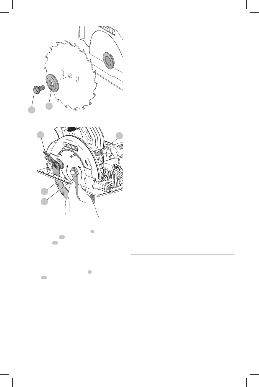
Changing Blades (Fig. F, G, H)
WARNING: Remove battery from tool before
changing blades.
To install the Blade (Fig. F, G, H)
1. Retract the lower blade guard
retracting lever
spindle against the inner clamp washer, making sure
that the blade will rotate in the proper direction (the
direction of the rotation arrow on the saw blade and the
teeth must point in the same direction as the direction
of rotation arrow on the lower blade guard). Do not
assume that the printing on the blade will always be
facing you when properly installed. When retracting
the lower blade guard to install the blade, check the
condition and operation of the lower blade guard to
assure that it is working properly. Make sure it moves
freely and does not touch the blade or any other part, in
all angles and depths of cut.
2. Place outer clamp washer
large flat surface against the blade with beveled side
facing out.
3. Thread blade clamping screw
hand (screw has right-hand threads and must be turned
clockwise to tighten).
4. Depress the blade lock button
saw spindle with the blade wrench
lock engages and the blade stops rotating (Fig.G).
5. Tighten the blade clamping screw firmly with the blade
wrench.
NOTE: Never engage the blade lock while saw is running,
or engage in an effort to stop the tool. Never turn the saw
on while the blade lock is engaged. Serious damage to your
saw will result.
6
and place the blade on the saw
7
using the lower blade
16
on saw spindle with the
8
into saw spindle by
11
while turning the
14
until the blade
9
Page 12
ENGLISH
Fig. F
16
8
Fig. G
6
LOOSEN
(counterclockwise)
7
14
TIGHTEN
(clockwise)
To Replace the Blade (Fig. F, G)
1. To loosen the blade clamping screw
blade lock button
blade wrench
blade stops rotating. With the blade lock engaged, turn
the blade clamping screw counterclockwise with the
blade wrench (screw has right-hand threads and must
be turned counterclockwise to loosen).
2. Remove the blade clamping screw
16
washer
3. Clean any sawdust that may have accumulated in the
guard or clamp washer area and check the condition
and operation of the lower blade guard as previously
outlined. Do not lubricate this area.
4. Select the proper blade for the application (see
Blades). Always use blades that are the correct size
(diameter) with the proper size and shape center hole
for mounting on the saw spindle. Always assure that the
maximum recommended speed (rpm) on the saw blade
meets or exceeds the speed (rpm) of the saw.
5. Follow steps 2 through 5 under To Install the Blade,
making sure that the blade will rotate in the proper
direction.
10
11
and turn the saw spindle with the
14
until the blade lock engages and the
only. Remove old blade.
8
, depress the
8
and outer clamp
Lower Blade Guard
WARNING: The lower blade guard is a safety
feature which reduces the risk of serious
personal injury. Never use the saw if the lower
blade guard is missing, damaged, misassembled
or not working properly. Do not rely on the
lower blade guard to protect you under all
circumstances. Your safety depends on following
all warnings and precautions as well as proper
operation of the saw. Check lower blade guard
for proper closing before each use as outlined
in Further Safety Instructions for All Saws.
If the lower blade guard is missing or not
working properly, have the saw serviced before
using. To assure product safety and reliability,
repair, maintenance and adjustment should
be performed by an authorized service center
or other qualified service organization, always
11
using identical replacement parts.
Blades
WARNING: To minimize the risk of eye injury, always
use eye protection. Carbide is a hard but brittle
material. Foreign objects in the workpiece such as wire
or nails can cause tips to crack or break. Only operate
saw when proper saw blade guard is in place. Mount
blade securely in proper rotation before using, and
always use a clean, sharp blade.
WARNING: Do not cut metal, plastic, concrete,
masonry or fiber cement materials with this saw.
Do not use abrasive wheels or blades. A dull blade will
cause slow inefficient cutting, overload on the saw motor,
excessive splintering, and could increase the possibility of
kickback. Please refer to the table below to determine the
correct size replacement blade for your model saw.
RECOMMENDED BLADE TYPES
Combination Framing 5/8" Round arbor, 24 teeth
Pressure Treated/Wet
Lumber
Extreme Durability 5/8" Round arbor, 18 teeth
Finishing 5/8" Round arbor, 36 teeth
Fast Cut Framing 5/8" round arbor, 18 teeth
If you need assistance regarding blades, please call
1–800–4-DeWALT (1–800–433–9258).
Kickback
Kickback is a sudden reaction to a pinched, bound or
misaligned saw blade, causing an uncontrolled saw to lift
up and out of the workpiece toward the operator. When
the blade is pinched or bound tightly by the kerf closing
All purpose fast rip and cross
cuts.
5/8" Round arbor, 20 teeth
Coated, resistant to gum
build-up
Coated, rock carbide
More teeth for finer finish cuts.
Fastest blade for rips and cross
cuts
Page 13
down, the blade stalls and the motor reaction drives the
unit rapidly back toward the operator. If the blade becomes
twisted or misaligned in the cut, the teeth at the back
edge of the blade can dig into the top surface of the wood
causing the blade to climb out of the kerf and jump back
toward the operator.
Kickback is more likely to occur when any of the following
conditions exists.
1. IMPROPER WORKPIECE SUPPORT
a. Sagging or improper lifting of the cut off piece can
cause pinching of the blade and lead to kickback.
b. Cutting through material supported at the outer ends
only can cause kickback. As the material weakens it
sags, closing down the kerf and pinching the blade
(Fig.O).
c. Cutting off a cantilevered or overhanging piece of
material from the bottom up in a vertical direction
can cause kickback. The falling cut off piece can
pinch the blade.
d. Cutting off long narrow strips (as in ripping) can
cause kickback. The cut off strip can sag or twist
closing the kerf and pinching the blade.
e. Snagging the lower guard on a surface below the
material being cut momentarily reduces operator
control. The saw can lift partially out of the cut
increasing the chance of blade twist.
2. IMPROPER DEPTH OF CUT SETTING ON SAW
a. To make the most efficient cut, the blade should
protrude only far enough to expose one-half of
a tooth as shown in FigureI. This allows the shoe
to support the blade and minimizes twisting and
pinching in the material. See the section titled
Cutting Depth Adjustment.
3. BLADE TWISTING (MISALIGNMENT IN CUT)
a. Pushing harder to cut through a knot, a nail or a hard
grain area can cause the blade to twist.
b. Trying to turn the saw in the cut (trying to get back
on the marked line) can cause blade twist.
c. Overreaching or operating the saw with poor body
control (out of balance), can result in twisting the
blade.
d. Changing hand grip or body position while cutting
can result in blade twist.
e. Backing up the saw to clear blade can lead to twist.
4. MATERIALS THAT REQUIRE EXTRA ATTENTION
a. Wet lumber
b. Green lumber (material freshly cut or not kiln dried)
c. Pressure treated lumber (material treated with
preservatives or anti-rot chemicals)
5. USE OF DULL OR DIRTY BLADES
a. Dull blades cause increased loading of the saw. To
compensate, an operator will usually push harder
which further loads the unit and promotes twisting
of the blade in the kerf. Worn blades may also have
insufficient body clearance which increases the
chance of binding and increased loading.
ENGLISH
6. LIFTING THE SAW WHEN MAKING A BEVEL CUT
a. Bevel cuts require special operator attention to
proper cutting techniques – especially guidance of
the saw. Both blade angle to the shoe and greater
blade surface in the material increase the chance for
binding and misalignment (twist) to occur.
7. RESTARTING A CUT WITH THE BLADE TEETH
JAMMED AGAINST THE MATERIAL
a. The saw should be brought up to full operating
speed before starting a cut or restarting a cut after
the unit has been stopped with the blade in the kerf.
Failure to do so can cause stalling and kickback.
Any other conditions which could result in pinching,
binding, twisting, or misalignment of the blade could cause
kickback. Refer to the sections Further Safety Instructions
for All Saws and Blades for procedures and techniques that
will minimize the occurrence of kickback.
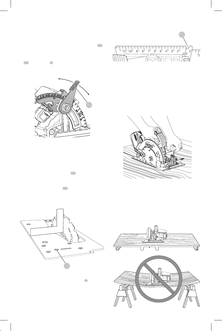
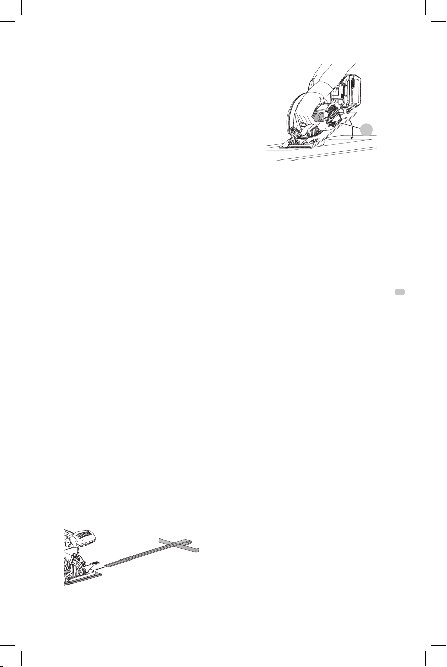
Cutting Depth Adjustment (Fig. A, H, I)
1. Hold the saw firmly and loosen (clockwise) the depth
adjustment lever
the desired depth of cut.
2. Make sure the depth adjustment lever has been
retightened (counterclockwise) before operating saw.
For the most efficient cutting action, set the depth
adjustment so that one-half tooth of the blade will project
below the material to be cut. This distance is from the tip of
the tooth to the bottom of the gullet in front of it. This keeps
blade friction at a minimum, removes sawdust from the cut,
results in cooler, faster sawing and reduces the chance of
kickback. A method for checking for correct cutting depth
is shown in FigureI. Lay a piece of the material you plan to
cut along the side of the blade, as shown, and observe how
much tooth projects beyond the material.
Fig. H
4
Fig. I
4
and move shoe (
5
, Fig.A) to obtain
14
11
Page 14
ENGLISH
Bevel Angle Adjustment (Fig. A, J)
The full range of the bevel adjustment is from 0° to 57°. The
quadrant is graduated in increments of 1°. On the front of
the saw is a bevel angle adjustment mechanism consisting
of a calibrated quadrant and a bevel adjustment lever
10
To set the saw for a bevel cut
1. Loosen (counterclockwise) the bevel adjustment lever
10
and tilt shoe (
aligning the pointer with the desired angle mark.
2. Retighten lever firmly (clockwise).
Fig. J
5
, Fig.A) to the desired angle by
10
Shoe Adjustment for 90°Cuts (Fig. J, K)
If additional adjustment is needed:
1. Adjust the saw to 0° bevel.
2. Retract the lower blade guard. Place the saw on blade
side.
3. Loosen bevel adjustment lever (
square against the blade and shoe to adjust the 90°
setting.
4. Turn the calibration screw
at the proper angle.
5. Confirm the accuracy of the setting by checking the
squareness of an actual cut on a scrap piece of material.
Fig. K
10
, Fig.J). Place a
17
so that the shoe will stop
penciled cutting line so that the kerf falls into the waste or
surplus material.
Fig. L
.
Workpiece Support (Fig. M–O)
WARNING: It is important to support the work
properly and to hold the saw firmly to prevent loss of
control which could cause personal injury. FigureM
illustrates proper hand support of the saw. Maintain
a firm grip with both hands on the saw and position
your body and arm to allow you to resist kickback
if it occurs. ALWAYS TURN OFF TOOL AND REMOVE
BATTERY BEFORE MAKING ANY ADJUSTMENTS!
Fig. M
Figure M shows proper sawing position. Note that hands
are kept away from cutting area. To avoid kickback, DO
support board or panel NEAR the cut (Fig.N). DON’T support
board or panel away from the cut (Fig.O).
Place the work with its “good” side – the one on which
appearance is most important – down. The saw cuts
upward, so any splintering will be on the work face that is
up when you cut it.
Fig. N
9
17
Kerf Indicator (Fig. L)
The front of the saw shoe has a kerf indicator
and bevel cutting. This indicator enables you to guide the
saw along cutting lines penciled on the material being cut.
The kerf indicator lines up with the left (inner) side of the
saw blade, which makes the slot or “kerf” cut by the moving
blade fall to the right of the indicator. Guide along the
12
9
for vertical
Fig. O
Page 15
Cutting (Fig. M)
DeWALT
Place the wider portion of the saw shoe on that part of the
workpiece which is solidly supported, not on the section
that will fall off when the cut is made. As an example,
FigureM illustrates the RIGHT way to cut off the end of a
board. Always clamp work. Don’t try to hold short pieces by
hand! Remember to support cantilevered and overhanging
material. Use caution when sawing material from below.
Be sure saw is up to full speed before blade contacts
material to be cut. Starting saw with blade against material
to be cut or pushed forward into kerf can result in kickback.
Push the saw forward at a speed which allows the blade to
cut without laboring.
Hardness and toughness can vary even in the same piece of
material, and knotty or damp sections can put a heavy load
on the saw. When this happens, push the saw more slowly,
but hard enough to keep working without much decrease
in speed. Forcing the saw can cause rough cuts, inaccuracy,
kickback, and over-heating of the motor.
Should your cut begin to go off the line, don’t try to force
it back on. Release the trigger switch and allow blade to
come to a complete stop. Then you can withdraw the saw,
sight anew, and start a new cut slightly inside the wrong
one. Withdraw the saw if you must shift the cut. Forcing
a correction inside the cut can stall the saw and lead to
kickback.
IF SAW STALLS, RELEASE THE TRIGGER SWITCH AND BACK
THE SAW UNTIL IT IS LOOSE. BE SURE BLADE IS STRAIGHT
IN THE CUT AND CLEAR OF THE CUTTING EDGE BEFORE
RESTARTING.
As you finish a cut, release the trigger switch and allow the
blade to stop before lifting the saw from the work. As you
lift the saw, the spring-tensioned lower blade guard will
automatically close under the blade. Remember the blade
is exposed until this occurs. Never reach under the work
for any reason. When you have to retract the lower blade
guard manually (as is necessary for starting pocket cuts),
always use the retracting lever.
WARNING: When cutting thin strips, be careful to
ensure that small cutoff pieces don’t hang up on the
inside of the lower blade guard.
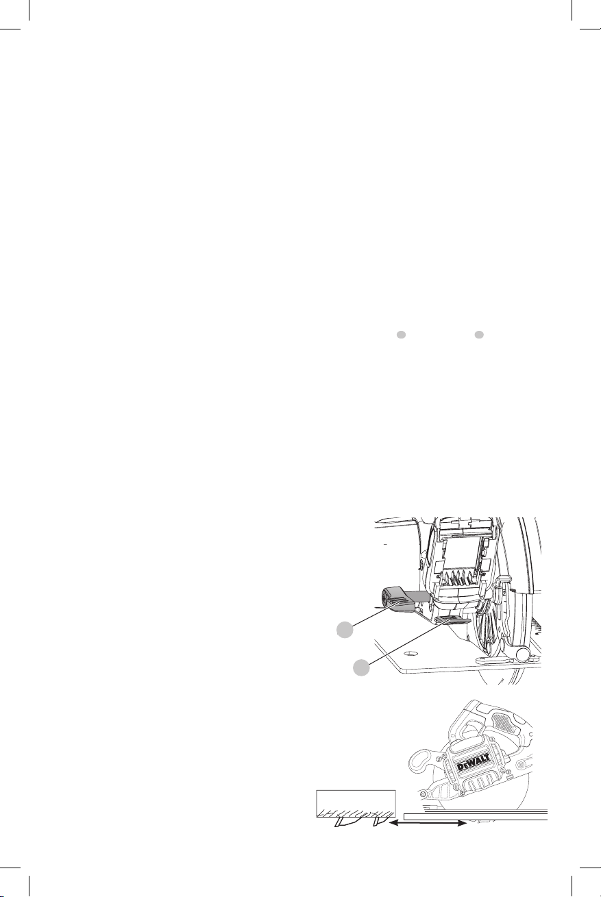
Ripping (Fig. P)
Ripping is the process of cutting wider boards into narrower
strips – cutting grain lengthwise. Hand guiding is more
difficult for this type of sawing and the use of a
fence is recommended.
Fig. P
Pocket Cutting (Fig. Q)
WARNING: Never tie the lower blade guard in a raised
position. Never move the saw backwards when pocket
rip
ENGLISH
cutting. This may cause the saw to raise up off the
work surface, which could cause injury.
Fig. Q
12
A pocket cut is one that is made in a floor, wall or other flat
surface.
1. Adjust the saw shoe so the blade cuts at desired depth.
2. Tilt the saw forward and rest front of the shoe on
material to be cut.
3. Using the lower blade guard retracting lever, retract the
lower blade guard to an upward position. Lower the
rear of the shoe until the blade teeth almost touch the
cutting line.
4. Release the lower blade guard (its contact with the work
will keep it in position to open freely as you start the
cut). Remove your hand from the lower blade guard
retracting lever and firmly grip the auxiliary handle
as shown in FigureQ. Position your body and arm to
allow you to resist kickback if it occurs.
5. Make sure blade is not in contact with cutting surface
before starting saw.
6. Start the motor and gradually lower the saw until its
shoe rests flat on the material to be cut. Advance saw
along the cutting line until cut is completed.
7. Release the trigger switch and allow the blade to stop
completely before withdrawing the blade from the
material.
8. When starting each new cut, repeat the above steps.
12
MAINTENANCE
WARNING: To reduce the risk of serious personal
injury, turn unit off and remove the battery pack
before making any adjustments or removing/
installing attachments or accessories. An
accidental start-up can causeinjury.
Cleaning
WARNING: Blow dirt and dust out of all air vents with
clean, dry air at least once a week. To minimize the risk
of eye injury, always wear ANSI Z87.1 approved eye
protection when performingthis.
WARNING: Never use solvents or other harsh
chemicals for cleaning the non-metallic parts of
the tool. These chemicals may weaken the plastic
materials used in these parts. Use a cloth dampened
only with water and mild soap. Never let any liquid
get inside the tool; never immerse any part of the tool
into aliquid.
,
13
Page 16

ENGLISH
DeWALT
DeWALT
DeWALT
DeWALT
DeWALT
DeWALT
DeWALT
DeWALT
DeWALT
DeWALT
DeWALT
DeWALT
DeWALT
Accessories
WARNING: Since accessories, other than those
offered by
product, use of such accessories with this tool could be
hazardous. To reduce the risk of injury, only
recommended accessories should be used with
thisproduct.
Recommended accessories for use with your tool
are available at extra cost from your local dealer or
authorized service center. If you need assistance in
locating any accessory, please contact
Tool Co., 701East Joppa Road, Towson, MD 21286, call
1-800-4www.dewalt.com.
, have not been tested with this
(1-800-433-9258) or visit our website:
Industrial
Repairs
The charger and battery pack are notserviceable.
WARNING: To assure product SAFETY and
RELIABILITY, repairs, maintenance and adjustment
(including brush inspection and replacement) should
be performed by a
or a
identical replacementparts.
authorized service center. Always use
factory service center
Register Online
Thank you for your purchase. Register your product nowfor:
• WARRANTY SERVICE: Registering your product will
help you obtain more efficient warranty service in case
there is a problem with yourproduct.
• CONFIRMATION OF OWNERSHIP: In case of
an insurance loss, such as fire, flood or theft, your
registration of ownership will serve as your proof
ofpurchase.
• FOR YOUR SAFETY: Registering your product will
allow us to contact you in the unlikely event a safety
notification is required under the Federal Consumer
SafetyAct.
Register online at www.dewalt.com/register.
2 YEARS FREE SERVICE ON DEWALT BATTERY PACKS
DC9071, DC9091, DC9096, DC9182, DC9280, DC9360, DCB120,
DCB127, DCB201, DCB203, DCB203BT, DCB207, DCB361
3 YEARS FREE SERVICE ON DEWALT BATTERY PACKS
DCB200, DCB204, DCB204BT, DCB205, DCB606
NOTE: Battery warranty voided if the battery pack is
tampered with in any way.
for any injury caused by tampering and may prosecute
warranty fraud to the fullest extent permitted bylaw.
90 DAY MONEY BACK GUARANTEE
If you are not completely satisfied with the performance of
your
can return it within 90 days from the date of purchase with
a receipt for a full refund – no questionsasked.
LATIN AMERICA: This warranty does not apply to products
sold in Latin America. For products sold in Latin America,
see country specific warranty information contained in
the packaging, call the local company or see website for
warrantyinformation.
FREE WARNING LABEL REPLACEMENT: If your warning
labels become illegible or are missing, call 1-800-4(1-800-433-9258) for a freereplacement.
Power Tool, Laser, or Nailer for any reason, you
is not responsible
Three Year Limited Warranty
will repair, without charge, any defects due to
faulty materials or workmanship for three years from the
date of purchase. This warranty does not cover part failure
due to normal wear or tool abuse. For further detail of
warranty coverage and warranty repair information, visit
www.dewalt.com or call 1-800-4This warranty does not apply to accessories or damage
caused where repairs have been made or attempted by
others. This warranty gives you specific legal rights and
you may have other rights which vary in certain states
orprovinces.
In addition to the warranty,
byour:
1 YEAR FREE SERVICE
will maintain the tool and replace worn parts
caused by normal use, for free, any time during the first year
afterpurchase.
14
(1-800-433-9258).
tools are covered
Page 17

Définitions : symboles et termes d'alarmes sécurité
DeWALT
DeWALT
Ces guides d'utilisation utilisent les symboles et termes d'alarmes sécurité suivants pour vous prévenir de situations
dangereuses et de risques de dommages corporels ou matériels.
DANGER: indique une situation dangereuse imminente qui, si elle n’est pas évitée, entraînera la mort ou des
blessuresgraves.
AVERTISSEMENT: indique une situation potentiellement dangereuse qui, si elle n’est pas évitée, pourrait entraîner la
mort ou des blessuresgraves.
ATTENTION: indique une situation potentiellement dangereuse qui, si elle n’est pas évitée, pourrait entraîner des
blessures légères oumodérées.
(Si utilisé sans aucun terme) Indique un message propre à la sécurité.
AVIS : indique une pratique ne posant aucun risque de dommages corporels mais qui par contre, si rien n’est fait
pour l’éviter, pourrait poser des risques de dommages matériels.
FRANÇAIS
Fig. A
3
6
1
Bouton de verrouillage de la gâchette
2
Interrupteur à gâchette
3
Bloc-piles
4
Levier de réglage de profondeur (Fig.H)
5
Patin
6
Levier rétractant du protège-lame inférieur
7
Protège-lame inférieur
8
Vis de fixation de la lame
9
Indicateur de trait de scie
10
Levier de réglage d’angle de biseau
11
Bouton de verrouillage de la lame
12
Poignée auxiliaire
13
Bouton de libération du bloc-piles
14
Clé pour lame (Fig.H)
15
Lampe de travail
13
8
1 2
1211
10
957
AVERTISSEMENT! lire tous les avertissements de
sécurité et toutes les directives. Le non-respect
des avertissements et des directives pourrait se
solder par un choc électrique, un incendie et/ou une
blessuregrave.
AVERTISSEMENT : afin de réduire le risque de
blessures, lire le mode d’emploi del’outil.
Pour toute question ou remarque au sujet de cet outil
ou de tout autre outil
sans frais : 1-800-4-
15
, composez le numéro
(1-800-433-9258).
15
Page 18

FRANÇAIS
AVERTISSEMENTS DE SÉCURITÉ GÉNÉRAUX
POUR LES OUTILS ÉLECTRIQUES
AVERTISSEMENT! lire tous les avertissements de
sécurité et toutes les directives. Le non-respect
des avertissements et des directives pourrait se
solder par un choc électrique, un incendie et/ou une
blessuregrave.
CONSERVER TOUS LES
AVERTISSEMENTS ET TOUTES
LES DIRECTIVES POUR UN USAGE
ULTÉRIEUR
Le terme « outil électrique » cité dans les avertissements se
rapporte à votre outil électrique à alimentation sur secteur
(avec fil) ou par piles (sans fil).
1) Sécurité du lieu de travail
a ) Tenir l’aire de travail propre et bien éclairée.
Les lieux encombrés ou sombres sont propices
auxaccidents.
b ) Ne pas faire fonctionner d’outils électriques
dans un milieu déflagrant, tel qu’en présence de
liquides, de gaz ou de poussières inflammables.
Les outils électriques produisent des étincelles qui
pourraient enflammer la poussière ou lesvapeurs.
c ) Éloigner les enfants et les personnes à proximité
pendant l’utilisation d’un outil électrique. Une
distraction pourrait en faire perdre la maîtrise à
l’utilisateur.
2) Sécurité en matière d’électricité
a ) Les fiches des outils électriques doivent
correspondre à la prise. Ne jamais modifier la
fiche d’aucune façon. Ne jamais utiliser de fiche
d’adaptation avec un outil électrique mis à la
terre. Le risque de choc électrique sera réduit par
l’utilisation de fiches non modifiées correspondant à
laprise.
b ) Éviter tout contact physique avec des surfaces
mises à la terre comme des tuyaux, des
radiateurs, des cuisinières et des réfrigérateurs.
Le risque de choc électrique est plus élevé si votre corps
est mis à laterre.
c ) Ne pas exposer les outils électriques à la pluie ou
à l’humidité. La pénétration de l’eau dans un outil
électrique augmente le risque de chocélectrique.
d ) Ne pas utiliser le cordon de façon abusive.
Ne jamais utiliser le cordon pour transporter,
tirer ou débrancher un outil électrique. Tenir le
cordon éloigné de la chaleur, de l’huile, des bords
tranchants et des pièces mobiles. Les cordons
endommagés ou enchevêtrés augmentent les risques
de chocélectrique.
e ) Pour l’utilisation d’un outil électrique à
l’extérieur, se servir d’une rallonge convenant à
cette application. L’utilisation d’une rallonge conçue
pour l’extérieur réduira les risques de chocélectrique.
f ) S’il est impossible d’éviter l’utilisation d’un
outil électrique dans un endroit humide,
brancher l’outil dans une prise ou sur un circuit
d’alimentation dotés d’un disjoncteur de fuite à
la terre (GFCI). L’utilisation de ce type de disjoncteur
réduit les risques de chocélectrique.
3) Sécurité personnelle
a ) Être vigilant, surveiller le travail effectué et faire
preuve de jugement lorsqu’un outil électrique
est utilisé. Ne pas utiliser d’outil électrique en
cas de fatigue ou sous l’influence de drogues,
d’alcool ou de médicaments. Un simple moment
d’inattention en utilisant un outil électrique peut
entraîner des blessures corporellesgraves.
b ) Utiliser des équipements de protection
individuelle. Toujours porter une protection
oculaire. L’utilisation d’équipements de protection
comme un masque antipoussière, des chaussures
antidérapantes, un casque de sécurité ou des
protecteurs auditifs lorsque la situation le requiert
réduira les risques de blessurescorporelles.
c ) Empêcher les démarrages intempestifs. S’assurer
que l’interrupteur se trouve à la position
d’arrêt avant de relier l’outil à une source
d’alimentation et/ou d’insérer un bloc-piles, de
ramasser ou de transporter l’outil. Transporter
un outil électrique alors que le doigt repose sur
l’interrupteur ou brancher un outil électrique dont
l’interrupteur est à la position de marche risque de
provoquer unaccident.
d ) Retirer toute clé de réglage ou clé avant de
démarrer l’outil. Une clé ou une clé de réglage
attachée à une partie pivotante de l’outil électrique
peut provoquer des blessurescorporelles.
e ) Ne pas trop tendre les bras. Conserver
son équilibre en tout temps. Cela permet
de mieux maîtriser l’outil électrique dans les
situationsimprévues.
f ) S’habiller de manière appropriée. Ne pas porter
de vêtements amples ni de bijoux. Garder les
cheveux, les vêtements et les gants à l’écart des
pièces mobiles. Les vêtements amples, les bijoux ou
les cheveux longs risquent de rester coincés dans les
piècesmobiles.
g ) Si des composants sont fournis pour le
raccordement de dispositifs de dépoussiérage
et de ramassage, s’assurer que ceux-ci sont bien
raccordés et utilisés. L’utilisation d’un dispositif de
dépoussiérage peut réduire les dangers engendrés par
lespoussières.
4) Utilisation et entretien d’un outil
électrique
a ) Ne pas forcer un outil électrique. Utiliser l’outil
électrique approprié à l’application. L’outil
électrique approprié effectuera un meilleur travail,
de façon plus sûre et à la vitesse pour laquelle il a
étéconçu.
16
Page 19

b ) Ne pas utiliser un outil électrique dont
l’interrupteur est défectueux. Tout outil électrique
dont l’interrupteur est défectueux est dangereux et
doit êtreréparé.
c ) Débrancher la fiche de la source d’alimentation
et/ou du bloc-piles de l’outil électrique avant de
faire tout réglage ou changement d’accessoire
ou avant de ranger l’outil. Ces mesures préventives
réduisent les risques de démarrage accidentel de
l’outilélectrique.
d ) Ranger les outils électriques hors de la portée
des enfants et ne permettre à aucune personne
n’étant pas familière avec un outil électrique ou
son mode d’emploi d’utiliser cet outil. Les outils
électriques deviennent dangereux entre les mains
d’utilisateursinexpérimentés.
e ) Entretien des outils électriques. Vérifier si les
pièces mobiles sont mal alignées ou coincées,
si des pièces sont brisées ou présentent toute
autre condition susceptible de nuire au bon
fonctionnement de l’outil électrique. En cas de
dommage, faire réparer l’outil électrique avant
toute nouvelle utilisation. Beaucoup d’accidents
sont causés par des outils électriques malentretenus.
f ) S’assurer que les outils de coupe sont aiguisés et
propres. Les outils de coupe bien entretenus et affûtés
sont moins susceptibles de se coincer et sont plus
faciles àmaîtriser.
g ) Utiliser l’outil électrique, les accessoires, les
forets, etc. conformément aux présentes
directives en tenant compte des conditions de
travail et du travail à effectuer. L’utilisation d’un
outil électrique pour toute opération autre que celle
pour laquelle il a été conçu estdangereuse.
5) Utilisation et entretien du bloc-piles
a ) Ne recharger l’outil qu’au moyen du chargeur
précisé par le fabricant. L’utilisation d’un chargeur
qui convient à un type de bloc-piles risque de
provoquer un incendie s’il est utilisé avec un autre type
de b loc-piles.
b ) Utiliser les outils électriques uniquement avec
les blocs-piles conçus à cet effet. L’utilisation de
tout autre bloc-piles risque de causer des blessures ou
unincendie.
c ) Lorsque le bloc-piles n’est pas utilisé, le tenir
éloigné des objets métalliques, notamment
des trombones, de la monnaie, des clés, des
clous, des vis ou autres petits objets métalliques
qui peuvent établir une connexion entre les
deux bornes. Le court-circuit des bornes du bloc-piles
risque de provoquer des brûlures ou unincendie.
d ) En cas d’utilisation abusive, le liquide peut gicler
hors du bloc-piles; éviter tout contact avec ce
liquide. Si un contact accidentel se produit, laver
à grande eau. Si le liquide entre en contact avec
les yeux, obtenir également des soins médicaux.
Le liquide qui gicle hors du bloc-piles peut provoquer
des irritations ou desbrûlures.
FRANÇAIS
6) Réparation
a ) Faire réparer l’outil électrique par un réparateur
professionnel en n’utilisant que des pièces de
rechange identiques. Cela permettra de maintenir
une utilisation sécuritaire de l’outilélectrique.
Consignes de sécurité propres à toutes
les scies
PROCÉDURES DE COUPE
a ) DANGER: éloigner les mains des zones et
organes de coupe. Maintenir la deuxième main
sur la poignée auxiliaire ou le boîtier du moteur.
Lorsque les deux mains maintiennent la scie, la lame
ne peut les couper.
b ) N’essayez pas de tenir le dessous de l’ouvrage. Le
protège-lame ne peut pas vous protéger de la lame en
dessous de l'ouvrage.
c ) Ajustez la profondeur de coupe à l’épaisseur de
l’ouvrage. Moins d’une dent entière de lame devrait
être visible en dessous de l’ouvrage.
d ) Ne tenez jamais dans vos mains ou sur vos
genoux un ouvrage qui est en cours de coupe.
Fixez votre ouvrage sur une plateforme stable. Il
est important de soutenir correctement l’ouvrage afin
de minimiser l’exposition du corps à la lame, le risque
de coincement de la lame ou la perte de contrôle de
l’outil.
e ) Tenez l’outil électrique par ses surfaces de
préhension isolantes quand vous réalisez une
opération au cours de laquelle l’outil de coupe
pourrait entrer en contact avec des câbles
dissimulés. Le contact avec un fil sous tension mettra
également sous tension toutes les pièces métalliques
exposées et donnera un choc électrique à l’utilisateur
de l’outil.
f ) Pendant les coupes de refente, utilisez toujours
un guide de refente ou un guide à bord droit. Ceci
augmente toujours l’exactitude de la coupe et diminue
la possibilité de coincement de la lame.
g ) Utilisez toujours des lames dont l’alésage central
est de la taille et de la forme appropriées (soit
en forme de diamant, soit en forme de rond).
Les lames qui ne correspondent pas aux pièces de
montage de la cie tourneront de façon excentrique, ce
qui causera une perte de contrôle de l’outil.
h ) Ne vous servez jamais de rondelles ou de boulons
de lames qui sont endommagés ou inappropriés.
Les rondelles et le boulon de lame ont été conçus
spécifiquement pour votre scie dans le but d'assurer
une performance optimale et un fonctionnement sans
danger.
17
Page 20

FRANÇAIS
Consignes additionnelles de sécurité
propres à toutes les scies
Causes des rebonds et méthodes de prévention
pouvant être utilisées par l’utilisateur :
ʵ Le rebond est une réaction subite (causée par une
lame de scie pincée, coincée ou mal alignée) qui peut
entraîner le soulèvement d’une scie non contrôlée,
sa sortie de l’ouvrage et sa projection en direction de
l'utilisateur.
ʵ Si la lame est pincée ou coincée fortement pendant
l’abaissement de la scie, la lame se cale et le moteur
réagit en entraînant rapidement l’outil vers l’arrière
dans la direction de l’opérateur.
ʵ Si la lame se tord ou perd son alignement correct au
cours de la coupe, les dents sur le bord arrière de la
lame peuvent entamer la surface supérieure du bois,
forçant ainsi la lame à sortir du trait de scie et à «
sauter » vers l’arrière en direction de l’opérateur.
Le rebond est la conséquence d’une mauvaise utilisation de
la scie et/ou de procédures ou de conditions incorrectes, et
il peut être évité en prenant les précautions qui sont décrites
ci-dessous :
a ) Maintenez fermement la scie avec vos deux
mains et positionnez vos bras de façon à résister
aux forces de rebond. Les forces de rebond peuvent
être contrôlées par l’utilisateur quand les précautions
appropriées sont prises.
b ) En cas de coincement de la lame ou
d’interruption d'une coupe pour une raison
quelconque, relâchez la gâchette et tenez la
scie immobile dans l’ouvrage jusqu’à ce que
la lame se soit immobilisée complètement. Ne
tentez jamais de retirer la scie de l’ouvrage ou
de la tirer vers l’arrière pendant que la lame est
en mouvement, car un rebond risquerait de se
produire. Évaluez la situation et prenez les mesures
correctives nécessaires pour éliminer la cause du
coincement de la lame.
c ) Lorsque vous remettez une scie en marche quand
l’ouvrage est présent, centrez la lame de scie
dans le trait de scie et vérifiez que les dents de
la lame ne sont pas engagées dans le matériau
de l’ouvrage. Si la lame de scie se coince, elle peut
grimper hors de l’ouvrage ou rebondir sur celui-ci
quand la scie est remise en marche.
d ) Soutenez les panneaux de grande taille de
façon à minimiser le risque de pincement et de
rebond de la lame. Les panneaux de grande taille
ont tendance à s’affaisser sous leur propre poids.
Des supports doivent être placés des deux côtés sous
le panneau, à proximité de la ligne de coupe et à
proximité du rebord du panneau.
e ) N’utilisez pas de lame émoussée ou
endommagée. Des lames non aiguisées ou mal
installées produisent un trait de scie étroit qui cause
une friction excessive, le coincement de la lame et un
effet de rebond.
18
f ) Les leviers de réglage de la profondeur et de
l’angle de coupe de la lame doivent être bien
serrés et assujettis avant de réaliser une coupe.
Une modification du réglage de la lame pendant
la coupe risque d’entraîner un coincement et un
rebondissement de la lame.
g ) Procédez avec une prudence supplémentaire
quand vous réalisez une « coupe en plongée »
dans des murs déjà en place ou dans des pièces
sans issue. La lame saillante peut couper des objets,
et ceci peut entraîner un rebond.
Directives de sécurité propres au
fonctionnement du carter inférieur
a ) Inspectez le protège-lame inférieur avant
chaque utilisation pour vous assurer qu’il se
ferme correctement. Ne faites pas fonctionner la
scie si le protège-lame inférieur ne se déplace pas
librement et ne se ferme pas instantanément. Ne
forcez jamais le protège-lame inférieur dans la
position ouverte à l’aide d’un collier de serrage
ou d’une attache. Il est possible que le protège-lame
inférieur se torde en cas de chute accidentelle de
la scie. Soulevez le protège-lame inférieur à l’aide de
la poignée rétractable et assurez-vous qu’il se déplace
sans problème et qu’il ne touche pas la lame ou une
autre pièce, quel que soit l’angle ou la profondeur de
la coupe.
b ) Vérifiez le fonctionnement du ressort du protège-
lame inférieur. Si le protège-lame inférieur et
le ressort ne fonctionnent pas correctement, ils
doivent être réparés avant l’emploi. Le protège-
lame inférieur peut parfois mal fonctionner à cause
de pièces endommagées, d’accumulation de résine
ou de débris.
c ) Le protège-lame inférieur doit être rétracté à
la main uniquement à l’occasion de coupes
spéciales telles que les « coupes en plongée » ou
les « coupes composées ». Soulevez le protègelame inférieur à l’aide la poignée rétractable
et relâchez-le dès que la lame pénètre dans le
matériau de l’ouvrage. Pour toute autre opération
de sciage, le protège-lame inférieur doit fonctionner
automatiquement.
d ) Vérifiez toujours que le protège-lame inférieur
couvre la lame avant de placez la scie sur un
banc ou sur le sol. Une lame non protégée qui
tourne librement entraînera le mouvement de
la scie en marche arrière, ce qui provoquera la
coupe de tout se qui se trouve sur sa trajectoire.
Soyez conscient du temps nécessaire à la lame pour
s'arrêter une fois que la gâchette est relâchée.
Consigne de sécurité supplémentaire
AVERTISSEMENT: porter SYSTEMATIQUEMENT
des lunettes de protection. Les lunettes courantes
NE sont PAS des lunettes de protection. Utiliser aussi
un masque antipoussières si la découpe doit en
Page 21

produire beaucoup. PORTER SYSTÉMATIQUEMENT UN
DeWALT
ÉQUIPEMENT DE SÉCURITÉ HOMOLOGUÉ:
• Protection oculaire ANSI Z87.1 (CAN/CSA Z94.3);
• Protection auditive ANSI S12.6 (S3.19);
• Protection des voies respiratoires NIOSH/OSHA/
MSHA.
AVERTISSEMENT: les scies, meules, ponceuses,
perceuses ou autres outils de construction peuvent
produire des poussières contenant des produits
chimiques reconnus par l’État californien pour causer
cancers, malformations congénitales ou être nocifs au
système reproducteur. Parmi ces produits chimiques,
on retrouve:
• Le plomb dans les peintures à base de plomb;
• La silice cristallisée dans les briques et le ciment,
ou autres produits de maçonnerie; et
• L’arsenic et le chrome dans le bois ayant subi un
traitementchimique.
Le risque associé à de telles expositions varie selon la
fréquence à laquelle on effectue ces travaux. Pour réduire
toute exposition à ces produits: travailler dans un endroit
bien aéré, en utilisant du matériel de sécurité homologué, tel
un masque antipoussières spécialement conçu pour filtrer les
particulesmicroscopiques.
• Limiter toute exposition prolongée avec les
poussières provenant du ponçage, sciage, meulage,
perçage ou toute autre activité de construction.
Porter des vêtements de protection et nettoyer à
l’eau savonneuse les parties du corps exposées. Le
fait de laisser la poussière pénétrer dans la bouche, les
yeux ou la peau peut favoriser l’absorption de produits
chimiquesdangereux.
AVERTISSEMENT: cet outil peut produire et/
ou répandre de la poussière susceptible de causer
des dommages sérieux et permanents au système
respiratoire. Utiliser systématiquement un appareil
de protection des voies respiratoires homologué par
le NIOSH ou l’OSHA. Diriger les particules dans le sens
opposé au visage et aucorps.
AVERTISSEMENT: pendant l’utilisation, porter
systématiquement une protection auditive
individuelle adéquate homologuée ANSI S12.6
(S3.19). Sous certaines conditions et suivant la durée
d’utilisation, le bruit émanant de ce produit pourrait
contribuer à une perte de l’acuitéauditive.
ATTENTION: après utilisation, ranger l’outil
sur son côté, sur une surface stable, là où il
ne pourra ni faire trébucher ni faire chuter
quelqu’un. Certains outils équipés d’un large bloc-
piles peuvent tenir à la verticale sur celui-ci, mais
manquent alors destabilité.
AVERTISSEMENT: ne pas utiliser de meules ou de
lames abrasives.
AVERTISSEMENT: ne pas utiliser des dispositifs
d’alimentation en eau.
• Utilisez des serres de fixation ou un autre dispositif
de fixation permettant de soutenir et de retenir la
FRANÇAIS
pièce sur une plate-forme stable. Tenir la pièce avec la
main ou contre son corps n’est pas suffisamment stable et
risque de provoquer une perte de maîtrise de l’outil.
• Se placer à gauche ou à droite de la lame de scie et
non dans sa trajectoire. L’EFFET DE REBOND risque de
faire rebondir la scie vers l’arrière (consulter les rubriques
Causes des rebonds et méthodes de prévention
pouvant être utilisées par l’utilisateur et REBOND).
• Prendre des précautions à proximité des évents car
ils cachent des pièces mobiles. Vêtements amples,
bijoux ou cheveux longs risquent de rester coincés dans
ces pièces mobiles.
• Éviter de couper des clous. Examiner la pièce à
découper pour s’assurer qu’elle ne renferme aucun clou
avant les travaux. Le cas échéant, les retirer.
L’étiquette apposée sur votre outil peut inclure les symboles
suivants. Les symboles et leur définition sont indiqués ci-après:
V ......................... volts
Hz ....................... hertz
min ..................... minutes
or DC ...... courant continu
...................... fabrication classe I
(mis à la terre)
…/min .............. par minute
BPM .................... battements par
minute
IPM ..................... impacts par minute
RPM .................... revolutions per
minute
sfpm ................... pieds linéaires par
minute (plpm)
SPM (FPM) ......... fréquence par
minute
A ......................... ampères
W ........................ watts
or AC ........... courant alternatif
or AC/DC .... courant alternatif
ou continu
...................... fabrication classe II
(double isolation)
no ....................... vitesse à vide
n ......................... vitesse nominale
...................... borne de terre
...................... symbole
d’avertissement
..................... radiation visible
..................... protection
respiratoire
..................... protection oculaire
..................... protection auditive
..................... lire toute la
documentation
BLOCS-PILES ET CHARGEURS
Le bloc-piles n’est pas totalement chargé d’usine. Avant
d’utiliser le bloc-piles et le chargeur, lire les consignes de
sécurité ci-après puis suivre la procédure de chargement
indiquée. Pour commander un bloc-piles de rechange,
s’assurer d’en inclure le numéro de catalogue et la tension.
Cet outil fonctionne avec un chargeur
de bien lire toutes les consignes de sécurité avant toute
utilisation du chargeur. Consulter le tableau en fin de
manuel pour connaître les compatibilités entre chargeurs
et blocs-piles.
LIRE TOUTES LES CONSIGNES
. S’assurer
Consignes importantes de sécurité
les blocs-piles
AVERTISSEMENT : Lire toutes les instructions et
toutes les consignes de sécurité propres au bloc-
piles, au chargeur et à l’outil électrique. Tout
manquement aux avertissements et instructions
19
Page 22

FRANÇAIS
DeWALT
DeWALT
pose des risques de décharges électriques,
d’incendie et/ou de blessures graves.
• Ne pas recharger ou utiliser un bloc-piles en milieu
déflagrant, en présence, par exemple, de poussières,
gaz ou liquides inflammables. Le fait d’insérer ou
retirer un bloc-piles de son chargeur pourrait causer
l’inflammation de poussières ou d’émanations.
• NE JAMAIS forcer l’insertion d’un bloc-piles dans un
chargeur. NE modifier un bloc-piles d’AUCUNE façon
pour le faire rentrer dans un chargeur incompatible,
car il pourrait se briser et causer des dommages
corporels graves. Consulter le tableau en dernière page
de ce manuel pour connaître les compatibilités entre
chargeurs et blocs-piles.
• Recharger les blocs-piles exclusivement dans des
chargeurs
• NE PAS éclabousser le bloc-piles ou l’immerger dans l’eau
• Ne pas entreposer ou utiliser l’appareil et le bloc-
• Ne pas incinérer le bloc-piles même s’il est
• En cas de contact du liquide de la pile avec la peau,
• Le contenu des cellules d’une pile ouverte peut
ou dans tout autreliquide.
piles en présence de températures ambiantes
pouvant excéder 40°C (104°F) (comme dans des
hangars ou des bâtiments métalliques l’été). Pour
préserver leur durée de vie, entreposer les blocs-piles dans
un endroit frais etsec.
REMARQUE: ne pas mettre un bloc-piles dans un
outil dont la gâchette est verrouillée en position de
marche. Ne jamais bloquer l’interrupteur en position
deMARCHE.
sévèrement endommagé ou complètement usagé,
car il pourrait exploser et causer un incendie.
Pendant l’incinération des blocs-piles au lithium-ion, des
vapeurs et matières toxiques sontdégagées.
rincer immédiatement au savon doux et à l’eau. En
cas de contact oculaire, rincer l’œil ouvert à l’eau claire
une quinzaine de minutes ou jusqu’à ce que l’irritation
cesse. Si des soins médicaux s’avéraient nécessaires, noter
que l’électrolyte de la pile est composé d’un mélange de
carbonates organiques liquides et de sels delithium.
causer une irritation respiratoire. En cas d’inhalation,
exposer l’individu à l’air libre. Si les symptômes persistent,
consulter unmédecin.
AVERTISSEMENT: risques de brûlure. Le liquide de la
pile peut s’enflammer s’il est exposé à des étincelles ou
à uneflamme.
AVERTISSEMENT: risques d’incendie. Ne jamais
tenter d’ouvrir le bloc-piles pour quelque raison
que ce soit. Si le boîtier du bloc-piles est fissuré ou
endommagé, ne pas l’insérer dans un chargeur. Ne
pas écraser, laisser tomber, ou endommager les blocspiles. Ne pas utiliser un bloc-piles ou un chargeur
qui a reçu un choc violent, ou si l’appareil est tombé,
a été écrasé ou endommagé de quelque façon que
ce soit (p. ex. percé par un clou, frappé d’un coup
de marteau, piétiné). Les blocs-piles endommagés
.
doivent être renvoyés à un centre de réparation pour
y êtrerecyclés.
Transport
AVERTISSEMENT: risques d’incendie. Au moment
de ranger ou transporter le bloc-piles, veiller à
protéger ses bornes à découvert de tout objet
métallique. Par exemple, éviter de placer le bloc-
piles dans un tablier, une poche, une boîte à outils
ou un tiroir, etc. contenant des objets tels que clous,
vis, clés, etc. Le fait de transporter des blocs-piles
comporte des risques d’incendie, car les bornes
des piles pourraient entrer, par inadvertance,
en contact avec des objets conducteurs, tels
que: clés, pièces de monnaie, outils ou autres.
La réglementation sur les produits dangereux
(Hazardous Material Regulations) du département
américain des transports interdit, en fait, le transport
des blocs-piles dans les commerces ou dans les avions
dans les bagages de cabine, À MOINS qu’ils ne soient
correctement protégés de tout court-circuit. Aussi
lors du transport individuel de blocs-piles, s’assurer
que leurs bornes sont bien protégées et isolées de
tout matériau pouvant entrer en contact avec elles et
provoquer un court-circuit.
Expédition du bloc-piles
Le bloc-piles DeWALT FLEXVOLTMC possède deux modes:
Utilisation et Expédition.
Mode Utilisation: lorsque le bloc-piles FLEXVOLTMC est par
lui-même ou dans un produit DeWALT 20v max*, il
fonctionnera comme un bloc-piles de 20v max*. Lorsque le
bloc-piles FLEXVOLTMC est dans un produit de 60v max* ou
120v max* (deux blocs-piles de 60v max*), il fonctionnera
comme un bloc-piles de 60v max*.
Mode Expédition: lorsque
le capuchon est inséré sur
le bloc-piles FLEXVOLTMC,
le bloc-piles est en mode
Expédition. Les modules
de cellules sont électriquement déconnectés du bloc le
faisant correspondre à trois blocs-piles d’un wattheure (Wh)
inférieur comparé à un bloc-piles de wattheure élevé. Ce
passage à trois blocs-piles à un wattheure inférieur peut
permettre au bloc-piles d’être exempté de suivre certaines
directives d’expédition imposées sur les blocs-piles de
wattheure supérieur.
L’étiquette du bloc-piles donne deux estimations de
wattheures (se reporter à l’exemple). Selon comment le
bloc-piles est expédié, l’estimation appropriée de wattheure
doit être utilisée pour déterminer les modalités d’expédition
lui correspondant. Si le capuchon d’expédition est utilisé,
le bloc-piles sera considéré comme 3 blocs-piles au
wattheure indiqué pour «Expédition». S’il est expédié sans
le capuchon ou dans un outil, le bloc-piles sera considéré
comme un seul bloc-piles au wattheure indiqué à côté de
«Utilisation».
Exemple d’étiquetage d’utilisation et d’expédition
USE: 120 Wh Shipping: 3 x 40 Wh
FLEXVOLT
MC
20
Page 23

Par exemple, le Wh de expédition pourra indiquer
DeWALT
DeWALT
DeWALT
DeWALT
DeWALT
DeWALT
3x40Wh, ce qui correspond à 3 blocs-piles de
40wattheures chacun. L’utilisation du Wh pourra indiquer
120Wh (sous-entendu 1bloc-piles).
Témoin de Charge du Bloc-Piles (Fig. B)
Certains blocs-piles
charge qui consiste en trois voyants Del verts indiquant le
niveau de charge du bloc-piles.
Le témoin de charge indique approximativement le niveau
de charge restant dans le bloc-piles en fonction des voyants
suivants:
Pour activer le témoin de charge, maintenez appuyé le
bouton du témoin de charge. Une combinaison des trois
voyants Del verts s’allumera indiquant le niveau de charge.
Lorsque le niveau de charge du bloc-pile atteint la limite
minimale d’utilisation, le témoin de charge reste éteint et le
bloc-piles doit êtrerechargé.
REMARQUE: le témoin de charge ne fait qu’indiquer
le niveau de charge du bloc-piles. Il ne donne aucune
indication quant au fonctionnement de l’outil. Son propre
fonctionnement pourra aussi varier en fonction des
composants produit, de la température et de l’application
d’utilisation.
Pour plus d’informations quant au témoin de charge du
bloc-piles, veuillez appeler le 1-800-4-
9258) ou vous rendre sur notre site www.dewalt.com.
Fig. B
possèdent un témoin de
Chargé de 75 à 100%
Chargé de 51 à 74%
Chargé de < 50%
Le bloc-piles doit être rechargé
(1-800-433-
Le sceau SRPRC®
Le sceau SRPRC® (Société de recyclage des
piles rechargeables du Canada) apposé
sur une pile au nickel-cadmium, à hydrure
métallique de nickel ou au lithium-ion
(ou un bloc-piles) indique que les coûts
de recyclage de ces derniers en fin d’utilisation ont déjà été
réglés par
ou aux ordures municipales des piles au nickel-cadmium, à
l’hydrure métallique de nickel ou au lithium-ion, est illégale;
le programme de l’Appel à Recycler® constitue donc une
solution pratique etécologique.
Appel à Recycler Canada, Inc., en collaboration avec
et d’autres utilisateurs de piles, a mis sur pied de
programme aux États-Unis et au Canada pour faciliter la
collecte des piles au nickel-cadmium, à l’hydrure métallique
de nickel ou au lithium-ion usagées. Aidez-nous à protéger
l’environnement et à conserver nos ressources naturelles
. Dans certaines régions, la mise au rebut
FRANÇAIS
en renvoyant les piles au nickel-cadmium, à l’hydrure
métallique de nickel ou au lithium-ion usagées à un centre
de réparation autorisé
qu’elles y soient recyclées. On peut en outre se renseigner
auprès d’un centre de recyclage local pour connaître
d’autres sites lesacceptant.
SRPRC® est une marque déposée de l’Appel à Recycler
Canada,Inc.
ou chez votre détaillant afin
Directives de sécurité importantes
propres à tous les chargeurs de piles
AVERTISSEMENT : Lire toutes les instructions et
toutes les consignes de sécurité propres au bloc-
piles, au chargeur et à l’outil électrique. Tout
manquement aux avertissements et instructions
pose des risques de décharges électriques,
d’incendie et/ou de blessures graves.
• NE PAS tenter de charger de bloc-piles avec des
chargeurs autres que ceux décrits dans ce manuel.
Le chargeur et son bloc-piles ont été conçus tout
spécialement pour fonctionnerensemble.
• Ces chargeurs n’ont pas été conçus pour une
utilisation autre que recharger les blocs-piles
rechargeables
comporte des risques d’incendie, de chocs électriques ou
d’électrocution.
• Protéger le chargeur de la pluie ou de laneige.
• Tirer sur la fiche plutôt que sur le cordon pour
débrancher le chargeur. Cela permet de réduire
les risques d’endommager la fiche ou le cordon
d’alimentation.
• S’assurer que le cordon est protégé de manière à
ce que personne ne marche ni ne trébuche dessus,
ou à ce qu’il ne soit ni endommagé ni soumis à
aucunetension.
• N’utiliser une rallonge qu’en cas de nécessité
absolue. L’utilisation d’une rallonge inadéquate
comporte des risques d’incendie, de chocs électriques ou
d’électrocution.
• Pour utiliser un chargeur à l’extérieur, le placer dans
un endroit sec et utiliser une rallonge conçue pour
l’extérieur. L’utilisation d’une rallonge conçue pour
l’extérieur réduit les risques de chocsélectriques.
• Pour la sécurité de l’utilisateur, utiliser une rallonge
de calibre adéquat (AWG, American Wire Gauge
[calibrage américain normalisé des fils électriques]).
Plus le calibre est petit, et plus sa capacité est grande. Un
calibre16, par exemple, a une capacité supérieure à un
calibre18. L’usage d’une rallonge de calibre insuffisant
causera une chute de tension qui entraînera perte de
puissance et surchauffe. Si plus d’une rallonge est utilisée
pour obtenir une certaine longueur, s’assurer que chaque
rallonge présente au moins le calibre de fil minimum. Le
tableau ci-dessous illustre les calibres à utiliser selon la
longueur de rallonge et l’intensité nominale indiquée sur
la plaque signalétique. En cas de doute, utiliser le calibre
suivant. Plus le calibre est petit, plus la rallonge peut
supporter decourant.
. Toute autre utilisation
21
Page 24

FRANÇAIS
DeWALT
Calibre minimum pour les cordons d'alimentation
Volts
120 V 7,6 (25) 15,2 (50) 30,5 (100) 45,7 (150)
240 V 15,2 (50) 30,5 (100) 61,0 (200) 91,4 (300)
Ampères
Plus que Pas plus
• Ne poser aucun objet sur le chargeur. Ne pas mettre
le chargeur sur une surface molle qui pourrait en
bloquer la ventilation et provoquer une surchauffe
interne. Éloigner le chargeur de toute source de chaleur.
Le chargeur dispose d’orifices d’aération sur le dessus et le
dessous duboîtier.
• Ne pas le faire fonctionner avec un cordon
d’alimentation ou une ficheendommagée.
• Ne pas utiliser le chargeur s’il a reçu un coup,
fait une chute ou a été endommagé de quelque
façon que ce soit. Le ramener dans un centre de
réparationagréé.
• Ne pas démonter le chargeur. Pour tout service
ou réparation, le rapporter dans un centre de
réparation agréé. Le fait de le réassembler de façon
incorrecte comporte des risques de chocs électriques,
d’électrocution et d’incendie.
• Débrancher le chargeur du secteur avant tout
entretien. Cela réduira tout risque de chocs
électriques. Le fait de retirer le bloc-piles ne réduira pas
cesrisques.
• NE JAMAIS tenter de connecter 2 chargeursensemble.
• Le chargeur a été conçu pour être alimenté en
courant électrique domestique standard de 120
volts. Ne pas tenter de l’utiliser avec toute autre
tension. Cela ne s’applique pas aux chargeurs de
postesmobiles.
que
0 6 18 16 16 14
6 10 18 16 14 12
10 12 16 16 14 12
12 16 14 12 Non recommandé
AVERTISSEMENT: risques de chocs électriques. Ne
laisser aucun liquide pénétrer dans le chargeur, des
chocs électriques pourraient en résulter.
AVERTISSEMENT: risques de brûlure. Ne submerger
le bloc-piles dans aucun liquide et le protéger de toute
infiltration de liquide. Ne jamais tenter d’ouvrir le
bloc-piles pour quelque raison que ce soit. Si le boîtier
plastique du bloc-piles est brisé ou fissuré, le retourner
dans un centre de réparation pour y être recyclé.
ATTENTION: risques de brûlure. Pour réduire tout
risque de dommages corporels, ne recharger que des
blocs-piles rechargeables
de piles pourrait exploser et causer des dommages
corporels etmatériels.
AVIS: sous certaines conditions, lorsque le chargeur
est connecté au bloc d’alimentation, des matériaux
étrangers pourraient court-circuiter le chargeur. Les
corps étrangers conducteurs tels que (mais pas limité
à) poussières de rectification, débris métalliques, laine
Longueur totale du cordon
d'alimentation en mètre (pieds)
AWG
. Tout autre type
d’acier, feuilles d’aluminium, ou toute accumulation
de particules métalliques doivent être maintenus
à distance des orifices du chargeur. Débrancher
systématiquement le chargeur lorsque le bloc-piles
n’y est pas inséré. Débrancher systématiquement le
chargeur avant toutentretien.
Chargement du bloc-piles (Fig. C)
1. Branchez le chargeur dans la prise appropriée avant d’y
insérer le bloc-piles.
Fig. C
13
2. Insérer le bloc-piles
assurant qu’il y est correctement calé. Le voyant rouge
(charge) clignotera de façon continue indiquant que le
cycle de chargement a commencé.
3. En fin de charge, le voyant rouge restera ALLUMÉ de
façon continue. Le bloc-piles est alors complètement
rechargé et peut être utilisé ou laissé dans le chargeur.
Pour retirer le bloc-piles du chargeur, appuyez sur le
bouton de libération du bloc-piles
REMARQUE: pour assurer des performances optimales et
une durée de vie maximale des blocs-piles au lithium-ion,
recharger pleinement le bloc-piles avant toute utilisation
initiale.
3
dans le chargeur, en vous
Utilisation du chargeur
Reportez-vous aux indications du tableau ci-dessous pour
consulter le statut de charge du bloc-piles.
DCB101
Bloc-piles en Cours de Chargement
Bloc-piles Chargé
Suspension de Charge Contre le Chaud/
Froid
Bloc-Pile ou Chargeur Défectueux
DCB107, DCB112, DCB113, DCB115, DCB118, DCB132
Bloc-piles en Cours de Chargement
Bloc-piles Chargé
Suspension de Charge Contre
le Chaud/Froid*
* DCB107, DCB112, DCB113, DCB115, DCB118, DCB132:
le voyant rouge ne cessera de clignoter, mais un voyant
jaune restera allumé pendant cette opération. Lorsque
le bloc-piles aura repris une température appropriée,
3
13
sur le bloc-piles.
22
Page 25

le voyant jaune s’éteindra et le chargeur reprendra sa
procédure de charge.
Le chargeur ne pourront recharger des blocs-piles
défectueux. Le chargeur indiquera qu’un bloc-piles est
défectueux en refusant de s’allumer ou en affichant blocpiles ou chargeur défectueux.
REMARQUE: cela pourra aussi indiquer un problème avec
le chargeur.
Si le problème provient du chargeur, faites vérifier le
chargeur et le bloc-piles chez un centre de réparation agréé.
Fonction de suspension de charge contre le chaud/
froid
Lorsque le chargeur détecte un bloc-piles trop chaud
ou trop froid, il démarre automatiquement la fonction
de suspension de charge contre le chaud, suspendant
le chargement jusqu’à ce que le bloc-piles ait repris une
température appropriée. Le chargeur ensuite se remettra
automatiquement en mode de chargement. Cette
caractéristique assure aux blocs-piles une durée de vie
maximale.
Un bloc-piles froid se rechargera moins vite qu’un bloc-piles
chaud. Le bloc-piles se rechargera à ce rythme plus lent tout
au cours du cycle de charge et ne retournera pas à sa vitesse
maximale de charge même s’il venait à se réchauffer.
Le chargeur DCB118 est équipé d’un ventilateur interne
destiné à refroidir le bloc-piles. Le ventilateur se mettra
automatiquement en marche chaque fois que le bloc-piles
aura besoin de se refroidir.
N’utilisez jamais le chargeur si le ventilateur ne fonctionne
pas correctement ou si ses fentes d’aération sont bloquées.
Protégez systématiquement l’intérieur du chargeur de tout
objet étranger.
Système de protection électronique
Les appareils au Li-Ion sont équipés d’un système
électronique de protection pour protéger les blocs-piles de
toute surcharge, surchauffe ou fuite importante.
L’appareil s’arrêtera automatiquement dès que le système
électronique de protection sera activé. Si c’était le cas,
placez le bloc-piles au lithium-ion sur son chargeur jusqu’à
ce qu’il soit complètement rechargé.
Installation murale
DCB107, DCB112, DCB113, DCB115, DCB118, DCB132
Ces chargeurs ont été conçus pour une installation murale
ou pour être posés sur une table ou une surface de travail.
Pour une fixation murale, installez le chargeur à proximité
d’une prise électrique, et à l’écart de coins ou de toute
autre obstruction au passage de l’air. Utilisez l’arrière du
chargeur pour marquer l’emplacement des vis de montage
sur le mur. Fixez soigneusement le chargeur à l’aide de vis
autoforeuses (vendues séparément) d’au moins 25,4mm
(1po) de long, et de diamètre de tête de 7-9mm (0,280,35po), que vous visserez dans le bois en laissant une
longueur optimale d’environ 5,5mm (7/32po) exposée.
Alignez les orifices à l’arrière du chargeur sur les vis exposées
et insérez à fond ces dernières dans les orifices.
FRANÇAIS
Instructions d’entretien du chargeur
AVERTISSEMENT: risques de chocs électriques.
Débrancher le chargeur de la prise de courant
alternatif avant tout entretien. Éliminer toute saleté
ou graisse de la surface externe du chargeur à l’aide
d’un chiffon ou d’une brosse non métallique douce.
N’utiliser ni eau ni aucun nettoyant liquide.
Remarques importantes concernant le
chargement
1. Pour augmenter la durée de vie du bloc-piles
et optimiser son rendement, le recharger à une
température ambiante de 18° à 24°C (65°F à 75°F). NE
PAS recharger le bloc-piles à une température inférieure
à +4,5°C (+40°F) ou supérieure à +40°C (+104°F).
C’est important pour prévenir tout dommage sérieux
au bloc-piles.
2. Le chargeur et son bloc-piles peuvent devenir chauds
au toucher pendant la charge. C’est normal et ne
représente en aucun cas une défaillance du produit.
Pour faciliter le refroidissement du bloc-piles après
utilisation, éviter de laisser le chargeur ou le bloc-piles
dans un local où la température ambiante est élevée
comme dans un hangar métallique ou une remorque
non isolée.
3. Si le bloc-piles ne se recharge pas correctement:
a. Vérifier le bon fonctionnement de la prise en
y branchant une lampe ou tout autre appareil
électrique.
b. Vérifier que la prise n’est pas contrôlée par un
interrupteur qui coupe le courant lorsqu’on éteint les
lumières.
c. Déplacer le chargeur et le bloc-piles dans un local où
la température ambiante se trouve entre environ 18°
et 24°C (65°F et 75°F).
d. Si le problème persiste, amener l’outil, le bloc-piles et
son chargeur dans un centre de réparation local.
4. Recharger le bloc-piles lorsqu’il ne produit plus assez
de puissance pour effectuer un travail qu’il faisait
facilement auparavant. NE PAS CONTINUER à l’utiliser
dans ces conditions. Suivre la procédure de charge. Si
nécessaire, il est aussi possible de recharger
un bloc-piles partiellement déchargé sans effet nuisible
sur le bloc-piles.
5. Les corps étrangers conducteurs tels que (mais
pas limité à) poussières de rectification, débris
métalliques, laine d’acier, feuilles d’aluminium,
ou toute accumulation de particules métalliques
doivent être maintenus à distance des orifices du
chargeur. Débrancher systématiquement le chargeur
lorsque le bloc-piles n’y est pas inséré. Débrancher
systématiquement le chargeur avant tout entretien.
6. Ne pas congeler ou immerger le chargeur dans l’eau ou
tout autre liquide.
23
Page 26

FRANÇAIS
Recommandations de stockage
1. Le lieu idéal de rangement est un lieu frais et sec, à l’abri
de toute lumière solaire directe et de toute température
excessive.
2. Pour un stockage prolongé, il est recommandé
d’entreposer le bloc-piles pleinement chargé dans un
lieu frais et sec, hors du chargeur pour optimiser les
résultats.
REMARQUE: les blocs-piles ne devraient pas être
entreposés complètement déchargés. Il sera nécessaire de
recharger le bloc-piles avant réutilisation.
CONSERVER CES CONSIGNES POUR
UTILISATION ULTÉRIEURE
DESCRIPTION (FIG. A)
AVERTISSEMENT: ne jamais modifier l’outil
électrique ni aucun de ses composants, car il y a
risques de dommages corporels oumatériels.
Reportez-vous en figureA au début de ce manuel pour
obtenir la liste complète descomposants.
USAGE PRÉVU
Cette scie circulaire industrielle a été conçue pour la
découpe professionnelle du bois. Ne découper aucun
matériau en métal, plastique, béton, maçonnerie ou
fibrociment.
NE PAS les utiliser en milieu ambiant humide ou en
présence de liquides ou de gazinflammables.
NE PAS le laisser à la portée des enfants. Une supervision
est nécessaire auprès de tout utilisateur nonexpérimenté.
UTILISATION
AVERTISSEMENT: pour réduire le risque de
blessures graves, éteindre l’outil et retirer le bloc-
piles avant d’effectuer tout réglage et d’enlever
ou d’installer tout accessoire. Un démarrage
accidentel peut provoquer desblessures.
Fig. D
13
3
Lampe de Travail (Fig. A)
ATTENTION: ne pas regarder directement le
faisceau de la lampe. Risque de lésions oculaires
graves.
Une lampe de travail
de verrouillage de lame
activée lorsque la gâchette sera activée et elle s’éteindra
automatiquement 20 secondes après la désactivation de
la gâchette. Tant que la gâchette reste activée, la lampe de
travail reste allumée.
REMARQUE : la lampe de travail permet d’éclairer la surface
immédiate et n’est pas destinée à servir de lampe de poche.
15
est située juste sous le bouton
11
. La lampe de travail est
Gâchette (Fig. E)
AVERTISSEMENT: l’outil ne possède aucun
verrouillage de gâchette en position de marche et ne
devrait en aucune manière être verrouillé en MARCHE.
Fig. E
1
2
Installation et retrait du bloc-piles (Fig. D)
REMARQUE: pour des résultats optimums, s’assurer que le
bloc-piles est complètementchargé.
Pour installer le bloc-piles
alignez le bloc-piles sur les rails dans la poignée de l’outil et
faites-le glisser fermement en place puis vérifiez qu’il ne s’en
détacherapas.
Pour retirer le bloc-piles de l’outil, poussez sur le bouton
de libération
la poignée de l’outil. Insérez-le dans son chargeur comme
décrit dans la section appropriée de cemanuel.
24
13
3
dans la poignée de l’outil,
et tirez fermement le bloc-piles hors de
Relâchez le bouton de verrouillage
appuyant sur le bouton comme illustré. Appuyez sur la
2
gâchette
gâchette pour arrêter le moteur.
pour mettre le moteur en marche. Dégagez la
1
de la gâchette en
Remplacement des lames (Fig. F, G, H)
AVERTISSEMENT: retirer le bloc-piles de l’outil
avant de changer les lames.
Installation de la Lame (Fig. F, G, H)
1. Rétractez le carter inférieur de lame
rétractant
la broche de la scie contre la rondelle de serrage interne,
6
de la lame inférieure et placez la lame sur
7
à l’aide du levier
Page 27

en vous assurant que la lame tournera dans le bon sens
(le sens de la flèche de rotation sur la lame et les dents
doit pointer dans la même direction que celle de la
flèche de rotation sur le carter de lame inférieur). Ne pas
assumer que le côté imprimé de la lame est toujours
face à l’utilisateur lorsqu’elle est installée correctement.
Lorsqu’on escamote le protège-lame inférieur en vue
d’installer la lame, le vérifier afin de s’assurer qu’il est en
bon état et qu’il fonctionne correctement, c’est-à-dire,
qu’il se déplace librement et qu’il ne touche pas à la
lame ni à toute autre pièce quelconque, quel que soit
l’angle ou la profondeur de coupe.
2. Placer la rondelle de bride de serrage externe
broche de scie, en s’assurant de placer la large surface
plane contre la lame, et le côté biseauté vers l’extérieur.
3. Vissez manuellement la vis de serrage de lame
broche de scie (la vis possède un filetage vers la droite et
doit être tournée vers la droite pour être resserrée).
4. Appuyez sur le bouton de verrouillage de lame
en tournant la broche de la scie avec la clé pour lame
14
jusqu’à ce que le verrouillage de lame s’enclenche et
que la lame cesse de tourner (Fig.G).
5. Serrer fermement la vis de fixation au moyen de la clé
de réglage.
REMARQUE : ne jamais engager le bouton de verrouillage
de la lame lorsque la scie est en marche pour tenter d’arrêter
l’outil. Ne jamais mettre l’outil en marche lorsque le bouton
de verrouillage est engagé afin d’éviter d’endommager
gravement la scie.
Fig. F
16
8
11
sur la
sur la
tout
FRANÇAIS
3. Enlever la sciure qui aurait pu s’accumuler dans le
protège-lame ou autour de la rondelle et vérifier le
protège-lame inférieur afin de s’assurer qu’il est en bon
état et qu’il fonctionne correctement, tel que décrit
précédemment. Ne pas lubrifier cette zone.
4. Choisir la lame qui convient à la tâche (voir la section
Lames du présent guide). Toujours utiliser une lame
de dimension (diamètre) appropriés munie d’un orifice
de dimension et de forme appropriées en vue de leur
installation sur la broche. Toujours s’assurer que la
vitesse maximale recommandée (tr/min) indiquée sur
la lame est égale ou supérieure à la vitesse (tr/min) de
la scie.
5. Suivre les étapes de 2–5 décrites à la section
Installation de la lame du présent guide, en s’assurant
que la lame tourne dans le bon sens.
Fig. G
6
DESSERRER
(vers la droite)
7
14
SERRER
(vers la gauche)
11
16
8
Remplacement de la Lame (Fig. F, G)
1. Pour desserrer la vis de serrage de lame
sur le bouton de verrouillage de lame
broche de la scie avec la clé pour lame
que le verrouillage de lame s’enclenche et que la lame
cesse de tourner. Alors que le verrouillage de lame est
activé, tournez la vis de serrage de lame vers la gauche
avec la clé pour lame (la vis a un filetage vers la droite et
doit être tournée vers la gauche pour être desserrée).
2. Retirer la vis de fixation
serrage externe
lame.
8
et la rondelle de bride de
16
seulement, puis enlever l’ancienne
8
, appuyez
11
et tournez la
14
jusqu’à ce
Protège-lame inférieur
AVERTISSEMENT: le protège-lame inférieur
est un dispositif de sécurité destiné à réduire
les risques de dommages corporels graves. Ne
jamais utiliser la scie sans son protège-lame
inférieur, ou s’il est endommagé, mal assemblé
ou ne fonctionne pas correctement. Ne pas
compter sur le protège-lame inférieur pour vous
protéger en toute circonstance. Votre sécurité
dépend autant du respect des avertissements
et des précautions prises que de l’utilisation
correcte de la scie. Vérifier que le protègelame inférieur se referme correctement avant
chaque utilisation comme décrit dans la section
Consignes additionnelles de sécurité propres
à toutes les scies. Si le protège-lame inférieur
manque ou ne fonctionne pas correctement,
faire vérifier la scie avant toute utilisation. Pour
assurer votre sécurité et la fiabilité du produit,
toutes les opérations de réparation, d’entretien
et de réglage doivent être effectuées dans un
centre de service autorisé ou par du personnel
qualifié en utilisant systématiquement des
pièces de rechange identiques.
25
Page 28

FRANÇAIS
eWALT
DeWALT
Lames
AVERTISSEMENT : afin de réduire les risques de
blessure aux yeux, toujours porter des lunettes de
protection. Le carbure est un matériel dur, mais fragile,
et les matières étrangères présentes dans la pièce,
comme les fils ou les clous, peuvent fendre ou briser les
pointes. Ne jamais faire fonctionner l’outil lorsque le
protège-lame n’est pas en place. S’assurer que la lame
est installée et bien fixée et qu’elle tourne correctement
avant d’utiliser l’outil. Toujours utiliser une lame
propre et bien aiguisée.
AVERTISSEMENT: ne découper aucun matériau en
métal, plastique, béton, maçonnerie ou fibrociment
avec cette scie.
Ne pas utiliser de meules ou de lames abrasives. Une
lame émoussée ralentira la coupe et la rendra inefficace,
surchargera le moteur, provoquera des éclats de matériau et
augmentera les risques de rebonds. Veuillez vous reporter
au tableau ci-après pour déterminer la taille correcte de la
lame de rechange propre à votre modèle de scie.
LES REMPLACER AU BESOIN
Montures combinées - Orifice d’arbre de 5/8 po de dia.;
Bois vert / traité sous
pression -
Durabilité extrême - Orifice d’arbre de 5/8 po de dia.;
Fini - Orifice d’arbre de 5/8 po de dia.;
Montures pour coupes
rapides -
Pour obtenir plus d’information sur les lames, veuillez
communiquer avec D
4-
) .
Rebond
Le rebond est une réaction subite (causée par une lame de
scie pincée, coincée ou mal alignée) qui peut entraîner le
soulèvement d'une scie non contrôlée, sa sortie de l'ouvrage
et sa projection en direction de l'utilisateur. Si la lame est
pincée ou coincée fortement pendant l'abaissement de
la scie, la lame se cale et le moteur réagit en entraînant
rapidement l'outil vers l'arrière dans la direction de
l'opérateur. Si la lame se tord ou perd son alignement
correct au cours de la coupe, les dents sur le bord arrière
de la lame peuvent entamer la surface supérieure du bois,
forçant ainsi la lame à sortir du trait de scie et à « sauter »
vers l'arrière en direction de l'opérateur.
Les situations suivantes présentent des risques de rebond.
26
24 dents.
Lame rapide tout usage pour
coupes en long et transversales
Orifice d’arbre de 5/8 po de dia.;
20 dents.
Enduit de protection contre
l’accumulation de gomme durcie
18 dents.
Carbure refroidie, àroche
36 dents.
Plus de dents pour un meilleur
fini.
Orifice d’arbre de 5/8 po de dia.;
18 dents.
Lame rapide pour coupes en long
et transversales
au 1 800 433-9258 (1 800
1. MAUVAIS SOUTIEN DE LA PIÈCE À DÉCOUPER
a. L’affaissement ou le mauvais soutien de la pièce
découpée peut causer le blocage de la lame.
b. Le découpage d’un matériau seulement soutenu à
l’extrémité externe (Fig. O) fait affaisser le matériau
à-mesure qu’il s’affaiblit, refermant ainsi la rainure et
bloquant la lame.
c. Le découpage d’une pièce en porte-à-faux ou en
saillie à partir du bas vers le haut, à la verticale,
provoque le blocage de la lame lorsque la pièce
découpée tombe.
d. Le découpage de longues bandes étroites (coupes en
refente) peut causer l’affaissement ou la torsion de la
bande bloquant ainsi la rainure et coinçant la lame.
e. L’accrochage du protecteur inférieur sur la surface
sous le matériau peut réduire momentanément la
maîtrise de l’utilisateur sur l’outil. La scie peut alors
sortir en partie de la pièce augmentant le risque de
torsion de la lame.
2. RÉGLAGE INCORRECT DE LA PROFONDEUR DE
COUPE
a. Pour effectuer une coupe optimale, la lame ne
devrait pas dépasser de plus d’une demi-dent,
comme illustré en FigureI. Cela permet au patin de
soutenir la lame et de minimiser tout grippage ou
pinçage du matériau. Se reporter à la section intitulée
Réglage de la profondeur de coupe.
3. TORSION DE LA LAME (COUPE MAL ALIGNÉE)
a. Le fait de pousser fort pour découper un noeud, un
clou ou une section à grain dur peut provoquer la
torsion de la lame.
b. Lorsqu’on essaie de faire dévier la scie pendant le
découpage (pour revenir dans la ligne de coupe)
peut également provoquer la torsion de la lame.
c. Le fait de s’étirer hors de sa portée ou de ne pas
garder son équilibre peut causer la torsion de la lame.
d. Le changement de position des mains ou du corps
pendant la coupe peut provoquer la torsion de la
lame.
e. Le retrait de la scie pour dégager la lame peut faire
tordre la lame.
4. MATÉRIAUX PRÉSENTANT DES RISQUES
a. Le bois qui est humide.
b. Le bois vert; qui est frais coupé ou qui n’est pas
encore passé au séchoir.
c. Le bois qui est traité à la pression (traité avec des
agents de conservation ou des produits chimiques
contre la moisissure).
5. UTILISATION DE LAMES ÉMOUSSÉES OU SALES
a. Les lames émoussées augmentent la charge
de la scie. Pour compenser, l’utilisateur pousse
habituellement fort ce qui charge un peu plus la scie
et occasionne la torsion de la lame dans la rainure.
Les lames usées n’ont pas suffisamment de jeu ce qui
augmente les risques de pliage et de surcharge.
Page 29

6. RETRAIT DE LA SCIE PENDANT LES COUPES EN
BISEAU
a. Les coupes en biseau doivent être faites en
respectant un certain nombre de techniques,
particulièrement le guidage de la scie. En effet,
l’angle de la lame au patin et la grande surface de
la lame sur le matériau augmentent les risques de
pliage et de torsion.
7. REDÉMARRAGE D’UNE COUPE AVEC LES DENTS DE
LA LAME COINCÉES DANS LE MATÉRIAU
a. Il faut attendre que la scie atteigne son plein régime
avant de commencer à découper ou avant de
remettre la scie en marche. Autrement, la scie peut
caler ou rebondir.
Toute autre condition pouvant avoir comme résultat le
pincement, le grippage, la torsion ou le mésalignement de
la lame pourra causer des rebonds. Se reporter aux sections
Consignes additionnelles de sécurité propres à toutes
les scies et Lames pour les procédures et techniques de
minimisation des risques de rebonds.
Réglage de la profondeur de coupe
(Fig. A, H, I)
1. Maintenez la scie fermement et desserrez (vers la droite)
le levier de réglage de profondeur
5
patin (
, Fig.A) pour obtenir la profondeur de coupe
désirée.
2. Assurez-vous que le levier de réglage de profondeur a
bien été resserré (vers la gauche) avant de réutiliser la
scie.
Pour une coupe optimale, réglez le réglage de profondeur
de façon à ce qu’une demi-dent de lame dépasse sous le
matériau à découper. Il s’agit de la distance entre la pointe
de la dent de lames et le creux la précédant. Cela permet
de minimiser la friction de lame, d’éliminer la sciure de la
coupe, de maintenir la température de sciage basse et une
vitesse de sciage rapide tout en réduisant les risques de
rebonds. Une méthode de vérification de la profondeur de
coupe correcte est illustrée en FigureI. Posez un morceau
du matériau à découper sur le côté de la lame, comme
illustré, et vérifiez la longueur de dent dépassant du
matériau.
Fig. H
4
14
4
puis déplacez le
FRANÇAIS
Fig. I
Réglage de l’angle de biseau (Fig. A, J)
La plage complète des angles de biseau s’étend entre 0 et
50 degrés; le réglage s’effectue par échelons de 1degré. À
l’avant de la scie se trouve le mécanisme de réglage d’angle
de biseau représenté par un cadran étalonné et un levier de
réglage de biseau
10
.
Pour effectuer le réglage de l’angle de
biseau :
1. Desserrez (vers la gauche) le levier de réglage de biseau
10
et inclinez le patin (
alignant l’index sur le repère d’angle voulu.
2. Resserrez le levier fermement (vers la droite).
Fig. J
5
, Fig.A) sur l’angle désiré en
10
Réglage du patin pour les coupes de 90°
(Fig. J, K)
Si un réglage supplémentaire s'avère
nécessaire, on doit:
1. Régler la scie à un angle de biseau de 0°;
2. Rétractez le protège-lame inférieur. Placez la scie sur le
côté lame.
3. Desserrez le levier de réglage de biseau (
placer une équerre contre la lame et le patin pour régler
l’angle à 90°;
4. Tournez la vis de calibrage
patin s’arrête sur l’angle voulu.
5. Confirmer la précision du réglage en vérifiant la
perpendicularité d’une coupe qu’on a effectuée sur un
matériel de retaille.
17
10
, Fig.J), puis
de façon à ce que le
27
Page 30

FRANÇAIS
Fig. K
Fig. M
17
Indicateur de trait de scie (Fig. L)
La partie avant du patin est munie d’un indicateur de trait
9
de scie
pour les coupes verticales et en biseau. Cet
indicateur permet à l’opérateur de guider la scie le long des
lignes de coupe tracées au crayon sur la pièce. L’indicateur
de trait de scie s’aligne sur le côté gauche (interne) de
la lame de scie, ce qui fait tomber la rainure ou «trait de
scie» effectué par la lame en mouvement sur la droite
de l’indicateur. Guidez la scie le long du tracé de coupe
de façon à ce que le trait tombe du côté du surplus de
matériau.
Fig. L
9
Support de la piéce (Fig. M–O)
AVERTISSEMENT : Il est important de bien soutenir
la pièce et de tenir fermement la scie afin d’éviter de
perdre la maîtrise de l’outil et de se blesser. La FigureM
illustre la bonne façon de soutenir et de tenir la scie.
Tenir fermement l’outil des deux mains et placer le
corps et les bras de manière à pouvoir résister les effets
du rebond, le cas échéant. TOUJOURS METTRE L’OUTIL
HORS TENSION ET RETIRER LE BLOC-PILES AVANT
D’EFFECTUER UN RÉGLAGE!
La FigureM illustre la position de sciage appropriée. Les
mains doivent être tenues éloignées de la zone de coupe.
Pour éviter l’effet de rebond, TOUJOURS soutenir la
planche ou le panneau PRÈS de la ligne de coupe (Fig.N),
JAMAIS loin de celle ci (Fig.O).
Placer la pièce de manière à ce que le « bon » côté (celui
dont l’apparence importe le plus) soit vers le bas; puisque la
scie coupe vers le haut, le matériau produira des éclats dans
cette direction.
28
Fig. N
Fig. O
Coupage (Fig. M)
Placer la section la plus large du patin sur la section
solidement soutenue du matériau, non sur celle qui
se détachera. Par exemple, la FigureM illustre la façon
CORRECTE de couper l’extrémité d’une planche. Toujours
fixer la pièce. Ne jamais tenir les planches plus courtes avec
les mains! Bien soutenir les pièces en saillie ou en porte-àfaux et prendre les précautions nécessaires lorsqu’on coupe
un matériau sur le dessous.
S’assurer que la scie atteigne sa vitesse maximale avant de
placer la lame sur le matériau, car on peut engendrer un
rebond si on démarre la scie alors qu’elle touche le matériau
ou si on la pousse dans une entaille. Faire avancer la scie à
une vitesse qui permet à la lame de couper sans trop forcer.
La dureté et la résilience d’un matériau peuvent varier
d’une section à l’autre; les sections noueuses ou humides
peuvent aussi surcharger l’outil. Lorsque cela se produit,
pousser la scie plus lentement en s’assurant d’exercer assez
de pression pour continuer à travailler sans trop réduire la
vitesse. Si on force l’outil, on risque d’obtenir des coupes
rugueuses ou inexactes, de causer des rebonds ou de faire
surchauffer le moteur.
Si la coupe sort de son alignement, n’essayez pas de forcer
l’outil pour le réaligner. Relâchez la gâchette et attendez
l’arrêt complet de la lame, puis soulevez la scie, réalignez-la
Page 31

et recommencez à couper partiellement dans la mauvaise
DeWALT
DeWALT
DeWALT
coupe. Sortez la scie du trait pour changer la direction de
coupe. Le fait de vouloir corriger la direction de coupe dans
le trait de scie lui-même pourra faire caler la scie et entraîner
des rebonds.
SI LA SCIE VENAIT À CALER, RELÂCHEZ LA GÂCHETTE PUIS
FAITES RECULER LA SCIE POUR LA DÉGAGER. ASSUREZVOUS QUE LA LAME EST ALIGNÉE SUR LA COUPE ET
AU-DELÀ DU BORD DE COUPE AVANT DE REMETTRE LA SCIE
EN MARCHE.
En fin de coupe, relâchez la gâchette et laissez la lame
s’arrêter complètement avant de soulever la scie du travail.
Lorsque vous soulèverez la scie, le protège-lame inférieur
à ressort se refermera automatiquement sur la lame.
Rappelez-vous que tant que ceci n’est pas fait, la lame est
à nu, aussi ne passez jamais les doigts sous le matériau
pour quelque raison que ce soit. Si vous devez rétracter
manuellement le protège-lame inférieur (comme pour
commencer des coupes internes par exemple), utilisez
systématiquement le levier rétractant.
AVERTISSEMENT: pour découper des bandes,
s’assurer que des petits rebuts ne s’accrochent pas sur
l’intérieur du protège-lame inférieur.
Coupes en long (Fig. P)
Une coupe en long consiste à couper de larges panneaux
en bandes plus étroites (couper dans le sens du grain).
Il est plus difficile de guider manuellement ce genre de
coupe, et l’utilisation d’un guide longitudinal
recommandée.
Fig. P
, est
FRANÇAIS
1. Régler le patin afin d’obtenir la profondeur de coupe
voulue.
2. Pencher la scie vers l’avant et appuyer le devant du
patin sur le matériau à couper.
3. À l’aide du levier rétractant du protège-lame inférieur,
rétractez le protège-lame inférieur vers le haut. Abaissez
l’arrière du patin jusqu’à ce que les dents de scie
touchent légèrement la ligne de coupe.
4. Relâchez le protège-lame inférieur (son contact avec
la pièce le maintiendra en position ouverte alors que
vous commencerez la coupe). Retirez la main du
levier rétractant du protège-lame inférieur et agrippez
fermement la poignée auxiliaire
FigureQ. Positionnez corps et bras de façon à pouvoir
résister à tout rebond possible.
5. S’assurer que la lame n’est pas en contact avec la surface
de coupe avant de démarrer le moteur.
6. Démarrer le moteur et baisser graduellement la scie
jusqu’à ce que le patin repose à plat sur la surface. Faire
avancer la scie le long de la ligne de coupe jusqu’à ce
que cette dernière soit terminée.
7. Relâchez la gâchette et laissez la lame s’arrêter
complètement avant de retirer la lame du matériau.
8. Pour commencer toute nouvelle coupe, répétez la
procédure ci-dessus.
12
, comme illustré en
MAINTENANCE
AVERTISSEMENT: pour réduire le risque de
blessures graves, éteindre l’outil et retirer le bloc-
piles avant d’effectuer tout réglage et d’enlever
ou d’installer tout accessoire. Un démarrage
accidentel peut provoquer desblessures.
Coupe effectuée à partir de l'intérieur
d'un matériau (Fig. Q)
AVERTISSEMENT: ne jamais bloquer le protège-lame
inférieur en position haute. Ne jamais déplacer la scie
vers l’arrière pendant une coupe interne. Cela pourrait
faire sortir la scie de la surface de travail et poser des
risques de dommages corporels.
Fig. Q
12
On effectue une coupe interne dans un plancher, un mur ou
toute autre surface plane.
Nettoyage
AVERTISSEMENT : enlever les saletés et la poussière
hors des évents au moyen d’air comprimé propre et
sec, au moins une fois par semaine. Pour minimiser
le risque de blessure aux yeux, toujours porter une
protection oculaire conforme à la norme ANSI Z87.1
lors dunettoyage.
AVERTISSEMENT : ne jamais utiliser de solvants ni
d’autres produits chimiques puissants pour nettoyer
les pièces non métalliques de l’outil. Ces produits
chimiques peuvent affaiblir les matériaux de plastique
utilisés dans ces pièces. Utiliser un chiffon humecté
uniquement d’eau et de savon doux. Ne jamais laisser
de liquide pénétrer dans l’outil et n’immerger aucune
partie de l’outil dans unliquide.
Accessoires
AVERTISSEMENT : puisque les accessoires autres
que ceux offerts par
avec ce produit, leur utilisation pourrait s’avérer
dangereuse. Pour réduire le risque de blessures, utiliser
exclusivement les accessoires
avec le présentproduit.
Les accessoires recommandés pour cet outil sont vendus
séparément au centre de service de votre région. Pour
n’ont pas été testés
recommandés
29
Page 32

FRANÇAIS
DeWALT
DeWALT
DeWALT
DeWALT
DeWALT
DeWALT
DeWALT
DeWALT
DeWALT
DeWALT
DeWALT
DeWALT
DeWALT
obtenir de l’aide concernant l’achat d’un accessoire,
communiquer avec
Joppa Road, Towson, MD 21286 aux États-Unis;
composer le 1 800 433-9258 (1 800 4notre site Web : www.dewalt.com.
Industrial Tool Co., 701 East
) ou visiter
Réparations
Le chargeur et le bloc-piles ne sont pasréparables.
AVERTISSEMENT : pour assurer la SÉCURITÉ et la
FIABILITÉ du produit, les réparations, l’entretien et
les réglages doivent être réalisés (cela comprend
l’inspection et le remplacement du balai) par un
centre de réparation en usine
réparation agréé
de rechangeidentiques.
. Toujours utiliser des pièces
ou un centre de
Registre en ligne
Merci pour votre achat. Enregistrez dès maintenant
votreprodui:
• RÉPARATIONS SOUS GARANTIE: cette carte remplie
vous permettra de vous prévaloir du service de
réparations sous garantie de façon plus efficace dans le
cas d’un probléme avec leproduit.
• CONFIRMATION DE PROPRIÉTÉ: en cas de perte
provoquée par un incendie, une inondation ou un vol,
cette preuve de propriété vous servira de preuve auprès
de votre compagnie d’assurances.
• SÉCURITÉ: l’enregistrement de votre produit
nous permettra de communiquer avec vous dans
l’éventualité peu probable de l’envoi d’un avis de
sécurité régi par la loi fédérale américaine de la
protection desconsommateurs.
Registre en ligne à www.dewalt.com/register.
CONTRAT D’ENTRETIEN GRATUIT DE DEUX ANS SUR
DC9071, DC9091, DC9096, DC9182, DC9280, DC9360, DCB120,
DCB127, DCB201, DCB203, DCB203BT, DCB207, DCB361
CONTRAT D’ENTRETIEN GRATUIT DETROIS ANS SUR
REMARQUE: La garantie de se produit sera annulée si le
bloc-piles a été altéré de quelque façon que ce soit.
ne peut être tenu responsable de tout dommage corporel
causé par l’altération du produit et pourra poursuivre toute
fraude en matière de garantie dans toute l’étendue permise
par laloi.
GARANTIE DE REMBOURSEMENT DE90JOURS
Si l’acheteur n’est pas entièrement satisfait, pour quelque
raison que ce soit, du rendement de l’outil électrique, du
laser ou de la cloueuse
accompagné d’un reçu, dans les 90 jours à compter de la
date d’achat pour obtenir un remboursement intégral, sans
aucunproblème.
AMÉRIQUE LATINE : cette garantie ne s’applique aux
produits vendus en Amérique latine. Pour ceux-ci, veuillez
consulter les informations relatives à la garantie spécifique
présente dans l’emballage, appeler l’entreprise locale ou
consulter le site Web pour les informations relatives à
cettegarantie.
REMPLACEMENT GRATUIT DES ÉTIQUETTES
D’AVERTISSEMENT : si les étiquettes d’avertissement
deviennent illisibles ou sont manquantes, composer le
1 800 433-9258 (1 800 4remplacementgratuit.
LES BLOC-PILES
LESBLOC-PILES
DCB200, DCB204, DCB204BT, DCB205, DCB606
, celui-ci peut le retourner,
) pour en obtenir le
Garantie limitée de trois ans
réparera, sans frais, tout produit défectueux
causé par un défaut de matériel ou de fabrication pour
une période de trois ans à compter de la date d’achat.
La présente garantie ne couvre pas les pièces dont la
défectuosité a été causée par une usure normale ou
l’usage abusif de l’outil. Pour obtenir de plus amples
renseignements sur les pièces ou les réparations couvertes
par la présente garantie, visiter le site www.dewalt.com
ou composer le 1 800 433-9258 (1 800 4garantie ne s’applique pas aux accessoires et ne vise pas les
dommages causés par des réparations effectuées par un
tiers. Cette garantie confère des droits légaux particuliers
à l’acheteur, mais celui-ci pourrait aussi bénéficier d’autres
droits variant d’un état ou d’une province à l’autre.
En plus de la présente garantie, les outils
couverts par notre :
CONTRAT D’ENTRETIEN GRATUIT D’UNAN
entretiendra l’outil et remplacera les pièces usées
au cours d’une utilisation normale et ce, gratuitement,
pendant une période d’un an à compter de la date d’achat.
30
). Cette
sont
Page 33

ESPAÑOL
DeWALT
DeWALT
Definiciones: Símbolos y palabras de alerta de seguridad
Este manual de instrucciones utiliza los siguientes símbolos y palabras de alerta de seguridad para alertarle de situaciones
peligrosas y del riesgo de lesiones corporales o daños materiales.
PELIGRO: Indica una situación de peligro inminente que, si no se evita, provocará la muerte o lesionesgraves.
ADVERTENCIA: Indica una situación de peligro potencial que, si no se evita, podría provocar la muerte o
lesionesgraves.
ATENCIÓN: Indica una situación de peligro potencial que, si no se evita, posiblemente provocaría lesiones leves
omoderadas.
(Utilizado sin palabras) indica un mensaje de seguridad relacionado.
AVISO: Se refiere a una práctica no relacionada a lesiones corporales que de no evitarse puede resultar en daños a
la propiedad.
Fig. A
3
6
1
Botón de bloqueo del interruptor tipo gatillo
2
Conmutador tipo gatillo
3
Unidad de batería
4
Palanca de ajuste de profundidad (Fig.H)
5
Base
6
Palanca retractable del protector de la hoja inferior
7
Protector de la hoja inferior
8
Tornillo de fijación de la hoja
9
Indicador de la vía del corte
10
Palanca de ajuste del bisel
11
Botón de bloqueo de la hoja (no aparece ilustrado)
12
Mango auxiliar
13
Botón de liberación de la batería
14
Llave de la hoja (Fig.H)
15
Luz de trabajo
13
8
1 2
1211
10
957
¡ADVERTENCIA! Lea todas las advertencias de
seguridad e instrucciones. El incumplimiento
de las advertencias e instrucciones puede provocar
descargas eléctricas, incendios o lesionesgraves.
ADVERTENCIA: Para reducir el riesgo de lesiones, lea
el manual deinstrucciones.
Si tiene alguna duda o algún comentario sobre ésta
u otra herramienta
gratuito: 1-800-4-
15
, llámenos al número
(1-800-433-9258).
31
Page 34

ESPAÑOL
ADVERTENCIAS GENERALES DE SEGURIDAD
PARA HERRAMIENTAS ELÉCTRICAS
¡ADVERTENCIA! Lea todas las advertencias de
seguridad e instrucciones. El incumplimiento
de las advertencias e instrucciones puede provocar
descargas eléctricas, incendios o lesionesgraves.
CONSERVE TODAS LAS ADVERTENCIAS
E INSTRUCCIONES PARA FUTURAS
CONSULTAS
El término “herramienta eléctrica” incluido en las advertencias
hace referencia a las herramientas eléctricas operadas con
corriente (con cable eléctrico) o a las herramientas eléctricas
operadas con baterías (inalámbricas).
1) Seguridad en el Área de Trabajo
a ) Mantenga el área de trabajo limpia y bien
iluminada. Las áreas abarrotadas y oscuras
propicianaccidentes.
b ) No opere las herramientas eléctricas en
atmósferas explosivas, como ambientes donde
haya polvo, gases o líquidos inflamables. Las
herramientas eléctricas originan chispas que pueden
encender el polvo o losvapores.
c ) Mantenga alejados a los niños y a los
espectadores de la herramienta eléctrica en
funcionamiento. Las distracciones pueden provocar
la pérdida decontrol.
2) Seguridad Eléctrica
a ) Los enchufes de la herramienta eléctrica deben
adaptarse al tomacorriente. Nunca modifique el
enchufe de ninguna manera. No utilice ningún
enchufe adaptador con herramientas eléctricas
con conexión a tierra. Los enchufes no modificados
y que se adaptan a los tomacorrientes reducirán el
riesgo de descargaeléctrica.
b ) Evite el contacto corporal con superficies con
descargas a tierra como, por ejemplo, tuberías,
radiadores, cocinas eléctricas y refrigeradores.
Existe mayor riesgo de descarga eléctrica si su cuerpo
está puesto atierra.
c ) No exponga las herramientas eléctricas a la
lluvia o a condiciones de humedad. Si entra agua
a una herramienta eléctrica, aumentará el riesgo de
descargaeléctrica.
d ) No maltrate el cable. Nunca utilice el cable para
transportar, tirar o desenchufar la herramienta
eléctrica. Mantenga el cable alejado del calor, el
aceite, los bordes filosos y las piezas móviles. Los
cables dañados o enredados aumentan el riesgo de
descargaeléctrica.
e ) Al operar una herramienta eléctrica en el
exterior, utilice un cable prolongador adecuado
para tal uso. Utilice un cable adecuado para
uso en exteriores a fin de reducir el riesgo de
descargaeléctrica.
f ) Si el uso de una herramienta eléctrica en un
lugar húmedo es imposible de evitar, utilice
32
un suministro protegido con un interruptor de
circuito por falla a tierra (GFCI). El uso de un GFCI
reduce el riesgo de descargaseléctricas.
3) Seguridad Personal
a ) Permanezca alerta, controle lo que está
haciendo y utilice el sentido común cuando
emplee una herramienta eléctrica. No utilice
una herramienta eléctrica si está cansado o bajo
el efecto de drogas, alcohol o medicamentos.
Un momento de descuido mientras se opera una
herramienta eléctrica puede provocar lesiones
personalesgraves.
b ) Utilice equipos de protección personal. Siempre
utilice protección para los ojos. En las condiciones
adecuadas, el uso de equipos de protección,
como máscaras para polvo, calzado de seguridad
antideslizante, cascos o protección auditiva, reducirá
las lesionespersonales.
c ) Evite el encendido por accidente. Asegúrese de
que el interruptor esté en la posición de apagado
antes de conectarlo a la fuente de energía
o paquete de baterías, o antes de levantar
o transportar la herramienta. Transportar
herramientas eléctricas con el dedo apoyado en el
interruptor o enchufar herramientas eléctricas con
el interruptor en la posición de encendido puede
propiciaraccidentes.
d ) Retire la clavija de ajuste o la llave de tuercas
antes de encender la herramienta eléctrica. Una
llave de tuercas o una clavija de ajuste que quede
conectada a una pieza giratoria de la herramienta
eléctrica puede provocar lesionespersonales.
e ) No se estire. Conserve el equilibrio y párese
adecuadamente en todo momento. Esto permite
un mejor control de la herramienta eléctrica en
situacionesinesperadas.
f ) Use la vestimenta adecuada. No use ropas
holgadas ni joyas. Mantenga el cabello, la
ropa y los guantes alejados de las piezas en
movimiento. Las ropas holgadas, las joyas o el
cabello largo pueden quedar atrapados en las piezas
enmovimiento.
g ) Si se suministran dispositivos para la conexión
de accesorios con fines de recolección y
extracción de polvo, asegúrese de que estén
conectados y que se utilicen correctamente. El
uso de dispositivos de recolección de polvo puede
reducir los peligros relacionados con elpolvo.
4) Uso y Mantenimiento de la
Herramienta Eléctrica
a ) No fuerce la herramienta eléctrica. Utilice la
herramienta eléctrica correcta para el trabajo
que realizará. Si se la utiliza a la velocidad para la
que fue diseñada, la herramienta eléctrica correcta
permite trabajar mejor y de manera mássegura.
b ) No utilice la herramienta eléctrica si no puede
encenderla o apagarla con el interruptor. Toda
Page 35

herramienta eléctrica que no pueda ser controlada
mediante el interruptor es peligrosa y deberepararse.
c ) Desconecte el enchufe de la fuente de energía
o el paquete de baterías de la herramienta
eléctrica antes de realizar ajustes, cambiar
accesorios o almacenar la herramienta eléctrica.
Estas medidas de seguridad preventivas reducen
el riesgo de encender la herramienta eléctrica en
formaaccidental.
d ) Guarde la herramienta eléctrica que no esté en
uso fuera del alcance de los niños y no permita
que otras personas no familiarizadas con ella o
con estas instrucciones operen la herramienta.
Las herramientas eléctricas son peligrosas si son
operadas por usuarios nocapacitados.
e ) Realice el mantenimiento de las herramientas
eléctricas. Revise que no haya piezas en
movimiento mal alineadas o trabadas, piezas
rotas o cualquier otra situación que pueda
afectar el funcionamiento de la herramienta
eléctrica. Si encuentra daños, haga reparar
la herramienta eléctrica antes de utilizarla.
Se producen muchos accidentes a causa de
las herramientas eléctricas que carecen de un
mantenimientoadecuado.
f ) Mantenga las herramientas de corte afiladas
y limpias. Las herramientas de corte con
mantenimiento adecuado y con los bordes de corte
afilados son menos propensas a trabarse y son más
fáciles decontrolar.
g ) Utilice la herramienta eléctrica, los accesorios
y las brocas de la herramienta, etc. de acuerdo
con estas instrucciones y teniendo en cuenta
las condiciones de trabajo y el trabajo que debe
realizarse. El uso de la herramienta eléctrica para
operaciones diferentes de aquéllas para las que fue
diseñada podría originar una situaciónpeligrosa.
5) Uso y Mantenimiento de la
Herramienta con Baterías
a ) Recargue solamente con el cargador
especificado por el fabricante. Un cargador
adecuado para un tipo de paquete de baterías puede
originar riesgo de incendio si se utiliza con otro
paquete debaterías.
b ) Utilice herramientas eléctricas sólo con paquetes
de baterías específicamente diseñados. El uso de
cualquier otro paquete de baterías puede producir
riesgo de incendio ylesiones.
c ) Cuando no utilice el paquete de baterías,
manténgalo lejos de otros objetos metálicos
como sujetapapeles, monedas, llaves, clavos,
tornillos u otros objetos metálicos pequeños que
puedan realizar una conexión desde un terminal
al otro. Los cortocircuitos en los terminales de la
batería pueden provocar quemaduras oincendio.
d ) En condiciones abusivas, el líquido puede ser
expulsado de la batería. Evite su contacto. Si
entra en contacto accidentalmente, enjuague
ESPAÑOL
con agua. Si el líquido entra en contacto con los
ojos, busque atención médica. El líquido expulsado
de la batería puede provocar irritación oquemaduras.
6) Mantenimiento
a ) Solicite a una persona calificada en reparaciones
que realice el mantenimiento de su herramienta
eléctrica y que sólo utilice piezas de repuesto
idénticas. Esto garantizará la seguridad de la
herramientaeléctrica.
Instrucciones de seguridad para todas
las sierras
PROCEDIMIENTOS DE CORTE
a ) PELIGRO: Mantenga las manos alejadas del
área y de la hoja de corte. Mantenga la otra
mano en el mango auxiliar o en la caja del
motor. Si ambas manos están sujetando la sierra,
entonces no podrán ser cortadas por la sierra.
b ) No ponga las manos debajo de la pieza de
trabajo. El protector no puede protegerle de la hoja
debajo de la pieza de trabajo.
c ) Ajuste la profundidad de corte al grosor de la
pieza de trabajo. Menos de un diente completo de
los dientes de la hoja debe ser visible debajo de la
pieza de trabajo.
d ) No sujete nunca la pieza que esté cortando en
las manos o atravesada sobre una pierna. Sujete
firmemente la pieza de trabajo a una plataforma
estable. Es importante soportar apropiadamente
la pieza de trabajo para minimizar la exposición del
cuerpo, el atasco de la hoja o la pérdida de control.
e ) Sujete la herramienta mecánica por las
superficies de agarre con aislamiento cuando
realice una operación en la que la herramienta
de corte podría entrar en contacto con cables
ocultos. El contacto con un cable “con corriente” hará
que las partes metálicas de la herramienta mecánica
que estén al descubierto también “lleven corriente”, lo
cual causará descargas al operador.
f ) Cuando corte al hilo, utilice siempre un tope-
guía para cortar al hilo o una guía de borde
recto. Esto mejora la precisión del corte y reduce las
probabilidades de que la hoja se atasque.
g ) Utilice siempre hojas que tengan el tamaño
correcto y la forma correcta (de diamante
frente a redonda) de agujeros para el eje
portaherramienta. Las hojas que no coincidan
con los herrajes de montaje de la sierra funcionarán
excéntricamente, causando pérdida de control.
h ) No use nunca arandelas de hoja o un perno
de hoja que estén dañados o sean incorrectos.
Las arandelas y el perno de la hoja se diseñaron
especialmente para su sierra, con el fin de lograr
un rendimiento óptimo y una seguridad óptima de
funcionamiento.
33
Page 36

ESPAÑOL
Instrucciones de seguridad adicionales
para todas las sierras
Causas del retroceso y su prevención
por el operador:
ʵ El retroceso es una reacción repentina a una hoja de
sierra pellizcada, atascada o desalineada, que hace
que una sierra descontrolada se levante y se salga de
la pieza de trabajo, hacia el operador.
ʵ Cuando la hoja se pellizca o se atasca fuertemente
al cerrarse la sección de corte, la hoja se para y la
reacción del motor impulsa la unidad rápidamente
hacia atrás, hacia el operador.
ʵ Si la hoja se tuerce o se desalinea en el corte, los
dientes ubicados en el borde trasero de la hoja pueden
penetrar en la superficie superior de la madera,
haciendo que la hoja trepe, se salga de la sección de
corte y salte hacia atrás, hacia el operador.
El retroceso es el resultado de un uso inapropiado de la sierra
y/o de procedimientos o situaciones de utilización incorrectos
y se puede evitar tomando las precauciones apropiadas que se
indican a continuación:
a ) Mantenga un agarre firme con las dos manos
en la sierra y posicione los brazos de modo que
puedan resistir las fuerzas de retroceso. Las
fuerzas de retroceso pueden ser controladas por el
operador, si se toman las precauciones adecuadas.
b ) Cuando la hoja se esté atascando o cuando
se interrumpa un corte por cualquier motivo,
suelte el gatillo y sujete la sierra de modo que
esté inmóvil en el material hasta que la hoja se
detenga por completo. No intente nunca retirar
la sierra de la pieza de trabajo ni tirar de la sierra
hacia atrás mientras la hoja esté en movimiento
o se podría producir retroceso. Investigue y tome
medidas correctivas para eliminar la causa de atasco
de la hoja.
c ) Cuando rearranque una sierra en la pieza de
trabajo, centre la hoja de sierra en la sección de
corte y asegúrese de que los dientes de la hoja
de sierra no estén acoplados en el material. Si la
hoja de sierra se está atascando, podría desplazarse o
experimentar retroceso respecto a la pieza de trabajo
cuando se arranque la sierra.
d ) Soporte los paneles grandes para minimizar el
riesgo de que la hoja se pellizque y se produzca
retroceso. Los paneles grandes tienden a
combarse bajo su propio peso. Se deben colocar
soportes debajo del panel a ambos lados, cerca de la
línea de corte y cerca del borde del panel.
e ) No use hojas desafiladas o dañadas. Las hojas
desafiladas o con triscado inapropiado producen una
sección de corte estrecha que causa fricción excesiva,
atasco de la hoja y retroceso.
f ) Las palancas de fijación de ajuste de la
profundidad y del bisel de la hoja deben estar
apretadas y sujetas firmemente antes de realizar
el corte. Si el ajuste de la hoja cambia mientras se
34
realiza el corte, dicho cambio podría causar atasco y
retroceso.
g ) Tenga precaución adicional cuando haga un
“corte por penetración” en paredes existentes
u otras áreas ciegas. La hoja que sobresale podría
cortar objetos que pueden causar retroceso.
INSTRUCCIONES DE SEGURIDAD DEL
FUNCIONAMIENTO DEL PROTECTOR
INFERIOR
a ) Compruebe el protector inferior para verificar
si se cierra apropiadamente antes de cada
uso. No utilice la sierra si el protector inferior
no se mueve libremente y no se cierra
instantáneamente. No sujete nunca con
abrazaderas ni amarre el protector inferior
en la posición abierta. Si la sierra se cae
accidentalmente, el protector inferior se podría
doblar. Suba el protector inferior con el mango
retráctil y asegúrese de que se mueve libremente y
no toca la hoja ni ninguna otra pieza, en todos los
ángulos y profundidades de corte.
b ) Compruebe el funcionamiento del resorte del
protector inferior. Si el protector y el resorte no
están funcionando correctamente, se les debe
hacer servicio de ajustes y reparaciones antes de
la utilización. El protector inferior podría funcionar
con dificultad debido a que haya piezas dañadas,
depósitos gomosos o una acumulación de residuos.
c ) El protector inferior se debe retraer
manualmente sólo para realizar cortes
especiales, tales como “cortes por penetración”
y “cortes compuestos”. Suba el protector inferior
por el mango retráctil y, en cuanto la hoja
entre en el material, se debe soltar el protector
inferior. Para todas las demás operaciones de
aserrado, el protector inferior debe funcionar
automáticamente.
d ) Asegúrese siempre de que el protector inferior
esté cubriendo la hoja antes de dejar la sierra en
un banco de trabajo o en el piso. Una hoja que
se esté moviendo por inercia hasta detenerse y
no esté protegida hará que la sierra se desplace
hacia atrás, cortando todo aquello que esté
en su camino. Tenga en cuenta el tiempo que se
requiere para que la hoja se detenga después de soltar
el interruptor.
Instrucción Adicional de Seguridad
ADVERTENCIA: Use SIEMPRE lentes de seguridad.
Los anteojos de diario NO SON lentes de seguridad.
Utilice además una cubrebocas o mascarilla antipolvo
si la operación de corte genera demasiado polvo.
SIEMPRE LLEVE EQUIPO DE SEGURIDADCERTIFICADO:
• protección ocular ANSI Z87.1 (CAN/CSA Z94.3),
• protección auditiva ANSI S12.6 (S3.19),
• protección respiratoria NIOSH/OSHA/MSHA.
ADVERTENCIA: Algunas partículas de polvo
generadas al lijar, serrar, esmerilar y taladrar con
Page 37

herramientas eléctricas, así como al realizar otras
DeWALT
actividades de construcción, contienen químicos que
el Estado de California sabe que pueden producir
cáncer, defectos congénitos u otras afecciones
reproductivas. Ejemplos de estos químicosson:
• plomo de algunas pinturas en base a plomo,
• polvo de sílice proveniente de ladrillos y cemento y
otros productos de albañilería, y
• arsénico y cromo provenientes de madera
tratadaquímicamente.
Su riesgo de exposición a estos químicos varía, dependiendo
de la frecuencia con la cual realiza usted este tipo de trabajo.
Para reducir su exposición a estas sustancias químicas: trabaje
en una zona bien ventilada y llevando equipos de seguridad
aprobados, como mascarillas antipolvo especialmente
diseñadas para filtrar partículasmicroscópicas.
• Evite el contacto prolongado con polvo generado
por el lijado, aserrado, pulido, taladrado y otras
actividades de construcción. Vista ropas protectoras
y lave las áreas de la piel expuestas con agua y
jabón. Si permite que el polvo se introduzca en la boca u
ojos o quede sobre la piel, puede favorecer la absorción de
productos químicospeligrosos.
ADVERTENCIA: La utilización de esta herramienta
puede generar polvo o dispersarlo, lo que podría
causar daños graves y permanentes al sistema
respiratorio, así como otras lesiones. Siempre use
protección respiratoria aprobada por NIOSH (Instituto
Nacional de Seguridad y Salud en el Trabajo) u OSHA
(Administración de Seguridad y Salud en el Trabajo)
apropiada para la exposición al polvo. Dirija las
partículas en dirección contraria a la cara y elcuerpo.
ADVERTENCIA: Siempre lleve la debida
protección auditiva personal en conformidad
con ANSI S12.6 (S3.19) durante el uso de esta
herramienta. Bajo algunas condiciones y duraciones
de uso, el ruido producido por este producto puede
contribuir a la pérdidaauditiva.
ATENCIÓN: Cuando no esté en uso, guarde la
herramienta apoyada en un costado sobre una
superficie estable, donde no interrumpa el paso
o provoque una caída. Algunas herramientas
con paquetes de baterías de gran tamaño pueden
colocarse paradas sobre el paquete de baterías, pero
pueden caersefácilmente.
ADVERTENCIA: No use discos u hojas abrasivos.
ADVERTENCIA: No use accesorios de
alimentación de agua.
• Utilice abrazaderas u otra forma práctica para
asegurar y sostener la pieza de trabajo sobre una
plataforma estable. Sostener el trabajo con la mano
o contra el cuerpo no brinda la estabilidad requerida y
puede llevar a la pérdida del control.
• Mantenga el cuerpo de uno u otro lado de la hoja de
la sierra, nunca en línea con la misma. El RETROCESO
podría despedir la sierra hacia atrás (vea Causas
ESPAÑOL
del retroceso y su prevención por el operador y
CONTRAGOLPES).
• Las rejillas de ventilación suelen cubrir piezas en
movimiento, por lo que se debe evitar el contacto
con ellas. Las piezas en movimiento pueden atrapar
prendas de vestir sueltas, joyas o el cabello largo.
• Los orificios de ventilación suelen cubrir piezas en
movimiento, por lo que también se deben evitar. Las
piezas en movimiento pueden atrapar prendas de vestir
sueltas, joyas o el cabellolargo.
• Evite el corte de clavos. Revise y retire cualquier clavo antes
de cortar una pieza de Madera.
La etiqueta de su herramienta puede incluir los siguientes
símbolos. A continuación se indican los símbolos y
susdefiniciones:
V ......................... voltios
Hz ....................... hertz
min ..................... minutos
or DC ...... direct current
...................... Construcción de
Clase I (tierra)
…/min .............. por minuto
BPM .................... golpes por minuto
IPM ..................... impactos por
minuto
RPM .................... revoluciones por
minuto
sfpm ................... pies de superficie
por minuto
SPM .................... pasadas por
minuto
A ......................... amperios
W ........................ vatios
or AC ........... corriente alterna
or AC/DC .... corriente alterna
o directa
...................... Construcción de
Clase II (doble
aislamiento)
no ....................... velocidad sin carga
n ......................... velocidad nominal
...................... terminal de
conexión a tierra
...................... símbolo de
advertencia de
seguridad
..................... radiación visible
..................... protección
respiratoria
..................... protección ocular
..................... protección auditiva
..................... lea toda la
documentación
BATERÍAS Y CARGADORES
La batería no viene completamente cargada de fábrica.
Antes de utilizar la batería y el cargador, lea las siguientes
instrucciones de seguridad y luego siga los procedimientos
de carga indicados. Cuando pida baterías de repuesto, no
olvide indicar el número de catálogo y el voltaje.
Su herramienta utiliza un cargador
las instrucciones de seguridad antes de usar el cargador.
Consulte la tabla al final de este manual para información
sobre compatibilidad entre cargadores y baterías.
LEA TODAS LAS INSTRUCCIONES
. Lea todas
Instrucciones de Seguridad Importantes
Para Todas las Unidades de Batería
ADVERTENCIA: Lea todas las advertencias de
seguridad y todas las instrucciones para la
batería, el cargador y la herramienta eléctrica.
No seguir las advertencias y las instrucciones
puede provocar una descarga eléctrica, un
incendio y/o lesiones graves.
35
Page 38

ESPAÑOL
DeWALT
DeWALT
DeWALT
DeWALT
• No cargue o use la unidad de batería en atmósferas
explosivas, como en presencia de líquidos, gases
o polvos inflamables. Puede que al insertar o sacar la
unidad de batería del cargador se inflamen el polvo o
losgases.
• NUNCA fuerce la unidad de batería para que entre
en el cargador. NO modifique la unidad de batería
en ninguna forma para que entre en un cargador
no compatible, pues puede producir una ruptura en
la unidad de batería y causar lesiones corporales
graves. Consulte la tabla al final de este manual para ver
la compatibilidad entre baterías ycargadores.
• Cargue las unidades de batería sólo en los cargadores
designados por
• NO salpique con ni sumerja en agua u otroslíquidos.
• No guarde ni use la herramienta y unidad de batería
en lugares donde la temperatura pueda alcanzar
o superar los 40°C (104 °F), tales como cobertizos
o construcciones de metal durante el verano).
Almacene las unidades de batería en lugares frescos y
secos para maximizar su vidaútil.
NOTA: No almacene las unidades de batería en
la herramienta con el interruptor de gatillo en
posición encendida fija. Nunca use cinta adhesiva
para mantener el interruptor de gatillo en
posiciónENCENDIDA.
• No incinere la unidad de batería, aunque esté
completamente dañada o descargada. La unidad
de batería puede explotar si se quema. Cuando se
queman unidades de batería de iones de litio, se producen
gases y materialestóxicos.
• Si el contenido de la batería entra en contacto con la
piel, lave el área de inmediato con agua y un jabón
suave. Si el líquido de la batería entra en contacto con
sus ojos, enjuáguelos con agua y los ojos abiertos por
15 minutos o hasta que cese la irritación. Si se requiere
de asistencia médica, el electrolito de la batería está
compuesto por una mezcla de carbonatos orgánicos
líquidos y sales delitio.
• El contenido de los elementos abiertos de la batería
puede causar irritación en el tracto respiratorio.
Salga al aire fresco. Si los síntomas persisten, busque
asistenciamédica.
36
ADVERTENCIA: Peligro de quemaduras. El líquido de
la batería puede ser inflamable si se expone a chispas
ollamas.
ADVERTENCIA: Peligro de incendio. Nunca intente
abrir la unidad de batería por ningún motivo. Si
la caja exterior de la unidad de batería se triza o
daña, no la introduzca en el cargador. No triture,
deje caer o dañe la unidad de batería. No use una
unidad de batería o un cargador que haya sido
golpeado, dejado caer, atropellado o dañado en
cualquier forma (por ejemplo, perforado por un clavo,
golpeado con un martillo, pisado). Lleve sus unidades
de batería dañadas al centro de servicio para que
seanrecicladas.
.
Transporte
ADVERTENCIA: Peligro de incendio. No guarde
o transporte la batería de forma que los
terminarles expuestos de la misma puedan estar
en contacto con objetos metálicos. Por ejemplo,
no ponga la batería en delantales, bolsillos, cajas de
herramientas, estuches de productos, cajones, etc.,
junto con clavos, tornillos, y llaves, etc. sueltos. El
transporte de baterías puede causar incendios
si sus terminales inadvertidamente entran en
contacto con materiales conductores como
llaves, monedas, herramientas manuales y
otros por el estilo. El Reglamento sobre Materiales
Peligrosos (HMR) del Departamento de Transporte de
EE.UU. prohíbe transportar baterías comercialmente
o en aviones en el equipaje de mano A MENOS que
estén debidamente protegidas contra cortocircuitos.
Por lo tanto, cuando transporte baterías individuales,
asegúrese de que sus terminales estén protegidos
y debidamente aislados de los materiales que
pudieran entrar en contacto con ellos y provocar un
cortocircuito.
TRANSPORTE DE LA BATERÍA FLEXVOLT™ DE
La batería FLEXVOLT™ de
Uso y transporte.
Modalidad de uso: Cuando la batería FLEXVOLT™ está
independiente o está en un producto
funcionará como una batería de 20 V Máx*. Cuando la
batería FLEXVOLT™ está en un producto de 60 V Máx* o 120
V Máx* (dos baterías de 60 V Máx*), funcionará como una
batería de 60V Máx*.
Modalidad de transporte:
Cuando la batería
FLEXVOLT™ tiene puesta
la tapa, la batería está en
modalidad de transporte.
Cadenas de celdas están desconectadas eléctricamente
dentro de la unidad de batería, lo que resulta en tres
baterías con una capacidad nominal de vatios hora (Wh)
inferior comparada con una batería con una capacidad
nominal de vatios hora superior. Esta mayor cantidad de
tres baterías con una capacidad nominal de vatios-hora
menor puede hacer que la unidad de batería quede exenta
de ciertos reglamentos de transporte que se imponen a las
baterías con mayor capacidad nominal de vatios-hora.
La etiqueta en la batería indica dos capacidades nominales
de vatios-hora (ver el ejemplo). Dependiendo de cómo se
transporta la batería, debe usarse la capacidad nominal
vatios-hora apropiada para determinar los requisitos de
transporte aplicables. Si se utiliza la tapa de transporte,
la unidad de batería será considerada tres baterías
con la capacidad nominal de vatios-hora indicada
para «Transporte». Si se transporta sin la tapa o en una
herramienta, la unidad de batería será considerada una
batería con la capacidad nominal de vatios-hora indicada al
lado de «Uso».
Ejemplo de Marcado en Etiqueta de Uso y Transporte
USE: 120 Wh Shipping: 3 x 40 Wh
tiene dos modalidades:
de 20 V Máx*
Page 39

Por ejemplo, la capacidad nominal de Wh de Transporte
DeWALT
DeWALT
DeWALT
DeWALT
DeWALT
DeWALT
puede indicar 3 x 40 Wh, lo que significa 3 baterías de
40vatios-hora cada una. La capacidad nominal de Wh de
Uso puede indicar 120 Wh (se implica 1 batería).
Unidades de Batería con Indicador de
Carga (Fig. B)
Algunas unidades de batería
de carga que consiste de tres luces LED verdes que indican
el nivel de carga que queda en la unidad debatería.
El indicador de carga es una indicación de niveles
aproximados de carga que quedan en la batería según los
indicadoressiguientes:
Para activar el indicador de carga, presione y sostenga el
botón del indicador. Se iluminará una combinación de
las tres luces LED verdes, que indicará el nivel de carga
que queda. Cuando el nivel de carga está por debajo
del nivel útil, el indicador no se iluminará, y la batería
deberárecargarse.
Fig. B
NOTA: El indicador de carga es sólo eso: un indicador
de la carga de la unidad de batería. No indica el nivel de
funcionalidad de la herramienta y puede variar de acuerdo
a las piezas del producto, la temperatura y la aplicación que
el usuario ledé.
Para mayor información sobre unidades de batería con
indicadores de carga, por favor llame al 1-800-4(1-800-433-9258) o visite nuestro sitio Web:
www.dewalt.com.
incluyen un indicador
75–100% cargada
51–74% cargada
< 50% cargada
La batería tiene que cargarse
El sello RBRC®
El sello RBRC® (Rechargeable Battery
Recycling Corporation) en las baterías
(ounidades de batería) de níquel cadmio,
níquel e hidruro metálico o de iones de
litio indica que el costo de reciclaje de
estas baterías (o unidades de batería) al llegar al final de su
vida de servicio ya ha sido pagado por
áreas, es ilegal depositar baterías de níquel cadmio, níquel e
hidruro metálico o de iones de litio gastadas en la basura o
la corriente de residuos sólidos urbanos; el programa Call 2
Recycle® proporciona una alternativaecológica.
Call 2 Recycle, Inc., en cooperación con
usuarios de baterías, han establecido programas en los
Estados Unidos y Canadá para facilitar la recolección de
baterías de níquel cadmio, níquel e hidruro metálico o
. En algunas
y otros
ESPAÑOL
de iones de litio gastadas. Al llevar sus baterías de níquel
cadmio, níquel e hidruro metálico y de iones de litio
gastadas a un centro de servicio autorizado por
al minorista local para que sean recicladas, ayuda a proteger
el medio ambiente y a conservar recursos naturales.
También puede comunicarse con el centro de reciclaje de
su localidad para mayor información sobre dónde llevar sus
bateríasgastadas.
RBRC® es una marca comercial registrada de Call 2
Recycle,Inc.
o
Instrucciones Importantes de Seguridad
Para Todos los Cargadores de Baterías
ADVERTENCIA: Lea todas las advertencias de
seguridad y todas las instrucciones para la
batería, el cargador y la herramienta eléctrica.
No seguir las advertencias y las instrucciones
puede provocar una descarga eléctrica, un
incendio y/o lesiones graves.
• NO intente cargar la unidad de batería con otros
cargadores que no sean los descritos en este
manual. El cargador y la unidad de batería fueron
específicamente diseñados para trabajar enconjunto.
• Estos cargadores no fueron diseñados para ser
utilizados para más que cargar las baterías
recargables
riesgo de incendios, descargas eléctricas oelectrocución.
• No exponga el cargador a la lluvia o a lanieve.
• Tire del enchufe y no del cable cuando desconecte el
cargador. De esta forma se reduce el riesgo de daño al
enchufe ycable.
• Asegúrese de que el cable no sea ubicado de
manera que podría ser pisado, causar que alguien
tropiece con él o ser expuesto a otro tipo de daños
ydesgastes.
• No use un alargador a menos que sea
absolutamente necesario. El uso de un alargador
incorrecto podría producir riesgo de incendios, descargas
eléctricas oelectrocución.
• Cuando opere un cargador al exterior, hágalo
siempre en un lugar seco y use un alargador
apropiado para uso al exterior. El uso de un alargador
apropiado para uso al exterior reduce el riesgo de
descargaeléctrica.
• Los hilos del alargador deben ser de un calibre
apropiado (AWG o American Wire Gauge) para
su seguridad. Mientras menor sea el calibre del hilo,
mayor la capacidad del cable. Es decir, un hilo calibre
16 tiene mayor capacidad que uno de 18. Un cable de
un calibre insuficiente causará una caída en la tensión
de la línea dando por resultado una pérdida de energía
y sobrecalentamiento. Cuando se utilice más de un
alargador para completar el largo total, asegúrese que
los hilos de cada alargador tengan el calibre mínimo.
La tabla siguiente muestra el tamaño correcto a utilizar,
dependiendo de la longitud del cable y del amperaje
nominal de la placa de identificación. Si tiene dudas sobre
. Cualquier otro uso puede producir
37
Page 40

ESPAÑOL
DeWALT
cuál calibre usar, use un calibre mayor. Cuanto menor sea
el número del calibre, más resistente será elcable.
Calibre mínimo de conjuntos de cables
Voltios
120 V 25 (7,6) 50 (15,2) 100 (30,5) 150 (45,7)
240 V 50 (15,2) 100 (30,5) 200 (61,0) 300 (91,4)
Amperaje
nominal
Más de Más de
0 6 18 16 16 14
6 10 18 16 14 12
10 12 16 16 14 12
12 16 14 12 Not Recommended
• No coloque ningún objeto encima del cargador
ni coloque a este sobre una superficie blanda
que pudiera bloquear las ranuras de ventilación
y resultar en un calor interno excesivo. Coloque
el cargador en un lugar alejado de cualquier fuente
de calor. El cargador se ventila a través de las ranuras
que se encuentran en la parte superior e inferior de la
cajaprotectora.
• No opere el cargador si su cable o enchufe
estándañados.
• No opere el cargador si ha recibido un golpe agudo,
si se ha caído o si ha sido dañado de alguna otra
forma. Llévelo a un centro de servicioautorizado.
• No desarme el cargador; llévelo a un centro de
servicio autorizado cuando deba ser reparado. Si es
reensamblado incorrectamente, puede causar descargas
eléctricas, electrocución oincendios.
• Desenchufe el cargador antes de intentar limpiarlo.
Esto reducirá el riesgo de descargas eléctricas. El
retirar el paquete de baterías no reducirá esteriesgo.
• NUNCA intente conectar 2 cargadores entresí.
• El cargador está diseñado para operar con una
corriente eléctrica estándar residencial de 120 V. No
intente usarlo con ningún otro voltaje. Esto no aplica
al cargadorvehicular.
ADVERTENCIA: Peligro de descarga eléctrica. No
permita que ningún líquido se introduzca en el
cargador. Puede producir descargas eléctricas.
ADVERTENCIA: Peligro de quemaduras. No sumerja
la unidad de batería en líquido de ningún tipo ni
permita que se introduzca ningún tipo de líquido a
la unidad de batería. Nunca intente abrir la unidad
de batería por ningún motivo. Si la caja plástica de la
unidad de batería se triza o rompe, llévela a un centro
de servicio para su reciclaje
ATENCIÓN: Peligro de quemaduras. Para reducir el
riesgo de lesiones, sólo cargue unidades de batería
recargables marca
podrían sobrecalentarse y reventar lo que podría
resultar en lesiones corporales y daños a supropiedad.
AVISO: Bajo ciertas condiciones, cuando el cargador
está enchufado a una toma de corriente, el cargador
puede hacer cortocircuito si entra en contacto con
algún material ajeno. Los materiales ajenos de
38
Longitud total del cable en pies
(metros)
AWG
. Otros tipos de batería
naturaleza conductora, como el polvo de esmerilado,
las placas de metal, la lana de acero, el papel de
aluminio y otros, o cualquier acumulación de
partículas metálicas deberían mantenerse alejados
de las cavidades del cargador. Desenchufe siempre
el cargador cuando no haya una unidad de batería
en su cavidad. Desenchufe el cargador antes de
intentarlimpiarlo.
Carga de una batería (Fig. C)
1. Enchufe el cargador en una toma de corriente apropiada
antes de introducir la batería.
Fig. C
13
2. Inserte la batería
esté bien fija. La luz roja (de carga) parpadeará
continuamente para indicar que se ha iniciado el
proceso de carga.
3. La luz roja se quedará ENCENDIDA continuamente
cuando se haya completado el proceso de carga.
La batería estará entonces completamente cargada
y podrá ser utilizada de inmediato o dejarse en el
cargador. Para sacar la batería del cargador, presione el
botón de liberación
NOTA: Para asegurar el máximo rendimiento y vida
útil de las baterías de iones de litio, cargue la batería
completamente antes de usarla por primera vez.
3
en el cargador, comprobando
13
Funcionamiento del cargador
Consulte los indicadores a continuación relativos al estado
de carga de la batería.
DCB101
Unidad en Proceso de Carga
Unidad Cargada
Restraso por Unidad Caliente/Fría
Problema con la Batería o el Cargador
DCB107, DCB112, DCB113, DCB115, DCB118, DCB132
Unidad en Proceso de Carga
Unidad Cargada
Restraso por Unidad Caliente/Fría*
* DCB107, DCB112, DCB113, DCB115, DCB118,
DCB132: La luz roja continuará parpadeando, pero una
luz indicadora amarilla estará iluminada durante esta
operación. Una vez que la batería haya llegado a una
3
de la batería.
Page 41

temperatura apropiada, la luz amarilla se apagará y el
cargador continuará con el procedimiento de carga.
El cargador no cargarán una batería defectuosa. El cargador
indicará que la unidad de batería es defectuosa al no
iluminarse o al indicar que existe un problema con la unidad
o el cargador.
NOTA: Esto también puede significar que hay un problema
con el cargador.
Si el cargador indica un problema, lleve el cargador y la
batería a un centro de servicio autorizado para que sean
sometidos a pruebas.
Retraso por batería caliente/fría
Cuando el cargador detecta que una batería está demasiado
caliente o demasiado fría, inicia automáticamente un
Retraso por batería caliente/fría y suspende la carga hasta
que la batería alcanza una temperatura adecuada. En ese
momento, el cargador inicia automáticamente el modo
de carga de la batería. Esta función garantiza la máxima
duración de la batería.
Una batería fría se carga más lentamente que una batería
caliente. La batería se cargará a ese ritmo más lento durante
todo el ciclo de carga y no volverá a cargarse a la velocidad
de carga máxima incluso si la batería se calienta.
El cargador DCB118 está equipado con un ventilador
interno diseñado para enfriar la batería. El ventilador se
encenderá automáticamente cuando la batería tenga que
enfriarse.
No opere nunca el cargador si el ventilador no funciona
adecuadamente o si las ranuras de ventilación están
obstruidas. No permita que entren objetos extraños dentro
del cargador.
Sistema de protección electrónica
Las herramientas con baterías de iones de litio están
diseñadas con un Sistema de protección electrónico
que protegerá la batería contra la sobrecarga, el
sobrecalentamiento o la descarga completa.
La herramienta se apagará automáticamente si el Sistema
de protección electrónico se activa. Si esto ocurre, coloque
la batería de iones de litio en el cargador hasta que esté
totalmente cargada.
Montaje en la pared
DCB107, DCB112, DCB113, DCB115, DCB118,
DCB132
Estos cargadores están diseñados para montarse en la
pared o colocarse en posición vertical sobre una mesa o
superficie de trabajo. Si lo monta en la pared, coloque el
cargador al alcance de una toma de corriente eléctrica y
alejado de las esquinas u otras obstrucciones que puedan
impedir el flujo de aire. Utilice la parte de atrás del cargador
como plantilla para la ubicación de los tornillos de montaje
en la pared. Monte el cargador firmemente utilizando
tornillos para muro seco (comprados por separado) de un
mínimo de 25,4 mm (1") de largo, con una cabeza de un
diámetro de 7-9 mm (0,28–0,35"), atornillados en madera
hasta una profundidad óptima dejando el tornillo expuesto
aproximadamente 5,5 mm (7/32"). Alinee las ranuras en
ESPAÑOL
la parte trasera del cargador con los tornillos expuestos e
introdúzcalos totalmente en las ranuras.
Instrucciones de limpieza del cargador
ADVERTENCIA: Riesgo de descarga eléctrica.
Desconecte el cargador del tomacorriente de CA
antes de limpiarlo. Para limpiar la suciedad y grasa
del exterior del cargador puede usarse un paño o
cepillo suave no metálico. No use agua ni soluciones
limpiadoras.
Notas importantes sobre la carga
1. Se puede obtener una mayor duración y un mejor
rendimiento si la unidad de batería se carga a una
temperatura ambiente de 18 – 24 °C (65 – 75 °F).
NO cargue la unidad de batería a una temperatura
ambiental inferior a +4.5 °C (+40 °F) o superior a +40°C
(+104 °F). Esto es importante y evitará causar daños
graves a la batería.
2. Puede que el cargador y la unidad de batería se
calienten ligeramente durante el proceso de carga.
Esto es normal y no representa ningún problema. Para
facilitar el enfriamiento de la unidad de batería después
del uso, evite colocar el cargador o la unidad de batería
en un lugar cálido, como un cobertizo metálico o un
remolque sin aislamiento térmico.
3. Si la unidad de batería no se carga correctamente:
a. Verifique el funcionamiento de la toma enchufando
una lámpara u otro aparato;
b. Revise que la toma de corriente no esté conectada a
un interruptor de luz que corte la corriente cuando
se corte la luz;
c. Mueva el cargador y la unidad de batería a
un lugar donde la temperatura ambiental sea
aproximadamente 18 – 24 °C (65 – 75 °F);
d. Si el problema de carga continúa, lleve la
herramienta, unidad de batería y el cargador a su
centro de servicio local.
4. La unidad de batería debería ser recargada cuando
no sea capaz de producir suficiente potencia para
trabajos que eran fácilmente realizados antes. NO
CONTINÚE usándola bajo estas circunstancias. Siga el
procedimiento de carga. También puede cargar una
unidad de batería que haya sido usada parcialmente
cuando lo desee, sin dañarla.
5. Los materiales ajenos conductores por naturaleza, tales
como, pero sin limitarse a, el polvo del esmerilado, las
virutas metálicas, la lana de acero, el papel de aluminio o
cualquier acumulación de partículas metálicas deberían
mantenerse alejados de las cavidades del cargador.
Desenchufe siempre el cargador de la toma de corriente
cuando no haya una unidad de batería en su cavidad.
Desenchufe el cargador antes de intentar limpiarlo.
6. No congele ni sumerja el cargador en agua o cualquier
otro líquido.
39
Page 42

ESPAÑOL
Recomendaciones de almacenamiento
1. El mejor lugar de almacenamiento es uno que sea fresco
y seco, lejos de la luz solar directa y del exceso de calor
o frío.
2. Para resultados óptimos durante tiempos prolongados
de almacenamiento, se recomienda almacenar la
unidad de batería completamente cargada en un lugar
fresco y seco fuera del cargador.
NOTA: Las unidades de batería no deberían almacenarse
completamente descargadas. La unidad de batería deberá
recargarse antes de ser usada.
GUARDE ESTAS INSTRUCCIONES PARA
VOLVER A CONSULTAR EN EL FUTURO
COMPONENTES (FIG. A)
ADVERTENCIA: Nunca modifique la herramienta
eléctrica, ni tampoco ninguna de sus piezas. Podría
producir lesiones corporales odaños.
Consulte la Figura A al principio de este manual para
obtener una lista completa de loscomponentes.
USO DEBIDO
Esta sierra circular para trabajos pesados fue diseñada para
aplicaciones de corte profesional de madera. No corte
materiales de metal, plástico, concreto, mampostería o fibra
de cemento.
NO utilice la herramienta en condiciones de humedad o en
presencia de líquidos o gasesinflamables.
NO permita que los niños toquen la herramienta. Si el
operador no tiene experiencia operando esta herramienta,
su uso deberá sersupervisado.
OPERACIÓN
ADVERTENCIA: Para reducir el riesgo de lesiones
personales graves, apague la herramienta y
retire el paquete de baterías antes de realizar
ajustes o de retirar/instalar dispositivos
o accesorios. Un arranque accidental podría
causarlesiones.
Fig. D
13
3
Luz de trabajo (Fig. A)
ATENCIÓN: No mire fijamente hacia la luz de
trabajo. Podrían producirse lesiones oculares graves.
Hay una luz de trabajo
botón de bloqueo de la hoja
activa cuando se presiona el interruptor tipo gatillo, y se
apagará automáticamente 20 segundos después de soltarse
el interruptor. Si el interruptor de gatillo se mantiene
presionado, la luz de trabajo se mantiene encendida.
NOTA: La luz de trabajo sirve para iluminar la superficie
de trabajo cercana y no fue diseñada para utilizarse como
linterna.
15
ubicada justo por debajo del
11
. La luz de trabajo se
Interruptor tipo gatillo (Fig. E)
ADVERTENCIA: Esta herramienta no se ha diseñado
para permitir el bloqueo del interruptor tipo gatillo
en la posición de encendido y nunca debe intentar
bloquearse en dicha posición.
Suelte el botón de bloqueo del interruptor tipo gatillo
1
presionando el botón de la siguiente manera. Tire del
interruptor tipo gatillo
interruptor tipo gatillo para apagar el motor.
Fig. E
2
para encender el motor. Suelte el
1
2
Cómo instalar y retirar la unidad de
batería (Fig. D)
NOTA: Para mejores resultados, verifique que su unidad de
batería esté completamentecargada.
Para instalar la unidad de batería
herramienta, alinee la unidad de batería con los rieles en
el interior del mango de la herramienta y deslícela en el
mango hasta que la unidad de batería quede firmemente
insertada en la herramienta; verifique que ésta no se
salgasola.
Para retirar la unidad de alimentación de la herramienta,
presione los botones de liberación
de la unidad de batería para sacarla del mango de la
herramienta. Insértela en el cargador tal como se describe
en la sección del cargador de estemanual.
40
3
en el mango de la
13
y tire firmemente
Cambio de hojas (Fig. F, G, H)
ADVERTENCIA: Retire la batería de la
herramienta antes de cambiar las hojas.
Para instalar la hoja (Fig. F, G, H)
1. Haga retroceder el protector inferior de la hoja
utilizando la palanca de retracción de la hoja inferior
7
Page 43

6
y coloque la hoja en el eje de la sierra contra la
arandela de sujeción interior, asegurándose de que
la hoja gire en el sentido adecuado (el sentido de la
flecha de rotación en la hoja de la sierra y los dientes
deben apuntar a la misma dirección que la dirección de
la flecha de rotación del protector inferior de la hoja).
No suponga que la parte impresa de la hoja tenga que
estar mirando hacia afuera cuando esté debidamente
instalada. Cuando repliegue el protector inferior de la
hoja para instalar la hoja, revise la condición y operación
del protector inferior de la hoja para asegurar que esté
funcionando bien. Asegúrese que se mueva libremente
y que no toque la hoja ni cualquiera otra parte de la
sierra, en todos los ángulos y profundidades de corte.
2. Coloque la arandela de fijación exterior
la sierra con la superficie grande y plana contra la hoja
con el lado biselado hacia afuera.
3. Enrosque el tornillo de sujeción de la hoja
la sierra a mano (el tornillo tiene roscas derechas y debe
girarse en sentido horario para ajustarse).
4. Presione el botón de bloqueo de la hoja
rota el huso de la sierra con la llave de la hoja
que el bloqueo de la hoja se active y la hoja deje de
rotar (Fig.G).
5. Ajuste bien el tornillo de fijación de la hoja con la llave
de la hoja.
NOTA: Nunca enganche el dispositivo de bloqueo de la
hoja con la sierra andando ni trate de bloquear la hoja para
detener la herramienta. Nunca encienda la sierra mientras
el bloqueo de la hoja esté enganchado. Podría resultar en
serios daños a su sierra.
16
en el eje de
8
en el eje de
11
mientras
14
hasta
Para cambiar la hoja (Fig. F, G)
1. Para aflojar el tornillo de fijación de la hoja
el botón de bloqueo de la hoja
sierra con la llave de la hoja
la hoja se active y la hoja deje de rotar. Con el bloqueo
de la hoja activado, gire el tornillo de sujeción de la
hoja en sentido antihorario con la llave de la hoja (el
tornillo tiene roscas derechas y debe girarse en sentido
antihorario para aflojarse).
2. Quite sólo el tornillo de fijación de la hoja
arandela de fijación exterior
Fig. F
11
14
hasta que el bloqueo de
16
. Quite la hoja vieja.
8
, presione
y rote el huso de la
8
y la
ESPAÑOL
Fig. G
6
AFLOJAR
(dirección de las
manillas del reloj)
7
14
3. Limpie el aserrín que se haya acumulado en el protector
o el área de la arandela de fijación y revise la condición
y funcionamiento del protector inferior de la hoja como
se describe más arriba. No lubrique esta área.
4. Seleccione la hoja correcta para la aplicación (vea
Hojas). Siempre use hojas que sean del tamaño
correcto (diámetro) con el orificio central del tamaño
y la forma apropiados para el montaje en el eje de la
sierra. Siempre asegure que la hoja de la sierra alcance
o supere la velocidad máxima recomendada (rpm) de
la sierra.
5. Siga los pasos 2 a 5 bajo Para instalar la hoja,
asegurándose que la hoja gire en la dirección correcta.
AJUSTAR
(dirección contraria a
las manillas del reloj)
Protector Inferior de La Hoja
ADVERTENCIA: El protector inferior de la hoja
es una característica de seguridad que reduce
el riesgo de lesiones corporales graves. Nunca
use la sierra si el protector inferior de la hoja no
se encuentra en la sierra, si está dañado, mal
ensamblado o si no funciona debidamente.
No dependa del protector inferior de la hoja
para protegerlo en cualquier circunstancia.
Su seguridad depende de las siguientes
advertencias y precauciones, como también de la
operación debida de la sierra. Revise el protector
inferior de la hoja para ver la manera debida de
cerrarla antes de cada uso como se describe en
Instrucciones de seguridad adicionales para
todas las sierras. Si el protector inferior de la
hoja no se encuentra en la sierra, repárela antes
de usarla otra vez. Para garantizar la seguridad
y confiabilidad del producto, las reparaciones,
el mantenimiento y el ajuste deben realizarlos
los centros de servicio autorizados u otras
organizaciones de servicio calificadas, usando
siempre repuestos idénticos.
11
Hojas
16
8
ADVERTENCIA: Para minimizar el riesgo de lesiones
oculares, siempre use protección ocular. El carburo es
un material duro pero quebradizo. Si topa con objetos
41
Page 44

ESPAÑOL
DeWALT
extraños en la pieza de trabajo, tales como alambres
o clavos, podría cuartear o quebrar las puntas. Sólo
opere la sierra cuando el protector de la hoja esté en
su lugar debido. Monte la hoja en forma segura y
asegúrese de que rote en la dirección debida antes de
usar la sierra y siempre use una hoja limpia y afilada.
ADVERTENCIA: No corte materiales de metal,
plástico, concreto, mampostería o fibra de cemento
con esta sierra.
No use discos u hojas abrasivos. Una hoja roma produce
cortes ineficientes y lentos, sobrecarga el motor de la sierra,
astilla excesivamente la madera, y puede aumentar la
posibilidad de rebote. Remítase a la tabla de más abajo para
determinar cuál es el tamaño de hoja de repuesto correcto
para su modelo de sierra.
TIPO DE HOJAS RECOMENDADAS
Ensamblaje
Combinado -
Madera Tratada A
Presión -
Exrema Durabilidad - Árbol circular de 5/8"; 18 dientes
Acabados - Árbol circular de 5/8"; 36 dientes
Ensamblaje Por Corte
Rápido -
Si necesita ayuda en el uso de las hojas por favor llame al
1–800–4-
Árbol circular de 5/8"; 24 dientes
Hoja rápida de utilidad variada para
cortes al hilo ytranversales
Árbol circular de 5/8"; 20 dientes
Hoja revestida resistente a la
acumulación de goma
Hoja de carburo tungsteno
revestida
Más dientes para cortes de
acabado fino.
Árbol circular de 5/8"; 18 dientes
Hoja rápida para cortes al hilo y
transversales.
(1–800–433–9258).
Contragolpes
El retroceso es una reacción repentina a una hoja de sierra
pellizcada, atascada o desalineada, que hace que una sierra
descontrolada se levante y se salga de la pieza de trabajo,
hacia el operador. Cuando la hoja se pellizca o se atasca
fuertemente al cerrarse la sección de corte, la hoja se para y
la reacción del motor impulsa la unidad rápidamente hacia
atrás, hacia el operador. Si la hoja se tuerce o se desalinea
en el corte, los dientes ubicados en el borde trasero de la
hoja pueden penetrar en la superficie superior de la madera,
haciendo que la hoja trepe, se salga de la sección de corte y
salte hacia atrás, hacia el operador.
Suelen ocurrir contragolpes cuando se presentan alguna o
algunas de las siguientes condiciones:
1. SOPORTE INADECUADO DE LA PIEZA DE TRABAJO
a. Caída o levantamiento inadecuado de la pieza que se
desprende, lo que hace que el disco quede atrapado.
b. Cortes en material que sólo se apoya por los
extremos (Fig.O). Al tiempo que el material se
debilita, éste se pandea y cierra el canal de corte, lo
que ocasiona que el disco quede atrapado.
c. Corte desde la parte inferior de piezas voladas en
dirección vertical. La pieza que caerá podría trabar
el disco.
42
d. Corte de tiras largas y angostas (como en cortes al
hilo). La pieza que se separa puede trabar el disco.
e. Sujetar la guarda inferior con una superficie que
se encuentre por debajo del material que se está
cortando, lo que reduce por un momento el
control del operador. La sierra se puede levantar
parcialmente del corte, lo que incrementará la
posibilidad de un atorón del disco.
2. AJUSTE INCORRECTO DE LA PROFUNDIDAD DE
CORTE EN LA SIERRA
a. Para hacer el corte más eficiente, la hoja no debe
sobresalir más de lo necesario para exponer la mitad
de uno de sus dientes, como lo muestra la FigureI.
Esto permite que la base soporte la hoja y minimiza
la torsión o el enganche del material. Vea la sección
encabezada Ajuste de la profundidad del corte.
3. DOBLECES EN EL DISCO (DESVIACIONES EN EL
CORTE)
a. Empujar demasiado para cortar a través de un nudo,
un clavo o un área de fibras duras puede ocasionar
que el disco se doble.
b. Tratar de girar la sierra durante un corte (tratar de
regresar a la línea marcada) puede causar doblez.
c. Se corren los mismo peligros al tratar de alcanzar
zonas alejadas u operar la sierra con poco control del
operador (fuera de balance).
d. Se propicia el mismo riesgo al cambiar de mano o
cambiar la posición del cuerpo mientras se corta.
e. También podría suceder así al regresar la unidad para
limpiar el disco.
4. MATERIALES QUE REQUIEREN DE MAYOR
ATENCION
a. Madera húmeda.
b. Madera verde (material cortado recientemente o no
estufado).
c. Madera tratada a presión (material tratado con
conservadores o anticorrosivos).
5. EMPLEO DE DISCOS SUCIOS O SIN FILO
a. Los discos sucios o mellados ocasionan carga
excesiva en la sierra. Para compensar la carga, el
operador empujará normalmente con más fuerza,
lo que incrementará la carga aún más y propiciará
que el disco se trabe en el canal de corte. Los discos
desgastados pueden tener también una luz menor,
lo que aumentará la oportunidad de que el disco se
doble e incrementará la carga.
6. LEVANTAR LA SIERRA MIENTRAS SE HACEN CORTES
A BISEL
a. Los cortes a bisel requieren que el operador preste
atención especial a las técnicas de corte adecuadas
sobre todo a la conducción de la sierra. El ángulo
del disco contra la zapata y la gran superficie de la
cara del disco expuesta al material aumentan las
posibilidades de que ocurran desviaciones.
7. REINICIACION DE UN CORTE CON LOS DIENTES DEL
DISCO BLOQUEADOS POR EL MATERIAL
a. Debe permitirse que la sierra alcance su velocidad
máxima antes de iniciar un corte después que la
Page 45

unidad se ha detenido con el disco en el canal de
corte. No hacerlo así causará que la sierra se atasque
y ocurra contragolpe.
Cualquier otra condición que podría producir el enganche,
el trabado, la torsión o el desalineamiento de la hoja podría
causar rebote. Remítase a las secciones Instrucciones de
seguridad adicionales para todas las sierras y a Hojas
para ver los procedimientos y las técnicas que minimizarán
la ocurrencia de rebote.
Ajuste de profundidad del corte
(Fig. A, H, I)
1. Sujete la sierra firmemente y afloje (en el sentido de las
manillas del reloj) la palanca de ajuste de profundidad
4
y mueva la base (
profundidad de corte deseada.
2. Asegúrese de que la palanca de ajuste de profundidad
se haya vuelto a apretar (en sentido contrario a
las manillas del reloj) antes de poner la sierra en
funcionamiento.
Fig. H
4
14
Para obtener el corte más eficiente, fije el ajuste de
profundidad de modo que la mitad de un diente de la hoja
se proyecte por debajo del material a cortar. Esta distancia
se mide desde la punta del diente hasta la parte inferior de
la hendidura que sigue a ese diente. Esto reduce al mínimo
la fricción de la hoja, despeja el aserrín del corte y resulta
en un aserrado más frío y rápido, y reduce la posibilidad de
rebote. Un método para revisar la profundidad correcta del
corte aparece en la FiguraI. Recueste una pieza del material
que piensa cortar a lo largo de la hoja, como aparece, y
observe cuánto sobresale el diente más allá del material.
Fig. I
5
, Fig.A) para obtener la
ESPAÑOL
hay un mecanismo de ajuste del ángulo de biselado que
consta de un cuadrante calibrado y una palanca de ajuste
de biselado
Fig. J
10
.
10
Para configurar la sierra para un corte
biselado
1. Afloje (en sentido contrario a las manillas del reloj) la
palanca de ajuste de biselado
Fig.A) hasta el ángulo deseado alineando el indicador
con la marca de ángulo deseada.
2. Vuelva a apretar la palanca firmemente (en el sentido de
las manillas del reloj).
10
e incline la base (
5
Ajuste a la base para cortes de 90°
(Fig. J, K)
Si se necesita hacer ajustes adicionales:
1. Ajuste la sierra a un bisel de 0°.
2. Retracte el protector inferior de la hoja. Coloque la sierra
en el lado de la hoja.
3. Afloje la palanca de ajuste de biselado (
Coloque una escuadra contra la hoja y la base para
ajustar la configuración de 90°.
4. Gire el tornillo de calibrado
detenga en el ángulo correcto.
5. Revise la rectitud de un corte real en un pedazo de
desecho del material para confirmar la precisión de la
configuración.
Fig. K
17
10
, Fig.J).
de modo que la base se
,
Ajuste del ángulo de bisel (Fig. A, J)
El rango completo de ajuste de biselado es de 0° a 50°. El
cuadrante se gradúa en incrementos de 1°. Frente a la sierra
17
Indicador de la vía del corte (Fig. L)
La parte delantera de la base de la sierra tiene un indicador
de la vía de corte
indicador le permite guiar la sierra a lo largo de líneas de
9
para cortes verticales y biselados. Este
43
Page 46

ESPAÑOL
corte marcadas con lápiz en el material a cortar. El indicador
de la vía de corte se alinea con el lado izquierdo (interior) de
la hoja de la sierra, el que hace que la ranura o línea cortada
por la hoja en movimiento caiga a la derecha del indicador.
Guíe la sierra por la línea de corte marcada con lápiz de
modo que la línea de corte caiga a la pila de material de
desecho.
Fig. L
9
Soporte de la pieza de trabajo (Fig. M–O)
ADVERTENCIA: Es importante soportar bien la
pieza de trabajo y sostener firmemente la sierra para
evitar que se pierda el control lo cual podría resultar
en lesiones personales. La FiguraM ilustra la forma
correcta de sostener la sierra con la mano. Sosténgala
firmemente y con ambas manos y sitúe su cuerpo y
brazo de modo que podría resistir la fuerza del rebote
si ocurriese. ¡SIEMPRE APAGUE LA HERRAMIENTA Y
DESCONECTE LA UNIDAD DE ALIMENTACIÓN ANTES
DE HACER CUALQUIER AJUSTE!
La Figure M ilustra la posición correcta de serrado. Fíjese que
las manos se mantienen alejadas del área de corte. Para
evitar rebote, SOPORTE la tabla o el panel CERCA del corte
(Fig.N). NO soporte la tabla o el panel lejos del corte (Fig.O).
Ponga la pieza de trabajo con el lado “bueno” – el que se
verá – hacia abajo. La sierra corta hacia arriba por lo que
el astillado quedará en el lado que está hacia arriba en el
momento del corte.
Fig. M
Fig. N
Fig. O
Corte (Fig. M)
Ponga la parte más ancha de la base de la sierra en la parte
de la pieza de trabajo que está soportada y no en la sección
que se caerá cuando haga el corte. La FiguraM ilustra la
forma CORRECTA de cortar el extremo de una tabla. Siempre
use abrazaderas para fijar el material. ¡No intente sujetar
piezas más cortas con la mano! Recuerde soportar material
sobresaliente. Use precaución cuando corte el material
desde abajo.
Asegúrese que la sierra esté funcionando a toda velocidad
antes de que la hoja entre en contacto con el material a
cortar. El arrancar la sierra con la hoja contra el material a ser
cortado o presionada en la vía del corte puede resultar en
rebote. Empuje la sierra hacia adelante a una velocidad que
permita que la hoja corte sin mucho esfuerzo.
El grado de dureza puede variar aun en la misma pieza de
material y algunas secciones con más nudos o húmedas
pueden ser más difíciles de cortar que otras. Cuando esto
suceda, empuje la sierra más lentamente pero con suficiente
fuerza para que siga funcionando sin disminuir mucho la
velocidad. Si fuerza la sierra puede causar cortes toscos, no
precisos, rebotes y sobrecalentamiento del motor.
Si su corte comienza a salirse de la línea, no trate de
regresarlo a la línea a la fuerza. Suelte el interruptor tipo
gatillo y permita que la hoja se detenga por completo.
Luego retire la sierra, vuelva a guiarla y comience un
nuevo corte ligeramente por dentro del corte con el que
se equivocó. Retire la sierra si debe cambiar la dirección de
corte. Si a la fuerza trata de corregir por dentro del corte, la
sierra puede trabarse y rebotar.
SI LA SIERRA SE TRABA, SUELTE EL INTERRUPTOR TIPO
GATILLO Y RETROCEDA CON LA SIERRA HASTA QUE SE
SUELTE. VERIFIQUE QUE LA HOJA ESTÉ DERECHA EN EL
CORTE Y ALEJADA DEL BORDE DE CORTE ANTES DE VOLVER
A ARRANCARLA.
Al completar un corte, suelte el interruptor tipo gatillo y
permita que la hoja se detenga antes de levantar la sierra
de la pieza de trabajo. Cuando levante la sierra, el protector
inferior de la hoja, el que está cargado por resorte, se cerrará
automáticamente debajo de la hoja. Recuerde que la hoja
quedará expuesta hasta que esto ocurra. Nunca ponga
su mano debajo del material por ningún motivo. Cuando
tenga que retraer manualmente el protector inferior de
la hoja (lo que es necesario para iniciar un corte interior),
siempre use la palanca de retracción.
44
Page 47

ADVERTENCIA: Cuando corte tiras angostas, tenga
DeWALT
DeWALT
DeWALT
DeWALT
DeWALT
DeWALT
DeWALT
cuidado de verificar que las piezas cortadas no
queden colgando del interior del protector inferior de
la hoja.
Cortes Longitudinales (Fig. P)
Se utiliza un corte longitudinal para cortar tablas anchas en
tablas más angostas, cortando al hilo. La guía manual de la
sierra es más difícil cuando se utiliza este tipo de sierra y se
recomienda el uso de una guía para cortes longitudinales
.
Fig. P
Corte Central o de Orificio (Fig. Q)
ADVERTENCIA: Nunca fije el protector inferior de la
hoja en la posición elevada. Nunca mueva la sierra
hacia atrás cuando haga cortes interiores. Esto podría
hacer que la sierra se levante de la superficie de
trabajo, lo que podría causar lesiones.
Fig. Q
ESPAÑOL
material a cortar. Avance la sierra por la línea del corte
hasta que el corte se haya completado.
7. Suelte el interruptor tipo gatillo y permita que la hoja
se detenga por completo antes de retirar la hoja del
material.
8. Cuando inicie un nuevo corte, repita los pasos
anteriores.
MANTENIMIENTO
ADVERTENCIA: Para reducir el riesgo de lesiones
personales graves, apague la herramienta y
retire el paquete de baterías antes de realizar
ajustes o de retirar/instalar dispositivos
o accesorios. Un arranque accidental podría
causarlesiones.
Limpieza
ADVERTENCIA: Sople la suciedad y el polvo de todos
los conductos de ventilación con aire seco, al menos
una vez por semana. Para reducir el riesgo de lesiones,
utilice siempre protección para los ojos aprobada ANSI
Z87.1 al realizar estatarea.
ADVERTENCIA: Nunca utilice solventes ni otros
químicos abrasivos para limpiar las piezas no
metálicas de la herramienta. Estos productos
químicos pueden debilitar los materiales plásticos
utilizados en estas piezas. Utilice un paño humedecido
sólo con agua y jabón neutro. Nunca permita que
penetre líquido dentro de la herramienta ni sumerja
ninguna de las piezas en unlíquido.
12
Un corte central es un corte realizado en un piso, una pared
u otra superficie plana.
1. Ajuste la base de la sierra de modo que la hoja corte a la
profundidad deseada.
2. Incline la sierra hacia adelante y descanse la parte
anterior de la base sobre el material a cortar.
3. Usando la palanca de retracción del protector inferior
de la hoja, retracte el protector inferior de la hoja a una
posición ascendente. Baje la parte posterior de la base
hasta que los dientes de la hoja casi toquen la línea de
corte.
4. Suelte el protector inferior de la hoja (su contacto con la
pieza lo mantendrá en una posición que permitirá que
se abra libremente conforme inicie el corte). Retire su
mano de la palanca de retracción del protector inferior
de la hoja y agarre firmemente el mango auxiliar
como lo muestra la FiguraQ. Posicione su cuerpo y
su brazo de modo que pueda resistir el rebote si esto
ocurre.
5. Asegúrese que la hoja no esté en contacto con la
superficie de corte antes de arrancar la sierra.
6. Arranque el motor y baje la sierra gradualmente hasta
que la base descanse completamente plana sobre el
12
,
Accesorios
ADVERTENCIA: Debido a que no se han probado
con este producto otros accesorios que no sean los
que ofrece
esta herramienta podría ser peligroso. Para reducir
el riesgo de lesiones, con este producto deben usarse
sólo los accesorios recomendados por
Los accesorios que se recomiendan para utilizar con la
herramienta están disponibles a un costo adicional en
su distribuidor local o en un centro de mantenimiento
autorizado. Si necesita ayuda para localizar algún
accesorio, póngase en contacto con
Tool Co., 701 East Joppa Road, Towson, MD 21286, llame
al 1-800-4web: www.dewalt.com.
., el uso de dichos accesorios con
(1-800-433-9258) o visite nuestro sitio
.
Industrial
Reparaciones
El cargador y las unidades de batería no pueden
serreparados.
ADVERTENCIA: Para asegurar la SEGURIDAD y
la CONFIABILIDAD del producto, las reparaciones,
el mantenimiento y los ajustes deben (inclusive
inspección y cambio de carbones) ser realizados en
un centro de mantenimiento en la fábrica
en un centro de mantenimiento autorizado
Utilice siempre piezas de repuestoidénticas.
u
.
45
Page 48

ESPAÑOL
DeWALT
DeWALT
DeWALT
Para reparación y servicio de sus herramientas
eléctricas, favor de dirigirse al
Centro de Servicio más cercano
CULIACAN, SIN
Blvd.Emiliano Zapata 5400-1 Poniente Col.
San Rafael
GUADALAJARA, JAL
Av. La Paz #1779 - Col. Americana Sector
Juárez
MEXICO, D.F.
Eje Central Lázaro Cárdenas No. 18 - Local
D, Col. Obrera
MERIDA, YUC
Calle 63 #459-A - Col. Centro (999) 928 5038
MONTERREY, N.L.
Av. Francisco I. Madero 831 Poniente - Col.
Centro
PUEBLA, PUE
17 Norte #205 - Col. Centro (222) 246 3714
QUERETARO, QRO
Av. San Roque 274 - Col. San Gregorio (442) 2 17 63 14
SAN LUIS POTOSI, SLP
Av. Universidad 1525 - Col. San Luis (444) 814 2383
TORREON, COAH
Blvd. Independencia, 96 Pte. - Col. Centro (871) 716 5265
VERACRUZ, VER
Prolongación Díaz Mirón #4280 - Col.
Remes
VILLAHERMOSA, TAB
Constitución 516-A - Col. Centro (993) 312 5111
PARA OTRASLOCALIDADES:
Si se encuentra en México, por favor llame al
(55) 5326 7100
Si se encuentra en U.S., por favor llame al
1-800-433-9258 (1-800 4-
(667) 717 89 99
(33) 3825 6978
(55) 5588 9377
(818) 375 23 13
(229) 921 7016
)
Póliza de Garantía
IDENTIFICACIÓN DELPRODUCTO:
Sello o firma delDistribuidor.
Nombre delproducto:
Mod./Cat.:
Marca:
Núm. deserie:
(Datos para ser llenados por el distribuidor)
Fecha de compra y/o entrega delproducto:
Nombre y domicilio del distribuidor donde se adquirió
elproducto:
Este producto está garantizado por un año a partir de
la fecha de entrega, contra cualquier defecto en su
46
funcionamiento, así como en materiales y mano de obra
empleados para su fabricación. Nuestra garantía incluye
la reparación o reposición del producto y/o componentes
sin cargo alguno para el cliente, incluyendo mano de obra,
así como los gastos de transportación razonablemente
erogados derivados del cumplimiento de estecertificado.
Para hacer efectiva esta garantía deberá presentar su
herramienta y esta póliza sellada por el establecimiento
comercial donde se adquirió el producto, de no contar con
ésta, bastará la factura decompra.
Excepciones
Esta garantía no será válida en los siguientescasos:
• Cuando el producto se hubiese utilizado en condiciones
distintas a las normales;
• Cuando el producto no hubiese sido operado de acuerdo
con el instructivo de uso que se acompaña;
• Cuando el producto hubiese sido alterado o reparado
por personas distintas a las enlistadas al final de
estecertificado.
Anexo encontrará una relación de sucursales de servicio de
fábrica, centros de servicio autorizados y franquiciados en la
República Mexicana, donde podrá hacer efectiva su garantía
y adquirir partes, refacciones y accesoriosoriginales.
Registro en línea
Gracias por su compra. Registre su producto ahorapara:
• SERVICIO EN GARANTÍA: Si completa esta tarjeta,
podrá obtener un servicio en garantía más eficiente, en
caso de que exista un problema con suproducto.
• CONFIRMATCIÓN DE PROPIEDAD: En caso de una
pérdida que cubra el seguro, como un incendio, una
inundacíon o un robo, el registro de propiedad servirá
como comprobante decompra.
• PARA SU SEGURIDAD: Si registra el producto,
podremos comunicarnos con usted en el caso
improbable que se deba enviar una notificación de
seguridad conforme a la Federal Consumer Safety
Act (Ley Federal de Seguridad de Productos para el
Consumidor).
Registro en línea en www.dewalt.com/register.
Garantía limitada por tres años
reparará, sin cargo, cualquier falla que surja de
defectos en el material o la fabricación del producto, por
hasta tres años a contar de la fecha de compra. Esta garantía
no cubre fallas de las piezas causadas por su desgaste
normal o abuso a la herramienta. Para mayores detalles
sobre la cobertura de la garantía e información acerca de
reparaciones realizadas bajo garantía, visítenos en
www.dewalt.com o dirígase al centro de servicio más
cercano. Esta garantía no aplica a accesorios o a daños
causados por reparaciones realizadas o intentadas
por terceros. Esta garantía le otorga derechos legales
específicos, además de los cuales puede tener otros
dependiendo del estado o la provincia en que seencuentre.
Además de la garantía, las herramientas
cubiertaspor:
están
Page 49

1 AÑO DE SERVICIO GRATUITO
DeWALT
DeWALT
DeWALT
DeWALT
DeWALT
mantendrá la herramienta y reemplazará las
piezas gastadas por su uso normal, sin cobro, en cualquier
momento durante un año a contar de la fecha de compra.
Los artículos gastados por la clavadora, tales como la unidad
de hoja y retorno del impulsador, no estáncubiertas.
2 AÑOS DE SERVICIO GRATUITO PARA UNIDADES DE
DC9071, DC9091, DC9096, DC9280, DC9360, DC9180,
DCB120, DCB127, DCB201,DCB203, DCB203BT, DCB207,
3 AÑOS DE SERVICIO GRATUITO PARA UNIDADES DE
NOTA: La garantía del producto quedará nula si la unidad
de batería ha sido alterada de cualquier manera.
es responsable de ninguna lesión causada por alteraciones
y podría iniciar un procedimiento judicial por fraude de
garantía hasta el máximo grado permisible por laley.
Si no está completamente satisfecho con el desempeño
de su máquina herramienta, láser o clavadora
cualquiera sea el motivo, podrá devolverlo hasta 90 días de
la fecha de compra con su recibo y obtener el reembolso
completo de su dinero – sin necesidad de responder a
ningunapregunta.
AMÉRICA LATINA: Esta garantía no se aplica a los
productos que se venden en América Latina. Para los
productos que se venden en América Latina, debe consultar
la información de la garantía específica del país que viene
en el empaque, llamar a la compañía local o visitar el sitio
Web a fin de obtener esainformación.
REEMPLAZO GRATUITO DE LAS ETIQUETAS DE
ADVERTENCIAS: Si sus etiquetas de advertencia se vuelven
ilegibles o faltan, llame al 1-800-433-9258 (1-800-4para que se le reemplacengratuitamente.
ALIMENTACIÓN DEWALT
DCB361
ALIMENTACIÓN DEWALT
DCB200, DCB204, DCB204BT, DCB205, DCB606
GARANTÍA DE REEMBOLSO DE SU DINERO
POR 90 DÍAS
ESPECIFICACIONES
DCS575 20 V / 60 V Máx* 5 800 rpm
Solamente para propósito deMéxico:
Importado por:
Avenida Antonio Dovali Jaime, # 70 Torre B Piso 9
Delegación Alvaro Obregón
Industrial Tool Co. S.A. de C.V.
Colonia La Fe, Santa Fé
Código Postal : 01210
México D.F.
Tel. (52) 555-326-7100
R.F.C.: BDE810626-1W7
ESPAÑOL
no
,
)
47
Page 50

Page 51

Page 52

DeWALT BATTERY AND CHARGER SYSTEMS
DeWALT
DeWALT
Chargers/Charge Time (Minutes)
Chargeurs/Durée de charge (Minutes)
Cargadores de baterías/Tiempo de carga (Minutos)
Battery
Output
Cat #
Voltage
DCB606 60/20 X X X X 100 100 100 272 170 140 X 90 X 60 90 X X
DCB404 40 X X X X X X X X X X 90 X 30 X X X X
DCB406 40 X X X X X X X X X X 130 X 45 X X X X
DC9360 36 45 X X X X X X X X X X X X X X X X
DCB361 36 45 X X X X X X X X X X X X X X X X
DC9280 28 60 X X X X X X X X X X X X X X X X
DW0242 24 X X X X X X X X X X X X X X X X 60
DCB200 20 X X X X 60 60 60 140 90 67 X 45 X 45/30** 45 90 X
DCB201 20 X X X X 30 30 30 70 45 35 X 22 X 22 22 45 X
DCB203 20 X X X X 35 35 35 90 60 45 X 30 X 30 30 60 X
DCB203BT* 20 X X X X 35 35 35 90 60 45 X 30 X 30 30 60 X
DCB204 20 X X X X 70 70 70 185 120 90 X 60 X 60/40** 60 120 X
DCB204BT* 20 X X X X 70 70 70 185 120 90 X 60 X 60 60 120 X
DCB205 20 X X X X 95 95 95 240 150 112 X 75 X 75/47** 75 150 X
DCB207 20 X X X X 30 30 30 60 40 30 X 22 X 22 22 X X
DC9182 18 X 40 40 X X X 40 X X X X X X X X X 40
DCB120 12 X X X X 30 30 30 60 45 35 X 20 X X X 45 X
DCB127 12 X X X X 35 35 35 90 60 50 X 30 X X X 60 X
DCB080 8 X X X 60 X X X X X X X X X X X X X
*BT - Bluetooth® NOTE: The Bluetooth® word mark and logos are registered trademarks owned by the Bluetooth®,
SIG, Inc. and any use of such marks by
respective owners.
**Battery Datecode 201536 or later.
“X” Indicates that the battery pack is not compatible with that specific charger. All charge times are approximate. Actual
charge time may vary. Read the instruction manual for more specific information.
“X” indique que le bloc-piles n’est pas compatible avec ce chargeur. Les durées de charge sont approximatives; la durée de
charge rélle peut varier. Lire le manuel d’utilisation pour obtenir des renseignements plus précis.
Una “X” indica que el paquete de baterías no es compatible con ese determinado cargador. El tiempo de duración de carga es
aproximado; la duración de carga real puede variar. Lea el manual de instrucciones para obtener información más precisa.
DC9000
DC9310
DC9320
DCB095
120 Volts 12 Volts
DCB101
DCB102
DCB103
DCB107
DCB112
DCB113
DCB114
DCB115
DCB116
DCB118
is under license. Other trademarks and trade names are those of their
DCB132
DCB119
DW0249
* Maximum initial battery voltage (measured without a workload) is 20, 60 or 120 volts. Nominal voltage is 18, 54 or 108.
(120V Max* is based on using 2 DeWALT 60V Max* lithium-ion batteries combined.)
* La tension initiale maximum du bloc-piles (mesurée à vide) est de 20, 60 ou 120 volts. La tension nominale est de 18, 54 ou 108.
(120V Max* se base sur l’utilisation combinée de 2 blocs-piles au lithium ion DeWALT de 60V Max*).
* El máximo voltaje inicial de la batería (medido sin carga de trabajo) es 20, 60 o 120 voltios. El voltaje nominal es de 18, 54 o 108.
(120 V Máx* se basan en el uso de 2 baterías de iones de litio
DeWALT Industrial Tool Co., 701 East Joppa Road, Towson, MD 21286
(OCT16) Part No. N497374 DCS575 Copyright © 2016 DeWALT
The following are trademarks for one or more DeWALT power tools: the yellow and black color scheme, the “D” shaped air
intake grill, the array of pyramids on the handgrip, the kit box configuration, and the array of lozenge-shaped humps on the
surface of the tool.
de 60 V Máx* combinadas).
 Loading...