

Page 1
DCF6201
Page 2

English (original instructions) 3
B
Copyright DEWALT
Page 3
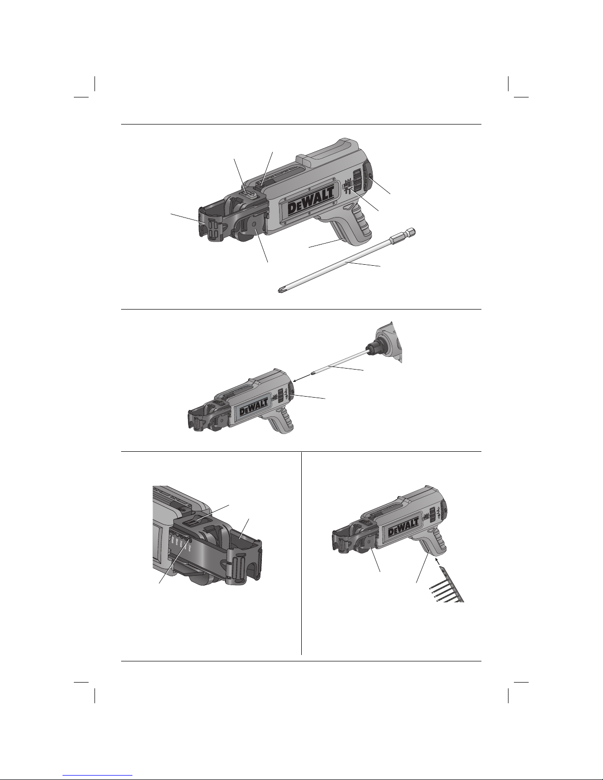
Figure 1
b
e
f
g
c
a
d
Figure 2
g
Figure 3 Figure 4
b
e
h
h
l
d
a
1
Page 4
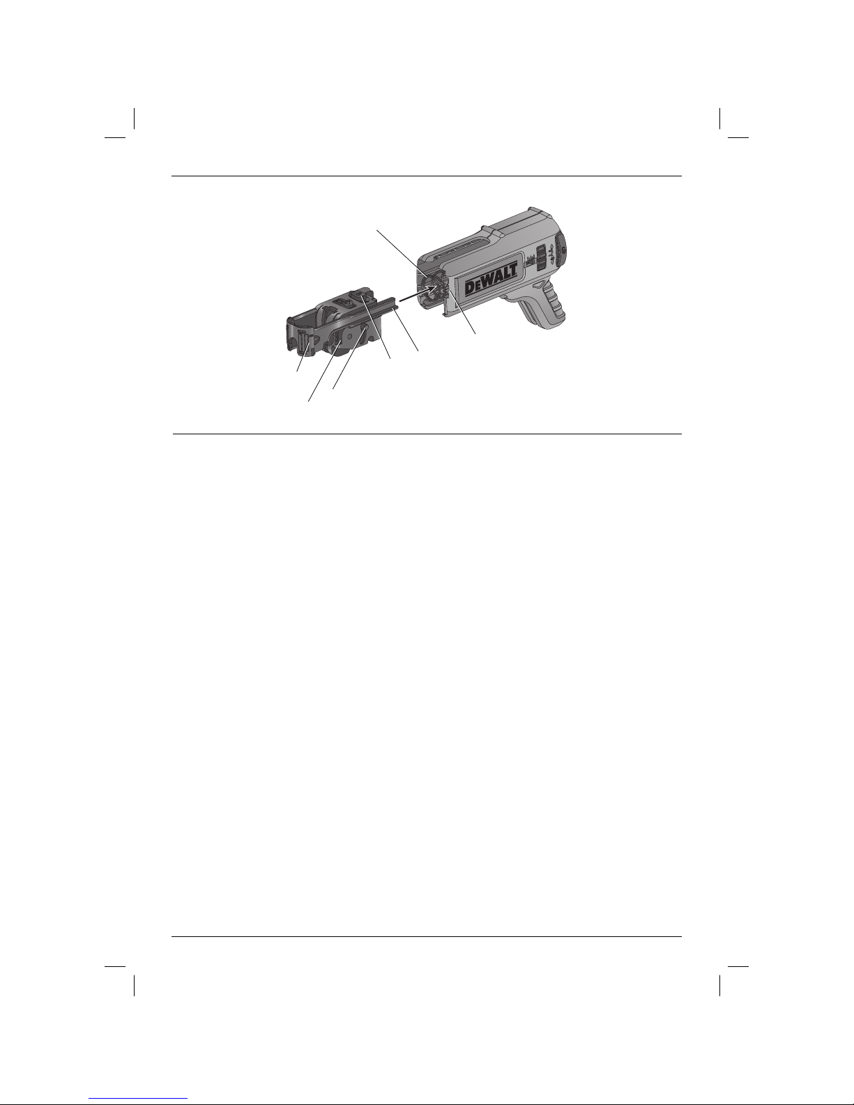
Figure 5
k
j
i
f
e
l
d
2
Page 5

COLLATED MAGAZINE ATTACHMENT
DCF6201
ENGLISH
Congratulations
You have chosen a DEWALT tool. Years of
experience, thorough product development and
innovation make DEWALT one of the most reliable
partners for professional power tool users.
Technical Data
DCF6201
Screw length suitability mm 25 - 57
Weight kg 0.36
Defi nitions: Safety Guidelines
The definitions below describe the level of severity
for each signal word. Please read the manual and
pay attention to these symbols.
DANGER: Indicates an imminently
hazardous situation which, if not avoided,
will result in death or serious injury.
WARNING: Indicates a potentially
hazardous situation which, if not
avoided, could result in death or
serious injury.
CAUTION: Indicates a potentially
hazardous situation which, if not
avoided, may result in minor or
moderate injury.
NOTICE: Indicates a practice not
related to personal injury which, if
not avoided, may result in property
damage.
Denotes risk of electric shock.
Denotes risk of fire.
WARNING: To reduce the risk of injury,
read the instruction manual.
General Power Tool Safety Warnings
WARNING! Read all safety warnings
and all instructions. Failure to follow
the warnings and instructions may result
in electric shock, fire and/or serious
injury.
SAVE ALL WARNINGS AND INSTRUCTIONS
FOR FUTURE REFERENCE
WARNING! Read all safety warnings
and all instructions provided with your
screwdriver (DFC620 or DCF621).
Failure to follow the warnings and
instructions may result in electric shock,
fire and/ or serious injury.
Additional Specifi c Safety Rules for
Collated Magazine Attachment
• The collated magazine is to only be used with
the DEWALT DCF620 or DCF621 screwdriver.
• Observe all operating instructions and safety
regulations contained in the manual for the
screwdriver the magazine accessory is used
with.
• Before use, ensure that the magazine accessory
is properly attached to the tool.
• Avoid body contact with earthed or grounded
surfaces such as pipes, radiators, ranges
and refrigerators. There is an increased risk
of electric shock if your body is earthed or
grounded.
• Disconnect the plug from the power source
and/or the battery pack from the power tool
before making any adjustments, changing
accessories, or storing power tools. Such
preventive safety measures reduce the risk of
starting the power tool accidentally.
• When driving screws, never reach into the
magazine accessory. Keep hands clear of the
advancing mechanism and the spot where the
screw is being driven.
• Do not use the magazine accessory as a
gripping surface.
• Hold power tool by insulated gripping surfaces,
when performing an operation where the
fastener may contact hidden wiring. Fasteners
contacting a “live” wire may make exposed
metal parts of the power tool “live” and could
give the operator an electric shock.
• Use only screw strips that are suitable to this
magazine. Only insert screw strips when the
screwdriver power is off and the trigger is
locked.
3
Page 6

ENGLISH
Residual Risks
In spite of the application of the relevant safety
regulations and the implementation of safety
devices, certain residual risks cannot be avoided.
These are:
– Impairment of hearing.
– Risk of personal injury due to flying particles.
– Risk of burns due to accessories becoming hot
during operation.
– Risk of personal injury due to prolonged use.
Markings on Tool
The following pictograms are shown on the tool:
Read instruction manual before use.
Wear ear protection.
Wear eye protection.
DATE CODE POSITION
The date code, which also includes the year of
manufacture, is printed into the housing.
Example:
2015 XX XX
Year of Manufacture
Package Contents
The package contains:
1 Collated magazine attachment
1 PR2 collated screwdriver bit (DT7205-QZ)
1 Instruction manual
• Check for damage to the attachment, parts or
accessories which may have occurred
during transport.
• Take the time to thoroughly read and
understand this manual prior to operation.
Description (fi g. 1)
WARNING: Never modify the
attachment or any part of it. Damage or
personal injury could result.
a. Screw guide
b. Screw length adjustment
c. Fine depth adjustment
d. Advancing mechanism
e. Shoe
f. Advancing mechanism removal button
g. Release buttons
h. Collated screwdriver bit
INTENDED USE
This collated drywall magazine is a professional
attachment designed to be used with the DCF620
or DCF621 DEWALT screwdriver for professional
driving of collated screws.
DO NOT use under wet conditions or in the
presence of flammable liquids or gases.
DO NOT let children come into contact with the
tool. Supervision is required when inexperienced
operators use this tool.
• Young children and the infirm. This appliance
is not intended for use by young children or
infirm persons without supervision.
• This product is not intended for use by persons
(including children) suffering from diminished
physical, sensory or mental abilities; lack of
experience, knowledge or skills unless they are
supervised by a person responsible for their
safety. Children should never be left alone with
this product.
ASSEMBLY AND ADJUSTMENTS
WARNING: Prior to assembly and
adjustment, always remove the battery
pack. Always switch off the tool before
inserting or removing the battery pack.
WARNING: Use only DEWALT battery
packs and chargers.
Fitting the Collated Screwdriver Bit
(fi g. 1 & 2)
NOTICE: For proper operation only use
a DEWALT collated screwdriver bit.
1. Remove the nose cone from the screwdriver.
2. Remove the mounted bit and bit holder from
the screw driver.
NOTE: Refer to and follow all instructions on
changing bits and holders in your screw driver
manual.
3. Insert the provided collated screwdriving bit (h)
into the bit holder until it clicks into place.
4
Page 7

ENGLISH
Installing and Removing the
Magazine from the Screwdriver
(fi g.2)
With the the nose cone removed and provided driver
bit (h) installed, push the magazine over the bit onto
the screw driver until the magazine clicks into place
and ensure that it does not disengage.
NOTE: If necessary - rotate the attachment to locate
properly on mount.
NOTE: Make sure the screw driver control lever is
set to forward rotation before use.
To remove the magazine, press and hold the release
buttons (g) on both sides of the accessory and pull
accessory off the screwdriver.
OPERATION
Instructions for Use
WARNING: Always observe the safety
instructions and applicable regulations.
WARNING: To reduce the risk of
serious personal injury, turn tool
off and disconnect battery pack
before making any adjustments or
removing/installing attachments or
accessories. An accidental start-up
can cause injury.
Setting Magazine Screw Length
(fi g.3)
This magazine is designed for 25– 57mm (1"– 2¼")
screw lengths. Failure to set the correct screw
length can cause screws to not be driven accurately
which can result in the failure to advance to the next
screw or screws not being driven properly. The shoe
has marked specific slots (l) for each of the most
common screws, however this attachment can still
drive any size screw between 25– 57mm (1"– 2¼").
To accommodate for less common screws adjust to
the next longest slot.
CAUTION: Do not adjust while a screw
strip is in the magazine.
1. Slide screw length adjustment tab(b) to the left.
2. Holding the screw length adjustment tab in
place, adjust the shoe(e) to the desired length.
3. Release the screw length adjustment tab. Make
sure that the locking pin has fully returned and
is in the correct position.
Inserting Collated Screw Strips
(fi g.4)
NOTICE: Use only screw strips that are
suitable to this magazine. Only insert
screw strips when the screwdriver
power is off and the trigger is locked.
Proper use of collated strips will reduce the risk
of injury, reduce jams and prevents screws from
damaging work piece. For best performance use
new, undamaged strips free of debris.
1. Take a collated strip, holding the plastic portion,
and feed from the bottom of the screw guide
(a) and into the bottom of the advancing
mechanism(d).
2. Continue feeding the strip until the first screw is
one slot below the driver bit.
Setting Screw Depth (fi g. 1)
Turn fine depth adjustment (c) anti-clockwise (as
viewed from behind the tool) to make the screw
head stop raised from the work piece.
Turn fine depth adjustment (c) clockwise to make the
screw head stop deeper into the work piece.
There is a window to show where in the adjustment
range the tool is. When the slider is furthest from
the tool the screw head will stop in the most raised
position. When the slider is closest to the screw
driver tool the screw head will stop in its deepest
position.
Driving Screws (fi g. 1)
1. Before driving screws, ensure screwdriver drive
direction is switched to forward position.
NOTE: Always hold the screwdriver
perpendicular to work piece.
2. With the magazine installed on the screwdriver,
position shoe (e) on work piece in location
where screw is to be driven.
3. Switch the screwdriver on by holding the trigger
in the on position. Continue to hold trigger or
engage the trigger lock-on.
4. Apply pressure against work piece. This will
advance screw into alignment with screwdriver
bit.
5. Continue to apply consistent pressure until
screw is driven in completely and screwdriver
clutches disengage.
6. Lift screwdriver from workpiece.
5
Page 8

ENGLISH
The magazine is designed to drive screws
completely into work piece only. Once screwdriver
is lifted, adjustments to screw must be made by first
removing magazine.
Rotating the Collated Attachment
This attachment has the ability to rotate without
being taken off the drywall screwdriver. To rotate,
grip the top portion with one hand, while holding
the drywall screwdriver with the other then rotate. An
audible "click" indicates the magazine is in each of
the available positions.
MAINTENANCE
Your DEWALT power tool has been designed to
operate over a long period of time with a minimum
of maintenance. Continuous satisfactory operation
depends upon proper tool care and regular cleaning.
WARNING: To reduce the risk of
serious personal injury, turn tool
off and disconnect battery pack
before making any adjustments or
removing/installing attachments or
accessories. An accidental start-up
can cause injury.
Lubrication
Your power tool requires no additional lubrication.
Cleaning
WARNING: Blow dirt and dust out of
the main housing with dry air as often
as dirt is seen collecting in and around
the air vents and housing tracks. Wear
approved eye protection and approved
dust mask when performing this
procedure.
WARNING: Never use solvents or
other harsh chemicals for cleaning the
non-metallic parts of the tool. These
chemicals may weaken the materials
used in these parts. Use a cloth
dampened only with water and mild
soap.
For best performance clean magazine by:
1. Remove advancing mechanism from collated
magazine (see Removing and Installing the
Advancing Mechanism instructions).
2. Remove shoe from advancing mechanism.
3. Remove return spring from magazine.
4. Submerge parts in soapy water for 10 minutes.
5. Remove and thoroughly rinse parts.
6. Allow parts to air dry.
7. Reassemble and continue use.
REMOVING AND INSTALLING THE ADVANCING
MECHANISM (FIG. 5)
To remove advancing mechanism:
1. Remove collated magazine attachment from
2. Slightly depress advancing mechanism (d) by
3. Keeping pressure on the shoe (e) with the other
4. Slowly release pressure from the shoe (e) until
To install advancing mechanism:
1. With the collated magazine attachment
2. Push in slightly, then align the spring (k) with the
3. Push advancing mechanism in until you hear
NOTE: The lever arm (l) should be in the up
4. Cycle the advancing mechanism several times
CAUTION: The advancing mechanism
is spring loaded. Two hands must
be used to remove the advancing
mechanism. The spring may eject from
the mechanism.
screwdriver.
pushing on the shoe (e) with one hand.
hand depress advancing mechanism removal
button (f).
the advancing mechanism is out of the collated
magazine.
removed from screwdriver, align the tabs (i)
on the shoe with the slots (j) in the collated
housing.
pocket in the advancing mechanism.
the “click” of the shoe removal button (f).
position (as shown in figure 5) before the
advancing mechanism is installed. If in the down
position, the advancing mechanism will be
locked in place.
by hand to ensure proper function before
installing it onto your screwdriver for use.
6
Page 9

Optional Accessories
WARNING: Since accessories, other
Consult your dealer for further information on the
appropriate accessories.
PR2 Extended Bit x 1 - DT7205-QZ
PR2 Extended Bit x 5 - DT7206-QZ
PR2 Extended Bit x 20 - DT7207-QZ
than those offered by DEWALT, have
not been tested with this product, use
of such accessories with this tool could
be hazardous. To reduce the risk of
injury, only D
accessories should be used with this
product.
EWALT recommended
Protecting the Environment
Separate collection. This product must
not be disposed of with normal
household waste.
Should you find one day that your DEWALT product
needs replacement, or if it is of no further use to you,
do not dispose of it with household waste. Make this
product available for separate collection.
Separate collection of used products
and packaging allows materials to be
recycled and used again. Re-use of
recycled materials helps prevent
environmental pollution and reduces
the demand for raw materials.
Local regulations may provide for separate collection
of electrical products from the household, at
municipal waste sites or by the retailer when you
purchase a new product.
DEWALT provides a facility for the collection and
recycling of DEWALT products once they have
reached the end of their working life. To take
advantage of this service please return your product
to any authorised repair agent who will collect them
on our behalf.
You can check the location of your nearest
authorised repair agent by contacting your local
DEWALT office at the address indicated in this
manual. Alternatively, a list of authorised DEWALT
repair agents and full details of our after-sales
service and contacts are available on the Internet at:
www.2helpU.com.
ENGLISH
7
Page 10

8
Page 11

9
Page 12

Belgique et
Luxembourg België
en Luxemburg
Danmark D
Deutschland D
Ελλάς D
España D
France D
Schweiz
Suisse
Svizzera
Ireland D
Italia D
Nederlands D
Norge D
Österreich D
Portugal D
Suomi D
Sverige D
Türkiye
United
Kingdom
Australia D
Middle East Africa D
DEWALT - Belgium BVBA
Egide Walschaertsstraat 16
2800 Mechelen
EWALT
Roskildevej 22
2620 Albertslund
EWALT
Richard Klinger Str. 11
65510 Idstein
EWALT (Ελλάς) Α.Ε.
EΔΡΑ-ΓΡΑΦΕΙΑ : Στράβωνος 7
& Λ. Βουλιαγμένης, Γλυφάδα 166 74, Αθήνα
SERVICE : Ημερος Τόπος 2 (Χάνι Αδάμ) –
193 00 Ασπρόπυργος
EWALT Ibérica, S.C.A.
Parc de Negocios “Mas Blau”
Edificio Muntadas, c/Bergadá, 1, Of. A6
08820 El Prat de Llobregat (Barcelona)
EWALT
5, allée des Hêtres
BP 30084, 69579 Limonest Cedex
D
EWALT
In der Luberzen 42
8902 Urdorf
EWALT
Calpe House Rock Hill
Black Rock, Co. Dublin
EWALT
via Energypark
20871 Vimercate (MB), IT
EWALT Netherlands BV
Holtum Noordweg 35
6121 RE BORN, Postbus 83, 6120 AB BORN
EWALT
Postboks 4613, Nydalen
0405 Oslo
EWALT
Werkzeug Vertriebsges m.b.H
Oberlaaerstrasse 248, A-1230 Wien
EWALT Limited, SARL
Centro de Escritórios de Sintra Avenida
Almirante Gago Coutinho, 132/134, Edifício 14
2710-418 Sintra
EWALT
PL 47
00521 Helsinki
EWALT
Box 94
431 22 Mölndal
KALE Hırdavat ve Makina A.Ş.
Defterdar Mah. Savaklar Cad. No:15
Edirnekapı / Eyüp / İSTANBUL 34050
TÜRKİYE
D
EWALT, 210 Bath Road;
Slough, Berks SL1 3YD
EWALT
82 Taryn Drive, Epping
VIC 3076 Australia
EWALT
P.O. Box - 17164,
Jebel Ali Free Zone (South), Dubai, UAE
Tel: NL 32 15 47 37 63
Tel: FR 32 15 47 37 64
Fax: 32 15 47 37 99
Tel: 70 20 15 10
Fax: 70 22 49 10
Tel: 06126-21-1
Fax: 06126-21-2770
Τηλ : 00302108981616
Φαξ: 00302108983570
Tel: 934 797 400
Fax: 934 797 419
Tel: 04 72 20 39 20
Fax: 04 72 20 39 00
Tel: 044 - 755 60 70
Fax: 044 - 730 70 67
Tel: 00353-2781800
Fax: 00353-2781811
Tel: 800-014353
39 039 9590200
Fax: 39 039 9590313
Tel: 31 164 283 063
Fax: 31 164 283 200
Tel: 45 25 13 00
Fax: 45 25 08 00
Tel: 01 - 66116 - 0
Fax: 01 - 66116 - 614
Tel: 214 66 75 00
Fax: 214 66 75 80
Puh: 010 400 4333
Faksi: 0800 411 340
Tel: 031 68 61 60
Fax: 031 68 60 08
Tel: 0212 533 52 55
Faks: 0212 533 10 05
Tel: 01753-567055
Fax: 01753-572112
Tel: Aust 1800 338 002
Tel: NZ 0800 339 258
Tel: 971 4 812 7400
Fax: 971 4 2822765
www.dewalt.be
enduser.BE@SBDinc.com
www.dewalt.dk
kundeservice.dk@sbdinc.com
www.dewalt.de
infodwge@sbdinc.com
www.dewalt.gr
Greece.Service@sbdinc.com
www.dewalt.es
respuesta.postventa@sbdinc.com
www.dewalt.fr
scufr@sbdinc.com
www.dewalt.ch
service@rofoag.ch
www.dewalt.ie
www.dewalt.it
www.dewalt.nl
www.dewalt.no
kundeservice.no@sbdinc.com
www.dewalt.at
service.austria@sbdinc.com
www.dewalt.pt
resposta.posvenda@sbdinc.com
www.dewalt.fi
asiakaspalvelu.fi@sbdinc.com
www.dewalt.se
kundservice.se@sbdinc.com
www.dewalt.com.tr
www.dewalt.co.uk
emeaservice@sbdinc.com
www.dewalt.com.au
www.dewalt.co.nz
www.dewalt.ae
Service.MEA@sbdinc.com
N433179 03/15
 Loading...