

Page 1

DCD991
DCD996
Final page size: A5 (148mm x 210mm)
Page 2

B
Copyright
DeWALT
English (original instructions) 3
Page 3
1
Fig. A
Fig. B
DCD996
13
15
14
16
9
3
1
2
10
18
12
11
8
9
7
6
5
4
8
9
17
8
Page 4
2
Fig. F
Fig. D Fig. E
Fig. G Fig. H
Fig. I
Fig. C
5 5
66
4
7
18
Page 5

ENGLISH
3
DCD991 DCD996
Screwdriving
Vibration emission value ah = m/s
2
<2.5 <2.5
Uncertainty K = m/s
2
1.5 1.5
The vibration emission level given in this information sheet has
been measured in accordance with a standardised test given in
EN60745 and may be used to compare one tool with another. It
may be used for a preliminary assessment ofexposure.
WARNING: The declared vibration emission level
represents the main applications of the tool. However if
the tool is used for different applications, with different
accessories or poorly maintained, the vibration emission
may differ. This may significantly increase the exposure
level over the total workingperiod.
An estimation of the level of exposure to vibration should
also take into account the times when the tool is switched
off or when it is running but not actually doing the job.
This may significantly reduce the exposure level over the
total workingperiod.
Identify additional safety measures to protect the operator
from the effects of vibration such as: maintain the tool
and the accessories, keep the hands warm, organisation
of workpatterns.
Battery pack DCB181 DCB182
Battery type Li-Ion Li-Ion
Voltage V
DC
18 18
Capacity Ah 1.5 4.0
Weight kg 0.35 0.61
Battery pack DCB183/B DCB184/B DCB185
Battery type Li-Ion Li-Ion Li-Ion
Voltage V
DC
18 18 18
Capacity Ah 2.0 5.0 1.3
Weight kg 0.40/0.45 0.62/0.67 0.35
Battery pack DCB546
Battery type Li-Ion
Voltage V
DC
18/54
Capacity Ah 6.0/2.0
Weight kg 1.05
Congratulations!
You have chosen a
DeWALT
tool. Years of experience, thorough
product development and innovation make
DeWALT
one of the
most reliable partners for professional power toolusers.
Technical Data
DCD991 DCD996
Voltage V
DC
18 18
Type 1/10 1/10
Battery type Li-Ion Li-Ion
Power output W 820 820
No load speed Drill, Driver/Hammer
1st gear min-10–450 0–450/500
2nd gear 0–1300 0–1300/1500
3rd gear 0–2000 0–2000/2250
Impact rate
1st gear min
-1
– 0–8600
2nd gear – 0–25500
3rd gear – 0–38250
Max. torque (hard/soft)
hard Nm 95 95
soft Nm 66 66
Chuck capacity mm 1.5–13 1.5–13
Maximum drilling capcity
Wood mm 55 55
Metal 15 15
Masonry – 13
Weight (without battery pack) kg 1.5 1.6
Noise values and vibration values (triax vector sum) according to EN60745:
LPA (emission sound pressure
level)
dB(A) 75 97
LWA (sound power level) dB(A) 86 108
K (uncertainty for the given
sound level)
dB(A) 3 3
Drilling into metal
Vibration emission value a
h,D
= m/s
2
<2.5 <2.5
Uncertainty K = m/s
2
1.5 1.5
Impact drilling
Vibration emission value a
h,ID
= m/s
2
– 15.0
Uncertainty K = m/s
2
– 3.9
BRUSHLESS CORDLESS 13 mm DRILL/DRIVER,
DCD991
BRUSHLESS CORDLESS 13 mm DRILL/DRIVER/
HAMMERDRILL, DCD996
Page 6

4
ENGLISH
Charger DCB107
Mains voltage V
AC
230
Battery type 10.8/14.4/18 Li-Ion
Approx. charging time of
battery packs
min 60 (1.3 Ah) 70 (1.5 Ah) 90 (2.0 Ah)
140 (3.0 Ah) 185 (4.0 Ah) 240 (5.0 Ah)
Weight kg 0.29
Charger DCB112
Mains voltage V
AC
230
Battery type 10.8/14.4/18 Li-Ion
Approx. charging time of
battery packs
min 40 (1.3 Ah) 45 (1.5 Ah) 60 (2.0 Ah)
90 (3.0 Ah) 120 (4.0 Ah) 150 (5.0 Ah)
Weight kg 0.36
Charger DCB113
Mains voltage V
AC
230
Battery type 10.8/14.4/18 Li-Ion
Approx. charging time of
battery packs
min 30 (1.3 Ah) 35 (1.5 Ah) 50 (2.0 Ah)
70 (3.0 Ah) 100 (4.0 Ah) 120 (5.0 Ah)
Weight kg 0.4
Charger DCB115
Mains voltage V
AC
230
Battery type 10.8/14.4/18 Li-Ion
Approx. charging time of
battery packs
min 22 (1.3 Ah) 22 (1.5 Ah) 30 (2.0 Ah)
45 (3.0 Ah) 60 (4.0 Ah) 75 (5.0 Ah)
Weight kg 0.5
Charger DCB118
Mains voltage V
AC
230
Battery type 18/54 Li-Ion
Approx. charging time of
battery packs
min 22 (1.3 Ah) 22 (1.5 Ah) 30 (2.0 Ah)
45 (3.0 Ah) 60 (4.0 Ah) 75 (5.0 Ah)
60 (6.0 Ah)
Weight kg 0,66
The DCB107, DCB112, DCB113 and DCB115 chargers accept
10.8V, 14.4V, 18V Li-Ion XR and XRFLEXVOLTTM battery packs
(DCB123, DCB127, DCB141, DCB142, DCB143, DCB144, DCB145,
DCB181, DCB182, DCB183, DCB183B, DCB184, DCB184B,
DCB185 and DCB546) batterypacks.
The DCB118 charger accepts 18V Li-Ion XR and XRFLEXVOLTTM
battery packs (DCB181, DCB182, DCB183, DCB183B, DCB184,
DCB184B, DCB185 and DCB546).
Fuses:
Europe 230V tools 10 Amperes. mains
U.K. & Ireland 230V tools 3 Amperes. in plugs
EC-Declaration of Conformity
Machinery Directive
Drill/Driver/Hammerdrill
DCD991, DCD996
DeWALT
declares that these products described under
Technical Data are in compliance with:
2006/42/EC, EN60745-1:2009+A11:2010, EN60745-2-1:2010,
EN60745-2-2:2010.
These products also comply with Directive 2014/30/EU and
2011/65/EU. For more information, please contact
DeWALT
at
the following address or refer to the back of themanual.
The undersigned is responsible for compilation of the technical
file and makes this declaration on behalf of
DeWALT
.
Markus Rompel
Director Engineering
DeWALT
, Richard-Klinger-Straße 11,
D-65510, Idstein, Germany
29.02.2016
WARNING: To reduce the risk of injury, read the
instruction manual.
Definitions: Safety Guidelines
The definitions below describe the level of severity for each
signal word. Please read the manual and pay attention to
thesesymbols.
DANGER: Indicates an imminently hazardous
situation which, if not avoided, will result in death or
seriousinjury.
WARNING: Indicates a potentially hazardous situation
which, if not avoided, could result in death or
seriousinjury.
CAUTION: Indicates a potentially hazardous situation
which, if not avoided, may result in minor or
moderateinjury.
NOTICE: Indicates a practice not related to
personal injury which, if not avoided, may result in
propertydamage.
Denotes risk of electricshock.
Denotes risk offire.
General Power Tool Safety Warnings
WARNING: Read all safety warnings and all
instructions. Failure to follow the warnings and
instructions may result in electric shock, fire and/or
seriousinjury.
Page 7

5
ENGLISH
SAVE ALL WARNINGS AND INSTRUCTIONS
FOR FUTURE REFERENCE
The term “power tool” in the warnings refers to your mainsoperated (corded) power tool or battery-operated (cordless)
powertool.
1) Work area safety
a ) Keep work area clean and well lit. Cluttered or dark
areas inviteaccidents.
b ) Do not operate power tools in explosive
atmospheres, such as in the presence of flammable
liquids, gases or dust. Power tools create sparks which
may ignite the dust orfumes.
c ) Keep children and bystanders away while operating
a power tool. Distractions can cause you to losecontrol.
2) Electrical safety
a ) Power tool plugs must match the outlet. Never
modify the plug in any way. Do not use any adapter
plugs with earthed (grounded) power tools.
Unmodified plugs and matching outlets will reduce risk of
electricshock.
b ) Avoid body contact with earthed or grounded
surfaces such as pipes, radiators, ranges and
refrigerators. There is an increased risk of electric shock if
your body is earthed orgrounded.
c ) Do not expose power tools to rain or wet conditions.
Water entering a power tool will increase the risk of
electricshock.
d ) Do not abuse the cord. Never use the cord for
carrying, pulling or unplugging the power tool. Keep
cord away from heat, oil, sharp edges or moving
parts. Damaged or entangled cords increase the risk of
electricshock.
e ) When operating a power tool outdoors, use an
extension cord suitable for outdoor use. Use of a cord
suitable for outdoor use reduces the risk of electricshock.
f ) If operating a power tool in a damp location is
unavoidable, use a residual current device (RCD)
protected supply. Use of an RCD reduces the risk of
electricshock.
3) Personal safety
a ) Stay alert, watch what you are doing and use
common sense when operating a power tool. Do not
use a power tool while you are tired or under the
influence of drugs, alcohol or medication. A moment
of inattention while operating power tools may result in
serious personalinjury.
b ) Use personal protective equipment. Always wear
eye protection. Protective equipment such as dust mask,
non-skid safety shoes, hard hat, or hearing protection used
for appropriate conditions will reduce personalinjuries.
c ) Prevent unintentional starting. Ensure the switch
is in the off position before connecting to power
source and/or battery pack, picking up or carrying
the tool. Carrying power tools with your finger on the
switch or energising power tools that have the switch on
invitesaccidents.
d ) Remove any adjusting key or wrench before turning
the power tool on. A wrench or a key left attached
to a rotating part of the power tool may result in
personalinjury.
e ) Do not overreach. Keep proper footing and balance
at all times. This enables better control of the power tool
in unexpectedsituations.
f ) Dress properly. Do not wear loose clothing or
jewellery. Keep your hair, clothing and gloves away
from moving parts. Loose clothes, jewellery or long hair
can be caught in movingparts.
g ) If devices are provided for the connection of dust
extraction and collection facilities, ensure these are
connected and properly used. Use of dust collection
can reduce dust-relatedhazards.
4) Power tool use and care
a ) Do not force the power tool. Use the correct power
tool for your application. The correct power tool
will do the job better and safer at the rate for which it
wasdesigned.
b ) Do not use the power tool if the switch does not turn
it on and off. Any power tool that cannot be controlled
with the switch is dangerous and must berepaired.
c ) Disconnect the plug from the power source and/or
the battery pack from the power tool before making
any adjustments, changing accessories, or storing
power tools. Such preventive safety measures reduce the
risk of starting the power toolaccidentally.
d ) Store idle power tools out of the reach of children
and do not allow persons unfamiliar with the power
tool or these instructions to operate the power tool.
Power tools are dangerous in the hands of untrainedusers.
e ) Maintain power tools. Check for misalignment or
binding of moving parts, breakage of parts and any
other condition that may affect the power tool’s
operation. If damaged, have the power tool repaired
before use. Many accidents are caused by poorly
maintained powertools.
f ) Keep cutting tools sharp and clean. Properly
maintained cutting tools with sharp cutting edges are less
likely to bind and are easier tocontrol.
g ) Use the power tool, accessories and tool bits etc.,
in accordance with these instructions taking into
account the working conditions and the work to be
performed. Use of the power tool for operations different
from those intended could result in a hazardoussituation.
5) Battery tool use and care
a ) Recharge only with the charger specified by the
manufacturer. A charger that is suitable for one type
of battery pack may create a risk of fire when used with
another batterypack.
Page 8

6
ENGLISH
b ) Use power tools only with specifically designated
battery packs. Use of any other battery packs may create
a risk of injury andfire.
c ) When battery pack is not in use, keep it away from
other metal objects like paper clips, coins, keys,
nails, screws or other small metal objects that can
make a connection from one terminal to another.
Shorting the battery terminals together may cause burns
or afire.
d ) Under abusive conditions, liquid may be ejected
from the battery; avoid contact. If contact
accidentally occurs, flush with water. If liquid
contacts eyes, additionally seek medical help. Liquid
ejected from the battery may cause irritation orburns.
6) Service
a ) Have your power tool serviced by a qualified repair
person using only identical replacement parts. This
will ensure that the safety of the power tool ismaintained.
Additional Specific Safety Rules for Drills/
Drivers/Hammerdrills
• Wear ear protectors when impact drilling. Exposure to
noise can cause hearing loss.
• Use auxiliary handles, if supplied with the tool. Loss of
control can cause personal injury.
• Hold power tool by insulated gripping surfaces when
performing an operation where the cutting tool or the
fastener may contact hidden wiring. Cutting accessory or
fasteners contacting a “live” wire may make exposed metal
parts of the power tool “live” and could give the operator an
electric shock.
• Use clamps or other practical way to secure and support
the workpiece to a stable platform. Holding the work by
hand or against your body is unstable and may lead to loss
of control.
• Wear ear protectors when hammering for extended
periods of time. Prolonged exposure to high intensity noise
can cause hearing loss. Temporary hearing loss or serious ear
drum damage may result from high sound levels generated by
hammerdrilling.
• Wear safety goggles or other eye protection. Hammering
and drilling operations cause chips to fly. Flying particles can
cause permanent eye damage.
• Hammer bits and tools get hot during operation. Wear
gloves when touching them.
Residual Risks
The following risks are inherent to the use of percussion drills:
• Injuries caused by touching the rotating parts or hot parts of
the tool.
In spite of the application of the relevant safety regulations
and the implementation of safety devices, certain residual risks
cannot be avoided. These are:
• Impairment of hearing.
• Risk of squeezing fingers when changing accessories.
• Health hazards caused by breathing dust developed when
working in wood.
• Risk of personal injury due to flying particles.
• Risk of personal injury due to prolonged use.
Electrical Safety
The electric motor has been designed for one voltage only.
Always check that the battery pack voltage corresponds to the
voltage on the rating plate. Also make sure that the voltage of
your charger corresponds to that of yourmains.
Your
DeWALT
charger is double insulated in
accordance with EN60335; therefore no earth wire
isrequired.
If the supply cord is damaged, it must be replaced by a
specially prepared cord available through the
DeWALT
serviceorganisation.
Mains Plug Replacement
(U.K. & Ireland Only)
If a new mains plug needs to be fitted:
• Safely dispose of the oldplug.
• Connect the brown lead to the live terminal in theplug.
• Connect the blue lead to the neutralterminal.
WARNING: No connection is to be made to the
earthterminal.
Follow the fitting instructions supplied with good quality plugs.
Recommended fuse: 3A.
Using an Extension Cable
An extension cord should not be used unless absolutely
necessary. Use an approved extension cable suitable for
the power input of your charger (see Technical Data). The
minimum conductor size is 1mm2; the maximum length
is30m.
When using a cable reel, always unwind the cablecompletely.
SAVE THESE INSTRUCTIONS
Chargers
DeWALT
chargers require no adjustment and are designed to be
as easy as possible tooperate.
Important Safety Instructions for All
Battery Chargers
SAVE THESE INSTRUCTIONS: This manual contains important
safety and operating instructions for compatible battery
chargers (refer to TechnicalData).
• Before using charger, read all instructions and cautionary
markings on charger, battery pack, and product using
batterypack.
WARNING: Shock hazard. Do not allow any liquid to get
inside charger. Electric shock mayresult.
WARNING: We recommend the use of a residual current
device with a residual current rating of 30mA orless.
CAUTION: Burn hazard. To reduce the risk of injury,
charge only
DeWALT
rechargeable batteries. Other types of
batteries may burst causing personal injury anddamage.
Page 9

7
ENGLISH
CAUTION: Children should be supervised to ensure that
they do not play with theappliance.
NOTICE: Under certain conditions, with the charger
plugged into the power supply, the exposed charging
contacts inside the charger can be shorted by foreign
material. Foreign materials of a conductive nature such
as, but not limited to, steel wool, aluminum foil or any
buildup of metallic particles should be kept away from
charger cavities. Always unplug the charger from the
power supply when there is no battery pack in the cavity.
Unplug charger before attempting to clean
• DO NOT attempt to charge the battery pack with any
chargers other than the ones in this manual. The charger
and battery pack are specifically designed to worktogether.
• These chargers are not intended for any uses other than
charging
DeWALT
rechargeable batteries. Any other uses
may result in risk of fire, electric shock orelectrocution.
• Do not expose charger to rain orsnow.
• Pull by plug rather than cord when disconnecting
charger. This will reduce risk ofdamage to electric plug
andcord.
• Make sure that cord is located so that it will not be
stepped on, tripped over, or otherwise subjected to
damage orstress.
• Do not use an extension cord unless it is absolutely
necessary. Use of improper extension cord could result in risk
of fire,electric shock, orelectrocution.
• Do not place any object on top of charger or place
the charger on a soft surface that might block the
ventilation slots and result in excessive internal heat.
Place the charger in a position away from any heat source. The
charger is ventilated through slots in the top and the bottom
of thehousing.
• Do not operate charger with damaged cord or plug—
have them replacedimmediately.
• Do not operate charger if it has received a sharp blow,
been dropped, or otherwise damaged in any way. Take it
to an authorised servicecentre.
• Do not disassemble charger; take it to an authorised
service centre when service or repair is required. Incorrect
reassembly may result in a risk of electric shock, electrocution
orfire.
• In case of damaged power supply cord the supply cord must
be replaced immediately by the manufacturer, its service agent
or similar qualified person to prevent anyhazard.
• Disconnect the charger from the outlet before
attempting any cleaning. This will reduce the risk of
electric shock. Removing the battery pack will not reduce
thisrisk.
• NEVER attempt to connect two chargerstogether.
• The charger is designed to operate on standard
230V household electrical power. Do not attempt to
use it on any other voltage. This does not apply to the
vehicularcharger.
Charging a Battery (Fig. B)
1. Plug the charger into an appropriate outlet before inserting
battery pack.
2. Insert the battery pack
8
into the charger, making sure the
battery pack is fully seated in the charger. The red (charging)
light will blink repeatedly indicating that the charging
process has started.
3. The completion of charge will be indicated by the red
light remaining ON continuously. The battery pack is fully
charged and may be used at this time or left in the charger.
To remove the battery pack from the charger, push the
battery release button
9
on the battery pack.
NOTE: To ensure maximum performance and life of lithium-ion
battery packs, charge the battery pack fully before first use.
Charger Operation
Refer to the indicators below for the charge status of the battery
pack.
Charge Indicators
Charging
Fully Charged
Hot/Cold Pack Delay*
* The red light will continue to blink, but a yellow indicator light
will be illuminated during this operation. Once the battery pack
has reached an appropriate temperature, the yellow light will
turn off and the charger will resume the charging procedure.
The compatible charger(s) will not charge a faulty battery pack.
The charger will indicate faulty battery by refusing to light or by
displaying problem pack or charger blink pattern.
NOTE: This could also mean a problem with a charger.
If the charger indicates a problem, take the charger and battery
pack to be tested at an authorised service centre.
Hot/Cold Pack Delay
When the charger detects a battery pack that is too hot or too
cold, it automatically starts a Hot/Cold Pack Delay, suspending
charging until the battery pack has reached an appropriate
temperature. The charger then automatically switches to the
pack charging mode. This feature ensures maximum battery
pack life.
A cold battery pack will charge at a slower rate than a warm
battery pack. The battery pack will charge at that slower rate
throughout the entire charging cycle and will not return to
maximum charge rate even if the battery pack warms.
The DCB118 charger is equipped with an internal fan designed
to cool the battery pack. The fan will turn on automatically
when the battery pack needs to be cooled. Never operate the
charger if the fan does not operate properly or if ventilation slots
are blocked. Do not permit foreign objects to enter the interior
of the charger.
Page 10

8
ENGLISH
Electronic Protection System
XR Li-Ion tools are designed with an Electronic Protection
System that will protect the battery pack against overloading,
overheating or deep discharge.
The tool will automatically turn off if the Electronic Protection
System engages. If this occurs, place the lithium-ion battery
pack on the charger until it is fully charged.
Wall Mounting
These chargers are designed to be wall mountable or to sit
upright on a table or work surface. If wall mounting, locate the
charger within reach of an electrical outlet, and away from a
corner or other obstructions which may impede air flow. Use
the back of the charger as a template for the location of the
mounting screws on the wall. Mount the charger securely using
drywall screws (purchased separately) at least 25.4mm long
with a screw head diameter of 7–9mm, screwed into wood to
an optimal depth leaving approximately 5.5mm of the screw
exposed. Align the slots on the back of the charger with the
exposed screws and fully engage them in the slots.
Charger Cleaning Instructions
WARNING: Shock hazard. Disconnect the charger
from the AC outlet before cleaning. Dirt and grease
may be removed from the exterior of the charger using a
cloth or soft non-metallic brush. Do not use water or any
cleaning solutions. Never let any liquid get inside the tool;
never immerse any part of the tool into a liquid.
Battery Packs
Important Safety Instructions for All
Battery Packs
When ordering replacement battery packs, be sure to include
catalog number and voltage.
The battery pack is not fully charged out of the carton. Before
using the battery pack and charger, read the safety instructions
below. Then follow charging procedures outlined.
READ ALL INSTRUCTIONS
• Do not charge or use battery in explosive atmospheres,
such as in the presence of flammable liquids, gases or
dust. Inserting or removing the battery from the charger may
ignite the dust or fumes.
• Never force battery pack into charger. Do not modify
battery pack in any way to fit into a non-compatible
charger as battery pack may rupture causing serious
personal injury.
• Charge the battery packs only in
DeWALT
chargers.
• DO NOT splash or immerse in water or other liquids.
• Do not store or use the tool and battery pack in
locations where the temperature may reach or exceed
40 ˚C (104 ˚F) (such as outside sheds or metal buildings
in summer).
• Do not incinerate the battery pack even if it is severely
damaged or is completely worn out. The battery pack can
explode in a fire. Toxic fumes and materials are created when
lithium-ion battery packs are burned.
• If battery contents come into contact with the skin,
immediately wash area with mild soap and water. If
battery liquid gets into the eye, rinse water over the open eye
for 15 minutes or until irritation ceases. If medical attention
is needed, the battery electrolyte is composed of a mixture of
liquid organic carbonates and lithium salts.
• Contents of opened battery cells may cause respiratory
irritation. Provide fresh air. If symptoms persists, seek medical
attention.
WARNING: Burn hazard. Battery liquid may be flammable
if exposed to spark or flame.
WARNING: Never attempt to open the battery pack for
any reason. If battery pack case is cracked or damaged,
do not insert into charger. Do not crush, drop or damage
battery pack. Do not use a battery pack or charger that
has received a sharp blow, been dropped, run over or
damaged in any way (i.e., pierced with a nail, hit with
a hammer, stepped on). Electric shock or electrocution
may result. Damaged battery packs should be returned to
service centre for recycling.
WARNING: Fire hazard. Do not store or carry the
battery pack so that metal objects can contact
exposed battery terminals. For example, do not place
the battery pack in aprons, pockets, tool boxes, product kit
boxes, drawers, etc., with loose nails, screws, keys, etc.
CAUTION: When not in use, place tool on its side on
a stable surface where it will not cause a tripping
or falling hazard. Some tools with large battery packs
will stand upright on the battery pack but may be easily
knocked over.
Transportation
WARNING: Fire hazard. Transporting batteries can
possibly cause fire if the battery terminals inadvertently
come in contact with conductive materials. When
transporting batteries, make sure that the battery
terminals are protected and well insulated from materials
that could contact them and cause a short circuit.
DeWALT
batteries comply with all applicable shipping
regulations as prescribed by industry and legal standards which
include UN Recommendations on the Transport of Dangerous
Goods; International Air Transport Association (IATA) Dangerous
Goods Regulations, International Maritime Dangerous Goods
(IMDG) Regulations, and the European Agreement Concerning
The International Carriage of Dangerous Goods by Road (ADR).
Lithium-ion cells and batteries have been tested to section 38.3
of the UN Recommendations on the Transport of Dangerous
Goods Manual of Tests and Criteria.
In most instances, shipping a
DeWALT
battery pack will be
excepted from being classified as a fully regulated Class 9
Hazardous Material. In general, only shipments containing a
lithium-ion battery with an energy rating greater than 100 Watt
Hours (Wh) will require being shipped as fully regulated Class 9.
All lithium-ion batteries have the Watt Hour rating marked on
the pack. Furthermore, due to regulation complexities,
DeWALT
does not recommend air shipping lithium-ion battery packs
alone regardless of Watt Hour rating. Shipments of tools with
Page 11

9
ENGLISH
batteries (combo kits) can be air shipped as excepted if the Watt
Hour rating of the battery pack is no greater than 100 Whr.
Regardless of whether a shipment is considered excepted
or fully regulated, it is the shipper's responsibility to consult
the latest regulations for packaging, labeling/marking and
documentation requirements.
The information provided in this section of the manual is
provided in good faith and believed to be accurate at the time
the document was created. However, no warranty, expressed or
implied, is given. It is the buyer’s responsibility to ensure that its
activities comply with the applicable regulations.
Transporting the FLEXVOLTTM Battery
The
DeWALT
FLEXVOLTTM battery has two modes: Use and
Transport.
Use Mode: When the FLEXVOLTTM battery stands alone or is in
a
DeWALT
18V product, it will operate as an 18V battery. When
the FLEXVOLTTM battery is in a 54V or a 108V (two 54V batteries)
product, it will operate as a 54V battery.
Transport Mode: When the cap is attached to the FLEXVOLTTM
battery, the battery is in Transport mode. Keep the cap for
shipping.
When in Transport mode, strings
of cells are electrically
disconnected within the pack
resulting in 3 batteries with a
lower Watt hour (Wh) rating as compared to 1 battery with a
higher Watt hour rating. This increased quantity of 3 batteries
with the lower Watt hour rating can exempt the pack from
certain shipping regulations that are imposed upon the higher
Watt hour batteries.
For example, the Transport
Wh rating might indicate
3x36 Wh, meaning 3
batteries of 36 Wh each.
The Use Wh rating might
indicate 108Wh (1battery implied).
Storage Recommendations
1. The best storage place is one that is cool and dry away
from direct sunlight and excess heat or cold. For optimum
battery performance and life, store battery packs at room
temperature when not in use.
2. For long storage, it is recommended to store a fully charged
battery pack in a cool, dry place out of the charger for
optimal results.
NOTE: Battery packs should not be stored completely depleted
of charge. The battery pack will need to be recharged before
use.
Labels on Charger and Battery Pack
In addition to the pictographs used in this manual, the labels
on the charger and the battery pack may show the following
pictographs:
Example of Use and Transport Label Marking
Read instruction manual before use.
See Technical Data for charging time.
Do not probe with conductive objects.
Do not charge damaged battery packs.
Do not expose to water.
Have defective cords replaced immediately.
Charge only between 4 ˚C and 40 ˚C.
Only for indoor use.
Discard the battery pack with due care for the
environment.
Charge
DeWALT
battery packs only with designated
DeWALT
chargers. Charging battery packs other
than the designated
DeWALT
batteries with a
DeWALT
charger may make them burst or lead to
other dangerous situations.
Do not incinerate the battery pack.
USE (without transport cap). Example: Wh rating
indicates 108 Wh (1 battery with 108 Wh).
TRANSPORT (with built-in transport cap). Example:
Wh rating indicates 3 x 36 Wh (3batteries of 36 Wh).
Battery Type
The DCD991 and DCD996 operate on a 18V Li-Ion XR and
XRFLEXVOLTTM battery packs
These battery packs may be used: DCB181, DCB182, DCB183,
DCB183B, DCB184, DCB184B, DCB185, DCB546. Refer to
Technical Data for moreinformation.
Package Contents
The package contains:
1 Brushless cordless drill/driver (DCD991)
1 Brushless cordless hammerdrill (DCD996)
1 Li-Ion battery packs (M1, P1, T1)
2 Li-Ion battery packs (M2, P2, T2)
3 Li-Ion battery packs (M3, P3, T3)
1 Tool Connect™ App instruction manual
Page 12

10
ENGLISH
1 Kitbox
1 Charger
1 Side handle
1 Instruction manual
NOTE: Battery packs, chargers and kitboxes are not included
with N-models. Battery packs and chargers are not included
with NT models. Bmodels include Bluetooth® battery packs.
NOTE: The Bluetooth® word mark and logos are registered
trademarks owned by the Bluetooth®, SIG, Inc. and any use of
such marks by
DeWALT
is under license. Other trademarks and
trade names are those of their respective owners.
• Check for damage to the tool, parts or accessories which may
have occurred duringtransport.
• Take the time to thoroughly read and understand this manual
prior tooperation.
Markings on Tool
The following pictograms are shown on the tool:
Read instruction manual before use.
Date Code Position
The date code, which also includes the year of manufacture, is
printed into thehousing.
Example:
2016 XX XX
Year of Manufacture
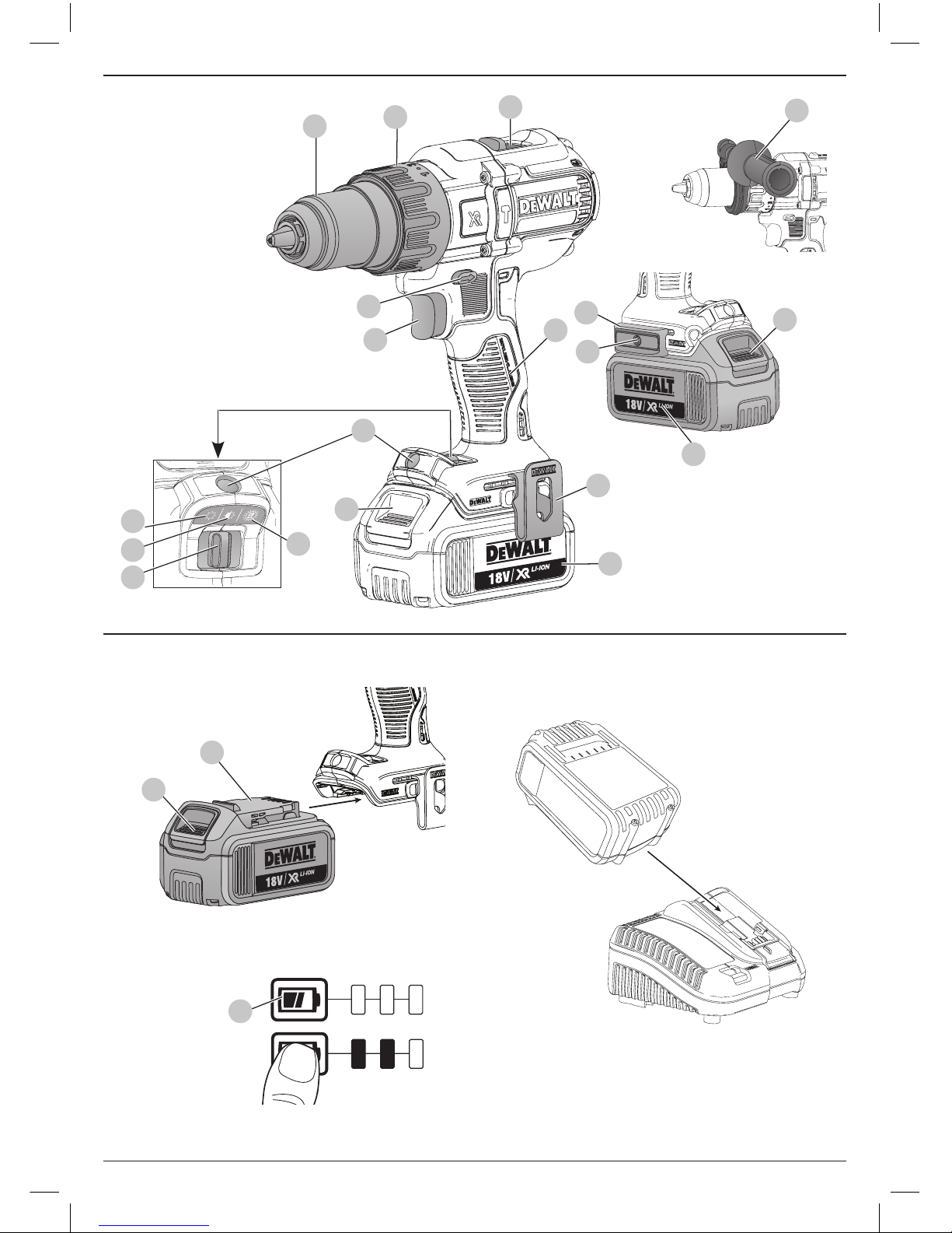
Description (Fig. A, B)
WARNING: Never modify the power tool or any part of it.
Damage or personal injury couldresult.
1
Trigger switch
2
Forward/reverse control button
3
Worklight
4
Chuck
5
Torque adjustment collar
6
Gear shifter
7
Side handle
8
Battery pack
9
Battery release button
10
Belt hook
11
Mounting screw
12
Magnetic bit holder
13
Worklight switch
14
Low worklight mode
15
Medium worklight mode
16
Spotlight mode
17
Fuel gauge
18
Main handle
Intended Use
These drills drivers/hammerdrills are designed for professional
drilling, percussion drilling and screwdriving applications. This
tool is compatible with Bluetooth® Battery Technology and with
the
DeWALT
Tool Connect™ App. Please see your Tool Connect™
App instruction manual for more information.
DO NOT use under wet conditions or in the presence of
flammable liquids orgases.
These drills/drivers/hammerdrills are professional power tools.
DO NOT let children come into contact with the tool.
Supervision is required when inexperienced operators use
thistool.
• Young children and the infirm. This appliance is not
intended for use by young children or infirm persons
without supervision.
• This product is not intended for use by persons (including
children) suffering from diminished physical, sensory or
mental abilities; lack of experience, knowledge or skills
unless they are supervised by a person responsible for their
safety. Children should never be left alone with thisproduct.
ASSEMBLY AND ADJUSTMENTS
WARNING: To reduce the risk of serious personal
injury, turn tool off and disconnect battery pack
before making any adjustments or removing/
installing attachments or accessories. An accidental
start-up can causeinjury.
WARNING: Use only
DeWALT
battery packs andchargers.
Inserting and Removing the Battery Pack
from the Tool (Fig. B)
NOTE: Make sure your battery pack
8
is fullycharged.
To Install the Battery Pack into the Tool
Handle
1. Align the battery pack
8
with the rails inside the tool’s
handle (Fig. B).
2. Slide it into the handle until the battery pack is firmly seated
in the tool and ensure that you hear the lock snap intoplace.
To Remove the Battery Pack from the Tool
1. Press the release button
9
and firmly pull the battery pack
out of the toolhandle.
2. Insert battery pack into the charger as described in the
charger section of thismanual.
Fuel Gauge Battery Packs (Fig. B)
Some
DeWALT
battery packs include a fuel gauge which
consists of three green LED lights that indicate the level of
charge remaining in the batterypack.
To actuate the fuel gauge, press and hold the fuel gauge button
17
. A combination of the three green LED lights will illuminate
designating the level of charge left. When the level of charge
in the battery is below the usable limit, the fuel gauge will not
illuminate and the battery will need to berecharged.
NOTE: The fuel gauge is only an indication of the charge left on
the battery pack. It does not indicate tool functionality and is
subject to variation based on product components, temperature
and end-userapplication.
Page 13

11
ENGLISH
Variable Speed Switch (Fig. A)
To turn the tool on, squeeze the trigger switch
1
. To turn the
tool off, release the trigger switch. Your tool is equipped with
a brake. The chuck will stop as soon as the trigger switch is
fullyreleased.
NOTE: Continuous use in variable speed range is not
recommended. It may damage the switch and should
beavoided.
Side Handle (Fig. A)
WARNING: To reduce the risk of personal injury, ALWAYS
operate the tool with the side handle properly installed.
Failure to do so may result in the side handle slipping
during tool operation and subsequent loss of control. Hold
tool with both hands to maximize control.
The side handle
7
clamps to the front of the gear case and may
be rotated 360˚ to permit right- or left-hand use. Side handle
must be tightened sufficiently to resist the twisting action of
the tool if the accessory binds or stalls. Be sure to grip the side
handle at the far end to control the tool during astall.
If model is not equipped with side handle, grip drill with one
hand on the handle and one hand on the battery pack.
NOTE: Side handle comes equipped on all models.
Forward/Reverse Control Button (Fig. A)
A forward/reverse control button
2
determines the direction of
the tool and also serves as a lock off button.
To select forward rotation, release the trigger switch and
depress the for ward/re verse control button on the right side of
the tool.
To select reverse, release the trigger switch and depress the
forward/reverse control button on the left side of the tool.
The center position of the control button locks the tool in the off
position. When changing the position of the control button, be
sure the trigger is released.
NOTE: The first time the tool is run after changing the direction
of rotation, you may hear a click on start up. This is normal and
does not indicate a problem.
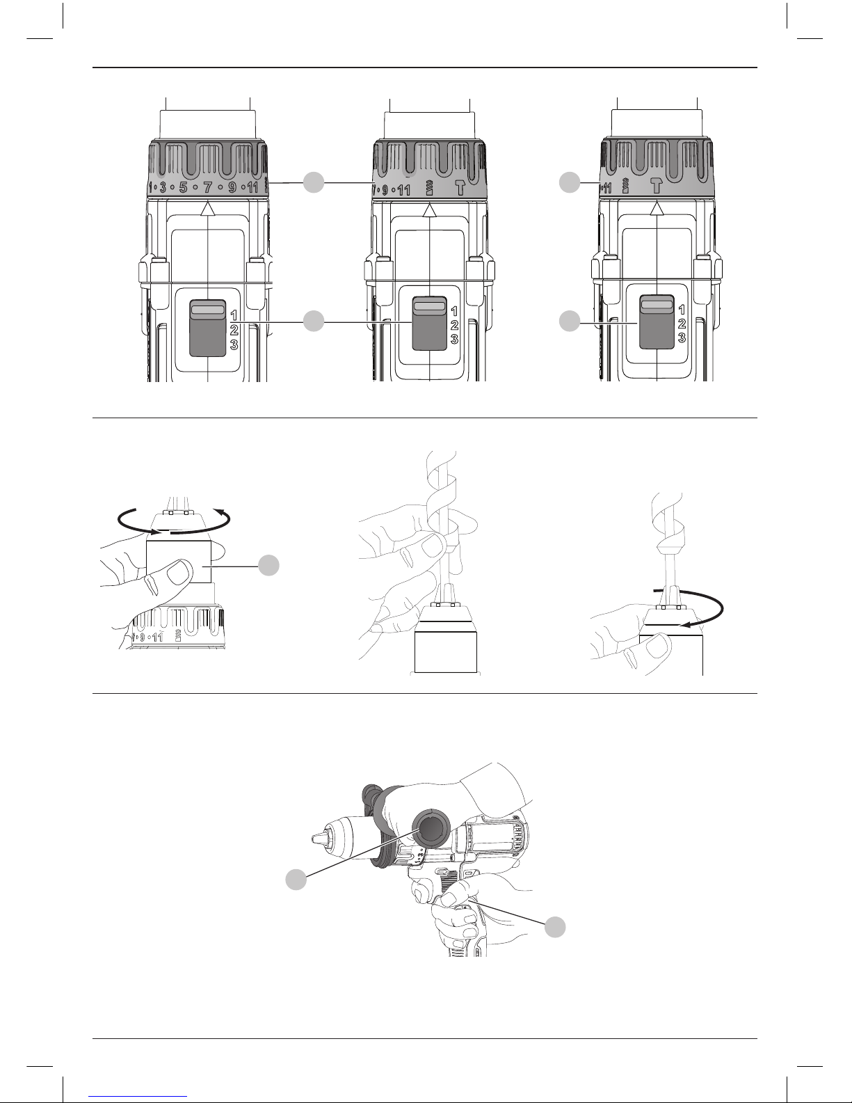
Torque Adjustment Collar/Electronic Clutch
(Fig. C–E)
Your tool has an electronic adjustable torque screwdriver
mechanism for driving and removing a wide array of fasteners.
Circling the torque adjustment collar
5
are numbers. These
numbers are used to set the clutch to deliver a torque range.
The higher the number on the collar, the higher the torque and
the larger the fastener which can be driven. To select any of the
numbers, rotate until the desired number aligns with the arrow.
Three-Speed Gearing (Fig. A, C–E)
The three-speed feature of your tool allows you to shift gears
for greater versatility. To select speed 1 (highest torque setting),
turn the tool off and permit it to stop. Slide the gear shifter
6
all the way forward. Speed 2 (middle torque and speed setting)
is in the middle position. Speed 3 (highest speed setting) is to
the rear.
NOTE: Do not change gears when the tool is running. Always
allow the drill to come to a complete stop before changing
gears. If you have trouble changing gears, make sure that the
gear shifter is engaged in one of the three speed settings.
If the speed shifter becomes stuck or is difficult to select the
desired gear, pull the trigger switch
1
to rotate the motor. Then
select the gear.
Keyless Single Sleeve Chuck (Fig. F–H)
WARNING: Do not attempt to tighten drill bits (or
any other accessory) by gripping the front part of the
chuck and turning the tool on. Damage to the chuck
and personal injury may result. Always lock off trigger
switch and disconnect tool from power source when
changingacces sories.
WARNING: Always ensure the bit is secure before starting
the tool. A loose bit may eject from tool causing possible
personal injury.
Your tool features a keyless chuck with one rotating sleeve for
one-handed operation of the chuck. To insert a drill bit or other
accessory, follow these steps.
1. Turn off tool and disconnect tool from power source.
2. Grasp the black sleeve of the chuck
4
with one hand and
use the other hand to secure the tool as shown in FigureF.
Rotate the sleeve counterclockwise (as viewed from the
front) far enough to accept the desired accessory.
3. Insert the accessory about 19 mm into the chuck (Fig.G).
Tighten securely by rotating the chuck sleeve clockwise
with one hand while holding the tool with the other hand
(Fig.H). Continue to rotate the chuck sleeve until several
ratchet clicks are heard to ensure full gripping power.
To release the accessory, repeat Steps 1 and 2 above.
Be sure to tighten chuck with one hand on the chuck sleeve and
one hand holding the tool for maximum tightness.
LED Worklight (Fig. A)
The LED worklight
3
and its worklight switch
13
are located on
the foot of the tool. The worklight is activated when the trigger
switch is depressed. The low
14
, medium
15
and spotlight
16
modes can be changed by moving the switch on the foot of the
tool. If the trigger switch remains depressed, the worklight will
remain on in all modes.
When on low
14
and medium
15
settings, the beam will
automatically turn off 20 seconds after the trigger switch
isreleased.
Spotlight Mode
The high setting
16
is the spotlight mode. The spotlight will
run for 20 minutes after the trigger switch is released. Two
minutes before the spotlight will shut off, it will flash twice and
then dim. To avoid the spotlight shutting off, lightly tap the
trigger switch.
WARNING: While using the worklight in medium or
spotlight mode, do not stare at the light or place the drill in
a position which may cause anyone to stare into the light.
Serious eye injury could result.
Page 14

12
ENGLISH
CAUTION: When using the tool as a spotlight, be sure
it is secured on a stable surface where it will not cause a
tripping or falling hazard.
CAUTION: Remove all accessories from the chuck before
using the drill as a spotlight. Personal injury or property
damage could result.
Low Battery Warning
When in spotlight mode and the battery is nearing complete
discharge, the spotlight will flash twice and then dim. After two
minutes, the battery will be completely discharged and the
drill will immediately shut down. At this point, replace with a
charged battery.
WARNING: To reduce the risk of injury, always have a
back-up battery or secondary lighting available if the
situation warrants it.
Belt Hook and Magnetic Bit Holder (Fig. A)
WARNING: To reduce the risk of serious personal
injury, turn tool off and disconnect battery pack
before making any adjustments or removing/
installing attachments or accessories.
WARNING: To reduce the risk of serious personal
injury, DO NOT suspend tool overhead or suspend
objects from the belt hook. ONLY hang tool’s belt hook
from a work belt.
WARNING: To reduce the risk of serious personal
injury, ensure the screw holding the belt hook is secure.
CAUTION: To reduce the risk of personal injury or
damage, DO NOT use the belt hook to hang the drill
while using as a spotlight.
IMPORTANT: When attaching or replacing the belt hook or
magnetic bit holder, use only the screw
11
that is provided. Be
sure to securely tighten the screw.
The belt hook
10
and magnetic bit holder
12
can be be
attached to either side of the tool using only the screw
11
provided, to accommodate left- or right- handed users. If the
hook or magnetic bit holder is not desired at all, it can be
removed from the tool.
To move belt hook or magnetic bit holder, remove the screw
11
that holds it in place then reassemble on the opposite side.
Be sure to securely tighten the screw.
OPERATION
Instructions for Use
WARNING: Always observe the safety instructions and
applicableregulations.
WARNING: To reduce the risk of serious personal
injury, turn tool off and disconnect battery pack
before making any adjustments or removing/
installing attachments or accessories. An accidental
start-up can causeinjury.
Proper Hand Position (Fig. I)
WARNING: To reduce the risk of serious personal injury,
ALWAYS use proper hand position as shown infigureI.
WARNING: To reduce the risk of serious personal
injury, ALWAYS hold securely in anticipation of a
suddenreaction.
Proper hand position requires one hand on the main handle
18
, with the other hand on the side handle
7
.
Drill Operation (Fig. D)
WARNING: To reduce the risk of serious personal
injury, turn tool off and disconnect tool from power
source before making any adjustments or removing/
installing attachments or accessories.
WARNING: TO REDUCE THE RISK OF PERSONAL
INJURY, ALWAYS ensure workpiece is anchored or
clamped firmly. If drilling thin material, use a wood “backup” block to prevent damage to the material.
1. Select the desired speed/torque range using the gear shifter
to match the speed and torque to the planned operation.
Set the torque adjustment collar
5
to the drill symbol.
2. For Wood, use twist bits, spade bits, power auger bits or
hole saws. For Metal, use high-speed steel twist drill bits
or hole saws. Use a cutting lubricant when drilling metals.
The exceptions are cast iron and brass which should be
drilleddry.
3. Always apply pressure in a straight line with the bit. Use
enough pressure to keep the drill bit biting, but do not push
hard enough to stall the motor or deflect the bit.
4. Hold tool firmly with both hands to control the twisting
action of the drill.
5. IF DRILL STALLS, it is usually because it is being
overloaded. RELEASE TRIGGER IMMEDIATELY, remove
drill bit from work, and determine cause of stalling. DO NOT
CLICK TRIGGER OFF AND ON IN AN ATTEMPT TO START
A STALLED DRILL – THIS CAN DAMAGE THE DRILL.
6. Keep the motor running when pulling the bit back out of a
drilled hole. This will help prevent jamming.
Screwdriver Operation (Fig. C)
1. Select the desired speed/torque range using the threespeed gear shifter
6
on the top of the tool. If using the
torque adjustment collar
5
, initially set the three-speed
gear shifter to speed 2 or 3. This ensures effective control
over the fastener allowing the screw to be seated correctly
and set to specification. Speed 1 will provide the same
clutching torque as speeds 2 and 3. However, for optimum
performance of the electronic clutch, speeds 2 and 3
arepreferred.
NOTE: Use the lowest torque setting (1) first and increase
the number through to the highest setting (11) to seat the
fastener at the desired depth. The lower the number, the
lower the torque output.
2. Reset the torque adjustment collar
5
to the appropriate
number setting for the torque desired. Make a few practice
runs in scrap or unseen areas to determine the proper
position of the torque adjustment collar.
NOTE: The torque adjustment collar may be set to any number
at any time.
Page 15

13
ENGLISH
Hammerdrill Operation (Fig. E)
1. Select the desired speed/torque range using the gear shifter
to match the speed and torque to the planned operation.
Set the torque adjustment collar
5
to the hammer symbol.
2. Select the high speed 3 setting by sliding the gear shifter
6
back (away form the chuck).
3. When drilling, use just enough force on the hammer to
keep it from bouncing excessively. Prolonged and too much
force on the hammer will cause slower drilling speeds and
potential overheating.
4. Drill straight, keeping the bit at a right angle to the work. Do
not exert side pressure on the bit when drilling as this will
cause clogging of the bit flutes and a slower drilling speed.
5. When drilling deep holes, if the hammer speed starts to
drop off, pull the bit partially out of the hole with the tool
still running to help clear debris from the hole.
6. For masonry, use carbide-tipped bits or masonry bits. A
smooth, even flow of dust indicates the proper drilling rate.
MAINTENANCE
Your
DeWALT
power tool has been designed to operate
over a long period of time with a minimum of maintenance.
Continuous satisfactory operation depends upon proper tool
care and regularcleaning.
WARNING: To reduce the risk of serious personal
injury, turn tool off and disconnect battery pack
before making any adjustments or removing/
installing attachments or accessories. An accidental
start-up can causeinjury.
The charger and battery pack are notserviceable.
Lubrication
Your power tool requires no additionallubrication.
Cleaning
WARNING: Blow dirt and dust out of the main housing
with dry air as often as dirt is seen collecting in and around
the air vents. Wear approved eye protection and approved
dust mask when performing thisprocedure.
WARNING: Never use solvents or other harsh chemicals
for cleaning the non-metallic parts of the tool. These
chemicals may weaken the materials used in these parts.
Use a cloth dampened only with water and mild soap.
Never let any liquid get inside the tool; never immerse any
part of the tool into aliquid.
Optional Accessories
WARNING: Since accessories, other than those offered
by
DeWALT
, have not been tested with this product, use
of such accessories with this tool could be hazardous.
To reduce the risk of injury, only
DeWALT
recommended
accessories should be used with thisproduct.
Consult your dealer for further information on the
appropriateaccessories.
Protecting the Environment
Separate collection. Products and batteries marked
with this symbol must not be disposed of with normal
household waste.
Products and batteries contain materials that can
be recovered or recycled reducing the demand for raw
materials. Please recycle electrical products and batteries
according to local provisions. Further information is available at
www.2helpU.com.
Rechargeable Battery Pack
This long life battery pack must be recharged when it fails
to produce sufficient power on jobs which were easily done
before. At the end of its technical life, discard it with due care for
our environment:
• Run the battery pack down completely, then remove it from
the tool.
• Li-Ion cells are recyclable. Take them to your dealer or a
local recycling station. The collected battery packs will be
recycled or disposed of properly.
Page 16

Belgique et
Luxembourg België
en Luxemburg
DeWALT - Belgium BVBA
Egide Walschaertsstraat 16
2800 Mechelen
Tel: NL 32 15 47 37 63
Tel: FR 32 15 47 37 64
Fax: 32 15 47 37 99
www.dewalt.be
enduser.BE@SBDinc.com
Danmark DeWALT (Stanley Black&Decker AS)
Roskildevej 22
2620 Albertslund
Tel: 70 20 15 10
Fax: 70 22 49 10
www.dewalt.dk
kundeservice.dk@sbdinc.com
Deutschland DeWALT
Richard Klinger Str. 11
65510 Idstein
Tel: 06126-21-0
Fax: 06126-21-2770
www.dewalt.de
infodwge@sbdinc.com
Ελλάς DeWALT (Ελλάς) Α.Ε.
EΔΡΑ-ΓΡΑΦΕΙΑ : Στράβωνος 7
& Λ. Βουλιαγμένης, Γλυφάδα 166 74, Αθήνα
SERVICE : Ημερος Τόπος 2 (Χάνι Αδάμ) – 193 00 Ασπρόπυργος
Τηλ: 00302108981616
Φαξ: 00302108983570
www.dewalt.gr
Greece.Service@sbdinc.com
España DeWALT Ibérica, S.C.A.
Parc de Negocios “Mas Blau”
Edificio Muntadas, c/Bergadá, 1, Of. A6
08820 El Prat de Llobregat (Barcelona)
Tel: 934 797 400
Fax: 934 797 419
www.dewalt.es
respuesta.postventa@sbdinc.com
France DeWALT
5, allée des Hêtres
BP 60105, 69579 Limonest Cedex
Tel: 04 72 20 39 20
Fax: 04 72 20 39 00
www.dewalt.fr
scufr@sbdinc.com
Schweiz
Suisse
Svizzera
DeWALT
In der Luberzen 42
8902 Urdorf
Tel: 044 - 755 60 70
Fax: 044 - 730 70 67
www.dewalt.ch
service@rofoag.ch
Ireland DeWALT
Building 4500, Kinsale Road
Cork Airport Business Park
Cork, Ireland
Tel: 00353-2781800
Fax: 01278 1811
www.dewalt.ie
Sales.ireland@sbdinc.com
Italia DeWALT
via Energypark 6
20871 Vimercate (MB), IT
Tel: 800-014353
39 039-9590200
Fax: 39 039-9590311
www.dewalt.it
Nederlands DeWALT
Netherlands BVPostbus 83,
6120 AB BORN
Tel: 31 164 283 063
Fax: 31 164 283 200
www.dewalt.nl
Norge DeWALT
Postboks 4613
0405 Oslo, Norge
Tel: 45 25 13 00
Fax: 45 25 08 00
www.dewalt.no
kundeservice.no@sbdinc.com
Österreich DeWALT
Werkzeug Vertriebsges m.b.H
Oberlaaerstrasse 248, A-1230 Wien
Tel: 01 - 66116 - 0
Fax: 01 - 66116 - 614
www.dewalt.at
service.austria@sbdinc.com
Portugal DeWALT
Ed. D Dinis, Quina da Fonte
Rua dos Malhoes 2 2A 2º Esq.
Oeiras e S. Juliao da Barra, paço de Arcos e Caxias
2770 071 Paço de Arcos
Tel: +351 214667500
Fax: +351214667580
www.dewalt.pt
resposta.posvenda@sbdinc.com
Suomi DeWALT
PL47
00521 Helsinki, Suomi
Puh: 010 400 4333
Faksi: 0800 411 340
www.dewalt.fi
asiakaspalvelu.fi@sbdinc.com
Sverige DeWALT
BOX 94
43122 Mölndal
Sverige
Tel: 031 68 61 60
Fax: 031 68 60 08
www.dewalt.se
kundservice.se@sbdinc.com
Türkiye KALE Hırdavat ve Makina A.Ş.
Defterdar Mah. Savaklar Cad. No:15
Edirnekapı / Eyüp / İSTANBUL 34050 TÜRKİYE
Tel: 0212 533 52 55
Faks: 0212 533 10 05
www.dewalt.com.tr
United
Kingdom
DeWALT, 210 Bath Road;
Slough, Berks SL1 3YD
Tel: 01753-567055
Fax: 01753-572112
www.dewalt.co.uk
emeaservice@sbdinc.com
Australia DeWALT
810 Whitehorse Road Box Hill
VIC 3103 Australia
Tel: Aust 1800 338 002
Tel: NZ 0800 339 258
www.dewalt.com.au
www.dewalt.co.nz
Middle East Africa DeWALT
P.O. Box - 17164,
Jebel Ali Free Zone (South), Dubai, UAE
Tel: 971 4 812 7400
Fax: 971 4 2822765
www.dewalt.ae
Service.MEA@sbdinc.com
N490636
09/16
 Loading...