

Page 1

If you have questions or comments, contact us.
Pour toute question ou tout commentaire, nous contacter.
Si tiene dudas o comentarios, contáctenos.
1-800-4-DEWALT • www.dewalt.com
INSTRUCTION MANUAL
GUIDE D'UTILISATION
INSTRUCTIVO DE OPERACIÓN, CENTROS DE SERVICIO Y PÓLIZA DE
GARANTÍA. ADVERTENCIA: LÉASE ESTE INSTRUCTIVO ANTES DE
USAR EL PRODUCTO.
MANUAL DE INSTRUCCIONES
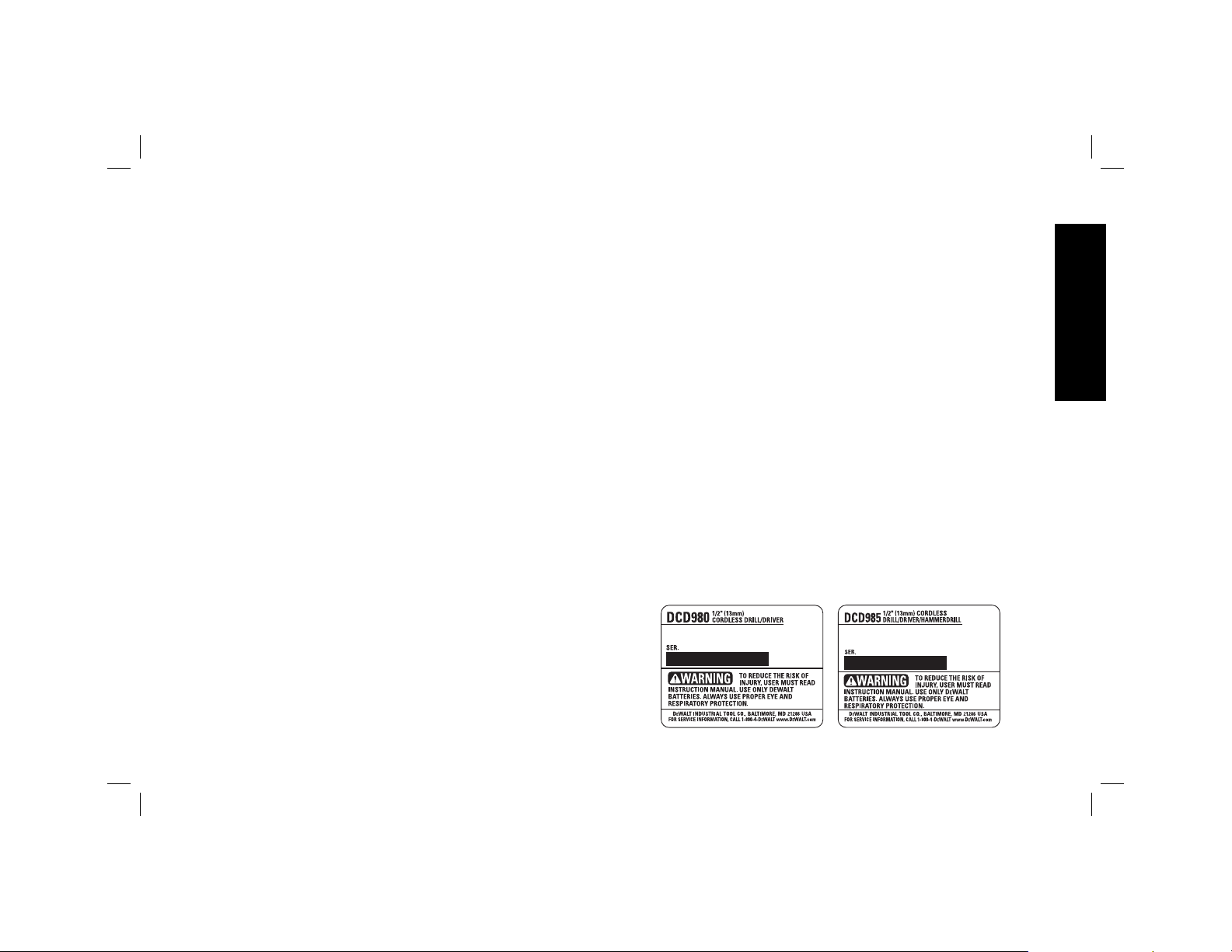
DCD980 20V Max* Heavy-Duty 1/2" (13 mm) Cordless Drill/Driver
DCD985 20V Max* Heavy-Duty 1/2" (13 mm) Cordless Hammerdrill/Drill/Driver
DCD980 Perceuse/visseuse industrielle sans fil 13mm (1/2po) de 20 V max*
DCD985 Marteau perforateur/Perceuse/Visseuse industrielsans fil 13 mm (1/2 po) de 20 V max*
Taladro/destornillador inalámbrico de 1/2 pulg. (13 mm) para trabajos pesados de 20 V Máx* DCD980
Taladro percusor/taladro/destornillador inalámbrico de 1/2 pulg. (13 mm) para trabajos pesados de 20 V Máx* DCD985
Page 2

Page 3

Defi nitions: Safety Guidelines
The definitions below describe the level of severity for each
signal word. Please read the manual and pay attention to these
symbols.
DANGER: Indicates an imminently hazardous situation
which, if not avoided, will result in death or serious injury.
WARNING: Indicates a potentially hazardous situation which,
if not avoided, could result in death or serious injury.
CAUTION: Indicates a potentially hazardous situation which, if
not avoided, may result in minor or moderate injury.
NOTICE: Indicates a practice not related to personal injury
which, if not avoided, may result in property damage.
IF YOU HAVE ANY QUESTIONS OR COMMENTS ABOUT THIS OR
EWALT TOOL, CALL US TOLL FREE AT: 1-800-4-DEWALT
ANY D
(1-800-433-9258).
WARNING: To reduce the risk of injury, read the instruction
manual.
General Power Tool Safety Warnings
WARNING! Read all safety warnings and all instructions.
Failure to follow the warnings and instructions may result in
electric shock, fire and/or serious injury.
SAVE ALL WARNINGS AND INSTRUCTIONS
FOR FUTURE REFERENCE
The term “power tool” in the warnings refers to your mains-operated
(corded) power tool or battery-operated (cordless) power tool.
1) WORK AREA SAFETY
a) Keep work area clean and well lit. Cluttered or dark areas
invite accidents.
b) Do not operate power tools in explosive atmospheres,
such as in the presence of flammable liquids, gases or
dust. Power tools create sparks which may ignite the dust or
fumes.
c) Keep children and bystanders away while operating a
power tool. Distractions can cause you to lose control.
2) ELECTRICAL SAFETY
a) Power tool plugs must match the outlet. Never modify
the plug in any way. Do not use any adapter plugs with
earthed (grounded) power tools. Unmodified plugs and
matching outlets will reduce risk of electric shock.
b) Avoid body contact with earthed or grounded surfaces
such as pipes, radiators, ranges and refrigerators. There
is an increased risk of electric shock if your body is earthed or
grounded.
c) Do not expose power tools to rain or wet conditions.
Water entering a power tool will increase the risk of electric
shock.
d) Do not abuse the cord. Never use the cord for carrying,
pulling or unplugging the power tool. Keep cord away
from heat, oil, sharp edges or moving parts. Damaged or
entangled cords increase the risk of electric shock.
e) When operating a power tool outdoors, use an extension
cord suitable for outdoor use. Use of a cord suitable for
outdoor use reduces the risk of electric shock.
f) If operating a power tool in a damp location is unavoidable,
use a ground fault circuit interrupter (GFCI) protected
supply. Use of a GFCI reduces the risk of electric shock.
English
1
Page 4

3) PERSONAL SAFETY
a) Stay alert, watch what you are doing and use common
sense when operating a power tool. Do not use a power
tool while you are tired or under the influence of drugs,
alcohol or medication. A moment of inattention while
operating power tools may result in serious personal injury.
b) Use personal protective equipment. Always wear eye
English
protection. Protective equipment such as dust mask, nonskid safety shoes, hard hat, or hearing protection used for
appropriate conditions will reduce personal injuries.
c) Prevent unintentional starting. Ensure the switch is in
the off position before connecting to power source and/
or battery pack, picking up or carrying the tool. Carrying
power tools with your finger on the switch or energizing power
tools that have the switch on invites accidents.
d) Remove any adjusting key or wrench before turning the
power tool on. A wrench or a key left attached to a rotating
part of the power tool may result in personal injury.
e) Do not overreach. Keep proper footing and balance at
all times. This enables better control of the power tool in
unexpected situations.
f) Dress properly. Do not wear loose clothing or jewelry.
Keep your hair, clothing and gloves away from moving
parts. Loose clothes, jewelry or long hair can be caught in
moving parts.
g) If devices are provided for the connection of dust
extraction and collection facilities, ensure these are
connected and properly used. Use of dust collection can
reduce dust-related hazards.
4) POWER TOOL USE AND CARE
a) Do not force the power tool. Use the correct power tool
for your application. The correct power tool will do the job
better and safer at the rate for which it was designed.
b) Do not use the power tool if the switch does not turn it
on and off. Any power tool that cannot be controlled with the
switch is dangerous and must be repaired.
c) Disconnect the plug from the power source and/or the
battery pack from the power tool before making any
adjustments, changing accessories, or storing power
tools. Such preventive safety measures reduce the risk of
starting the power tool accidentally.
d) Store idle power tools out of the reach of children and do
not allow persons unfamiliar with the power tool or these
instructions to operate the power tool. Power tools are
dangerous in the hands of untrained users.
e) Maintain power tools. Check for misalignment or binding
of moving parts, breakage of parts and any other condition
that may affect the power tool’s operation. If damaged,
have the power tool repaired before use. Many accidents
are caused by poorly maintained power tools.
f) Keep cutting tools sharp and clean. Properly maintained
cutting tools with sharp cutting edges are less likely to bind and
are easier to control.
g) Use the power tool, accessories and tool bits, etc. in
accordance with these instructions, taking into account
the working conditions and the work to be performed.
Use of the power tool for operations different from those
intended could result in a hazardous situation.
5) BATTERY TOOL USE AND CARE
a) Recharge only with the charger specified by the
manufacturer. A charger that is suitable for one type of
battery pack may create a risk of fire when used with another
battery pack.
b) Use power tools only with specifically designated battery
packs. Use of any other battery packs may create a risk of
injury and fire.
2
Page 5

c) When battery pack is not in use, keep it away from other
metal objects like paper clips, coins, keys, nails, screws,
or other small metal objects that can make a connection
from one terminal to another. Shorting the battery terminals
together may cause burns or a fire.
d) Under abusive conditions, liquid may be ejected from
the battery; avoid contact. If contact accidentally occurs,
flush with water. If liquid contacts eyes, additionally seek
medical help. Liquid ejected from the battery may cause
irritation or burns.
6) SERVICE
a) Have your power tool serviced by a qualified repair
person using only identical replacement parts. This will
ensure that the safety of the power tool is maintained.
Drill/Driver/Hammerdrill Safety Warnings
• Wear ear protectors when impact drilling. Exposure to noise
can cause hearing loss.
• Use auxiliary handle(s), if supplied with the tool. Loss of
control can cause personal injury.
• Hold power tool by insulated gripping surfaces, when
performing an operation where the cutting accessory may
contact hidden wiring. Cutting accessory contacting a “live” wire
may make exposed metal parts of the power tool “live” and could
give the operator an electric shock.
• Use clamps or other practical way to secure and support
the workpiece to a stable platform. Holding the work by hand
or against your body is unstable and may lead to loss of control.
• Wear safety goggles or other eye protection. Hammering and
drilling operations cause chips to fly. Flying particles can cause
permanent eye damage.
• Always use the side handle supplied with the tool. Keep a
firm grip on the tool at all times. Do not attempt to operate
this tool without holding it with both hands. Operating this
tool with one hand will result in loss of control. Breaking through or
encountering hard materials such as re-bar may be hazardous as
well.
• Accessories and tool may get hot during operation.
Wear gloves when handling them if performing heat producing
applications such as hammerdrilling and drilling metals.
• Do not operate this tool for long periods of time. Vibration
caused by hammer action may be harmful to your hands and arms.
Use gloves to provide extra cushion and limit exposure by taking
frequent rest periods.
• Air vents often cover moving parts and should be avoided.
Loose clothes, jewelry or long hair can be caught in moving parts.
WARNING: ALWAYS use safety glasses. Everyday eyeglasses
are NOT safety glasses. Also use face or dust mask if cutting
operation is dusty. ALWAYS WEAR CERTIFIED SAFETY EQUIPMENT:
• ANSI Z87.1 eye protection (CAN/CSA Z94.3),
• ANSI S12.6 (S3.19) hearing protection,
• NIOSH/OSHA/MSHA respiratory protection.
WARNING: Some dust created by power sanding, sawing,
grinding, drilling, and other construction activities contains chemicals
known to the State of California to cause cancer, birth defects or
other reproductive harm. Some examples of these chemicals are:
• lead from lead-based paints,
• crystalline silica from bricks and cement and other masonry
products, and
• arsenic and chromium from chemically-treated lumber.
Your risk from these exposures varies, depending on how often you
do this type of work. To reduce your exposure to these chemicals:
work in a well ventilated area, and work with approved safety
equipment, such as those dust masks that are specially designed to
filter out microscopic particles.
English
3
Page 6

• Avoid prolonged contact with dust from power sanding,
.....................
sawing, grinding, drilling, and other construction activities.
Wear protective clothing and wash exposed areas with soap
and water. Allowing dust to get into your mouth, eyes, or lay on
the skin may promote absorption of harmful chemicals.
WARNING: Use of this tool can generate and/or disperse dust,
which may cause serious and permanent respiratory or other injury.
Always use NIOSH/OSHA approved respiratory protection
English
appropriate for the dust exposure. Direct particles away from face
and body.
WARNING: ALWAYS wear proper personal hearing protection
that conforms to ANSI S12.6 (S3.19) during use. Under some
conditions and duration of use, noise from this product may
contribute to hearing loss.
CAUTION: When not in use, place tool on its side on a stable
surface where it will not cause a tripping or falling hazard.
Some tools with large battery packs will stand upright on the battery
pack but may be easily knocked over.
• The label on your tool may include the following symbols. The
symbols and their definitions are as follows:
V ................... volts A ......................amperes
Hz ................. hertz W .....................watts
min ............... minutes
or DC ...direct current current
.................Class I Construction or AC/DC ...alternating
(grounded) ........................or direct
................. Class II Construction current
(double insulated) no ....................no load
…/min ..........per minute speed
or AC ..........alternating
BPM .............beats per minute n ......................rated
IPM ............... impacts per minute
RPM ............. revolutions per
minute terminal
sfpm ............. surface feet
..................... per minute symbol
SPM .............strokes per minute
........................speed
.....................earthing
.....................safety alert
Important Safety Instructions for All
Battery Packs
When ordering replacement battery packs, be sure to include the
catalog number and voltage. Consult the chart at the end of this
manual for compatibility of chargers and battery packs.
The battery pack is not fully charged out of the carton. Before using
the battery pack and charger, read the safety instructions below and
then follow charging procedures outlined.
READ ALL INSTRUCTIONS
• Do not charge or use the battery pack in explosive
atmospheres, such as in the presence of flammable liquids,
gases or dust. Inserting or removing the battery pack from the
charger may ignite the dust or fumes.
• NEVER force the battery pack into the charger. DO NOT
modify the battery pack in any way to fit into a noncompatible charger as battery pack may rupture causing
serious personal injury. Consult the chart at the end of this
manual for compatibility of batteries and chargers.
• Charge the battery packs only in designated D
• DO NOT splash or immerse in water or other liquids.
• Do not store or use the tool and battery pack in locations
where the temperature may reach or exceed 105°F (40 °C)
EWALT chargers.
4
Page 7

(such as outside sheds or metal buildings in summer). For
best life store battery packs in a cool, dry location.
NOTE: Do not store the battery packs in a tool with the
trigger switch locked on. Never tape the trigger switch in the
ON position.
WARNING: Fire hazard. Never attempt to open the battery pack
for any reason. If the battery pack case is cracked or damaged, do
not insert into the charger. Do not crush, drop or damage the battery
pack. Do not use a battery pack or charger that has received a sharp
blow, been dropped, run over or damaged in any way (e.g., pierced
with a nail, hit with a hammer, stepped on). Damaged battery packs
should be returned to the service center for recycling.
WARNING: Fire hazard. Do not store or carry the battery
pack so that metal objects can contact exposed battery
terminals. For example, do not place the battery pack in aprons,
pockets, tool boxes, product kit boxes, drawers, etc., with loose
nails, screws, keys, etc. Transporting batteries can possibly
cause fires if the battery terminals inadvertently come in
contact with conductive materials such as keys, coins, hand
tools and the like. The US Department of Transportation Hazardous
Material Regulations (HMR) actually prohibit transporting batteries in
commerce or on airplanes (e.g., packed in suitcases and carry-on
luggage) UNLESS they are properly protected from short circuits.
So when transporting individual battery packs, make sure that the
battery terminals are protected and well insulated from materials that
could contact them and cause a short circuit.
SPECIFIC SAFETY INSTRUCTIONS FOR LITHIUM ION (Li-Ion)
• Do not incinerate the battery pack even if it is severely
damaged or is completely worn out. The battery pack can
explode in a fire. Toxic fumes and materials are created when
lithium ion battery packs are burned.
• If battery contents come into contact with the skin,
immediately wash area with mild soap and water. If battery
liquid gets into the eye, rinse water over the open eye for 15
minutes or until irritation ceases. If medical attention is needed,
the battery electrolyte is composed of a mixture of liquid organic
carbonates and lithium salts.
• Contents of opened battery cells may cause respiratory
irritation. Provide fresh air. If symptoms persist, seek medical
attention.
WARNING: Burn hazard. Battery liquid may be flammable if
exposed to spark or flame.
The RBRC™ Seal
The RBRC™ (Rechargeable Battery Recycling
Corp oration) Seal on the nickel cadmium, nickel metal
hydride or lithium ion batteries (or battery packs) indicate
that the costs to recycle these batteries (or battery
packs) at the end of their useful life have already been
paid by D
spent nickel cadmium, nickel metal hydride or lithium ion batteries in
the trash or municipal solid waste stream and the RBRC program
provides an environmentally conscious alternative.
RBRC™, in cooperation with D
established programs in the United States and Canada to facilitate
the collection of spent nickel cadmium, nickel metal hydride or lithium
ion batteries. Help protect our environment and conserve natural
resources by returning the spent nickel cadmium, nickel metal hydride
or lithium ion batteries to an authorized D
to your local retailer for recycling. You may also contact your local
recycling center for information on where to drop off the spent battery.
RBRC™ is a registered trademark of the Rechargeable Battery
Recycling Corporation.
EWALT. In some areas, it is illegal to place
EWALT and other battery users, has
EWALT service center or
English
5
Page 8

Important Safety Instructions for All
Battery Chargers
SAVE THESE INSTRUCTIONS: This manual contains important
safety and operating instructions for battery chargers.
• Before using the charger, read all instructions and cautionary
markings on the charger, battery pack and product using the
battery pack.
English
WARNING: Shock hazard. Do not allow any liquid to get inside the
charger. Electric shock may result.
CAUTION: Burn hazard. To reduce the risk of injury, charge only
EWALT rechargeable battery packs. Other types of batteries may
D
overheat and burst resulting in personal injury and property damage.
NOTICE: Under certain conditions, with the charger plugged into the
power supply, the charger can be shorted by foreign material. Foreign
materials of a conductive nature, such as, but not limited to, grinding
dust, metal chips, steel wool, aluminum foil or any buildup of metallic
particles should be kept away from the charger cavities. Always unplug
the charger from the power supply when there is no battery pack in the
cavity. Unplug the charger before attempting to clean.
• DO NOT attempt to charge the battery pack with any
chargers other than the ones in this manual. The charger and
battery pack are specifically designed to work together.
• These chargers are not intended for any uses other than
charging D
result in risk of fire, electric shock or electrocution.
• Do not expose the charger to rain or snow.
• Pull by the plug rather than the cord when disconnecting
the charger. This will reduce the risk of damage to the electric plug
and cord.
• Make sure that the cord is located so that it will not be
stepped on, tripped over or otherwise subjected to damage
or stress.
EWALT rechargeable batteries. Any other uses may
• Do not use an extension cord unless it is absolutely
necessary. Use of improper extension cord could result in risk of
fire, electric shock or electrocution.
• When operating a charger outdoors, always provide a dry
location and use an extension cord suitable for outdoor use.
Use of a cord suitable for outdoor use reduces the risk of electric
shock.
• An extension cord must have adequate wire size (AWG or
American Wire Gauge) for safety. The smaller the gauge number
of the wire, the greater the capacity of the cable, that is, 16 gauge
has more capacity than 18 gauge. An undersized cord will cause a
drop in line voltage resulting in loss of power and overheating. When
using more than one extension to make up the total length, be sure
each individual extension contains at least the minimum wire size.
The following table shows the correct size to use depending on cord
length and nameplate ampere rating. If in doubt, use the next heavier
gauge. The lower the gauge number, the heavier the cord.
Minimum Gauge for Cord Sets
Volts Total Length of Cord in Feet (meters)
Ampere Rating
More
Not More
Than
10 12 16 16 14 12
12 16 14 12 Not Recommended
Than
0 6 18 16 16 14
610 18 16 14 12
120V 25 (7.6) 50 (15.2) 100 (30.5) 150 (45.7)
240V 50 (15.2) 100 (30.5) 200 (61.0) 300 (91.4)
AWG
• Do not place any object on top of the charger or place the
charger on a soft surface that might block the ventilation
slots and result in excessive internal heat. Place the charger
in a position away from any heat source. The charger is ventilated
through slots in the top and the bottom of the housing.
• Do not operate the charger with a damaged cord or plug.
6
Page 9
• Do not operate the charger if it has received a sharp blow,
been dropped or otherwise damaged in any way. Take it to an
authorized service center.
• Do not disassemble the charger; take it to an authorized
service center when service or repair is required. Incorrect
reassembly may result in a risk of electric shock, electrocution or fire.
• Disconnect the charger from the outlet before attempting
any cleaning. This will reduce the risk of electric shock.
Removing the battery pack will not reduce this risk.
• NEVER attempt to connect 2 chargers together.
• The charger is designed to operate on standard 120V
household electrical power. Do not attempt to use it on any
other voltage. This does not apply to the vehicular charger.
Chargers
Your tool uses a DEWALT charger. Be sure to read all safety instructions
before using your charger. Consult the chart at the end of this manual
for compatibility of chargers and battery packs.
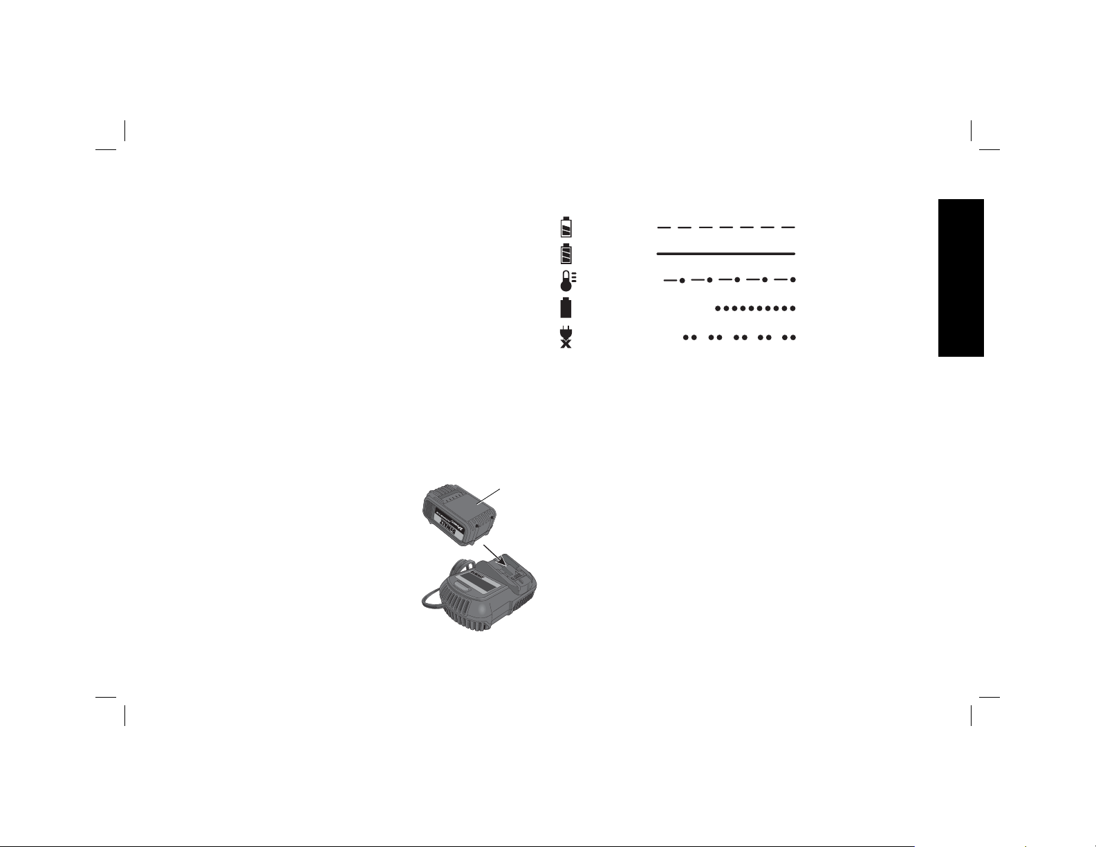
Charging Procedure (Fig. 1)
1. Plug the charger into an appropriate
outlet before inserting the battery
pack.
2. Insert the battery pack (I) into the
charger, as shown in Figure 1,
making sure the pack is fully seated
in charger. The red (charging) light
will blink continuously, indicating
that the charging process has
started.
3. The completion of charge will be
indicated by the red light remaining
ON continuously. The pack is fully
charged and may be used at this time or left in the charger.
FIG. 1
I
Indicator Light Operation
PACK CHARGING
PACK CHARGED
HOT/COLD DELAY
PROBLEM PACK OR CHARGER
x
PROBLEM POWERLINE
Charge Indicators
This charger is designed to detect certain problems that can arise.
Problems are indicated by the red light flashing at a fast rate. If this
occurs, re-insert the battery pack into the charger. If the problem
persists, try a different battery pack to determine if the charger is
working properly. If the new pack charges correctly, then the original
pack is defective and should be returned to a service center or other
collection site for recycling. If the new battery pack elicits the same
trouble indication as the original, have the charger and the battery pack
tested at an authorized service center.
HOT/COLD DELAY
This charger has a hot/cold delay feature: when the charger detects a
battery that is hot, it automatically starts a delay, suspending charging
until the battery has cooled. After the battery has cooled, the charger
automatically switches to the pack charging mode. This feature
ensures maximum battery life. The red light flashes long, then short
while in the hot/cold delay mode.
LEAVING THE BATTERY PACK IN THE CHARGER
The charger and battery pack can be left connected with the charge
indicator showing Pack Charged.
English
7
Page 10

WEAK BATTERY PACKS: Weak batteries will continue to function
but should not be expected to perform as much work.
FAULTY BATTERY PACKS: This charger will not charge a faulty
battery pack. The charger will indicate faulty battery pack by refusing
to light or by displaying problem pack or charger.
NOTE: This could also mean a problem with a charger.
PROBLEM POWER LINE
English
Some chargers have a problem powerline indicator. When the charger
is used with some portable power sources such as generators or
sources that convert DC to AC, the charger may temporarily suspend
operation, flashing the red light with two fast blinks followed by a pause.
This indicates the power source is out of limits.
Important Charging Notes
1. Longest life and best performance can be obtained if the battery
pack is charged when the air temperature is between 65°F and
75°F (18 ° – 24 °C). DO NOT charge the battery pack in an air
temperature below +40°F (+4.5°C), or above +105°F (+40.5°C).
This is important and will prevent serious damage to the battery
pack.
2. The charger and battery pack may become warm to the touch
while charging. This is a normal condition, and does not indicate
a problem. To facilitate the cooling of the battery pack after use,
avoid placing the charger or battery pack in a warm environment
such as in a metal shed or an uninsulated trailer.
3. A cold battery pack will charge at about half the rate of a warm
battery pack. The battery pack will charge at that slower rate
throughout the entire charging cycle and will not return to
maximum charge rate even if the battery pack warms.
4. If the battery pack does not charge properly:
a. Check operation of receptacle by plugging in a lamp or other
appliance;
b. Check to see if receptacle is connected to a light switch which
turns power off when you turn out the lights;
c. Move the charger and battery pack to a location where the
surrounding air temperature is approximately 65 °F – 75 °F
(18° – 24°C);
d. If charging problems persist, take the tool, battery pack and
charger to your local service center.
5. The battery pack should be recharged when it fails to produce
sufficient power on jobs which were easily done previously. DO
NOT CONTINUE to use under these conditions. Follow the
charging procedure. You may also charge a partially used pack
whenever you desire with no adverse effect on the battery pack.
6. Foreign materials of a conductive nature such as, but not limited
to, grinding dust, metal chips, steel wool, aluminum foil, or any
buildup of metallic particles should be kept away from charger
cavities. Always unplug the charger from the power supply when
there is no battery pack in the cavity. Unplug the charger before
attempting to clean.
7. Do not freeze or immerse the charger in water or any other liquid.
WARNING: Shock hazard. Don’t allow any liquid to get inside the
charger. Electric shock may result.
WARNING: Burn hazard. Do not submerge the battery pack in
any liquid or allow any liquid to enter the battery pack. Never attempt
to open the battery pack for any reason. If the plastic housing of the
battery pack breaks or cracks, return to a service center for recycling.
Storage Recommendations
1. The best storage place is one that is cool and dry, away from direct
sunlight and excess heat or cold.
2. For long storage, it is recommended to store a fully charged
battery pack in a cool dry place out of the charger for optimal
results.
8
Page 11
NOTE: Battery packs should not be stored completely depleted of
charge. The battery pack will need to be recharged before use.
SAVE THESE INSTRUCTIONS
FOR FUTURE USE
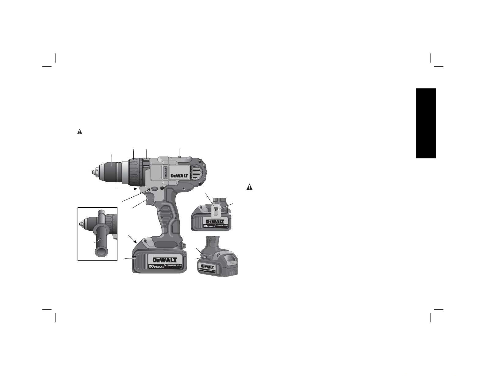
COMPONENTS (Fig. 2)
WARNING: Never modify the power tool or any part of it. Damage
or personal injury could result.
E
FIG. 2
D
C
B
A
J
H
I
F
G
K
M
L
M
A. Trigger switch H. Side handle
B. Forward/reverse control button I. Battery pack
C. Worklight J. Battery release button
D. Chuck K. Belt hook
E. Torque adjustment collar L. Bit clip
F. Mode control collar M. Screw
G. Gear shifter
Variable Speed Trigger Switch (Fig. 2)
To turn the tool on, squeeze the trigger switch (A). To turn the tool
off, release the trigger switch. Your tool is equipped with a brake. The
chuck will stop as soon as the trigger switch is fully released.
NOTE: Continuous use in variable speed range is not recommended.
It may damage the switch and should be avoided.
Side Handle (Fig. 2)
WARNING: To reduce the risk of personal injury, ALWAYS
operate the tool with the side handle properly installed. Failure to do
so may result in the side handle slipping during tool operation and
subsequent loss of control. Hold tool with both hands to maximize
control.
Side handle (H) clamps to the front of the gear case and may be rotated
360° to permit right- or left-hand use. Side handle must be tightened
sufficiently to resist the twisting action of the tool if the accessory binds
or stalls. Be sure to grip the side handle at the far end to control the tool
during a stall.
If model is not equipped with side handle, grip drill with one hand on
the handle and one hand on the battery pack.
NOTE: Side handle comes equipped on both models.
English
9
Page 12
Forward/Reverse Control Button (Fig. 2)
A forward/reverse control button (B) determines the direction of the
tool and also serves as a lock-off button.
To select forward rotation, release the trigger switch and depress the
for ward/re verse control button on the right side of the tool.
To select reverse, release the trigger switch and depress the forward/
reverse control button on the left side of the tool.
English
The center position of the control button locks the tool in the OFF
position. When changing the position of the control button, be sure
the trigger is released.
NOTE: The first time the tool is run after changing the direction of
rotation, you may hear a click on start up. This is normal and does not
indicate a problem.
Worklight (Fig. 2)
There is a worklight (C) located just above the trigger switch (A). The
worklight is activated when the trigger switch is depressed, and will
automatically turn off 20 seconds after the trigger switch is released.
If the trigger switch remains depressed, the worklight will remain on.
NOTE: The worklight is for lighting the immediate work surface and is
not intended to be used as a flashlight.
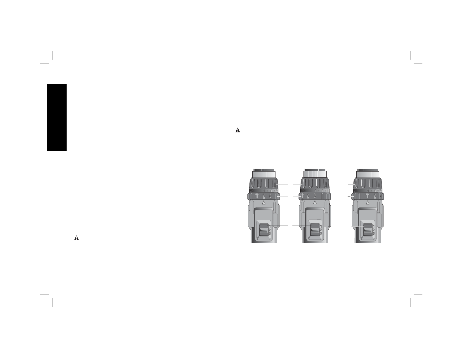
Mode Control Collar (Fig. 3–5)
Your drill is equipped with a separate mode control collar (F) to switch
between drilling, screwdriving and hammerdrilling mode.
DRILLING (FIG. 3)
CAUTION: When the mode collar is in the drill/hammerdrill mode,
the drill will not clutch out regardless of the position of the torque
adjustment collar (E).
Rotate the mode control collar (F) so the drill symbol is aligned with
the arrow.
NOTE: The torque adjustment collar (E) may be set on any number.
SCREWDRIVING (FIG. 4)
Rotate the mode control collar (F) so the screw symbol is aligned
with the arrow.
NOTE: The torque adjustment collar may be set to any number at any
time. However, the torque adjustment collar is only engaged during
screwdriving mode and not in drill and hammerdrill modes.
HAMMERDRILLING (FIG. 5)
CAUTION: When the mode collar is in the drill/hammerdrill mode,
the drill will not clutch out regardless of the position of the torque
adjustment collar (E).
Rotate the mode control collar (F) so the hammer symbol is aligned
with the arrow.
NOTE: The torque adjustment collar (E) may be set on any number.
FIG. 3
DRILLING
FIG. 4
E
F
G
SCREWDRIVING
FIG. 5
E
F
G
HAMMERDRILLING
10
Page 13
Torque Adjustment Collar (Fig. 3–5)
Your tool has an adjustable torque screwdriver mechanism for driving
and removing a wide array of fastener shapes and sizes. Circling the
torque adjustment collar (E) are numbers. These numbers are used to
set the clutch to deliver a torque range. The higher the number on the
collar, the higher the torque and the larger the fastener which can be
driven. To select any of the numbers, rotate until the desired number
aligns with the arrow.
Three-Speed Gearing (Fig. 3–5)
The three-speed feature of your tool allows you to shift gears for greater
versatility. To select speed 1 (highest torque setting), turn the tool off and
permit it to stop. Slide the gear shifter (G) all the way forward. Speed
2 (middle torque and speed setting) is in the middle position. Speed 3
(highest speed setting) is to the rear.
NOTE: Do not change gears when the tool is running. Always allow
the drill to come to a complete stop before changing gears. If you have
trouble changing gears, make sure that the gear shifter is engaged in
one of the three speed settings.
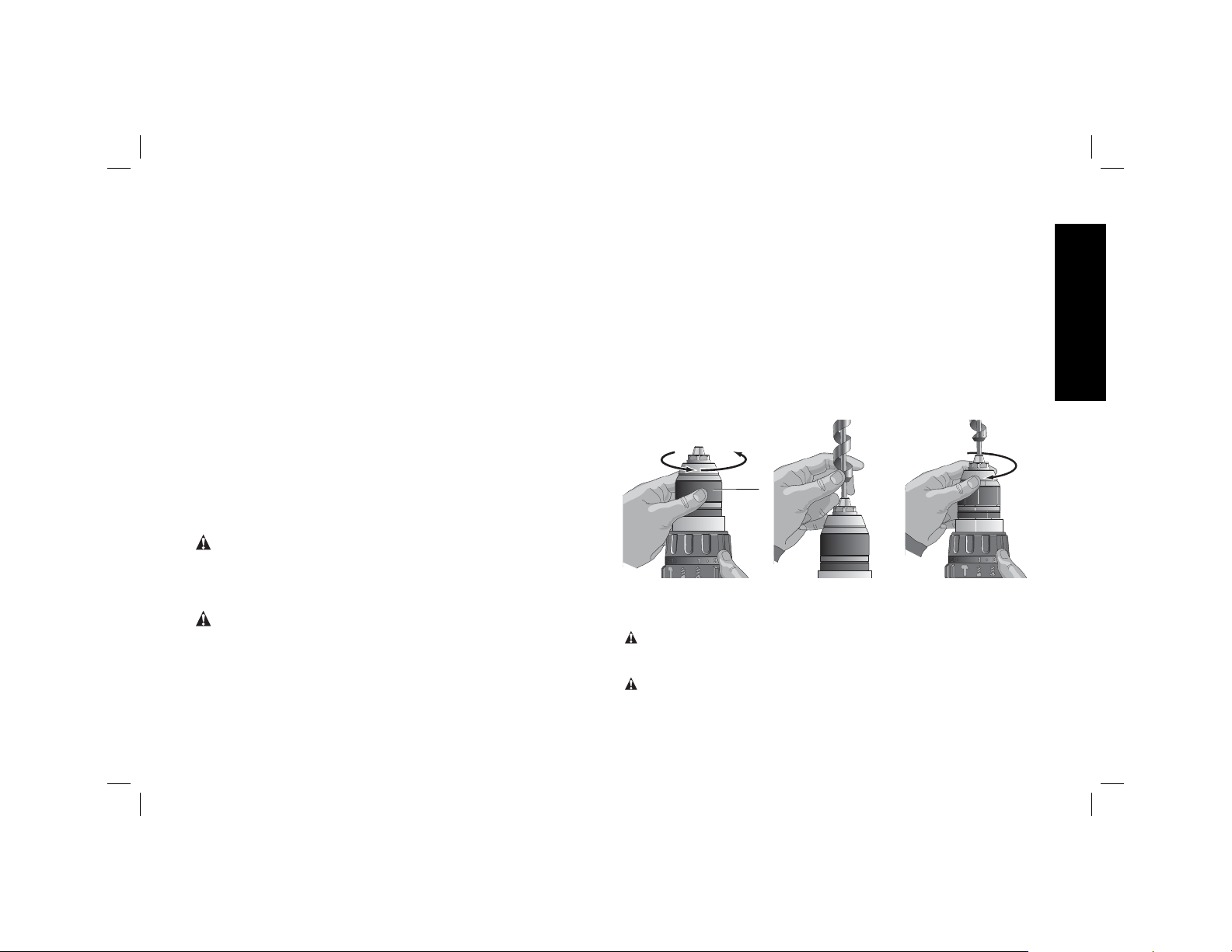
Keyless Single Sleeve Chuck (Fig. 6–8)
WARNING: Do not attempt to tighten drill bits (or any other
accessory) by gripping the front part of the chuck and turning the
tool on. Damage to the chuck and personal injury may result. Always
lock off trigger switch and disconnect tool from power source when
changing acces sories.
WARNING: Always ensure the bit is secure before starting the
tool. A loose bit may eject from tool causing possible personal injury.
Your tool features a keyless chuck with one rotating sleeve for onehanded operation of the chuck. To insert a drill bit or other accessory,
follow these steps.
1. Turn tool off and disconnect tool from power source.
2. Grasp the black sleeve of the chuck (D) with one hand and use
the other hand to secure the tool as shown in Figure 6. Rotate the
sleeve counterclockwise (as viewed from the front) far enough to
accept the desired accessory.
3. Insert the accessory about 3/4" (19 mm) into the chuck and
tighten securely by rotating the chuck sleeve clockwise with one
hand while holding the tool with the other hand. Continue to rotate
the chuck sleeve until several ratchet clicks are heard to ensure full
gripping power.
Be sure to tighten chuck with one hand on the chuck sleeve and one
hand holding the tool for maximum tightness.
To release the accessory, repeat Steps 1 and 2 above.
FIG. 6
FIG. 7
D
FIG. 8
Belt Hook and Bit Clip (Optional
Accessories) (Fig. 2)
WARNING: To reduce the risk of serious personal injury,
turn tool off and disconnect battery pack before making any
adjustments or removing/installing attachments or accessories.
WARNING: To reduce the risk of serious personal injury, DO
NOT suspend tool overhead or suspend objects from the belt hook.
ONLY hang tool’s belt hook from a work belt.
English
11
Page 14
WARNING: To reduce the risk of serious personal injury,
ensure the screw holding the belt hook is secure.
IMPORTANT: When attaching or replacing the belt hook (K) or bit clip
(L), use only the screw (M) that is provided. Be sure to securely tighten
the screw.
The belt hook (K) and bit clip (L) can be be attached to either side of
the tool using only the screw (M) provided, to accommodate left- or
right- handed users. If the hook or bit clip is not desired at all, it can
English
be removed from the tool.
To move belt hook or bit clip, remove the screw (M) that holds it in
place then reassemble on the opposite side. Be sure to securely
tighten the screw.
OPERATION
WARNING: To reduce the risk of serious personal injury,
turn tool off and disconnect tool from power source before
making any adjustments or removing/installing attachments
or accessories.
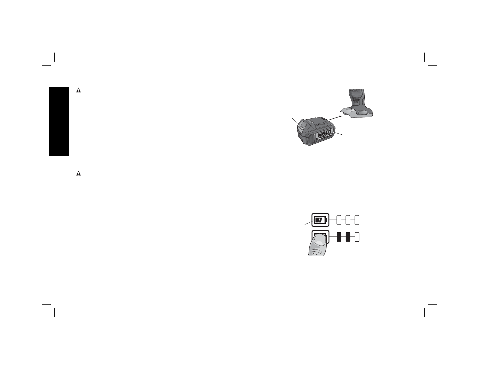
Installing and Removing the Battery Pack
(Fig. 9)
NOTE: For best results, make sure your battery pack is fully charged.
To install the battery pack (I) into the tool handle, align the battery pack
with the rails inside the tool’s handle and slide it into the handle until
the battery pack is firmly seated in the tool and ensure that it does not
disengage.
To remove the battery pack from the tool, press the release button (J)
and firmly pull the battery pack out of the tool handle. Insert it into the
charger as described in the charger section of this manual.
FIG. 9
J
I
FUEL GAUGE BATTERY PACKS (FIG. 10)
Some D
three green LED lights that indicate the level of charge remaining in
the battery pack.
To actuate the fuel gauge, press and hold the fuel gauge button (N).
A combination of the three green LED lights will illuminate designating
the level of charge left. When the level of charge in the battery is below
the usable limit, the fuel gauge will not illuminate and the battery will
need to be recharged.
NOTE: The fuel gauge is only an indication of the charge left on the
battery pack. It does not indicate tool functionality and is subject to
variation based on product components, temperature and end-user
application.
EWALT battery packs include a fuel gauge which consists of
FIG. 10
N
12
Page 15

For more information regarding fuel gauge battery packs, please call
1-800-4-D
com.
EWALT (1-800-433-9258) or visit our website www.dewalt.
Drilling (Fig. 3)
NOTICE: If drilling thin material, use a wood “back-up” block to
prevent damage to the material.
1. Select the desired speed/torque range using the gear shifter to
match the speed and torque to the planned operation. Set the
mode control collar to the drill symbol.
2. Use sharp drill bits only. For MASONRY, such as brick, cement,
cinder block, etc., use carbide-tipped bits rated for percussion
drilling.
3. Always apply pressure in a straight line with the bit. Use enough
pressure to keep the drill bit biting, but do not push hard enough
to stall the motor or deflect the bit.
4. Hold tool firmly with both hands to control the twisting action of
the drill. If model is not equipped with side handle, grip drill with one
hand on the handle and one hand on the battery pack.
WARNING: Drill may stall if overloaded causing a sudden twist.
Always expect the stall. Grip the drill firmly to control the twisting
action and avoid injury.
5. IF DRILL STALLS, it is usually because it is being overloaded.
RELEASE TRIGGER IMMEDIATELY, remove drill bit from work,
and determine cause of stalling. DO NOT DEPRESS TRIGGER
OFF AND ON IN AN ATTEMPT TO START A STALLED DRILL
– THIS CAN DAMAGE THE DRILL.
6. To minimize stalling or breaking through the material, reduce
pressure on drill and ease the bit through the last fractional part of
the hole.
7. Keep the motor running when pulling the bit back out of a drilled
hole. This will help prevent jamming.
Screwdriving (Fig. 4)
1. Select the desired speed/torque range using the three-speed gear
shifter (G) on the top of the tool to match the speed and torque to
the planned application. Initially set the torque adjustment collar (E)
at a lower setting to ensure the fastener is set to your specification.
NOTE: Use the lowest torque setting required to seat the fastener
at the desired depth. The lower the number, the lower the torque
output.
2. Rotate the mode control collar (F) so the screw symbol is aligned
with the arrow.
3. Make a few practice runs in scrap or unseen areas of the workpiece
to determine the proper position of the torque adjustment collar.
Reset the torque adjustment collar (E) to the appropriate number
setting for the torque desired.
4. Always start with lower torque settings, then advance to higher
torque settings to avoid damage to the workpiece or fastener.
NOTE: The torque adjustment collar may be set to any number at any
time. However, the torque adjustment collar is only engaged during
screwdriving mode and not in drill and hammerdrill modes.
Hammerdrilling (Fig. 5)
1. Select the desired speed/torque range using the gear shifter to
match the speed and torque to the planned operation. Set the
mode control collar to the hammer symbol.
IMPORTANT: Use carbide-tipped or masonry bits rated for
percussion drilling only.
2. Drill with just enough force on the hammer to keep it from
bouncing excessively or “rising” off the bit. Too much force will
cause slower drilling speeds, overheating, and a lower drilling rate.
3. Drill straight, keeping the bit at a right angle to the work. Do not
exert side pressure on the bit when drilling as this will cause
clogging of the bit flutes and a slower drilling speed.
English
13
Page 16

4. When drilling deep holes, if the hammer speed starts to drop off,
pull the bit partially out of the hole with the tool still running to help
clear debris from the hole.
NOTE: A smooth, even flow of dust from the hole indicates proper
drilling rate.
MAINTENANCE
WARNING: To reduce the risk of serious personal injury,
English
turn tool off and disconnect tool from power source before
making any adjustments or removing/installing attachments
or accessories.
Cleaning
WARNING: Blow dirt and dust out of all air vents with
clean, dry air at least once a week. To minimize the risk of eye
injury, always wear ANSI Z87.1 approved eye protection when
performing this.
WARNING: Never use solvents or other harsh chemicals for
cleaning the non-metallic parts of the tool. These chemicals may
weaken the plastic materials used in these parts. Use a cloth
dampened only with water and mild soap. Never let any liquid get
inside the tool; never immerse any part of the tool into a liquid.
CHARGER CLEANING INSTRUCTIONS
WARNING: Shock hazard. Disconnect the charger from the AC
outlet before cleaning. Dirt and grease may be removed from the
exterior of the charger using a cloth or soft non-metallic brush. Do
not use water or any cleaning solutions.
Accessories
WARNING: Since accessories, other than those offered by
EWALT, have not been tested with this product, use of such
D
accessories with this tool could be hazardous. To reduce the risk of
injury, only D
this product.
EWALT recommended accessories should be used with
Recommended accessories for use with your tool are available at
extra cost from your local service center. If you need any assistance
in locating any accessory, please contact D
701 East Joppa Road, Baltimore, MD 21286, call 1-800-4-D
(1-800-433-9258) or visit our website: www.dewalt.com.
MAXIMUM RECOMMENDED CAPACITIES
DCD980 DCD985
WOOD
Auger
Paddle
Twist
Self-feed
Hole saw
METAL
Twist
Hole saw
MASONRY
Carbide
1-1/4" (32 mm) 1-1/4" (32 mm)
1-1/2" (38 mm) 1-1/2" (38 mm)
1/2" (13 mm) 1/2" (13 mm)
2-9/16" (65 mm) 2-9/16" (65 mm)
4" (100 mm) 4" (100 mm)
1/2" (13 mm) 1/2" (13 mm)
1-3/8" (35 mm) 1-3/8" (35 mm)
– 1/2" (13 mm)
EWALT Industrial Tool Co.,
EWALT
Repairs
The charger and battery pack are not serviceable. There are no
serviceable parts inside the charger or battery pack.
To assure product SAFETY and RELIABILITY, repairs, maintenance
and adjustments (including brush inspection and replacement) should
14
Page 17
be performed by a DEWALT factory service center, a DEWALT
authorized service center or other qualified service personnel. Always
use identical replacement parts.
Register Online
Thank you for your purchase. Register your product now for:
• WARRANTY SERVICE: Registering your product will help you
obtain more efficient warranty service in case there is a problem
with your product.
• CONFIRMATION OF OWNERSHIP: In case of an insurance
loss, such as fire, flood or theft, your registration of ownership will
serve as your proof of purchase.
• FOR YOUR SAFETY: Registering your product will allow us to
contact you in the unlikely event a safety notification is required
under the Federal Consumer Safety Act.
Register online at www.dewalt.com/register.
Three Year Limited Warranty
DEWALT will repair, without charge, any defects due to faulty materials
or workmanship for three years from the date of purchase. This
warranty does not cover part failure due to normal wear or tool abuse.
For further detail of warranty coverage and warranty repair information,
visit www.dewalt.com or call 1-800-4-D
This warranty does not apply to accessories or damage caused where
repairs have been made or attempted by others. This warranty gives
you specific legal rights and you may have other rights which vary in
certain states or provinces.
In addition to the warranty, D
EWALT tools are covered by our:
1 YEAR FREE SERVICE
D
EWALT will maintain the tool and replace worn parts caused by
normal use, for free, any time during the first year after purchase.
EWALT (1-800-433-9258).
2 YEARS FREE SERVICE ON D
EWALT BATTERY PACKS
DC9071, DC9091, DC9096, DC9280, DC9360, DC9180, DCB120,
DCB201 and DCB203
3 YEARS FREE SERVICE ON D
EWALT BATTERY PACKS
DCB200, DCB204
D
EWALT BATTERY PACKS
Product warranty voided if the battery pack is tampered with in any
way. D
EWALT is not responsible for any injury caused by tampering
and may prosecute warranty fraud to the fullest extent permitted by
law.
90 DAY MONEY BACK GUARANTEE
If you are not completely satisfied with the performance of your
DEWALT Power Tool, Laser, or Nailer for any reason, you can return it
within 90 days from the date of purchase with a receipt for a full refund
– no questions asked.
LATIN AMERICA: This warranty does not apply to products sold
in Latin America. For products sold in Latin America, see country
specific warranty information contained in the packaging, call the local
company or see website for warranty information.
FREE WARNING LABEL REPLACEMENT:
If your warning labels become illegible or are missing, call
1-800-4-D
EWALT (1-800-433-9258) for a free replacement.
English
15
Page 18

Défi nitions: lignes directrices en
matière de sécurité
Les définitions ci-dessous décrivent le niveau de danger pour
chaque mot-indicateur employé. Lire le mode d’emploi et porter
une attention particulière à ces symboles.
DANGER: indique une situation dangereuse imminente qui,
si elle n’est pas évitée, entraînera la mort ou des blessures
graves.
AVERTISSEMENT : indique une situation potentiellement
dangereuse qui, si elle n’est pas évitée, pourrait entraîner la
mort ou des blessures graves.
ATTENTION : indique une situation potentiellement
dangereuse qui, si elle n’est pas évitée, pourrait entraîner des
blessures légères ou modérées.
AVIS : indique une pratique ne posant aucun risque de
dommages corporels mais qui par contre, si rien n’est fait pour
l’éviter, pourrait poser des risques de dommages matériels.
Français
POUR TOUTE QUESTION OU REMARQUE AU SUJET DE CET OUTIL
OU DE TOUT AUTRE OUTIL D
SANS FRAIS : 1-800-4-D
AVERTISSEMENT : afin de réduire le risque de blessures, lire
le mode d’emploi de l’outil.
EWALT, COMPOSEZ LE NUMÉRO
EWALT (1-800-433-9258).
Avertissements de sécurité généraux pour
les outils électriques
AVERTISSEMENT! Lire toutes les directives et toutes les
consignes de sécurité. Le non-respect des avertissements
et des directives pourrait se solder par un choc électrique, un
incendie et/ou une blessure grave.
CONSERVER TOUS LES AVERTISSEMENTS
ET TOUTES LES DIRECTIVES POUR UN
USAGE ULTÉRIEUR
Le terme « outil électrique » cité dans les avertissements se rapporte
à votre outil électrique à alimentation sur secteur (avec fil) ou par piles
(sans fil).
1) SÉCURITÉ DU LIEU DE TRAVAIL
a) Tenir l’aire de travail propre et bien éclairée. Les lieux
encombrés ou sombres sont propices aux accidents.
b) Ne pas faire fonctionner d’outils électriques dans un
milieu déflagrant, tel qu’en présence de liquides, de
gaz ou de poussières inflammables. Les outils électriques
produisent des étincelles qui pourraient enflammer la poussière
ou les vapeurs.
c) Éloigner les enfants et les personnes à proximité pendant
l’utilisation d’un outil électrique. Une distraction pourrait en
faire perdre la maîtrise à l’utilisateur.
2) SÉCURITÉ EN MATIÈRE D’ÉLECTRICITÉ
a) Les fiches des outils électriques doivent correspondre
à la prise. Ne jamais modifier la fiche d’aucune façon.
Ne jamais utiliser de fiche d’adaptation avec un outil
électrique mis à la terre. Le risque de choc électrique sera
réduit par l’utilisation de fiches non modifiées correspondant à
la prise.
b) Éviter tout contact physique avec des surfaces mises à la
terre comme des tuyaux, des radiateurs, des cuisinières
et des réfrigérateurs. Le risque de choc électrique est plus
élevé si votre corps est mis à la terre.
c) Ne pas exposer les outils électriques à la pluie ou à
l’humidité. La pénétration de l’eau dans un outil électrique
augmente le risque de choc électrique.
16
Page 19

d) Ne pas utiliser le cordon de façon abusive. Ne jamais
utiliser le cordon pour transporter, tirer ou débrancher un
outil électrique. Tenir le cordon éloigné de la chaleur, de
l’huile, des bords tranchants et des pièces mobiles. Les
cordons endommagés ou enchevêtrés augmentent les risques
de choc électrique.
e) Pour l’utilisation d’un outil électrique à l’extérieur, se
servir d’une rallonge convenant à cette application.
L’utilisation d’une rallonge conçue pour l’extérieur réduira les
risques de choc électrique.
f) S’il est impossible d’éviter l’utilisation d’un outil électrique
dans un endroit humide, brancher l’outil dans une prise
ou sur un circuit d’alimentation dotés d’un disjoncteur de
fuite à la terre (GFCI). L’utilisation de ce type de disjoncteur
réduit les risques de choc électrique.
3) SÉCURITÉ PERSONNELLE
a) Être vigilant, surveiller le travail effectué et faire preuve
de jugement lorsqu’un outil électrique est utilisé. Ne
pas utiliser d’outil électrique en cas de fatigue ou sous
l’influence de drogues, d’alcool ou de médicaments. Un
simple moment d’inattention en utilisant un outil électrique peut
entraîner des blessures corporelles graves.
b) Utiliser des équipements de protection individuelle.
Toujours porter une protection oculaire. L’utilisation
d’équipements de protection comme un masque antipoussière,
des chaussures antidérapantes, un casque de sécurité ou des
protecteurs auditifs lorsque la situation le requiert réduira les
risques de blessures corporelles.
c) Empêcher les démarrages intempestifs. S’assurer que
l’interrupteur se trouve à la position d’arrêt avant de
relier l’outil à une source d’alimentation et/ou d’insérer
un bloc-piles, de ramasser ou de transporter l’outil.
Transporter un outil électrique alors que le doigt repose sur
l’interrupteur ou brancher un outil électrique dont l’interrupteur
est à la position de marche risque de provoquer un accident.
d) Retirer toute clé de réglage ou clé avant de démarrer
l’outil. Une clé ou une clé de réglage attachée à une partie
pivotante de l’outil électrique peut provoquer des blessures
corporelles.
e) Ne pas trop tendre les bras. Conserver son équilibre en
tout temps. Cela permet de mieux maîtriser l’outil électrique
dans les situations imprévues.
f) S’habiller de manière appropriée. Ne pas porter de
vêtements amples ni de bijoux. Garder les cheveux, les
vêtements et les gants à l’écart des pièces mobiles. Les
vêtements amples, les bijoux ou les cheveux longs risquent de
rester coincés dans les pièces mobiles.
g) Si des composants sont fournis pour le raccordement de
dispositifs de dépoussiérage et de ramassage, s’assurer
que ceux-ci sont bien raccordés et utilisés. L’utilisation d’un
dispositif de dépoussiérage peut réduire les dangers engendrés
par les poussières.
4) UTILISATION ET ENTRETIEN D’UN OUTIL ÉLECTRIQUE
a) Ne pas forcer un outil électrique. Utiliser l’outil électrique
approprié à l’application. L’outil électrique approprié
effectuera un meilleur travail, de façon plus sûre et à la vitesse
pour laquelle il a été conçu.
b) Ne pas utiliser un outil électrique dont l’interrupteur
est défectueux. Tout outil électrique dont l’interrupteur est
défectueux est dangereux et doit être réparé.
c) Débrancher la fiche de la source d’alimentation et/ou du
bloc-piles de l’outil électrique avant de faire tout réglage
ou changement d’accessoire ou avant de ranger l’outil.
Ces mesures préventives réduisent les risques de démarrage
accidentel de l’outil électrique.
Français
17
Page 20

d) Ranger les outils électriques hors de la portée des
enfants et ne permettre à aucune personne n’étant pas
familière avec un outil électrique ou son mode d’emploi
d’utiliser cet outil. Les outils électriques deviennent dangereux
entre les mains d’utilisateurs inexpérimentés.
e) Entretien des outils électriques. Vérifier si les pièces
mobiles sont mal alignées ou coincées, si des pièces sont
brisées ou présentent toute autre condition susceptible
de nuire au bon fonctionnement de l’outil électrique. En
cas de dommage, faire réparer l’outil électrique avant
toute nouvelle utilisation. Beaucoup d’accidents sont causés
par des outils électriques mal entretenus.
f) S’assurer que les outils de coupe sont aiguisés et
propres. Les outils de coupe bien entretenus et affûtés
sont moins susceptibles de se coincer et sont plus faciles à
maîtriser.
g) Utiliser l’outil électrique, les accessoires, les forets,
etc. conformément aux présentes directives en tenant
Français
compte des conditions de travail et du travail à effectuer.
L’utilisation d’un outil électrique pour toute opération autre que
celle pour laquelle il a été conçu est dangereuse.
5) UTILISATION ET ENTRETIEN DU BLOC-PILES
a) Ne recharger l’outil qu’au moyen du chargeur précisé par
le fabricant. L’utilisation d’un chargeur qui convient à un type
de bloc-piles risque de provoquer un incendie s’il est utilisé avec
un autre type de b loc-piles.
b) Utiliser les outils électriques uniquement avec les blocs-
piles conçus à cet effet. L’utilisation de tout autre bloc-piles
risque de causer des blessures ou un incendie.
c) Lorsque le bloc-piles n’est pas utilisé, le tenir éloigné
des objets métalliques, notamment des trombones, de
la monnaie, des clés, des clous, des vis ou autres petits
objets métalliques qui peuvent établir une connexion
entre les deux bornes. Le court-circuit des bornes du bloc-
piles risque de provoquer des brûlures ou un incendie.
d) En cas d’utilisation abusive, le liquide peut gicler hors
du bloc-piles; éviter tout contact avec ce liquide. Si un
contact accidentel se produit, laver à grande eau. Si le
liquide entre en contact avec les yeux, obtenir également
des soins médicaux. Le liquide qui gicle hors du bloc-piles
peut provoquer des irritations ou des brûlures.
6) RÉPARATION
a) Faire réparer l’outil électrique par un réparateur
professionnel en n’utilisant que des pièces de rechange
identiques. Cela permettra de maintenir une utilisation
sécuritaire de l’outil électrique.
Avertissements de sécurité relatifs au
marteau perforateur/perceuse/visseuse
• Porter une protection auditive lors du perçage à percussion.
Une exposition au bruit peut entraîner une perte auditive.
• Utiliser la/les poignée(s) auxiliaire(s) si fournie(s) avec l’outil.
Une perte de contrôle de l’outil pourrait occasionner des dommages corporels.
• Tenir l’outil par les surfaces isolées prévues à cet effet pen-
dant toute utilisation où l’organe de coupe pourrait entrer
en contact avec des fils électriques cachés. Tout contact de
l’organe de coupe avec un fil sous tension mettra les parties métalliques exposées de l’outil sous tension et électrocutera l’utilisateur.
• Utiliser des brides de fixation ou tout autre dispositif de fixation pratique permettant de soutenir et de retenir la pièce
sur une plate-forme stable. Tenir la pièce avec la main ou contre
le corps rend la pièce instable et risque de provoquer une perte de
maîtrise de l’outil.
18
Page 21

• Porter des lunettes de sécurité ou une autre protection
oculaire. Le martelage et la perforation peuvent projeter des
fragments. Les particules projetées peuvent endommager les yeux
irréversiblement.
• Tenir fermement l’outil en tout temps. Ne pas utiliser l’outil
sans le tenir des deux mains. Il est recommandé d’utiliser en
tout temps la poignée latérale. Faire fonctionner cet outil d’une
seule main risque de provoquer la perte de maîtrise de l’outil. Il peut
aussi être dangereux de percer ou de tomber sur des matériaux
durs comme une barre d’armature.
• Les accessoires et l’outil peuvent devenir brûlants au tou-
cher pendant l’utilisation. Porter des gants pendant leur utilisation pour effectuer des travaux produisant beaucoup de chaleur
comme la perforation à percussion et le perçage des métaux.
• Ne pas utiliser cet outil pendant des périodes de temps prolongées. Les vibrations causées par la percussion peuvent poser
des risques pour les mains ou les bras. Porter des gants pour
amortir les vibrations, et pour limiter les risques, faire des pauses
fréquentes.
• Prendre des précautions à proximité des évents car ils
cachent des pièces mobiles. Vêtements amples, bijoux ou cheveux longs risquent de rester coincés dans ces pièces mobiles.
AVERTISSEMENT : TOUJOURS porter des lunettes de sécurité.
Les lunettes de vue ne constituent PAS des lunettes de sécurité.
Utiliser également un masque facial ou anti-poussière si l’opération
de découpe génère de la poussière. TOUJOURS UTILISER DE
L’ÉQUIPEMENT DE PROTECTION HOMOLOGUÉ :
• protection oculaire conforme à la norme ANSI Z87.1 (CAN/
CSA Z94.3),
• protection auditive conforme à la norme ANSI S12.6 (S3.19) et
• protection des voies respiratoires conformes aux normes
NIOSH/OSHA.
AVERTISSEMENT : les scies, meules, ponceuses, perceuses ou
autres outils de construction peuvent produire des poussières
contenant des produits chimiques reconnus par l’État californien
pour causer cancers, malformations congénitales ou être nocifs au
système reproducteur. Parmi ces produits chimiques, on retrouve:
• Le plomb dans les peintures à base de plomb;
• La silice cristallisée dans les briques et le ciment, ou autres
produits de maçonnerie; et
• L’arsenic et le chrome dans le bois ayant subi un traitement
chimique.
Le risque associé à ces expositions varie selon la fréquence de ces
types de travaux. Pour réduire l’exposition aux produits chimiques :
travailler dans un local bien ventilé et utiliser du matériel de sécurité
approuvé, comme les masques antipoussières spécialement conçus
pour filtrer les particules microscopiques.
• Éviter le contact prolongé avec la poussière provenant du
ponçage, du sciage, du meulage et du forage mécanique
ainsi que d’autres activités de construction. Porter des vêtements de protection et laver les parties exposées au savon
et à l’eau. La poussière qui pourrait pénétrer dans la bouche et
les yeux ou se déposer sur la peau peut favoriser l’absorption de
produits chimiques nocifs.
AVERTISSEMENT : l’utilisation de cet outil peut produire et/ou
disperser des poussières pouvant causer des problèmes respiratoires
graves et permanents ou d’autres problèmes de santé. Toujours porter
un appareil respiratoire approuvé par la NIOSH/OSHA pour se
protéger de la poussière. Diriger les particules loin du visage et du
corps.
AVERTISSEMENT : TOUJOURS porter une protection auditive
appropriée conformément à la norme ANSI S12.6 (S3.19) lors de
l’utilisation du produit. Dans certaines conditions et selon la durée
d’utilisation, le bruit émis par ce produit peut contribuer à une perte
auditive.
Français
19
Page 22

ATTENTION: lorsque l’outil n’est pas utilisé, le placer sur le
côté, sur une surface stable, de manière à ne faire trébucher ni
tomber personne. Certains outils présentant un gros bloc-piles
reposeront sur ce dernier, à la verticale, mais risquent d’être facilement
renversés.
• L’étiquette apposée sur votre outil peut comprendre les symboles
suivants. Les symboles et leurs définitions sont indiqués ci-après :
V ................... volts A ....................... ampères
Hz ................. hertz W ...................... watts
min ............... minutes
ou DC ... courant continu ......................... alternatif
................. classe I ou AC/DC ... courant
..................... fabrication ......................... alternatif
(mis à la terre) ou continu
................. fabrication
classe II n ....................... vitesse
Français
…/min .......... par minute
IPM ............... impacts par
BPM ............. battements par r/min ................. tours par
sfpm ............. pieds linéaires SPM (FPM) .......fréquence par
(double isolation)
minute
minute minute
par minute (plpm) minute
ou AC .......... courant
n
o .....................vitesse à vide
........................ nominale
.....................borne de terre
...................... symbole
......................... d’avertissement
Consignes de sécurité importantes
propres à tous les blocs-piles
Pour commander un bloc-piles de rechange, s’assurer d’inclure son
numéro de catalogue et sa tension. Consulter le tableau en dernière
page de ce manuel pour connaître les compatibilités entre chargeurs
et blocs-piles.
Le bloc-piles n’est pas totalement chargé d’usine. Avant d’utiliser le
bloc-piles et le chargeur, lire les consignes de sécurité ci-dessous.
Puis suivre la procédure de charge indiquée.
LIRE TOUTES LES CONSIGNES
• Ne pas recharger ou utiliser un bloc-piles en milieu déflagrant, en présence, par exemple, de poussières, gaz ou
liquides inflammables. Le fait d’insérer ou retirer un bloc-piles
de son chargeur pourrait causer l’inflammation de poussières ou
d’émanations.
• NE JAMAIS forcer l’insertion d’un bloc-piles dans un chargeur. NE modifier un bloc-piles d’AUCUNE façon pour le
faire rentrer dans un chargeur incompatible, car il pourrait se briser et causer des dommages corporels graves.
Consulter le tableau en dernière page de ce manuel pour connaître
les compatibilités entre chargeurs et blocs-piles.
• Recharger les blocs-piles exclusivement dans des chargeurs
EWALT.
D
• NE PAS éclabousser le bloc-piles ou l’immerger dans l’eau ou
dans tout autre liquide.
• Ne pas entreposer ou utiliser l’appareil et le bloc-piles en
présence de températures ambiantes pouvant excéder
40°C (105°F) (comme dans des hangars ou des bâtiments
métalliques l’été). Pour préserver leur durée de vie, entreposer
les blocs-piles dans un endroit frais et sec.
20
Page 23

REMARQUE: ne pas mettre un bloc-piles dans un outil dont
la gâchette est verrouillée en position de marche. Ne jamais
bloquer l’interrupteur en position de MARCHE.
AVERTISSEMENT: risques d’incendie. Ne jamais tenter d’ouvrir
le bloc-piles pour quelque raison que ce soit. Si le boîtier du blocpiles est fissuré ou endommagé, ne pas l’insérer dans un chargeur. Ne
pas écraser, laisser tomber, ou endommager les blocs-piles. Ne pas
utiliser un bloc-piles ou un chargeur qui a reçu un choc violent, ou si
l’appareil est tombé, a été écrasé ou endommagé de quelque façon
que ce soit (p. ex. percé par un clou, frappé d’un coup de marteau,
piétiné). Les blocs-piles endommagés doivent être renvoyés à un
centre de réparation pour y être recyclés.
AVERTISSEMENT: risques d’incendie. Au moment de ranger
ou transporter le bloc-piles, s’assurer qu’aucun objet métallique
n’entre en contact avec les bornes à découvert du bloc-piles.
Par exemple, éviter de placer un bloc-piles dans un tablier, une
poche, une boîte à outils ou un tiroir, etc. contenant des objets tels
que des clous, des vis, des clés, etc. Le fait de transporter des
bloc-piles comporte des risques d’incendie, car les bornes des
piles pourraient entrer, par inadvertance, en contact avec des
objets conducteurs, tels que: clés, pièces de monnaie, outils
ou autres. La réglementation sur les produits dangereux (Hazardous
Material Regulations) du département américain des transports
interdit, en fait, le transport des piles pour le commerce ou dans
les avions (ex: dans les bagages enregistrés ou à main) À MOINS
qu’elles ne soient correctement protégées contre tout court-circuit.
Aussi lors du transport individuel de blocs-piles, s’assurer que leurs
bornes sont bien protégées et isolées de tout matériau pouvant
entrer en contact avec elles et provoquer un court-circuit.
CONSIGNES DE SÉCURITÉ PROPRES AUX PILES AU
LITHIUM-ION (Li-Ion)
• Ne pas incinérer le bloc-piles même s’il est sévèrement
endommagé ou complètement usagé, car il pourrait exploser
et causer un incendie. Pendant l’incinération des blocs-piles au
lithium-ion, des vapeurs et matières toxiques sont dégagées.
• En cas de contact du liquide de la pile avec la peau, rincer
immédiatement au savon doux et à l’eau. En cas de contact
oculaire, rincer l’œil ouvert à l’eau claire une quinzaine de minutes
ou jusqu’à ce que l’irritation cesse. Si des soins médicaux s’avéraient nécessaires, noter que l’électrolyte de la pile est composé
d’un mélange de carbonates organiques liquides et de sels de
lithium.
• Le contenu des cellules d’une pile ouverte peut causer une
irritation respiratoire. En cas d’inhalation, exposer l’individu à l’air
libre. Si les symptômes persistent, consulter un médecin.
AVERTISSEMENT: risques de brûlure. Le liquide de la pile peut
s’enflammer s’il est exposé à des étincelles ou à une flamme.
Le sceau SRPRC
MC
Le sceau SRPRCMC (Société de recyclage des piles
rechargeables au Canada)apposé sur une pile au nickelcadmium, à hydrure métallique de nickel ou au lithiumion (ou un bloc-piles) indique que les coûts de recyclage
de ces derniers en fin d’utilisation ont déjà été réglés par
EWALT. Dans certaines régions, la mise au rebut ou
D
aux ordures municipales des piles au nickel-cadmium, à
l’hydrure métallique de nickel ou au lithium-ion, est illégale ; le
programme de SRPRC constitue donc une solution pratique et
écologique.
La SRPRC
MC
, en collaboration avec DEWALT et d’autres utilisateurs
de piles, a mis sur pied des programmes aux États-Unis et au Canada
pour faciliter la collecte des piles au nickel-cadmium, à l’hydrure
Français
21
Page 24

métallique de nickel ou au lithium-ion usagées. Aidez-nous à protéger
l’environnement et à conserver nos ressources naturelles en renvoyant
les piles au nickel-cadmium, à l’hydrure métallique de nickel ou au
lithium-ion usagées à un centre de réparation autorisé D
EWALT ou
chez votre détaillant afin qu’elles y soient recyclées. On peut en outre
se renseigner auprès d’un centre de recyclage local pour connaître
d’autres sites les acceptant.
MC
SRPRC
est une marque déposée de la Société de recyclage des
piles rechargeables au Canada.
Directives de sécurité importantes
propres à tous les chargeurs de piles
CONSERVER CES INSTRUCTIONS : ce manuel contient des
directives de sécurité et d’utilisation importantes propres aux
chargeurs de piles.
• Avant d’utiliser le chargeur, lire toute consigne et tout avertissement
apposés sur le chargeur, le bloc-piles et le produit utilisant le blocpiles.
AVERTISSEMENT: risques de chocs électriques. Ne laisser aucun
Français
liquide pénétrer dans le chargeur, des chocs électriques pourraient en
résulter.
ATTENTION : risques de brûlure. Pour réduire tout risque de
dommages corporels, ne recharger que des blocs-piles rechargeables
EWALT. Tout autre type de piles pourrait exploser et causer des
D
dommages corporels et matériels.
AVIS: sous certaines conditions, lorsque le chargeur est connecté au
bloc d’alimentation, des matériaux étrangers pourraient court-circuiter
le chargeur. Les corps étrangers conducteurs tels que (mais pas
limité à) poussières de rectification, débris métalliques, laine d’acier,
feuilles d’aluminium, ou toute accumulation de particules métalliques
doivent être maintenus à distance des orifices du chargeur. Débrancher
systématiquement le chargeur lorsque le bloc-piles n’y est pas inséré.
Débrancher systématiquement le chargeur avant tout entretien.
• NE PAS tenter de charger de bloc-piles avec des chargeurs
autres que ceux décrits dans ce manuel. Le chargeur et son
bloc-piles ont été conçus tout spécialement pour fonctionner
ensemble.
• Ces chargeurs n’ont pas été conçus pour une utilisation
autre que recharger les blocs-piles rechargeables D
EWA LT.
Toute autre utilisation comporte des risques d’incendie, de chocs
électriques ou d’électrocution.
• Protéger le chargeur de la pluie ou de la neige.
• Tirer sur la fiche plutôt que sur le cordon pour débrancher
le chargeur. Cela permet de réduire les risques d’endommager la
fiche ou le cordon d’alimentation.
• S’assurer que le cordon est protégé de manière à ce que
personne ne marche ni ne trébuche dessus, ou à ce qu’il ne
soit ni endommagé ni soumis à aucune tension.
• N’utiliser une rallonge qu’en cas de nécessité absolue.
L’utilisation d’une rallonge inadéquate comporte des risques d’incendie, de chocs électriques ou d’électrocution.
• Pour utiliser un chargeur à l’extérieur, le placer dans un
endroit sec et utiliser une rallonge conçue pour l’extérieur.
L’utilisation d’une rallonge conçue pour l’extérieur réduit les risques
de chocs électriques.
• Pour la sécurité de l’utilisateur, utiliser une rallonge de
calibre adéquat (AWG, American Wire Gauge [calibrage
américain normalisé des fils électriques]). Plus le calibre est
petit, et plus sa capacité est grande. Un calibre16, par exemple,
a une capacité supérieure à un calibre18. L’usage d’une rallonge
de calibre insuffisant causera une chute de tension qui entraînera
perte de puissance et surchauffe. Si plus d’une rallonge est utilisée
pour obtenir une certaine longueur, s’assurer que chaque rallonge
présente au moins le calibre de fil minimum. Le tableau ci-dessous
illustre les calibres à utiliser selon la longueur de rallonge et l’inten-
22
Page 25

sité nominale indiquée sur la plaque signalétique. En cas de doute,
utiliser le calibre suivant. Plus le calibre est petit, plus la rallonge
peut supporter de courant.
Calibres minimaux des rallonges
Intensité
(en ampères)
SupérieuràInférieur
0 6 18 16 16 14
610 1816 1412
10 12 16 16 14 12
12 16 14 12 Non recommandé
Volts
120V 7,6 (25) 15,2 (50) 30,5 (100) 45,7 (150)
240V 15,2 (50) 30,5 (100) 61,0 (200) 91,4 (300)
à
Longeur totale de cordon
en metres (pieds)
AWG
• Ne poser aucun objet sur le chargeur. Ne pas mettre le
chargeur sur une surface molle qui pourrait en bloquer la
ventilation et provoquer une surchauffe interne. Éloigner le
chargeur de toute source de chaleur. Le chargeur dispose d’orifices d’aération sur le dessus et le dessous du boîtier.
• Ne pas le faire fonctionner avec un cordon d’alimentation ou
une fiche endommagée.
• Ne pas utiliser le chargeur s’il a reçu un coup, fait une chute
ou a été endommagé de quelque façon que ce soit. Le rame-
ner dans un centre de réparation agréé.
• Ne pas démonter le chargeur. Pour tout service ou réparation,
le rapporter dans un centre de réparation agréé. Le fait de le
réassembler de façon incorrecte comporte des risques de chocs
électriques, d’électrocution et d’incendie.
• Débrancher le chargeur du secteur avant tout entretien.
Cela réduira tout risque de chocs électriques. Le fait de retirer
le bloc-piles ne réduira pas ces risques.
• NE JAMAIS tenter de connecter 2 chargeurs ensemble.
• Le chargeur a été conçu pour être alimenté en courant élec-
trique domestique standard de 120 volts. Ne pas tenter de
l’utiliser avec toute autre tension. Cela ne s’applique pas aux
chargeurs de postes mobiles.
Chargeurs
L’outil utilise un chargeur DEWALT. S’assurer de bien lire toutes
les directives de sécurité avant d’utiliser le chargeur. Consulter le
tableau figurant à la fin du présent mode d’emploi pour connaître la
compatibilité des chargeurs et des blocs-piles.
Procédure de charge (Fig.1)
1. Branchez le chargeur dans la prise appropriée avant d’y insérer le
bloc-piles.
2. Insérez le bloc-piles (I) dans le
chargeur, comme illustré en
Figure 1, en vous assurant qu’il y
est correctement calé. Le voyant
rouge (charge) clignotera de façon
continue indiquant que le cycle de
chargement a commencé.
3. En fin de charge, le voyant
rouge restera ALLUMÉ de façon
continue. Le bloc-piles est alors
complètement chargé et peut être
utilisé ou laissé dans le chargeur.
FIG. 1
I
Français
23
Page 26

Fonctionnement du voyant
x
Voyants de charge
Ce chargeur a été conçu pour détecter les problèmes pouvant survenir.
Un voyant rouge clignotant rapidement indique qu’il y a un problème.
Dans cette éventualité, réinsérez le bloc-piles dans le chargeur. Si le
problème persiste, essayez un autre bloc-piles pour déterminer si le
chargeur fonctionne. Si le nouveau bloc-piles se recharge correctement,
Français
le bloc-piles initial est endommagé et doit être retourné dans un centre
de réparation ou tout autre site de récupération pour y être recyclé. Si
l’on obtient le même résultat avec le nouveau bloc-piles, faites vérifier le
chargeur et le bloc-piles chez un centre de réparation agréé.
FONCTION DE SUSPENSION DE CHARGE CONTRE LE
CHAUD/FROID
Ce chargeur est équipé d’une fonction de suspension de charge contre
le chaud/froid. Lorsque le chargeur détecte un bloc-piles chaud, il
démarre automatiquement la fonction de suspension de charge contre
le chaud, en suspendant le chargement jusqu’au refroidissement
de ce dernier. Une fois le bloc-piles refroidi, le chargeur se met
automatiquement en mode de chargement. Cette caractéristique
assure aux blocs-piles une durée de vie maximale. Le voyant rouge
clignote longuement, puis rapidement en mode de suspension de
charge contre le chaud/froid.
LAISSER LE BLOC-PILES DANS LE CHARGEUR
Le chargeur et son bloc-piles peuvent rester connectés, le voyant du
chargeur affichant alors Bloc-piles chargé.
BLOCS-PILES FAIBLES : les blocs-piles faibles continueront de
fonctionner, mais il faudra s’attendre à un rendement moindre.
BLOCS-PILES DÉFECTUEUX : ce chargeur ne pourra recharger
un bloc-piles défectueux. Le chargeur indiquera qu’un bloc-piles est
défectueux en refusant de s’allumer ou en affichant bloc-piles ou
chargeur défectueux.
REMARQUE : cela pourra aussi indiquer un problème avec le
chargeur.
PROBLÈME AVEC LE SECTEUR
Certains chargeurs présentent un voyant pour tout problème avec le
secteur. Lorsque le chargeur est utilisé avec des blocs d’alimentation
portatifs comme des génératrices ou des alternateurs, il pourrait
temporairement s’arrêter de marcher, auquel cas un voyant rouge
émet deux clignotements rapides suivis d’une pause. Cela indique que
le bloc d’alimentation est hors tolérance.
Remarques importantes concernant le
chargement
1. Pour augmenter la durée de vie du bloc-piles et optimiser son
rendement, le recharger à une température ambiante de 18 °
à 24 °C (65 °F à 75 °F). NE PAS recharger le bloc-piles à une
température inférieure à + 4,5 °C (+ 40 °F) ou supérieure à
+40,5°C (+105°F). C’est important pour prévenir tout dommage
sérieux au bloc-piles.
24
Page 27

2. Le chargeur et son bloc-piles peuvent devenir chauds au toucher
pendant la charge. C’est normal et ne représente en aucun cas
une défaillance du produit. Pour faciliter le refroidissement du blocpiles après utilisation, éviter de laisser le chargeur ou le bloc-piles
dans un local où la température ambiante est élevée comme dans
un hangar métallique ou une remorque non isolée.
3. Un bloc-piles froid se rechargera deux fois moins vite qu’un blocpiles chaud. Le bloc-piles se rechargera à un rythme plus lent tout
au cours du cycle de charge et ne retournera pas à sa capacité
maximale de charge même s’il venait à se réchauffer.
4. Si le bloc-piles ne se recharge pas correctement:
a. Vérifier le bon fonctionnement de la prise en y branchant une
lampe ou tout autre appareil électrique.
b. Vérifier que la prise n’est pas contrôlée par un interrupteur qui
coupe le courant lorsqu’on éteint les lumières.
c. Déplacer le chargeur et le bloc-piles dans un local où la
température ambiante se trouve entre environ 18° et 24 °C
(65°F et 75°F).
d. Si le problème persiste, amener l’outil, le bloc-piles et son
chargeur dans un centre de réparation local.
5. Recharger le bloc-piles lorsqu’il ne produit plus assez de puissance
pour effectuer un travail qu’il faisait facilement auparavant. NE PAS
CONTINUER à l’utiliser dans ces conditions. Suivre la procédure
de charge. Si nécessaire, il est aussi possible de recharger un
bloc-piles partiellement déchargé sans effet nuisible sur le blocpiles.
6. Les corps étrangers conducteurs tels que (mais pas limité à)
poussières de rectification, débris métalliques, laine d’acier, feuilles
d’aluminium, ou toute accumulation de particules métalliques
doivent être maintenus à distance des orifices du chargeur.
Débrancher systématiquement le chargeur lorsque le bloc-piles
n’y est pas inséré. Débrancher systématiquement le chargeur
avant tout entretien.
7. Ne pas congeler ou immerger le chargeur dans l’eau ou tout autre
liquide.
AVERTISSEMENT : risques de chocs électriques. Ne laisser
aucun liquide pénétrer dans le chargeur, des chocs électriques
pourraient en résulter.
AVERTISSEMENT: risques de brûlure. Ne submerger le bloc-
piles dans aucun liquide et le protéger de toute infiltration de liquide.
Ne jamais tenter d’ouvrir le bloc-piles pour quelque raison que
ce soit. Si le boîtier plastique du bloc-piles est brisé ou fissuré, le
retourner dans un centre de réparation pour y être recyclé.
Recommandations de stockage
1. Le lieu idéal de rangement est un lieu frais et sec, à l’abri de toute
lumière solaire directe et de toute température excessive.
2. Pour un stockage prolongé, il est recommandé d’entreposer le
bloc-piles pleinement chargé dans un lieu frais et sec, hors du
chargeur pour optimiser les résultats.
REMARQUE : les blocs-piles ne devraient pas être entreposés
complètement déchargés. Il sera nécessaire de recharger le bloc-piles
avant réutilisation.
CONSERVER CES CONSIGNES POUR
UTILISATION ULTÉRIEURE
Français
25
Page 28

DESCRIPTION (Fig. 2)
AVERTISSEMENT: ne jamais modifier l’outil électrique ni aucun
de ses composants, car il y a risques de dommages corporels ou
matériels.
E
FIG. 2
D
C
B
A
F
G
K
Français
J
H
I
L
M
A. Gâchette H. Poignée latérale
B. Bouton marche avant/arrière I. Bloc-piles
C. Lampe de travail J. Bouton de libération du
D. Mandrin bloc-piles
E. Bague de réglage de couple K. Crochet de ceinture
F. Bague de réglage de mode L. Range mèche
G. Bouton de changement M. Vis
de vitesse
Gâchette à vitesse variable (Fig. 2)
Pour mettre l’outil en marche, appuyez sur l’interrupteur à gâchette
(A). Pour arrêter l’outil, relâchez la gâchette. Votre outil est équipé d’un
frein. Le mandrin s’arrêtera dès que la gâchette sera complètement
relâchée.
M
REMARQUE : l’utilisation continue dans la plage à vitesse variable
n’est pas recommandée. Cela pourrait endommager l’interrupteur et
devrait être évité.
Poignée latérale (Fig. 2)
AVERTISSEMENT : pour réduire tout risque de dommages
corporels, utiliser SYSTÉMATIQUEMENT l’outil avec sa poignée
latérale installée correctement. Tout manquement à cette directive
pourrait faire que la poignée latérale glisse pendant l’utilisation de
l’outil et entraîner la perte du contrôle de celui-ci. Maintenir l’outil
fermement à deux mains pour un contrôle maximum.
La poignée latérale (H) s’accroche à l’avant du carter d’engrenage et
peut effectuer une rotation de 360˚ pour permettre d’être utilisée par
un gaucher ou un droitier. La poignée latérale doit être suffisamment
resserrée pour résister à toute torsion de l’outil si l’accessoire cale
ou se bloque. Assurez-vous de bien saisir la poignée latérale à son
extrémité pour conserver le contrôle de l’outil en cas d’arrêt brutal.
Si le modèle n’est pas équipé d’une poignée latérale, saisir la perceuse
une main sur sa poignée et l’autre sur le bloc-piles.
26
Page 29

REMARQUE: les deux modèles sont équipés d’une poignée latérale.
Bouton de marche avant/arrière (Fig. 2)
Le bouton de marche avant/arrière (B) détermine la direction du
fonctionnement de l’outil et sert aussi de bouton de verrouillage.
Pour choisir la marche avant, relâchez la gâchette puis appuyez sur le
bouton marche avant/arrière sur le côté droit de l’outil.
Pour choisir la marche arrière, relâchez la gâchette puis appuyez sur le
bouton de marche avant/arrière sur le côté gauche de l’outil.
La position centrale du bouton de commande verrouille l’outil en
position d’ARRÊT. Avant de changer la position du bouton de
commande, assurez-vous que la gâchette est bien relâchée.
REMARQUE: lorsque l’outil est remis en marche après un changement
de direction, un clic pourra se faire entendre. C’est normal et ne
représente nullement une défaillance du produit.
Lampe de travail (Fig.2)
Une lampe de travail (C) se trouve juste au-dessus de la gâchette (A).
La lampe de travail est activée lorsque la gâchette sera activée et elle
s’éteindra automatiquement 20 secondes après la désactivation de la
gâchette. Tant que la gâchette reste activée, la lampe de travail reste
allumée.
REMARQUE: la lampe de travail sert à éclairer la surface immédiate
de travail et n’a pas été conçue pour être utilisée en tant que lampe
torche.
Bague de réglage de mode (Fig. 3–5)
Votre perceuse est équipée d’une bague de réglage de mode
(F) indépendante pour passer en mode de perçage, vissage ou
percussion.
MODE PERCEUSE (FIG. 3)
ATTENTION : lorsque la bague de mode est en mode de
perceuse/marteau perforateur, la perceuse ne pourra débrayer, peu
importe la position de la bague de réglage de couple (E).
Faites tourner la bague de réglage de mode (F) pour que le symbole
«perceuse» soit aligné sur la flèche.
REMARQUE: la bague de réglage de couple (E) peut être ajustée sur
n’importe quel numéro.
FIG. 3
PERÇAGE
FIG. 4
E
F
G
VISSAGE
FIG. 5
E
F
G
MARTEAU
PERFORATEUR
MODE VISSEUSE (FIG. 4)
Faites tourner la bague de réglage de mode (F) pour que le symbole
«vis» soit aligné sur la flèche.
REMARQUE: la bague de réglage de couple peut être ajustée sur
n’importe quel numéro et ce, à tout moment. Cependant, la bague de
réglage de couple est seulement active en mode de vissage et non
pas en mode de perçage ou de percussion.
Français
27
Page 30

MODE MARTEAU PERFORATEUR (FIG. 5)
ATTENTION: lorsque la bague de mode est en mode perceuse/
marteau perforateur, la perceuse ne pourra débrayer peu importe la
position de la bague de réglage de couple (E).
Faites tourner la bague de réglage de mode (F) pour que le symbole
«marteau» soit aligné sur la flèche.
REMARQUE: la bague de réglage de couple (E) peut être ajustée sur
n’importe quel numéro.
Bague de réglage de couple (Fig. 3–5)
Votre outil est équipé d’un mécanisme de couple réglable pour
visser ou dévisser une grande variété de formes et de tailles de vis.
Il y a autour de la bague de réglage de couple (E) des numéros.
Ces numéros sont utilisés pour régler l’embrayage sur une plage de
couple. Plus le numéro sur la bague est élevé, plus le couple est élevé
et plus la taille des vis à enfoncer est grande. Pour choisir l’un des
numéros, tournez jusqu’à ce que le numéro désiré soit aligné sur la
flèche.
Trois vitesses (Fig. 3–5)
Français
Pour une polyvalence accrue, la fonction à trois vitesses de votre outil
vous permet de changer de vitesse. Pour sélectionner la vitesse 1
(réglage de couple le plus élevé), arrêtez l’outil et laissez-le s’immobiliser
complètement. Poussez le bouton de changement de vitesse (G) à
fond vers l’avant. La position du milieu représente la vitesse 2 (vitesse
et couple moyen). La vitesse 3 (vitesse la plus élevée) est à l’arrière.
REMARQUE: ne pas changer de vitesse alors que l’outil fonctionne.
Laisser la perceuse s’arrêter complètement avant de changer de
vitesse. Si le changement de vitesse est problématique, s’assurer que
le bouton de changement de vitesse est bien sur l’un des trois réglages
de vitesse.
Mandrin automatique à manchon simple
(Fig. 6–8)
AVERTISSEMENT: ne pas essayer de resserrer ou desserrer les
mèches (ou tout autre accessoire) en agrippant la partie avant du
mandrin tout en mettant l’outil en marche, pour prévenir tout risque
de dommages corporels et matériels. Verrouiller systématiquement
la gâchette et déconnecter l’outil du secteur avant de changer tout
accessoire.
AVERTISSEMENT: s’assurer que la mèche est bien serrée avant
de mettre l’outil en marche. Une mèche mal serrée pourrait être
éjectée de l’outil et causer des dommages corporels.
Votre outil est équipé d’un mandrin automatique avec un manchon
rotatif pour utiliser le mandrin à une main. Pour insérer une mèche ou
tout autre accessoire, suivez les étapes ci-après.
1. Arrêtez et débranchez l’outil du secteur.
2. Attrapez d’une main le manchon noir du mandrin (D) et utilisez
l’autre main pour maintenir l’outil comme illustré en figure 5.
Dévissez le manchon vers la gauche (vu de l’avant) juste assez
pour accepter l’accessoire désiré.
3. Insérez l’accessoire d’environ 19mm (3/4po) dans le mandrin et
resserrez fermement en vissant le manchon du mandrin vers la
droite d’une main tout en maintenant l’outil de l’autre. Continuez
de visser le manchon du mandrin jusqu’à ce que plusieurs clics se
fassent entendre pour assurer totale tension d’adhérence.
Assurez-vous de resserrez le mandrin une main sur le manchon du
mandrin et l’autre maintenant l’outil pour une prise maximale.
Pour libérer l’accessoire, répétez les étapes 1 et 2 ci-dessus.
28
Page 31

FIG. 6
FIG. 7
D
FIG. 8
Crochet de ceinture et range mèche
(accessoires en option) (Fig.2)
AVERTISSEMENT: pour réduire tout risque de dommages
corporels graves, arrêter l’outil et déconnecter le bloc-piles
avant tout réglage ou avant de retirer ou installer toute pièce
ou tout accessoire.
AVERTISSEMENT: pour réduire tout risque de dommages
corporels graves, NE PAS suspendre l’outil au-dessus de la tête,
ou suspendre des objets au crochet de ceinture. Suspendre le
crochet de ceinture de l’outil UNIQUEMENT à une ceinture porteoutils.
AVERTISSEMENT: pour réduire tout risque de dommages
corporels graves, s’assurer que la vis maintenant le crochet de
ceinture est bien resserrée.
IMPORTANT: pour rattacher ou remplacer le crochet de ceinture (K)
ou le range mèche (L), utiliser systématiquement la vis (M) fournie à cet
effet. S’assurer de resserrer fermement la vis.
Le crochet de ceinture (K) et le range mèche (L) peuvent être rattachés
de l’un ou l’autre côté de l’outil à l’aide seulement de la vis (M) fournie,
pour accommoder un gaucher ou un droitier. Si vous ne désirez pas
utiliser le crochet ou le range mèche, ils peuvent être complètement
retirés de l’outil.
Pour déplacer le crochet de ceinture ou le range mèche, retirez la vis
(M) les maintenant en place puis réassemblez-les sur le côté opposé.
Assurez-vous de resserrer fermement la vis.
FONCTIONNEMENT
AVERTISSEMENT: pour réduire tout risque de dommages
corporels graves, arrêter et débrancher l’outil avant tout
réglage ou avant de retirer ou installer toute pièce ou tout
accessoire.
Installation et retrait du bloc-piles (Fig.9)
REMARQUE: pour des résultats optimums, s’assurer que le blocpiles est complètement chargé.
Pour installer le bloc-piles (I) dans la poignée de l’outil, alignez le blocpiles sur les rails dans la poignée de l’outil et faites-le glisser fermement
en place puis vérifiez qu’il ne s’en détachera pas.
Pour retirer le bloc-piles de l’outil, poussez sur le bouton de libération
(J) et tirez fermement le bloc-piles hors de la poignée de l’outil. Insérezle dans son chargeur comme décrit dans la section appropriée de ce
manuel.
FIG. 9
J
I
Français
29
Page 32

TÉMOIN DE CHARGE DU BLOC-PILES (FIG. 10)
Certains blocs-piles D
EWALT possèdent un témoin de charge qui
consiste en trois voyants Del verts indiquant le niveau de charge du
bloc-piles.
Pour activer le témoin de charge, maintenez appuyé le bouton du
témoin de charge (N). Une combinaison des trois voyants Del verts
s’allumera indiquant le niveau de charge. Lorsque le niveau de charge
du bloc-pile atteint la limite minimale d’utilisation, le témoin de charge
reste éteint et le bloc-piles doit être rechargé.
FIG. 10
N
REMARQUE : le témoin de charge ne fait qu’indiquer le niveau
Français
de charge du bloc-piles. Il ne donne aucune indication quant au
fonctionnement de l’outil. Son propre fonctionnement pourra aussi
varier en fonction des composants produit, de la température et de
l’application d’utilisation.
Pour plus d’informations quant au témoin de charge du bloc-piles,
veuillez appeler le 1-800-4-D
EWALT (1-800-433-9258) ou vous rendre
sur notre site www.dewalt.com.
Perçage (Fig. 3)
AVIS : en cas de perçage dans un matériau fin, utiliser un bloc de bois
à l’endos de la pièce pour éviter d’endommager cette dernière.
1. Sélectionnez la vitesse/le couple désiré en utilisant le bouton de
changement de vitesse pour faire correspondre la vitesse et le
couple à l’utilisation désirée. Réglez la bague de réglage de mode
sur le symbole «perceuse».
2. N’utiliser que des forets bien aiguisés. Pour la MAÇONNERIE, par
exemple les briques, le ciment, les blocs de béton, etc., utiliser des
mèches à pointe carburée pour perçage à percussion.
3. Appliquez systématiquement une certaine pression tout en restant
dans l’axe de la mèche. Utilisez assez de pression pour que la perceuse avance, mais sans pousser trop fort pour éviter de bloquer
le moteur ou dévier la mèche.
4. Maintenez fermement l’outil à deux mains pour contrôler l’action
de torsion de la perceuse. Si le modèle ne comporte pas de poignée latérale, saisir la poignée de la perceuse avec une main et
placer l’autre sur le bloc-piles.
AVERTISSEMENT: la perceuse est susceptible de se bloquer,
en fonction d’une surcharge, produisant ainsi une rotation brusque.
Il faut toujours prévoir l’éventualité d’un blocage. Empoigner
fermement la perceuse pour maîtriser sa rotation et ainsi éviter des
blessures.
5. SI LA PERCEUSE SE BLOQUE, c’est en général parce
qu’elle est surchargée. RELÂCHEZ ALORS LA GÂCHETTE
IMMÉDIATEMENT, retirez la mèche de la pièce puis déterminez quelle est la cause du blocage. N’APPUYEZ PAS
RÉPÉTITIVEMENT SUR LA GÂCHETTE POUR TENTER
DE REDÉMARRER UNE PERCEUSE BLOQUÉE. CELA
POURRAIT ENDOMMAGER LA PERCEUSE.
6. Pour éviter les blocages ou un bris lors de la réalisation d’un
perçage, réduire la pression sur la perceuse et percer en douceur
la dernière partie du trou.
7. Gardez le moteur en marche alors que vous retirez la mèche du
trou pour éviter qu’elle y reste coincée.
30
Page 33

Mode visseuse (Fig. 4)
1. Sélectionnez la vitesse/le couple désiré en utilisant le bouton à
trois vitesses (G) sur le dessus de l’outil pour faire correspondre
la vitesse et le couple à l’utilisation désirée. Commencez par un
réglage bas de la bague de réglage de couple (E) pour vous
assurer que la vis soit vissée comme voulu.
REMARQUE: utilisez le paramètre de couple le plus bas pour
ajuster la vis à la profondeur désirée. Plus le numéro est petit, plus
le couple est bas.
2. Faites tourner la bague de réglage de mode (F) pour que le symbole «vis» soit aligné sur la flèche.
3. Faites quelques essais sur un rebut ou un endroit invisible de la
pièce à travailler pour déterminer la position correcte de la bague
de réglage de couple. Réglez à nouveau la bague de réglage de
couple (E) sur le numéro approprié pour le couple désiré.
4. Pour éviter d’endommager la pièce ou l’attache, toujours amorcer
le perçage à un couple plus faible puis progresser vers un couple
plus élevé.
REMARQUE: la bague de réglage de couple peut être ajustée sur
n’importe quel numéro et ce, à tout moment. Cependant, la bague de
réglage de couple est seulement active en mode de vissage et non
pas en mode de perçage ou de percussion.
Mode perçage à percussion (Fig. 5)
1. Sélectionnez la vitesse/le couple désiré en utilisant le bouton de
changement de vitesse pour faire correspondre la vitesse et le
couple à l’utilisation désirée. Réglez la bague de réglage de mode
sur le symbole «marteau».
IMPORTANT : utiliser les mèches à pointe de carbure ou à
maçonnerie pour le perçage à percussion uniquement.
2. Exercer juste assez de pression sur le marteau pour l’empêcher
de rebondir excessivement ou pour éviter que le foret ne se « sou-
lève » au-dessus de la surface à percer. Une trop grande pression
réduira la vitesse de l’outil, en diminuera le rendement et provoquera une surchauffe.
3. Maintenez l’outil bien droit avec la mèche à angle droit avec le travail en cours. Ne pas exercer de pression latérale sur la mèche lors
du perçage car cela encrasserait la mèche et ralentirait la vitesse
de perforation.
4. Pendant la perforation de trous profonds, si la vitesse du marteau
venait à baisser, retirez la mèche partiellement du trou alors que
l’outil est toujours en marche pour aider l’expulsion des débris.
REMARQUE : une évacuation continue de poussière, par le trou,
indiquera que votre vitesse de perçage est adéquate.
ENTRETIEN
AVERTISSEMENT: pour réduire tout risque de dommages
corporels graves, arrêter et débrancher l’outil avant tout
réglage ou avant de retirer ou installer toute pièce ou tout
accessoire.
Nettoyage
AVERTISSEMENT : enlever les saletés et la poussière hors des
évents au moyen d’air comprimé propre et sec, au moins une fois
par semaine. Pour minimiser le risque de blessure aux yeux, toujours
porter une protection oculaire conforme à la norme ANSI Z87.1 lors
du nettoyage.
AVERTISSEMENT : ne jamais utiliser de solvants ni d’autres
produits chimiques puissants pour nettoyer les pièces non métalliques
de l’outil. Ces produits chimiques peuvent affaiblir les matériaux
de plastique utilisés dans ces pièces. Utiliser un chiffon humecté
uniquement d’eau et de savon doux. Ne jamais laisser de liquide
pénétrer dans l’outil et n’immerger aucune partie de l’outil dans un
liquide.
Français
31
Page 34

INSTRUCTION DE NETTOYAGE DU CHARGEUR
AVERTISSEMENT : risque de choc. Débrancher le chargeur de
la prise de courant C.A. avant de le nettoyer. La saleté et la graisse
peuvent être enlevées de la surface extérieure du chargeur au moyen
d’un chiffon ou d’une brosse douce non métallique. Ne pas utiliser
d’eau ni d’autres solutions de nettoyage.
Accessoires
AVERTISSEMENT : puisque les accessoires autres que ceux
offerts par D
utilisation pourrait s’avérer dangereuse. Pour réduire le risque de
blessures, utiliser exclusivement les accessoires D
recommandés avec le présent produit.
Les accessoires recommandés pour cet outil sont vendus séparément
au centre de service de votre région. Pour obtenir de l’aide concernant
l’achat d’un accessoire, communiquer avec D
Co., 701 East Joppa Road, Baltimore, MD 21286 aux États-Unis;
composer le 1 (800) 4-D
site Web www.dewalt.com.
Français
BOIS
À bois
Palette
Hélicoïdale
Alimentation automatique
Scie-cloche
EWALT n’ont pas été testés avec ce produit, leur
EWALT Industrial Tool
EWALT (1-800-433-9258) ou visiter notre
CAPACITÉS MAXIMALES RECOMMANDÉES
DCD980 DCD985
1-1/4" (32 mm) 1-1/4" (32 mm)
1-1/2" (38 mm) 1-1/2" (38 mm)
1/2" (13 mm) 1/2" (13 mm)
2-9/16" (65 mm) 2-9/16" (65 mm)
4" (100 mm) 4" (100 mm)
EWALT
MÉTAL
Hélicoïdale
Scie-cloche
1/2" (13 mm) 1/2" (13 mm)
1-3/8" (35 mm) 1-3/8" (35 mm)
MAÇONNERIE
Au carbure
– 1/2" (13 mm)
Réparations
Le bloc-piles et le chargeur ne sont pas réparables. Le chargeur ou le
bloc-piles ne comportent aucune pièce réparable.
Pour assurer la SÉCURITÉ et la FIABILITÉ du produit, les réparations,
l’entretien et les réglages doivent être réalisés (cela comprend
l’inspection et le remplacement du balai) par un centre de réparation
en usine D
EWALT, un centre de réparation agréé DEWALT ou par
d’autres techniciens qualifiés. Toujours utiliser des pièces de rechange
identiques.
Registre en ligne
Merci pour votre achat. Enregistrez dès maintenant votre produi:
• RÉPARATIONS SOUS GARANTIE: cette carte remplie vous
permettra de vous prévaloir du service de réparations sous
garantie de façon plus efficace dans le cas d’un probléme avec le
produit.
• CONFIRMATION DE PROPRIÉTÉ: en cas de perte provo-
quée par un incendie, une inondation ou un vol, cette preuve
de propriété vous servira de preuve auprès de votre compagnie
d’assurances.
• SÉCURITÉ: l’enregistrement de votre produit nous permettra
de communiquer avec vous dans l’éventualité peu probable de
l’envoi d’un avis de sécurité régi par la loi fédérale américaine de
la protection des consommateurs.
Registre en ligne à www.dewalt.com/register.
32
Page 35

Garantie limitée de trois ans
DEWALT réparera, sans frais, tout produit défectueux causé par un
défaut de matériel ou de fabrication pour une période de trois ans à
compter de la date d’achat. La présente garantie ne couvre pas les
pièces dont la défectuosité a été causée par une usure normale ou
l’usage abusif de l’outil. Pour obtenir de plus amples renseignements
sur les pièces ou les réparations couvertes par la présente garantie,
visiter le site www.dewalt.com ou composer le 1 800 433-9258 (1 800
EWALT). Cette garantie ne s’applique pas aux accessoires et ne
4-D
vise pas les dommages causés par des réparations effectuées par un
tiers. Cette garantie confère des droits légaux particuliers à l’acheteur,
mais celui-ci pourrait aussi bénéficier d’autres droits variant d’un état
ou d’une province à l’autre.
En plus de la présente garantie, les outils D
notre :
CONTRAT D’ENTRETIEN GRATUIT D’UN AN
EWALT entretiendra l’outil et remplacera les pièces usées au cours
D
d’une utilisation normale et ce, gratuitement, pendant une période
d’un an à compter de la date d’achat.
CONTRAT D’ENTRETIEN GRATUIT DE DEUX ANS
SUR LES BLOC-PILES D
DC9071, DC9091, DC9096, DC9280, DC9360, DC9180, DCB120,
DCB201 et DCB203
CONTRAT D’ENTRETIEN GRATUIT DE TROIS ANS
SUR LES BLOC-PILES D
DCB200, DCB204
BLOCS-PILES D
La garantie de se produit sera annulée si le bloc-piles a été altéré de
quelque façon que ce soit. D
EWALT ne peut être tenu responsable
EWALT sont couverts par
EWALT
EWALT
EWALT
de tout dommage corporel causé par l’altération du produit et pourra
poursuivre toute fraude en matière de garantie dans toute l’étendue
permise par la loi.
GARANTIE DE REMBOURSEMENT DE 90 JOURS
Si l’acheteur n’est pas entièrement satisfait, pour quelque raison que
ce soit, du rendement de l’outil électrique, du laser ou de la cloueuse
D
EWALT, celui-ci peut le retourner, accompagné d’un reçu, dans les
90 jours à compter de la date d’achat pour obtenir un remboursement
intégral, sans aucun problème.
AMÉRIQUE LATINE : cette garantie ne s’applique aux produits vendus
en Amérique latine. Pour ceux-ci, veuillez consulter les informations
relatives à la garantie spécifique présente dans l’emballage, appeler
l’entreprise locale ou consulter le site Web pour les informations
relatives à cette garantie.
REMPLACEMENT GRATUIT DES ÉTIQUETTES
D’AVERTISSEMENT : si les étiquettes d’avertissement deviennent
illisibles ou sont manquantes, composer le 1 800 433-9258
(1 800 4-D
EWALT) pour en obtenir le remplacement gratuit.
Français
33
Page 36

Defi niciones: Normas de seguridad
Las siguientes definiciones describen el nivel de gravedad de
cada palabra de señal. Lea el manual y preste atención a estos
símbolos.
PELIGRO: Indica una situación de peligro inminente que, si
no se evita, provocará la muerte o lesiones graves.
ADVERTENCIA: Indica una situación de peligro potencial
que, si no se evita, podría provocar la muerte o lesiones
graves.
ATENCIÓN: Indica una situación de peligro potencial que,
si no se evita, posiblemente provocaría lesiones leves o
moderadas.
AVISO: Se refiere a una práctica no relacionada a lesiones
corporales que de no evitarse puede resultar en daños a la
propiedad.
SI TIENE ALGUNA DUDA O ALGÚN COMENTARIO SOBRE ÉSTA
U OTRA HERRAMIENTA D
GRATUITO: 1-800-4-D
ADVERTENCIA: Para reducir el riesgo de lesiones, lea el
manual de instrucciones.
EWALT, LLÁMENOS AL NÚMERO
EWALT (1-800-433-9258).
Advertencias generales de seguridad para
herramientas eléctricas
¡ADVERTENCIA! Lea todas las advertencias de seguridad
Español
y todas las instrucciones. El incumplimiento de las
advertencias e instrucciones puede provocar descargas
eléctricas, incendios o lesiones graves.
CONSERVE TODAS LAS ADVERTENCIAS E
INSTRUCCIONES PARA
FUTURAS CONSULTAS
El término “herramienta eléctrica” incluido en las advertencias hace
referencia a las herramientas eléctricas operadas con corriente (con
cable eléctrico) o a las herramientas eléctricas operadas con baterías
(inalámbricas).
1) SEGURIDAD EN EL ÁREA DE TRABAJO
a) Mantenga el área de trabajo limpia y bien iluminada. Las
áreas abarrotadas y oscuras propician accidentes.
b) No opere las herramientas eléctricas en atmósferas
explosivas, como ambientes donde haya polvo, gases
o líquidos inflamables. Las herramientas eléctricas originan
chispas que pueden encender el polvo o los vapores.
c) Mantenga alejados a los niños y a los espectadores de la
herramienta eléctrica en funcionamiento. Las distracciones
pueden provocar la pérdida de control.
2) SEGURIDAD ELÉCTRICA
a) Los enchufes de la herramienta eléctrica deben adaptarse
al tomacorriente. Nunca modifique el enchufe de
ninguna manera. No utilice ningún enchufe adaptador
con herramientas eléctricas con conexión a tierra. Los
enchufes no modificados y que se adaptan a los tomacorrientes
reducirán el riesgo de descarga eléctrica.
b) Evite el contacto corporal con superficies con descargas
a tierra como, por ejemplo, tuberías, radiadores, cocinas
eléctricas y refrigeradores. Existe mayor riesgo de descarga
eléctrica si su cuerpo está puesto a tierra.
c) No exponga las herramientas eléctricas a la lluvia o a
condiciones de humedad. Si entra agua a una herramienta
eléctrica, aumentará el riesgo de descarga eléctrica.
34
Page 37

d) No maltrate el cable. Nunca utilice el cable para
transportar, tirar o desenchufar la herramienta eléctrica.
Mantenga el cable alejado del calor, el aceite, los bordes
filosos y las piezas móviles. Los cables dañados o enredados
aumentan el riesgo de descarga eléctrica.
e) Al operar una herramienta eléctrica en el exterior, utilice
un cable prolongador adecuado para tal uso. Utilice un
cable adecuado para uso en exteriores a fin de reducir el
riesgo de descarga eléctrica.
f) Si el uso de una herramienta eléctrica en un lugar
húmedo es imposible de evitar, utilice un suministro
protegido con un interruptor de circuito por falla a tierra
(GFCI). El uso de un GFCI reduce el riesgo de descargas
eléctricas.
3) SEGURIDAD PERSONAL
a) Permanezca alerta, controle lo que está haciendo y
utilice el sentido común cuando emplee una herramienta
eléctrica. No utilice una herramienta eléctrica si
está cansado o bajo el efecto de drogas, alcohol o
medicamentos. Un momento de descuido mientras se opera
una herramienta eléctrica puede provocar lesiones personales
graves.
b) Utilice equipos de protección personal. Siempre utilice
protección para los ojos. En las condiciones adecuadas, el
uso de equipos de protección, como máscaras para polvo,
calzado de seguridad antideslizante, cascos o protección
auditiva, reducirá las lesiones personales.
c) Evite el encendido por accidente. Asegúrese de que
el interruptor esté en la posición de apagado antes de
conectarlo a la fuente de energía o paquete de baterías, o
antes de levantar o transportar la herramienta. Transportar
herramientas eléctricas con el dedo apoyado en el interruptor
o enchufar herramientas eléctricas con el interruptor en la
posición de encendido puede propiciar accidentes.
d) Retire la clavija de ajuste o la llave de tuercas antes de
encender la herramienta eléctrica. Una llave de tuercas o
una clavija de ajuste que quede conectada a una pieza giratoria
de la herramienta eléctrica puede provocar lesiones personales.
e) No se estire. Conserve el equilibrio y párese
adecuadamente en todo momento. Esto permite un mejor
control de la herramienta eléctrica en situaciones inesperadas.
f) Use la vestimenta adecuada. No use ropas holgadas ni
joyas. Mantenga el cabello, la ropa y los guantes alejados
de las piezas en movimiento. Las ropas holgadas, las joyas
o el cabello largo pueden quedar atrapados en las piezas en
movimiento.
g) Si se suministran dispositivos para la conexión de
accesorios con fines de recolección y extracción de
polvo, asegúrese de que estén conectados y que se
utilicen correctamente. El uso de dispositivos de recolección
de polvo puede reducir los peligros relacionados con el polvo.
4) USO Y MANTENIMIENTO DE LA HERRAMIENTA
ELÉCTRICA
a) No fuerce la herramienta eléctrica. Utilice la herramienta
eléctrica correcta para el trabajo que realizará. Si se la
utiliza a la velocidad para la que fue diseñada, la herramienta
eléctrica correcta permite trabajar mejor y de manera más
segura.
b) No utilice la herramienta eléctrica si no puede encenderla
o apagarla con el interruptor. Toda herramienta eléctrica que
no pueda ser controlada mediante el interruptor es peligrosa y
debe repararse.
c) Desconecte el enchufe de la fuente de energía o el
paquete de baterías de la herramienta eléctrica antes
de realizar ajustes, cambiar accesorios o almacenar
Español
35
Page 38

la herramienta eléctrica. Estas medidas de seguridad
preventivas reducen el riesgo de encender la herramienta
eléctrica en forma accidental.
d) Guarde la herramienta eléctrica que no esté en uso fuera
del alcance de los niños y no permita que otras personas
no familiarizadas con ella o con estas instrucciones
operen la herramienta. Las herramientas eléctricas son
peligrosas si son operadas por usuarios no capacitados.
e) Realice el mantenimiento de las herramientas eléctricas.
Revise que no haya piezas en movimiento mal alineadas
o trabadas, piezas rotas o cualquier otra situación que
pueda afectar el funcionamiento de la herramienta
eléctrica. Si encuentra daños, haga reparar la herramienta
eléctrica antes de utilizarla. Se producen muchos accidentes
a causa de las herramientas eléctricas que carecen de un
mantenimiento adecuado.
f) Mantenga las herramientas de corte afiladas y limpias.
Las herramientas de corte con mantenimiento adecuado y con
los bordes de corte afilados son menos propensas a trabarse y
son más fáciles de controlar.
g) Utilice la herramienta eléctrica, los accesorios y las brocas
de la herramienta, etc. de acuerdo con estas instrucciones
y teniendo en cuenta las condiciones de trabajo y el trabajo
que debe realizarse. El uso de la herramienta eléctrica para
operaciones diferentes de aquéllas para las que fue diseñada
podría originar una situación peligrosa.
5) USO Y MANTENIMIENTO DE LA HERRAMIENTA CON
BATERÍAS
a) Recargue solamente con el cargador especificado por el
Español
fabricante. Un cargador adecuado para un tipo de paquete de
baterías puede originar riesgo de incendio si se utiliza con otro
paquete de baterías.
b) Utilice herramientas eléctricas sólo con paquetes de
baterías específicamente diseñados. El uso de cualquier
otro paquete de baterías puede producir riesgo de incendio y
lesiones.
c) Cuando no utilice el paquete de baterías, manténgalo
lejos de otros objetos metálicos como sujetapapeles,
monedas, llaves, clavos, tornillos u otros objetos metálicos
pequeños que puedan realizar una conexión desde un
terminal al otro. Los cortocircuitos en los terminales de la
batería pueden provocar quemaduras o incendio.
d) En condiciones abusivas, el líquido puede ser expulsado
de la batería. Evite su contacto. Si entra en contacto
accidentalmente, enjuague con agua. Si el líquido entra
en contacto con los ojos, busque atención médica. El
líquido expulsado de la batería puede provocar irritación o
quemaduras.
6) MANTENIMIENTO
a) Solicite a una persona calificada en reparaciones que
realice el mantenimiento de su herramienta eléctrica
y que sólo utilice piezas de repuesto idénticas. Esto
garantizará la seguridad de la herramienta eléctrica.
Advertencias de seguridad para taladros,
destornilladores y taladros percutores
• Cuando use el taladro percutor, use protectores auditivos.
La exposición al ruido puede ocasionar la pérdida de la audición.
• Utilice el (los) mango(s) auxiliares, si alguno viene con la
herramienta. Perder el control de la herramienta podría causar
lesiones corporales.
• Sujete la herramienta eléctrica de sus superficies aislantes
cuando lleve a cabo una operación en que el accesorio
de corte pudiera entrar en contacto con un hilo eléctrico
oculto. Los accesorios de corte que entren en contacto con un
36
Page 39

hilo eléctrico activo podrían hacer que las partes metálicas de la
herramienta eléctrica también se activen con electricidad y que el
operador sufra una descarga eléctrica.
• Utilice abrazaderas u otra forma práctica para asegurar
y sostener la pieza de trabajo en una plataforma estable.
Sostener el trabajo con la mano o contra el cuerpo no brinda la
estabilidad requerida y puede llevar a la pérdida del control.
• Use lentes de seguridad u otra protección similar para los
ojos. Al martillar o taladrar se producen astillas. Las partículas
volátiles pueden provocar lesiones oculares permanentes.
• Sujete la herramienta firmemente en todo momento. No
intente hacer funcionar esta herramienta sin sostenerla con
ambas manos. Se recomienda utilizar el mango lateral en todo
momento. Si intenta hacerla funcionar con una sola mano, podría
perder el control de la herramienta. También podría ser peligroso
perforar o encontrar materiales duros, como barras de refuerzo.
• Los accesorios y la herramienta pueden calentarse durante
la operación. Use guantes si realizará aplicaciones que generan
calor, como el taladrado con el percusor y el taladrado de
metales.
• No opere esta herramienta durante períodos largos de
tiempo. La vibración provocada por la acción de percusión
puede ser peligrosa para sus manos y brazos. Utilice guantes
para mayor amortiguación y descanse con frecuencia para limitar
el riesgo de exposición.
• Las rejillas de ventilación suelen cubrir piezas en
movimiento, por lo que se debe evitar el contacto con
ellas. Las piezas en movimiento pueden atrapar prendas de
vestir sueltas, joyas o el cabello largo.
ADVERTENCIA: Use SIEMPRE lentes de seguridad. Los
anteojos de uso diario NO son lentes de seguridad. Utilice también
máscaras faciales o para polvo si el corte produce polvillo. UTILICE
SIEMPRE EQUIPOS DE SEGURIDAD CERTIFICADOS:
• Protección para los ojos ANSI Z87.1(CAN/CSA Z94.3),
• Protección auditiva según la norma ANSI S12.6 (S3.19),
• Protección respiratoria según las normas NIOSH/OSHA/
MSHA.
ADVERTENCIA: Algunas partículas de polvo generadas al lijar,
serrar, esmerilar y taladrar con herramientas eléctricas, así como
al realizar otras actividades de construcción, contienen químicos
que el Estado de California sabe que pueden producir cáncer,
defectos congénitos u otras afecciones reproductivas. Ejemplos
de estos químicos son:
• plomo de algunas pinturas en base a plomo,
• polvo de sílice proveniente de ladrillos y cemento y otros
productos de albañilería, y
• arsénico y cromo provenientes de madera tratada
químicamente.
El peligro derivado de estas exposiciones que usted enfrente varía en
función de la frecuencia con que se realice este tipo de trabajo. Para
reducir la exposición a esas sustancias químicas: trabaje en una zona
bien ventilada y llevando equipos de seguridad aprobados, como
mascarillas antipolvo especialmente diseñadas para filtrar partículas
microscópicas.
• Evite el contacto prolongado con el polvo procedente del
lijado, serrado, esmerilado y taladrado eléctricos, así como
de otras actividades del sector de la construcción. Lleve
ropa protectora y lave con agua y jabón las zonas expuestas.
Si permite que el polvo se introduzca en la boca u ojos o quede
sobre la piel, puede favorecer la absorción de productos químicos
peligrosos.
ADVERTENCIA: Toda persona que entre al área de trabajo
deberá usar una máscara antipolvo o protección respiratoria. El filtro
debería ser reemplazado a diario o cuando el usuario tenga dificultad
para respirar. Puede encontrar la máscara antipolvo apropiada
aprobada por NIOSH/OSHA en su ferretería local.
Español
37
Page 40

ADVERTENCIA: Durante el uso, use SIEMPRE protección
auditiva adecuada que cumpla con la norma ANSI S12.6
(S3.19). Bajo ciertas circunstancias y según el período de uso, el
ruido producido por este producto puede contribuir a la pérdida de
audición.
ATENCIÓN: Cuando no se use, guarde la herramienta en
posición horizontal sobre una superficie estable, donde no
interrumpa el paso o provoque una caída. Algunas herramientas
con baterías grandes se sostienen sobre la batería, pero pueden
caer fácilmente.
• La etiqueta de su herramienta puede incluir los siguientes símbolos.
Los símbolos y sus definiciones son los siguientes:
V ...................voltios A ..................... amperios
Hz .................hertz W .................... vatios
min ...............minutos
o DC ....corriente directa ....................... alterna
.................Construcción de o AC/DC ... corriente
.....................Clase I (tierra) ....................... alterna
.................Construcción de ....................... o directa
.....................Clase II n...................... velocidad
(doble aislamiento)
…/min ..........por minuto
IPM ..............impactos por ....................... carga
.....................minuto .................... terminal de
sfpm .............pies de superficie
.....................por minuto ....................... tierra
RPM .............revoluciones
Español
.....................por minuto ....................... advertencia
BPM .............golpes por minuto
SPM .............pasadas por minuto
o AC ......... corriente
....................... nominal
n
o ................... velocidad sin
....................... conexión a
.................... símbolo de
...................... de seguridad
Instrucciones de seguridad importantes
para todas las unidades de batería
Cuando solicite unidades de batería de repuesto, no olvide indicar
el número de catálogo y el voltaje. Consulte la tabla al final de este
manual para ver la compatibilidad entre cargadores y unidades de
batería.
La unidad de batería no viene completamente cargada de fábrica.
Antes de usar la unidad de batería y el cargador, lea las siguientes
instrucciones de seguridad. Luego, siga los procedimientos de carga
indicados.
LEA TODAS LAS INSTRUCCIONES
• No cargue o use la unidad de batería en atmósferas
explosivas, como en presencia de líquidos, gases o polvos
inflamables. Puede que al insertar o sacar la unidad de batería
del cargador se inflamen el polvo o los gases.
• NUNCA fuerce la unidad de batería para que entre en el
cargador. NO modifique la unidad de batería en ninguna
forma para que entre en un cargador no compatible, pues
puede producir una ruptura en la unidad de batería y causar
lesiones corporales graves. Consulte la tabla al final de este
manual para ver la compatibilidad entre baterías y cargadores.
• Cargue las unidades de batería sólo en los cargadores designados
• NO salpique con ni sumerja en agua u otros líquidos.
• No guarde ni use la herramienta y unidad de batería en
NOTA: No almacene las unidades de batería en la herramienta
EWALT.
por D
lugares donde la temperatura pueda alcanzar o superar los
40 °C (105 °F), tales como cobertizos o construcciones de
metal durante el verano). Almacene las unidades de batería en
lugares frescos y secos para maximizar su vida útil.
con el interruptor de gatillo en posición encendida fija.
38
Page 41

Nunca use cinta adhesiva para mantener el interruptor de
gatillo en posición ENCENDIDA.
ADVERTENCIA: Peligro de incendio. Nunca intente abrir la unidad
de batería por ningún motivo. Si la caja exterior de la unidad de
batería se triza o daña, no la introduzca en el cargador. No triture,
deje caer o dañe la unidad de batería. No use una unidad de batería
o un cargador que haya sido golpeado, dejado caer, atropellado o
dañado en cualquier forma (por ejemplo, perforado por un clavo,
golpeado con un martillo, pisado). Lleve sus unidades de batería
dañadas al centro de servicio para que sean recicladas.
ADVERTENCIA: Peligro de incendio. No guarde ni transporte
la unidad de batería de manera que objetos metálicos puedan
hacer contacto con los terminales expuestos de la batería.
Por ejemplo, no ponga la unidad de batería en delantales, bolsillos,
cajas de herramientas, estuches de productos, cajones, etc., junto
con clavos, tornillos, llaves, etc., sueltos. El transporte de baterías
puede causar incendios si sus terminales inadvertidamente
entran en contacto con materiales conductores como llaves,
monedas, herramientas de mano y otros por el estilo. El
Reglamento sobre Materiales Peligrosos (HMR) del Ministerio de
Transporte de los Estados Unidos actualmente prohíbe el transporte
de baterías en el comercio o en aviones (por ejemplo, embaladas en
maletas y maletines de mano) A NO SER que estén debidamente
protegidas para prevenir cortocircuitos. Por lo tanto, cuando
transporte unidades de batería individuales, asegúrese de que sus
terminales estén protegidos y debidamente aislados de materiales
que pudieran entrar en contacto con ellos y causar un cortocircuito.
INSTRUCCIONES DE SEGURIDAD ESPECÍFICAS PARA
BATERÍAS DE IONES DE LITIO (Li-Ion)
• NO incinere la unidad de batería, aunque esté completamente
dañada o descargada. La unidad de batería puede explotar
si se quema. Cuando se queman unidades de batería de iones de
litio, se producen gases y materiales tóxicos.
• Si el contenido de la batería entra en contacto con la piel,
lave el área de inmediato con agua y un jabón suave. Si el
líquido de la batería entra en contacto con sus ojos, enjuáguelos
con agua y los ojos abiertos por 15 minutos o hasta que cese la
irritación. Si se requiere de asistencia médica, el electrolito de la
batería está compuesto por una mezcla de carbonatos orgánicos
líquidos y sales de litio.
• El contenido de los elementos abiertos de la batería puede
causar irritación en el tracto respiratorio. Salga al aire fresco.
Si los síntomas persisten, busque asistencia médica.
ADVERTENCIA: Peligro de quemaduras. El líquido de la batería
puede ser inflamable si se expone a chispas o llamas.
El sello RBRC™
El sello RBRC™ (Rechargeable Battery Recycling
Corporation) en las baterías (ounidades de batería) de
níquel cadmio, níquel e hidruro metálico o de iones de
litio indica que el costo de reciclaje de estas baterías (o
unidades de batería) al llegar al final de su vida de
servicio ya ha sido pagado por D
áreas, es ilegal depositar baterías de níquel cadmio,
níquel e hidruro metálico o de iones de litio gastadas en la basura o
la corriente de residuos sólidos urbanos; el programa RBRC
proporciona una alternativa ecológica.
RBRC™, en cooperación con D
han establecido programas en los Estados Unidos y Canadá para
facilitar la recolección de baterías de níquel cadmio, níquel e hidruro
metálico o de iones de litio gastadas. Al llevar sus baterías de níquel
cadmio, níquel e hidruro metálico y de iones de litio gastadas a
un centro de servicio autorizado por D
para que sean recicladas, ayuda a proteger el medio ambiente y a
conservar recursos naturales. También puede comunicarse con el
centro de reciclaje de su localidad para mayor información sobre
dónde llevar sus baterías gastadas.
EWALT. En algunas
EWALT y otros usuarios de baterías,
EWALT o al minorista local
Español
39
Page 42

RBRC™ es una marca comercial registrada de Rechargeable Battery
Recycling Corporation.
Instrucciones importantes de seguridad
para todos los cargadores de baterías
GUARDE ESTAS INSTRUCCIONES: Este manual contiene
instrucciones de seguridad y operación importantes para los
cargadores de baterías.
• Antes de usar el cargador, lea todas las instrucciones y
advertencias que se encuentren en el cargador, la unidad de
batería y el producto que usa la unidad de batería.
ADVERTENCIA: Peligro de descarga eléctrica. No permita que
ningún líquido se introduzca en el cargador. Puede producir descargas
eléctricas.
ATENCIÓN: Peligro de quemaduras. Para reducir el riesgo
de lesiones, sólo cargue unidades de batería recargables marca
EWALT. Otros tipos de batería podrían sobrecalentarse y reventar
D
lo que podría resultar en lesiones corporales y daños a su propiedad.
AVISO: Bajo ciertas condiciones, cuando el cargador está enchufado
a una toma de corriente, el cargador puede hacer cortocircuito si
entra en contacto con algún material ajeno. Los materiales ajenos
de naturaleza conductora, como el polvo de esmerilado, las placas
de metal, la lana de acero, el papel de aluminio y otros, o cualquier
acumulación de partículas metálicas deberían mantenerse alejados
de las cavidades del cargador. Desenchufe siempre el cargador
cuando no haya una unidad de batería en su cavidad. Desenchufe el
cargador antes de intentar limpiarlo.
• NO intente cargar la unidad de batería con otros cargadores
que no sean los descritos en este manual. El cargador y la
Español
unidad de batería fueron específicamente diseñados para trabajar
en conjunto.
• Estos cargadores no fueron diseñados para ser utilizados
para más que cargar las baterías recargables D
Cualquier otro uso puede producir riesgo de incendios, descargas
eléctricas o electrocución.
• No exponga el cargador a la lluvia o a la nieve.
• Tire del enchufe y no del cable cuando desconecte el
cargador. De esta forma se reduce el riesgo de daño al enchufe y
cable.
• Asegúrese de que el cable no sea ubicado de manera que
podría ser pisado, causar que alguien tropiece con él o ser
expuesto a otro tipo de daños y desgastes.
• No use un alargador a menos que sea absolutamente
necesario. El uso de un alargador incorrecto podría producir
riesgo de incendios, descargas eléctricas o electrocución.
• Cuando opere un cargador al exterior, hágalo siempre en
un lugar seco y use un alargador apropiado para uso al
exterior. El uso de un alargador apropiado para uso al exterior
reduce el riesgo de descarga eléctrica.
• Los hilos del alargador deben ser de un calibre apropiado
(AWG o American Wire Gauge) para su seguridad. Mientras
menor sea el calibre del hilo, mayor la capacidad del cable. Es decir,
un hilo calibre 16 tiene mayor capacidad que uno de 18. Un cable
de un calibre insuficiente causará una caída en la tensión de la línea
dando por resultado una pérdida de energía y sobrecalentamiento.
Cuando se utilice más de un alargador para completar el largo
total, asegúrese que los hilos de cada alargador tengan el calibre
mínimo. La tabla siguiente muestra el tamaño correcto a utilizar,
dependiendo de la longitud del cable y del amperaje nominal de la
placa de identificación. Si tiene dudas sobre cuál calibre usar, use
un calibre mayor. Cuanto menor sea el número del calibre, más
resistente será el cable.
EWA LT.
40
Page 43

Calibre mínimo para cables de alimentación
Voltios Largo total del cable en metros (en pies)
Amperaje
Desde Hasta AWG
0 6 18 16 16 14
610 18 16 14 12
10 12 16 16 14 12
12 16 14 12 No recomendado
120 V 7,6 (25) 15,2 (50) 30,5 (100) 45,7 (150)
240 V 15,2 (50) 30,5 (100) 61,0 (200) 91,4 (300)
• No coloque ningún objeto encima del cargador ni coloque
a este sobre una superficie blanda que pudiera bloquear
las ranuras de ventilación y resultar en un calor interno
excesivo. Coloque el cargador en un lugar alejado de cualquier
fuente de calor. El cargador se ventila a través de las ranuras que
se encuentran en la parte superior e inferior de la caja protectora.
• No opere el cargador si su cable o enchufe están dañados.
• No opere el cargador si ha recibido un golpe agudo, si se ha
caído o si ha sido dañado de alguna otra forma. Llévelo a un
centro de servicio autorizado.
• No desarme el cargador; llévelo a un centro de servicio
autorizado cuando deba ser reparado. Si es reensamblado
incorrectamente, puede causar descargas eléctricas, electrocución
o incendios.
• Desenchufe el cargador antes de intentar limpiarlo. Esto
reducirá el riesgo de descargas eléctricas. El retirar el paquete
de baterías no reducirá este riesgo.
• NUNCA intente conectar 2 cargadores entre sí.
• El cargador está diseñado para operar con una corriente
eléctrica estándar residencial de 120 V. No intente usarlo
con ningún otro voltaje. Esto no aplica al cargador vehicular.
Cargadores
Su herramienta utiliza un cargador DEWALT. Asegúrese de leer todas
las instrucciones de seguridad antes de utilizar su cargador. Consulte
el gráfico al final del manual para conocer la compatibilidad entre los
cargadores y los paquetes de baterías.
Procedimiento de carga (Fig. 1)
1. Enchufe el cargador en una toma
de corriente apropiada antes de
insertar la unidad de batería.
2. Inserte la unidad de batería (I) en el
cargador, como se muestra en la
Figura 1, comprobando que quede
bien colocado dentro del mismo.
La luz roja (de carga) parpadeará
continuamente para indicar que se
ha iniciado el proceso de carga.
3. La luz roja se quedará ENCENDIDA
continuamente cuando se haya
completado el proceso de carga.
La unidad estará entonces
completamente cargad y podrá
ser utilizado de inmediato o dejarse
en el cargador.
FIG. 1
I
Español
41
Page 44

Operación de la luz indicadora
x
Indicadores de carga
Este cargador ha sido diseñado para detectar ciertos problemas
que pudieran surgir. Estos problemas se indican mediante una luz
roja intermitente rápida. Si esto ocurre, vuelva a colocar la unidad
de batería en el cargador. Si el problema persiste, pruebe con otra
unidad de batería para determinar si el cargador está funcionando
debidamente. Si la segunda unidad de batería carga correctamente,
significa que la primera está fallada y debería ser llevada a un centro
de servicio u otro lugar de colección para su reciclaje. Si la segunda
unidad de batería hace que el cargador indique el mismo problema
que la primera, lleve el cargador y la unidad de batería a un centro
de servicio autorizado para su examinación.
RETARDO POR UNIDAD CALIENTE/FRÍA
Este cargador tiene una función de retardo por unidad caliente/fría:
cuando el cargador detecta una batería caliente, inmediatamente
empieza un retardo por unidad caliente y suspende la carga hasta
que la batería se haya enfriado. Una vez enfriada la batería, el
Español
cargador pasará automáticamente a la modalidad de carga de la
unidad. Esta función asegura la máxima duración de su batería. La
luz roja parpadeará a intervalos largos, luego cortos cuando esté en
modalidad de retardo por unidad caliente/fría.
PERMANENCIA DE LA UNIDAD DE BATERÍA EN EL
CARGADOR
El cargador y la unidad de batería pueden dejarse conectados con la
luz del cargador indicando que la unidad está cargada.
UNIDADES DE BATERÍA DESGASTADAS: Las baterías
desgastadas seguirán funcionando pero no debe esperarse que
tengan capacidad para la misma cantidad de trabajo.
UNIDADES DE BATERÍA DEFECTUOSAS: Este cargador no
cargará una unidad de batería defectuosa. El cargador indicará que
la unidad de batería es defectuosa al no iluminarse o al indicar que
existe un problema con la unidad o el cargador.
NOTA: Esto también puede significar que hay un problema con el
cargador.
LÍNEA DE ALIMENTACIÓN CON PROBLEMAS
Algunos cargadores tienen un indicador de Línea de alimentación
con problemas. Cuando el cargador se utiliza con algunas fuentes de
alimentación portátiles, como generadores o fuentes que convierten CC
a CA, el cargador puede suspender temporalmente el funcionamiento,
ocasión en la que la luz roja se encenderá y apagará rápidamente dos
veces, seguido de una pausa. Esto indica que la fuente de alimentación
está fuera de los límites.
Notas importantes sobre la carga
1. Se puede obtener una mayor duración y un mejor rendimiento
si la unidad de batería se carga a una temperatura ambiente de
18 – 24 °C (65 – 75 °F). NO cargue la unidad de batería a una
temperatura ambiental inferior a +4.5 °C (+40 °F) o superior a
+40.5 °C (+105 °F). Esto es importante y evitará causar daños
graves a la batería.
42
Page 45

2. Puede que el cargador y la unidad de batería se calienten
ligeramente durante el proceso de carga. Esto es normal y no
representa ningún problema. Para facilitar el enfriamiento de la
unidad de batería después del uso, evite colocar el cargador o la
unidad de batería en un lugar cálido, como un cobertizo metálico
o un remolque sin aislamiento térmico.
3. Una unidad de batería fría se demora el doble del tiempo en
cargarse que una unidad de batería caliente. La unidad de
batería se cargará a ese ritmo más lento durante todo el ciclo de
carga y no volverá a cargarse a la velocidad de carga máxima
aún cuando la unidad de batería se caliente.
4. Si la unidad de batería no se carga correctamente:
a. Verifique el funcionamiento de la toma enchufando una
lámpara u otro aparato;
b. Revise que la toma de corriente no esté conectada a un
interruptor de luz que corte la corriente cuando se corte la luz;
c. Mueva el cargador y la unidad de batería a un lugar donde
la temperatura ambiental sea aproximadamente 18 – 24 °C
(65 – 75 °F);
d. Si el problema de carga continúa, lleve la herramienta, unidad
de batería y el cargador a su centro de servicio local.
5. La unidad de batería debería ser recargada cuando no sea
capaz de producir suficiente potencia para trabajos que eran
fácilmente realizados antes. NO CONTINÚE usándola bajo estas
circunstancias. Siga el procedimiento de carga. También puede
cargar una unidad de batería que haya sido usada parcialmente
cuando lo desee, sin dañarla.
6. Los materiales ajenos conductores por naturaleza, tales como,
pero sin limitarse a, el polvo del esmerilado, las virutas metálicas,
la lana de acero, el papel de aluminio o cualquier acumulación
de partículas metálicas deberían mantenerse alejados de las
cavidades del cargador. Desenchufe siempre el cargador de la
toma de corriente cuando no haya una unidad de batería en su
cavidad. Desenchufe el cargador antes de intentar limpiarlo.
7. No congele ni sumerja el cargador en agua o cualquier otro
líquido.
ADVERTENCIA: Peligro de descarga eléctrica. No permita
que ningún líquido se introduzca en el cargador. Puede producir
descargas eléctricas.
ADVERTENCIA: Peligro de quemaduras. No sumerja la unidad de
batería en líquido de ningún tipo ni permita que se introduzca ningún
tipo de líquido a la unidad de batería. Nunca intente abrir la unidad de
batería por ningún motivo. Si la caja plástica de la unidad de batería
se triza o rompe, llévela a un centro de servicio para su reciclaje
Recomendaciones de almacenamiento
1. El mejor lugar de almacenamiento es uno que sea fresco y seco,
lejos de la luz solar directa y del exceso de calor o frío.
2. Para resultados óptimos durante tiempos prolongados de
almacenamiento, se recomienda almacenar la unidad de batería
completamente cargada en un lugar fresco y seco fuera del
cargador.
NOTA: Las unidades de batería no deberían almacenarse
completamente descargadas. La unidad de batería deberá recargarse
antes de ser usada.
GUARDE ESTAS INSTRUCCIONES
PARA VOLVER A CONSULTAR
EN EL FUTURO
Español
43
Page 46

COMPONENTES (Fig. 2)
ADVERTENCIA: Nunca modifique la herramienta eléctrica, ni
tampoco ninguna de sus piezas. podría producir lesiones corporales
o daños.
E
FIG. 2
D
C
B
A
J
H
I
F
G
K
L
M
Español
A. Interruptor tipo gatillo G. Cambiador de velocidades
B. Botón de avance y reversa H. Mango lateral
C. Luz de trabajo I. Unidad de batería
D. Mandril J. Botón de liberación
E. Collarín de ajuste del de la batería
par de torsión K. Gancho para cinturón
F. Collarín de control L. Gancho para brocas
de modalidades M. Tornillo
Interruptor tipo gatillo de velocidad
variable (Fig. 2)
Para encender la herramienta, apriete el interruptor tipo gatillo (A).
Para apagar la herramienta, suelte el interruptor tipo gatillo. Su
herramienta viene equipada con un freno. El mandril se detendrá
M
apenas se suelte totalmente el interruptor tipo gatillo.
NOTA: No se recomienda variar continuamente la velocidad de la
herramienta. Podría dañar el interruptor y se debería evitarse.
Mango lateral (Fig. 2)
ADVERTENCIA: Para reducir el riesgo de lesiones corporales,
SIEMPRE opere la herramienta con el mango lateral debidamente
instalado y ajustado. El incumplimiento con lo anterior podría
resultar en que el mango lateral se suelte durante la operación de la
herramienta y que el operador pierda el control como consecuencia.
Sostenga la herramienta con ambas manos para maximizar control.
El mango lateral (H) se prende de la parte de adelante de la caja
de engranaje y puede ser rotado 360 grados para permitir su
uso con la mano derecha o izquierda. El mango lateral debe
ser ajustado de modo que resista la acción de torsión de la
herramienta si el accesorio se traba o estanca. Asegúrese de
tomar el mango lateral del extremo para controlar la herramienta
si se estanca.
44
Page 47

Si el modelo no viene equipado con un mango lateral, tome el taladro
con una mano en el mango y la otra en la unidad de alimentación.
NOTA: El mango lateral viene incluido en ambos modelos.
Botón de control de avance y reversa
(Fig. 2)
El botón de control de avance y reversa (B) determina la dirección de
la herramienta y también sirve como botón de bloqueo.
Para seleccionar la rotación hacia delante, suelte el interruptor tipo
gatillo y apriete el botón de control de avance y reversa, situado en
el lado derecho de la herramienta.
Para seleccionar la rotación hacia atrás, suelte el interruptor tipo
gatillo y apriete el botón de control de avance y reversa, situado en
el lado izquierdo de la herramienta.
La posición del botón de control en el centro bloquea la herramienta
en OFF. Cuando cambie la posición del botón de control, asegúrese
de soltar el gatillo.
NOTA: Es posible que oiga un clic al iniciar el funcionamiento
la primera vez que utilice la herramienta después de cambiar la
dirección de rotación. Esto es normal y no representa ningún
problema.
Luz de trabajo (Fig. 2)
Hay una luz (C) justo encima del interruptor tipo gatillo (A). La luz
de trabajo se activa cuando se presiona el interruptor tipo gatillo, y
se apagará automáticamente 20 segundos después de soltarse el
interruptor. Si el interruptor de gatillo se mantiene presionado, la luz
de trabajo se mantiene encendida.
NOTA: La luz sirve para iluminar la superficie en la que está
trabajando y no fue diseñada para usar como linterna.
Collarín de control de modalidades
(Fig. 3–5)
Su taladro viene con un collarín independiente de control de
modalidades (F) para cambiar entre la modalidad de taladrado,
atornillado y de taladrado de percusión.
TALADRADO (FIG. 3)
ATENCIÓN: Cuando el collarín de modalidades esté en modalidad
de taladro / taladro percutor, el taladro no desactivará el embrague
sin importar la posición del collarín de ajuste del par de torsión (E).
Rote el collarín de control de modalidades (F) de modo que el
símbolo de taladro quede alineado con la flecha.
NOTA: El collarín de ajuste del par de torsión (E) puede fijarse en
cualquier número.
FIG. 3
TALADRADO
FIG. 4
E
F
G
DESTORNILLADO
FIG. 5
E
F
G
TALADRADO DE
PERCUSIÓN
Español
45
Page 48

DESTORNILLADO (FIG. 4)
Rote el collarín de control de modalidades (F) de modo que el símbolo
de tornillo quede alineado con la flecha.
NOTA: El collarín de ajuste del par de torsión puede fijarse en
cualquier número cuando lo desee. Sin embargo, el collarín de
ajuste del par de torsión sólo estará activado durante la modalidad
de destornillado y no en las modalidades de taladrado y taladrado
de percusión.
TALADRADO DE PERCUSIÓN (FIG. 5)
ATENCIÓN: Cuando el collarín de modalidades esté en modalidad
de taladro / taladro percutor, el taladro no desactivará el embrague
sin importar la posición del collarín de ajuste del par de torsión (E).
Rote el collarín de control de modalidades (F) de modo que el
símbolo de martillo quede alineado con la flecha.
NOTA: El collarín de ajuste del par de torsión (E) puede fijarse en
cualquier número.
Collarín de ajuste del par de torsión
(Fig. 3–5)
Su herramienta tiene un mecanismo de destornillado con un par de
torsión ajustable para poder atornillar y destornillar una gran variedad
de tornillos de diferentes formas y tamaños. Alrededor del collarín de
ajuste del par de torsión (E) encontrará números. Estos números son
utilizados para fijar el embrague de modo que funcione en un nivel
determinado de par de torsión. Cuanto más alto sea el número en
el collarín, mayor será el par de torsión y el tamaño de tornillo que
podrá atornillar. Para seleccionar cualquiera de los números, rote el
collarín hasta que el número deseado quede alineado con la flecha.
Español
Cómo cambiar entre las tres velocidades
(Fig. 3–5)
La posibilidad de cambiar entre tres velocidades permite a su
herramienta cambiar de velocidad para una mayor versatilidad. Para
seleccionar la velocidad 1 (con el par de torsión más alto), apague
la herramienta y deje que se detenga. Deslice el cambiador de
velocidades (G) completamente hacia adelante. La velocidad 2 (con
el par de torsión y velocidad intermedios) está en la posición del
medio. La velocidad 3 (la más alta) está hacia atrás.
NOTA: No cambie de velocidad mientras la herramienta esté
funcionando. Siempre permita que el taladro se detenga por
completo antes de cambiar de velocidad. Si tiene problemas para
cambiar de velocidad, verifique que el cambiador de velocidades
esté en una de las tres posiciones.
Mandril con mango simple y sin llave
(Fig. 6–8)
ADVERTENCIA: No intente ajustar brocas (ni ningún otro
accesorio) sujetando la parte frontal del mandril y encendiendo la
herramienta. Esto podría dañar el mandril y causar lesiones corporales.
Siempre bloquee el interruptor y desenchufe la herramienta de la
fuente de alimentación cuando cambie sus accesorios.
ADVERTENCIA: Siempre verifique que la broca esté bien
instalada antes de arrancar la herramienta. Una broca suelta podría
salir disparada de la herramienta posiblemente causando lesiones
corporales.
Su herramienta tiene un mandril sin llave que posee un mango
rotativo para permitir el manejo del mandril con una sola mano. Para
insertar una broca o cualquier otro accesorio, siga los pasos que se
indican a continuación.
1. Apague la herramienta y desconéctela de la fuente de
alimentación.
46
Page 49

2. Tome con una mano el mango negro del mandril (D) y con la otra
mano sujete la herramienta como lo muestra la Figura 5. Rote el
mango en dirección contraria a las manillas del reloj (si se ve de
frente) lo suficiente como para aceptar el accesorio deseado.
3. Inserte el accesorio aproximadamente 19 mm (3/4 de pulg.)
dentro del mandril y ajuste bien rotando el mango del mandril en
dirección de las manillas del reloj con una mano mientras sujeta
la herramienta con la otra. Siga rotando el mango del mandril
hasta escuchar varios clics de trinquete, para verificar que esté
completamente firme.
Asegúrese de ajustar el mandril con una mano en el mango del
mandril y la otra sujetando la herramienta, para asegurar que esté
completamente ajustado.
Para soltar el accesorio, repita los pasos 1 y 2 indicados con
anterioridad.
FIG. 6
FIG. 7
D
FIG. 8
Gancho para cinturón y gancho para
brocas (Accesorios opcionales) (Fig. 2)
ADVERTENCIA: Para reducir el riesgo de lesiones corporales
graves, apague la herramienta y desconecte la unidad de
batería antes de realizar cualesquier ajustes o quitar o instalar
aditamentos o accesorios.
ADVERTENCIA: Para reducir el riesgo de lesión corporal
grave, NO cuelgue la herramienta del techo ni cuelgue objetos del
gancho para cinturón. SÓLO cuelgue el gancho para cinturón de la
herramienta de un cinturón de herramientas.
ADVERTENCIA: Para reducir el riesgo de lesión corporal
grave, verifique que el tornillo que sujeta el gancho para cinturón
esté ajustado.
IMPORTANTE: Cuando enganche o cambie el gancho para
cinturón (K) o el gancho para brocas (L), utilice sólo el tornillo (M) que
viene incluido. Asegúrese de ajustar bien el tornillo.
El gancho para cinturón (K) y el gancho para brocas (L) pueden
ponerse en cualquiera de los dos lados de la herramienta con el
tornillo (M) incluido, para usuarios diestros o siniestros. Si nunca va
a necesitar el gancho o el gancho para brocas, puede extraerlos de
la herramienta.
Para mover el gancho para cinturón o el gancho para brocas, quite el
tornillo (M) que lo sostiene en su lugar, luego vuelva a ensamblarlo en
el otro lado de la herramienta. Asegúrese de ajustar bien el tornillo.
FUNCIONAMIENTO
ADVERTENCIA: Para reducir el riesgo de lesiones corporales
graves, apague la herramienta y desconéctela de la fuente de
alimentación antes de realizar ajustes o de quitar o poner
accesorios.
Cómo instalar y retirar la unidad de
batería (Fig. 9)
NOTA: Para mejores resultados, verifique que su unidad de batería
esté completamente cargada.
Para instalar la unidad de batería (I) en el mango de la herramienta,
alinee la unidad de batería con los rieles en el interior del mango de
Español
47
Page 50

la herramienta y deslícela en el mango hasta que la unidad de batería
quede firmemente insertada en la herramienta; verifique que ésta no
se salga sola.
Para retirar la unidad de alimentación de la herramienta, presione los
botones de liberación (J) y tire firmemente de la unidad de batería
para sacarla del mango de la herramienta. Insértela en el cargador
tal como se describe en la sección del cargador de este manual.
FIG. 9
J
I
UNIDADES DE ALIMENTACIÓN CON INDICADOR DE CARGA
(FIG. 10)
Algunas unidades de alimentación D
EWALT incluyen un indicador de
carga que consiste de tres luces LED verdes que indican el nivel de
carga que queda en la unidad de alimentación.
Para activar el indicador de carga, presione y sostenga el botón del
indicador (N). Se iluminará una combinación de las tres luces LED
verdes, que indicará el nivel de carga que queda. Cuando el nivel de
carga esté por debajo del nivel útil, el indicador no se iluminará, y la
batería deberá recargarse.
Español
FIG. 10
N
NOTA: El indicador de carga es sólo eso: un indicador de la carga
de la unidad de alimentación. No indica el nivel de funcionalidad de
la herramienta y puede variar de acuerdo a las piezas del producto,
la temperatura y la aplicación que el usuario le dé.
Para mayor información sobre unidades de batería con indicadores
de carga, por favor llame al 1-800-4-D
EWALT (1-800-433-9258) o
visite nuestro sitio Web: www.dewalt.com.
Taladrado (Fig. 3)
AVISO: Si va a taladrar un material delgado, utilice un bloque de
madera “de respaldo” para evitar dañarlo.
1. Seleccione la velocidad/el par de torsión con el cambiador de
velocidades para acoplar la velocidad y el par de torsión a la
función planeada. Ponga el collarín de control de modalidades en
el símbolo de taladro.
2. Use solamente brocas para taladro afiladas. Para MAMPOSTERÍA,
tal como ladrillos, cemento, bloques de hormigón, etc., utilice
brocas con puntas de carburo indicadas para el taladrado por
percusión.
3. Siempre aplique presión en línea recta con la broca. Use suficiente
presión para que la broca siga perforando, pero no tanta como
para que el motor se atasque o la broca se desvíe.
4. Sujete firmemente la herramienta con ambas manos para controlar
la acción de torsión del taladro. Si el modelo no está equipado con
48
Page 51

mango lateral, sujete el taladro con una mano en el mango y la otra
sobre el paquete de baterías.
ADVERTENCIA: El taladro podría atascarse causando un giro
repentino. Siempre espere el atascamiento. Tome el taladro
firmemente para controlar la acción de giro y evitar lesiones.
5. SI EL TALADRO SE ATASCA, probablemente se deba a una
sobrecarga. SUELTE EL GATILLO DE INMEDIATO, retire la
broca de la pieza de trabajo y determine la causa del atascamiento.
NO ENCIENDA Y APAGUE LA HERRAMIENTA CON EL
GATILLO PARA INTENTAR DESATASCAR LA BROCA, YA
QUE SE PODRÍA DAÑAR EL TALADRO.
6. Para minimizar los atascamientos o las roturas del material,
reduzca la presión y deje ir suavemente la broca hacia el final del
orificio.
7. Haga funcionar el motor cuando desee retirar la broca del interior
del orificio taladrado. Esto evitará que se atasque.
Destornillado (Fig. 4)
1. Seleccione la velocidad/el par de torsión con el cambiador de tres
velocidades (G) en la parte superior de la herramienta para acoplar
la velocidad y el par de torsión a la aplicación planeada. Empiece
con el collarín de ajuste del par de torsión (E) en un número menor
para asegurar que el tornillo sea atornillado de acuerdo a su
especificación.
NOTA: Use el número de par de torsión mínimo requerido para
atornillar el tornillo hasta la profundidad deseada. Mientras menor
el número, menor será el par de torsión.
2. Rote el collarín de control de modalidades (F) de modo que el
símbolo de tornillo quede alineado con la flecha.
3. Practique su uso en material de desecho o en un lugar poco
notorio de la pieza de trabajo para determinar la posición
correcta del collarín de ajuste del par de torsión. Ponga el collarín
de ajuste del par de torsión (E) en el número apropiado para el
par de torsión deseado.
4. Comience siempre con configuraciones de torsión menores y vaya
aumentando la torsión, para evitar daños a la pieza de trabajo o al
sujetador.
NOTA: El collarín de ajuste del par de torsión puede fijarse en
cualquier número cuando lo desee. Sin embargo, el collarín de
ajuste del par de torsión sólo estará activado durante la modalidad
de destornillado y no en las modalidades de taladrado y taladrado
de percusión.
Taladrado de percusión (Fig. 5)
1. Seleccione la velocidad/el par de torsión con el cambiador de
velocidades para acoplar la velocidad y el par de torsión a la
función planeada. Ponga el collarín de control de modalidades en
el símbolo de martillo.
IMPORTANTE: Use brocas afiladas con puntas de carburo
de tungsteno o brocas de mampostería calificadas sólo para
taladrado de percusión.
2. Cuando taladre, aplique sólo la fuerza suficiente sobre el percutor
para evitar que éste rebote en forma excesiva o “levante” la broca.
Si aplica demasiada fuerza, hará que las velocidades de taladrado
sean más lentas, recalentará la herramienta y producirá un menor
nivel de taladrado.
3. Taladree en forma recta, manteniendo la broca en un ángulo recto
en relación con la pieza. No ejerza presión lateral en la broca
mientras taladree pues la broca podría atorarse y disminuir la
velocidad de taladrado.
4. Cuando perfore orificios profundos, si la velocidad del martillo
empieza a disminuir, retire parcialmente la broca del orificio
mientras la herramienta siga andando para ayudar a limpiar de
desechos el orificio.
Español
49
Page 52

NOTA: Un flujo de virutas uniforme y suave indica que se taladra a la
velocidad adecuada.
MANTENIMIENTO
ADVERTENCIA: Para reducir el riesgo de lesiones corporales
graves, apague la herramienta y desconéctela de la fuente de
alimentación antes de realizar ajustes o de quitar o poner
accesorios.
Limpieza
ADVERTENCIA: Sople la suciedad y el polvo de todos los
conductos de ventilación con aire seco, al menos una vez por
semana. Para reducir el riesgo de lesiones, utilice siempre protección
para los ojos aprobada ANSI Z87.1 al realizar esta tarea.
ADVERTENCIA: Nunca utilice solventes ni otros químicos
abrasivos para limpiar las piezas no metálicas de la herramienta. Estos
productos químicos pueden debilitar los materiales plásticos utilizados
en estas piezas. Utilice un paño humedecido sólo con agua y jabón
neutro. Nunca permita que penetre líquido dentro de la herramienta ni
sumerja ninguna de las piezas en un líquido.
INSTRUCCIONES DE LIMPIEZA DEL CARGADOR
ADVERTENCIA: Riesgo de descarga eléctrica. Desconecte el
cargador del tomacorriente de CA antes de limpiarlo. Se puede
usar un paño o un cepillo suave, que no sea metálico, para quitar la
suciedad y la grasa de la parte externa del cargador. No use agua ni
cualquier otra solución de limpieza.
Accesorios
ADVERTENCIA: Debido a que no se han probado con este
producto otros accesorios que no sean los que ofrece D
Español
uso de dichos accesorios con esta herramienta podría ser peligroso.
Para reducir el riesgo de lesiones, con este producto deben usarse
sólo los accesorios recomendados por D
EWALT.
EWALT, el
Los accesorios que se recomiendan para utilizar con la herramienta
están disponibles a un costo adicional en su distribuidor local
o en un centro de mantenimiento autorizado. Si necesita ayuda
para localizar algún accesorio, póngase en contacto con
EWALT Industrial Tool Co., 701 East Joppa Road, Baltimore,
D
MD 21286, llame al 1-800-4-D
visite nuestro sitio Web: www.dewalt.com.
CAPACIDADES MÁXIMAS RECOMENDADAS
MADERA
Salomónica 32 mm (1-1/4") 32 mm (1-1/4")
Paleta 38 mm (1-1/2") 38 mm (1-1/2")
Giratoria 13 mm (1/2") 13 mm (1/2")
Auto-alimentación 2-9/16" (65 mm) 2-9/16" (65 mm)
Sierra caladora 100 mm (4") 100 mm (4")
METAL
Giratoria 13 mm (1/2") 13 mm (1/2")
Sierra caladora 35 mm (1-3/8") 35 mm (1-3/8")
MAMPOSTERÍA
Carburo – 13 mm (1/2")
EWALT (1-800-433-9258) o
DCD980 DCD985
Reparaciones
El cargador y las unidades de batería no pueden ser reparados. El
cargador y la unidad de batería no contienen piezas reparables.
Para asegurar la SEGURIDAD y la CONFIABILIDAD del producto,
las reparaciones, el mantenimiento y los ajustes deben (inclusive
inspección y cambio de carbones) ser realizados en un centro de
mantenimiento en la fábrica D
autorizado D
Utilice siempre piezas de repuesto idénticas.
EWALT u por otro personal de mantenimiento calificado.
EWALT, en un centro de mantenimiento
50
Page 53

PARA REPARACIÓN Y SERVICIO DE SUS HERRAMIENTAS
ELÉCTRICAS, FAVOR DE DIRIGIRSE AL CENTRO DE
SERVICIO MÁS CERCANO
CULIACAN, SIN
Blvd.Emiliano Zapata 5400-1 Poniente Col. San Rafael (667) 717 89 99
GUADALAJARA, JAL
Av. La Paz #1779 - Col. Americana Sector Juárez (33) 3825 6978
MEXICO, D.F.
Eje Central Lázaro Cárdenas No. 18 Local D, Col. Obrera (55) 5588 9377
MERIDA, YUC
Calle 63 #459-A - Col. Centro (999) 928 5038
MONTERREY, N.L.
Av. Francisco I. Madero 831 Poniente - Col. Centro (818) 375 23 13
PUEBLA, PUE
17 Norte #205 - Col. Centro (222) 246 3714
QUERETARO, QRO
Av. San Roque 274 - Col. San Gregorio (442) 2 17 63 14
SAN LUIS POTOSI, SLP
Av. Universidad 1525 - Col. San Luis (444) 814 2383
TORREON, COAH
Blvd. Independencia, 96 Pte. - Col. Centro (871) 716 5265
VERACRUZ, VER
Prolongación Díaz Mirón #4280 - Col. Remes (229) 921 7016
VILLAHERMOSA, TAB
Constitución 516-A - Col. Centro (993) 312 5111
PARA OTRAS LOCALIDADES:
Si se encuentra en México, por favor llame al (55) 5326 7100
Si se encuentra en U.S., por favor llame al
1-800-433-9258 (1-800 4-D
EWALT)
Póliza de Garantía
IDENTIFICACIÓN DEL PRODUCTO:
Sello o firma del Distribuidor.
Nombre del producto: ____________ Mod./Cat.: _________________
Marca: ______________________ Núm. de serie: _________________
(Datos para ser llenados por el distribuidor)
Fecha de compra y/o entrega del producto: _____________________
Nombre y domicilio del distribuidor donde se adquirió el producto:
___________________________________________________________
Este producto está garantizado por un año a partir de la fecha de
entrega, contra cualquier defecto en su funcionamiento, así como
en materiales y mano de obra empleados para su fabricación.
Nuestra garantía incluye la reparación o reposición del producto y/o
componentes sin cargo alguno para el cliente, incluyendo mano de
obra, así como los gastos de transportación razonablemente erogados
derivados del cumplimiento de este certificado.
Para hacer efectiva esta garantía deberá presentar su herramienta y
esta póliza sellada por el establecimiento comercial donde se adquirió
el producto, de no contar con ésta, bastará la factura de compra.
EXCEPCIONES
Esta garantía no será válida en los siguientes casos:
• Cuando el producto se hubiese utilizado en condiciones
distintas a las normales;
• Cuando el producto no hubiese sido operado de acuerdo con
el instructivo de uso que se acompaña;
• Cuando el producto hubiese sido alterado o reparado por
personas distintas a las enlistadas al final de este certificado.
Español
51
Page 54

Anexo encontrará una relación de sucursales de servicio de fábrica,
centros de servicio autorizados y franquiciados en la República
Mexicana, donde podrá hacer efectiva su garantía y adquirir partes,
refacciones y accesorios originales.
Registro en línea
Gracias por su compra. Registre su producto ahora para:
• SERVICIO EN GARANTÍA: Si completa esta tarjeta, podrá
obtener un servicio en garantía más eficiente, en caso de que
exista un problema con su producto.
• CONFIRMATCIÓN DE PROPIEDAD: En caso de una pérdida
que cubra el seguro, como un incendio, una inundacíon o un robo,
el registro de propiedad servirá como comprobante de compra.
• PARA SU SEGURIDAD: Si registra el producto, podremos comu-
nicarnos con usted en el caso improbable que se deba enviar una
notificación de seguridad conforme a la Federal Consumer Safety
Act (Ley Federal de Seguridad de Productos para el Consumidor).
Registro en línea en www.dewalt.com/register.
Garantía limitada por tres años
DEWALT reparará, sin cargo, cualquier falla que surja de defectos en
el material o la fabricación del producto, por hasta tres años a contar
de la fecha de compra. Esta garantía no cubre fallas de las piezas
causadas por su desgaste normal o abuso a la herramienta. Para
mayores detalles sobre la cobertura de la garantía e información acerca
de reparaciones realizadas bajo garantía, visítenos en www.dewalt.
com o dirígase al centro de servicio más cercano. Esta garantía no
aplica a accesorios o a daños causados por reparaciones realizadas
o intentadas por terceros. Esta garantía le otorga derechos legales
específicos, además de los cuales puede tener otros dependiendo del
Español
estado o la provincia en que se encuentre.
Además de la garantía, las herramientas D
EWALT están cubiertas por:
1 AÑO DE SERVICIO GRATUITO
DEWALT mantendrá la herramienta y reemplazará las piezas
gastadas por su uso normal, sin cobro, en cualquier momento
durante un año a contar de la fecha de compra. Los artículos
gastados por la clavadora, tales como la unidad de hoja y retorno del
impulsador, no están cubiertas.
2 AÑOS DE SERVICIO GRATUITO PARA UNIDADES DE
ALIMENTACIÓN D
DC9071, DC9091, DC9096, DC9280, DC9360, DC9180, DCB120,
DCB201 y DCB203
3 AÑOS DE SERVICIO GRATUITO PARA UNIDADES DE
ALIMENTACIÓN DEWALT
DCB200, DCB204
UNIDADES DE ALIMENTACIÓN DEWALT
La garantía del producto quedará nula si la unidad de alimentación
ha sido alterada de cualquier manera. D
de ninguna lesión causada por alteraciones y podría iniciar un
procedimiento judicial por fraude de garantía hasta el máximo grado
permisible por la ley.
GARANTÍA DE REEMBOLSO DE SU DINERO POR 90 DÍAS
Si no está completamente satisfecho con el desempeño de su
máquina herramienta, láser o clavadora D
motivo, podrá devolverlo hasta 90 días de la fecha de compra con su
recibo y obtener el reembolso completo de su dinero – sin necesidad
de responder a ninguna pregunta.
AMÉRICA LATINA: Esta garantía no se aplica a los productos que
se venden en América Latina. Para los productos que se venden en
América Latina, debe consultar la información de la garantía específica
del país que viene en el empaque, llamar a la compañía local o visitar
el sitio Web a fin de obtener esa información.
EWALT
EWALT no es responsable
EWALT, cualquiera sea el
52
Page 55

REEMPLAZO GRATUITO DE LAS ETIQUETAS DE
ADVERTENCIAS: Si sus etiquetas de advertencia se vuelven ilegibles
o faltan, llame al 1-800-4-D
EWALT (1-800-433-9258) para que se le
reemplacen gratuitamente.
ESPECIFICACIONES
DCD980 20 V Máx* 0-575 / 0-1 350 / 0-2 000 rpm
DCD985 20 V Máx* 0-575 / 0-1 350 / 0-2 000 rpm
0-9 775 / 0-22 950 / 0-34 000 bpm
SOLAMENTE PARA PROPÓSITO DE MÉXICO:
IMPORTADO POR: D
AVENIDA ANTONIO DOVALI JAIME, # 70 TORRE B PISO 9
EWALT INDUSTRIAL TOOL CO. S.A. DE C.V.
COLONIA LA FE, SANTA FÉ
CÓDIGO POSTAL : 01210
DELEGACIÓN ALVARO OBREGÓN
MÉXICO D.F.
TEL. (52) 555-326-7100
R.F.C.: BDE810626-1W7
Español
Para servicio y ventas consulte
“HERRAMIENTAS ELECTRICAS”
en la sección amarilla.
53
Page 56

DEWALT Battery and Charger Systems
Battery Output Chargers/Charge Time (Minutes) – Chargeurs/Durée de charge (Minutes) – Cargadores de baterías/Tiempo de carga (Minutos)
120 Volts 12 Volts
“X” Indicates that the battery pack is not compatible with that specific charger.
“X” indique que le bloc-piles n’est pas compatible avec ce chargeur.
Una “X” indica que el paquete de baterías no es compatible con ese determinado cargador.
All charge times are approximate. Actual charge time may vary. Read the instruction manual for more specific information.
Les durées de charge sont approximatives; la durée de charge rélle peut varier. Lire le manuel d’utilisation pour obtenir des renseignements plus précis.
El tiempo de duración de carga es aproximado; la duración de carga real puede variar. Lea el manual de instrucciones para obtener información más precisa.
Cat # Voltage DW9106 DW9118 DW9107 DW9108 DW9116 DW9216 DW9117 DW911 DC011 DC022 DC9000 DC9310 DC9320 DCB100 DCB101 DCB103 DW0246 DCB119 DW0249 DW9109 DC9319
DC9360 36 X X X X X X X X X X 60 X X X X X X X X X X
DC9280 28 X X X X X X X X X X 60 X X X X X X X X X X
DW0242 24 X X X X X X X X X X X X X X X X 60 X 60 X X
DC9096 18 X X X 60 60 60 20 60 60 60 X 60 60 X X 60 X X X 60 60
DC9099 18 X X X 45 45 45 15 45 45 45 X 45 45 X X 45 X X X 45 45
DC9180 18 X X X X X X X X X X X 60 60 X X 60 X X X X 60
DC9181 18 X X X X X X X X X X X 30 30 X X 30 X X X X 30
DCB200 20 X X X X X X X X X X X X X X 60 60 X 90 X X X
DCB201 20 X X X X X X X X X X X X X X 30 30 X 45 X X X
DCB203 20 X X X X X X X X X X X X X X 40 40 X 60 X X X
DCB204 20 X X X X X X X X X X X X X X 80 80 X 120 X X X
DW9096 18 X X X 60 60 60 20 60 60 60 X 60 60 X X 60 X X X 60 60
DW9098 18 X X X 30 30 30 12 30 30 30 X 30 30 X X 30 X X X 30 30
DW9099 18 X X X 45 45 45 15 45 45 45 X 45 45 X X 45 X X X 45 45
DC9091 14.4 90 115 60 60 60 60 20 60 60 60 X 60 60 X X 60 X X X 60 60
DC9094 14.4 60 90 45 45 45 45 15 45 45 45 X 45 45 X X 45 X X X 45 45
DW9091 14.4 60 90 45 45 45 45 15 45 45 45 X 45 45 X X 45 X X X 45 45
DW9094 14.4 45 60 30 30 30 30 12 30 30 30 X 30 30 X X 30 X X X 30 30
DCB120 12 X X X X X X X X X X X X X 40 30 30 X 40 X X X
DC9071 12 90 115 60 60 60 60 20 60 60 60 X 60 60 X X 60 X X X 60 60
DW9050 12 40 X X X X X X X X X X X X X X X X X X X X
DW9071 12 60 90 45 45 45 45 15 45 45 45 X 45 45 X X 45 X X X 45 45
DW9072 12 45 60 30 30 30 30 12 30 30 30 X 30 30 X X 30 X X X 30 30
DW9048 9.6 40 X X X X X X X X X X X X X X X X X X X X
DW9061 9.6 60 90 45 45 45 45 15 45 45 45 X 45 45 X X 45 X X X 45 45
DW9062 9.6 45 60 30 30 30 30 12 30 30 30 X 30 30 X X 30 X X X 30 30
DW9057 7.2 45 60 30 30 30 30 12 30 30 30 X 30 30 X X 30 X X X 30 30
The following are trademarks for one or more D
of pyramids on the handgrip; the kit box configuration; and the array of lozenge-shaped humps on the surface of the tool.
* Maximum initial battery voltage (measured without a workload) is 20 volts. Nominal voltage is 18.
* La tension initiale maximum du bloc-piles (mesurée à vide) est de 20 volts. La tension nominale est de 18.
* El máximo voltaje inicial de la batería (medido sin carga de trabajo) es 20 voltios. El voltaje nominal es de 18.
DEWALT Industrial Tool Co., 701 Joppa Road, Baltimore, MD 21286
(NOV12) Part No. N235719 DCD980, DCD985 Copyright © 2012 D
EWALT power tools: the yellow and black color scheme; the “D” shaped air intake grill; the array
EWALT
 Loading...