

Page 1

INSTRUCTION
MANUAL
-.D364-O4
W
Circular
Saw
with Electric
Brake
J384-O4
8-114"
Gircular
Saw with Electric Brake
Page 2
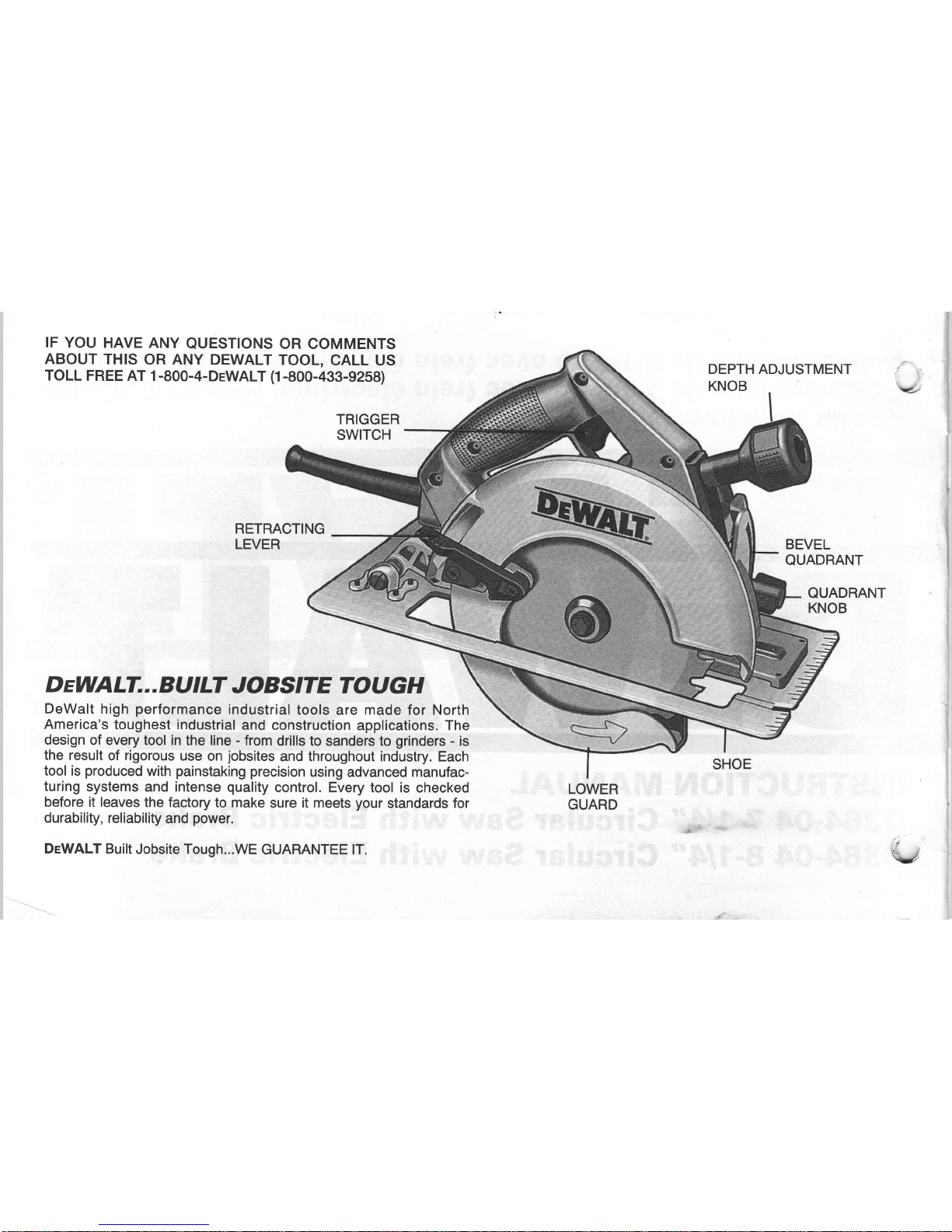
IF YOU
HAVE ANY
QUESTIONS OR COMMENTS
ABOUT
THIS
OR ANY DEWALT
TOOL,
CALL US
TOLL
FREE AT 1-800-4-DTWALT
(1-800-433-9258)
TRIGGER
SWITCH
RETRACTING
LEVER
D aWALT...
BU tLT
JO
BS7TE
TOU
cH
DeWalt high
performance
industrial
tools are made for North
America's
toughest
industrial
and construction
applications. The
design
of every tool in
the line - from
drills to
sanders
to
grinders
-
is
the result
of rigorous
use
on
jobsites
and throughout industry. Each
tool
is
produced
with
painstaking
precision
using advanced manufac-
turing
systems and intense
quality
control.
Every tool is
checked
before it leaves
the factory
to
make
sure it meets
your
standards for
durabiliÿ,
reliabiliÿ
and
power.
DeWALT
Built Jobsite Tough...WE
GUABANTEE lT.
DEPTH ADJUSTMENT
KNOB
BEVEL
QUADRANT
QUADRANT
KNOB
LOWER
GUARD
\U
Page 3

I
m
porta
nt S afeÿ
I nstru cti o
ns
*
WARNING:
When using Electric
Tools, basic safeÿ
precautions
should always
be followed
to reduce the
risk of fire, electric
shock and
personal
injury, including the
following:
*
Read all
lnstructions.
*
KEEP
WORK AREA CLEAN.
Cluttered areas
and benches invite
injuries.
*
CONSIDER
WORKAREA
ENVIRONMENT.
Don't expose
power
tools
to rain.
Don't use
power
tools
in damp or
wet locations.
Keep
work
area
well lit.
*
GUARD
AGAINST ELECTRIC SHOCK.
Prevent body
contact
with
grounded
sufaces.
For example:
pipes,
radiators,
ranges,
refrigerator
enclosures.
*
KEEP CHILDREN
AWAY. All visitors should
be kept away
from
work area.
Do not
let visitors contact tool or extension
cord.
*
STORE
IDLE TOOLS.
When not in use, tools should be stored
in dry,
and
high
or
locked-up
place -
out of
reach of children.
*
DON'T
FORCE
TOOL. lt will do the
job
better and
safer
at
the
rate for which
it was intended.
*
USE
RIGHT
TOOL. Don't
force
small tool or
attachment to do
the
job
of
a
heavy-duty
tool. Don't use tool for
purpose
not
intended, for example,
don't use circular saw
for cutting tree
limbs
or logs.
*
DRESS
PROPERLY.
Do not wear
loose
clothing or
jewelry.
They can be caught
in moving
parts.
Rubber
gloves
and
non-
skid footwear are
recommended
when working outdoors. Wear
protective
hair
covering
to contain
long hair.
*
USE
SAFETY
GLASSES.
Also
use
face or
dustmask
if opera-
tion
is dusÿ.
*
DON'T
ABUSE CORD.
Never carry
tool by cord
or
yank
it to dis-
connect
from receptacle.
Keep cord
from
heat, oil and
sharp
edges.
*
SECURE
WORK. Use
clamps or a
vise to
hold
work. lt's safer
than
using
your
hand and
it frees both
hands
to
operate
tool'
*
DON'T OVERREACH.
Keep
proper
footing
and balance
at all
times.
*
MAINTAIN
TOOLS
WITH CARE.
Keep tools
sharp and
clean
for
better
and safe
performance.
Follow instructions
for
lubricating
and
changing
accessories.
lnspect tool cords
periodically
and
if
damaged
have
repaired by authorized
service
faciliÿ.
lnspect
extension
cords
periodically
and replace
if damaged.
Keep
han:
dles dry,
clean and
free from
oil
and
grease.
*
DISCONNECT
TOOLS.
When not
in
use,
before
servicing
and
when changing
accessories,
such as
blades,
bits, cutters.
*
REMOVE
ADJUSTING
KEYS
AND WRENCHES.
FOTM
hAbit
Of
checking
to see that
keys and adiusting
wrenches are
removed
from tool
before turning
it
on.
*
AVOID UNINTENTIONAL
STARTING.
DON'I CArry
PIUggEd.iN
tool with
finger on switch.
Be sure switch
is off when
plugging
in.
*
OUTDOOR
USE
EXTENSION
CORDS.
When tool
is
used
out-
doors, use
only extension
cords
intended
for use outdoors
and
so
marked.
Page 4
lmporta
nt
Safeÿ
lnstructions
(Continued)
*
STAY ALERT.
Watch
what
you
are doing.
Use common
sense.
Do not
operate
tool when
you
are tired.
*
CHECK DAMAGED
PARTS.
Before
further
use of the
tool,
a
guard
or
other
part
that
is
damaged
should
be carefully
checked
to determine
that it
will
operate
properly
and
perform
ité
intended
function.
Check
for
alignment
of moving
parts,
binding
of moving
parts,
breakage
of
parts,
mounting
and any
other
coÀditions
thàt
Circular
Saw
Safeÿ
lnstructions
1. Disconnect plug
from
power
supply
before
changing
blades, mak-
ing
cutting
depth
or cutting
angle
adjustments,
inspecting,
clean-
ing
or when
saw is not
being used.
2. Keep
guards
in
place
and in working
order.
Never
wedge
or tie
lower
guard
open.
Check
operation
of
lower guard
before
each
use. Do
not
use if
lower
guard
does
not
close
briskly
and com-
pletely
over
saw
blades.
CAUTION:
lf
saw is
dropped, lower
guard
may
be
bent
restricting
full return.
Do
not
usè
saw until
_ loyel0yard
is
returned
to the
proper
working
order.
3.
KEEP
BI-ADES
CLEAN
AND
SHARP.
Shàrp
btades
minimize
stalling,
overload,
kickback
and
give
a cleaner
cut.
4. DANGER:
KEEP
HANDS
AWAY
FROM
CUTTING
AREA.
Keep
hands
away from
blades.
Do
not reach
underneath
work whilê
blade
is rotating.
Do
not
attempt
to remove
cut material
when
blade
is moving.
CAUTION:
Blades
continue
to
coast
after
releas-
ing trigger.
Never
place
your
hand
on
the work
surface
in front
of
or
behind
the saw.
manual.
Have
defective
switches
replaced
by
authorized
service
centre.
Do
not
use tool
if
switch
does not
turn
it
on and
off.
*
DO
NOT
OPERATE
portable
electric
tools near
flammable
liquids
or in
gaseous
or explosive
atmospheres.
Motors
in
these
iools
normally
spark
and the
sparks
might
ignite
fumes.
SAVE
THESE
INSTRUCTIONS
FOR
FUTURE
USE.
5.
SUPPORT
LARGE
PANELS.
Large
panels
must
be supported
as
shown
in FIGURE
14
to minimize
the
risk
of overload'
ând kick_
back
from
blade
pinching.
When
cutting
operation
requires
the
resting
of the
saw
on the
workpiece,
the
saw
should
be iested
on
the larger portion
and the
smaller
piece
cut
off.
6.
USE
RIP
FENCE.
Always
use
a fence
or straight
edge
guide
when
ripping.
7.
GUARD
AGAINST
K|CKBACK.
Kickback
occurs
when
the
saw
begins
to stall
rapidly
and is
driven
back
towards
the
operator.
Release
switch
immediately
if
blade
binds
or
saw
stallô.
Keep
blades
sharp.
Support
large
panels
as shown
in FIGURE
t+.
Usb
fence
or straight
edge
guide
when
ripping.
Don,t
force
tool.
Stay
alert,
exercise
control.
Don't
remove
saw-from
work
during
a
crit
while
the
blade
is moving.
A more
detailed
explanation
àt t<ick_
back
follows
the
"Operation"
section
of
this manual.
8. LOWER
GUARD.
When
necessary
for
accurate
starts
or
when
-
qgclelgyïIg,
laise
lower guard
wirh
the retracring
tever.
9.
ADJUSTMENTS.
Before
cutting
be sure
depth
aÀd bevet
adjust_
ments
are tight.
v
Page 5
10. USE
ONLY
BLADES
WITH
5/8"
DIAMETER
ARBOR. Do not
ft
use
blades
with incorrect size
holes. Never use defective or
'
incorrect blade washers or
bolts.
11.
AVOID
CUTTING
NAILS. lnspect for and
remove all
nails
from lumber before
cutting.
CAUTION:
When sawing
into walls, floors or
wherever
"live"
electrical
wires may be encountered,
DO
NOT TOUCH ANY
METAL PARTS OF
THE TOOL! Hold the Saw
only by its
plas-
tic
handles to
prevent
electric shock
if
you
saw into a
"live"
wire.
SAVE
THESE
INSTRUCTIONS
Motor
Your DeWalt
tool is
powered
by a DeWalt-built
motor.
Be
sure
your
power
supply
agrees
with nameplate
marking.
120 Volts
AC/DC means
your
saw
will
operate
on alternating
or direct cur-
rent. Lower
voltage
will
cause
loss of
power
and
can
result in
over-heating.
All DeWalt
tools
are
factory-tested;
if this tool does
not operate,
check
the
power
supply.
Double lnsulation
Your
unit
is DOUBLE
INSUI-ATED.
This means that
it is
con-
structed
throughout
with TWO separate
"layers"
of electrical
insu-
lation or one
DOUBLE thickness
of insulation between
you
and
the tool's electrical
system.
Tools
built
with this
insulation system are
not intended to be
grounded.
As a result,
your
tool
is equipped
with
a two-prong
plug
which
permits
you
to
use extension cords
without concern for
maintaining a
ground
connection.
NOTE: DOUBLE
INSULATION does
not take the
place
of
normal
safeÿ
precautions
when
operating
this tool.
This insulation sys-
tem is for
added
protection
againt
injury
resulting
from a
possible
,r{Bctrical
insulation failure within
the tool.
-
l,UTION:
When
servicing
all tools, USE ONLY
IDENTICAL
nEPIâCEMENT
PARTS. Repair or
replace damaged cords.
Electric
Brake
Your saw
has an automatic
electric brake
which is designed
to
stop
the blade
from
coasting
in
about
two seconds after
you
release
the trigger switch.
lt is
useful
when making certain
cuts
in
wood
where a coasting
blade
would result
in a
wide, imprecise
cut.
Occasionally,
under
certain
conditions,
the brake
will not function
properly
and
won't stop
the saw
in the 2 seconds
discussed
above.
lf this condition
persists,
turn the saw
on and off
four or
five times.
lf the brake still
does
not stop the blade
in about
2 sec-
onds,
the
problem
may be
worn brushes.
Replace the brushes as
described
below and
try
the saw again.
lf the
problem
still
per-
sists,
have the tool
seruiced at a
service
center or authorized
ser-
vice facility.
DeWalt tools are
serviced
by the
lndustrial
Tool
Division
of Black &
Decker
Canada
lnc.
Brushes
DISCONNECT
PLUG
FROM
POWER SUPPLY
lnspect
carbon brushes
regularly by
unplugging
tool,
removing
the'Brush
lnspection Cap
(Figure
2) and
withdrawing
the
brush
assembly.
Keep brushes
clean and
sliding
freely
in their
guides.
Always
replace a used
brush
in the same
orientation
in the
holder
as
it was
prior
to removal.
Carbon
brushes
have
varying symbols
stamped
into their sides, and
if
the
brushes
are
worn down to
the
line closest
to the spring,
they
must be
replaced. Use
only
identi-
cal
DeWalt brushes.
Always
replace
both brushes.
Use
of the
correct
grade
of
brush
is essential
for
proper
operation
of
electric
brakes.
New brush assemblies
are
available
at
your
local service
center.
The tool should
be allowed
to
"run
in"
(run
at
no load with-
out blade)
for 10
minutes before
use to
seat new brushes.
This is
especially
important
for saws equipped
with electric brakes,
which
may
be
erratic
in operation
until the brushes
are
properly
seated
(worn
in).
While
"running
in"
DO NOT
TlE,
TAPE, OR OTHERWISE
LOCK
THE TRIGGER SWITCH
ON.
HOLD
BY HAND ONLY.
Page 6

Adjustments
and
Setup
ATTACHING
AND REMOVING
BLADES
DISCONNECT
PLUG FROM
POWER
SUPPLY.
To attach
the blade, retract
lower
blade
guard
and
place
inner
clamp
washer
and blade on
saw spindle with
printed
side
of blade
out
(teeth
at bottom
ol blade
pointing
forward)
(Figure
1). lnstall
outer clamp washer.
The larger
sufaces of
both washers must
face the
blade. Thread
on blade clamping
screw firmly
by
hand
to
hold
washers in
position.
Lightly
depress
the blade lock
(Figure
2) while
turning the
spindle
until the blade stops
rotating. Tighten
blade
clamping
screw
(clockwise)
firmly with
the blade wrench
(Figure
3).
NEVER ENGAGE
BLADE
LOCK WHILE
SAW IS RUNNING,
OR
ENGAGE IN
AN EFFORT
TO STOP THE
TOOL. NEVER
TURN
SWITCH
ON
WHEN
BLADE LOCK
IS ENGAGED.
When removing
the
blade, first
unplug the
saw.
Engage
the blade
lock
and unscrew the blade
clamping
screw by turning it
counter-
clockwise with the
blade wrench.
CUTTING DEPTH ADJUSTMENT
DISCONNECT
PLUG FROM POWER
SUPPLY.
Loosen
(counterclockwise)
the Cutting
Depth Adjustment
Knob,
shown in
(Figure
4).
Lift the
saw handle,
as shown in the figure,
to
adjust
it
to the desired height.
Tighten
the knob
to secure it in
place.
lf depth
of cut cannot
be adjusted, inspect
parts
for
dam-
age
and service as required
before
use. A scale
and
pointer
is
provided
to
enable
you
to
select a specific
depth of cut.
Simply
align the
pointer,
shown in
(Figure
5), to
the desired depth
of cut.
FIG.1
INNER
CLAMP
WASHER
OUTER
CLAMP
WASHER
BLADE
CLAMPING
SCREW
LOOSEN
Y.'
BRUSH INSPECTION
CAP
Page 7

->
PO|NTER
SCALE
NOTE: To adjust the depth of cut
pointer
for various
blade diame-
ters,
loosen
the Cutting
Depth Adjustment Knob
and
raise the
saw
until the blade
just
touches the workpiece and tighten
the
knob.
This is
the
zero
depth of cut
position.
lf required, loosen the
screw
that holds the
pointer
and
adjust
to the
zero indicator mark.
The saw is now
adjusted
to
accurately
indicate the depth of cut
for the blade used.
For the most efficient cutting
action
using a carbide tipped saw
blade, set the Depth Adjustment so that about one half of a tooth
projects
below the surface of the
wood
to be cut.
The height
of a
whole tooth is the distance from the tip of the tooth to the boüom
of the
gullet
in
front of
it.
Study
Figures
5A and 58
to
determine
what
one
half tooth means.
(5A
shows
one half tooth
projecting
below
the surface
and
figure
58
shows a whole tooth
projecting
below the sufface).
Setting the saw
at the
proper
cutting depth
keeps
blade
friction
to
a
minimum, removes sawdust from between the blade teeth,
results in cooler, faster sawing and reduces the chance
of kick-
back.
A
method of checking for the correct cutting depth
is
shown in
Figure 6. Lay a
piece
of the
material
you plan
to
cut along
the
side of the blade, as shown
in
the figure, and observe
how much
tooth
projects
beyond
the material.
NOTE: When
using a
non carbide tipped blade, make an excep-
tion to the above
procedure
and allow a
full tooth to
project
below
the
material,
as shown
in Figure
58.
BEVEL ANGLE ADJUSTMENT
DISCONNECT THE
SAW
FROM THE POWER
SUPPLY.
The full range of the Bevel Adjustment is from
0
to 50 DEGREES.
ïhe
quadrant
is
graduated
in increments of 1 degree.
On the
front
of the saw
is
a bevel angle adjustment
mechanism
(Figure
8) consisting of a calibrated
quadrant
and a
knob. To
set
the saw
for
a bevel cut,
loosen
(counterclockwise)
the
quadrant
knob
and
tilt
shoe
to the
desired angle by aligning
the
pointer
with
the desired angle
mark. Retighten knob firmly
(clockwise).
FIG.5A
RIP FENCE
FIG.58
Page 8

KERF INDICATOR
The front
of
the
saw shoe
has
a
kerf indicator
(Figure
8)
for verti-
cal and bevel cutting.
This indicator
enables
you
to
guide
the saw
along
cutting lines
penciled
on the
material
being cut.
The indica-
tor
lines
up with the left
(inner)
side of
the
saw blade,
which
makes
the slot or
"kef'
cut by the moving
blade
fall to the right of
the
indicator.
Guide along the
penciled
cutting line so that
the kerf
falls
into
the waste or
surplus
material
-
See
Figure
9.
Figure 9
shows the dimensions of the shoe. Note
that
the left side is 5
1/2"
between the lefi side
of
the
blade and the
left
edge
of the shoe
(standard
6x lumber). The right
dimension
is 1 112"
(standard
2x
lumber).
SHOE
ALIGNMENT
Your saw has
been set at the factory
for
accurate
vertical
cuts
(a
90 degree angle between the bottom of the shoe and
the blade).
The edge of the
shoe
has
also
been
set
parallel
to the blade
so
that it will not bind when using an edge
guide,
lf
the saw should
ever need adjustment, it may be done as follows:
ADJUSTING FOR
90" CUTS
1. DISCONNECT PLUG FROM POWER
SUPPLY.
2. Adjust the saw to 0" bevel.
3.
Place saw on blade
side
(Figure
10). Retract
blade
guard.
4. Loosen
quadrant
knob.
(Figure
10). Place
a
square against
the blade
and
shoe to
adjust the
g0'
setting.
5. Loosen the
hex nut
and move the
adjustment
screw so that
the shoe
will
stop at the
proper
angle
as shown
in Figure 11.
Lock the screw in
place
by tightening the hex nut.
6.
lt may
be
necessary
to
adjust
the
quadrant
angle
pointer
to
line up on
"O"
after shoe has been
adjusted.
Yk
FIG.9
GUIDE
ALONG WASTE
PENCILED CUTTING OR
LINE
SO
KERF FALLS SURPLUS
IN WASTE STOCK STOCK
Allrn
btt side
ot
Atign
E{t
sidê
ôfr.
saw blade with
"+5'
sEw blade wilh
mark,
as shofln,
{or
',0"
mark for
45c kr€l eutùr!g
.'r::
§treiâlil
cuitinû.
OUADRANT
u
Page 9

HEX NUT
ADJUSTING THE
SHOE
PRALLEL TO THE BLADE
1. DISCONNECT
PLUG FROM POWER
SUPPLY.
2. Loosen the hex nut shown in
(Figure
12) and then
turn the
adjustment
screw in or out
as
needed to adjust for
parallelism.
3.
Adjust the
shoe
until it is
parallel
to the blade by
measuring
from the edge of the shoe to the blade, front & rear.
You
can
measure from the outside edge of the blade to the shoe as
shown in
(Figure
12) or from the
inner
edge of the blade to the
wider
part
of
the shoe.
(Do
not measure from the tips of
any
saw blade
teeth.)
4. When the shoe and blade are
parallel,
hold the
adjusting
screw
in
place
and
tighten the hex nut firmly.
Operation
SWITCH
Pull the trigger switch to turn the
motor
"ON".
Releasing the trig-
ger
turns
the motor.OFF".
Releasing the trigger
also automatical-
ly
actuates
the electric brake.
This tool has no
provision
to lock
the switch
in
the
"ON" position,
and
should never be
locked
"ON"
by any other
means.
WORKPIECE SUPPORT
Figure 13 shows
proper
sawing
position.
Note
that
hands
are
kept away from cutting area, and
power
cord
is
positioned
clear
of the cutting area so that
it will not
get
caught or hung up on the
work.
To
avoid
kickback, DO support
board
of
panel
NEAR the cut
and
on both sides of the cut,
(Figure
14). DON'T support board or
panel
away
from the
cut,
(Figure
15). When ripping long narrow
strips,
support cut-otf waste material.
When operating the saw, keep the cord
away
from the cutting
area and
prevent
it
from becoming
hung
up on the
workpiece.
Note that
a special Cord
Keeper has
been
provided
on
the
tool's
handle,
as shown
in Figure 4.
Simply
press
the cord
into
the
keeper
to
keep it in
sight and out of the
way.
QUADRANT HEX
POINTER
NUT
SCREW
FtG. 12
FtG. 13
Page 10

WARNING:
lt is important
to support the work
properly
and to hold
the saw firmly
to
prevent
loss
of control which
could cause
personal
injury; Figure 13
illustrates
ÿpical
hand
support of the saw.
ALWAYS
DISCONNECT
SAW
BEFORE
MAKING ANY ADJUST-
MENTS!
Place the work
with its
"good"
side
-
the
one on
which
appearance is most important
-
down. The
saw cuts upward,
so any
splintering will
be on the work face
that is up when
you
saw
it.
Support the work
so that the cut will
be on
your
right. Place the wider
portion
of the saw shoe
on that
part
of the workpiece which
is solidly
supported,
not on the
section that will fall
off
when
the cut is made. As
examples, Figure
16 illustrates
the RIGHT way
to cut off the end of a
board,
and Figure 17 the
WRONG way. Always
clamp work. Don't try
to hold
short
pieces
by hand!
Remember to
support cantilevered and
overhanging material.
Use caution when sawing material
from below.
CUTTING
Be
sure saw is up to
full speed before
blade contacts material to be
cut.
Starting saw with
blade against material to
be
cut
or
pushed
for-
ward into kerf
can result in kickback.
Push
the
saw
forward
at
a
speed which
allows the blade
to cut
with-
out laboring. Hardness
and toughness
can vary even in the same
piece
of material,
and knotty or
damp sections can
put
a
heavy load
on
the saw. When
this happens,
push
the saw more slowly, but hard
enough
to keep it working without
much
decrease
in
speed.
Forcing
the
saw can cause rough
cuts, inaccuracy, kickback
and over-heating
of the motor.
Should
your
cut begin to
go
off the line,
don't try to force it back on.
Release
the
switch and
allow blade to come to
a complete stop.
Then
you
can withdraw
the saw,
sight anew,
and start a
new
cut slightly
inside
the
wrong
one. ln
any event, withdraw
the saw
if
you
must
shift
the
cut.
Forcing
a
correction
inside
the cut can stall the saw and
lead
to kickback. lF
SAW STALLS, RELEASE THE TRIGGER
AND BACK
THE
SAW
UNTIL
IT IS LOOSE.
BE
SURE
BI.ADE IS
STRAIGHT
IN
THE
CUT AND
CLEAR
OF
THE
CUTTING EDGE BEFORE
RESTARTING.
FtG.
15
WRONG
MATERIAL
BENDS
ON
BLADE
CAUSING HEAVY
LOADS
OR KICKBACK.
SUPPORT
WORK
NEAR
CUT
WRONG
Page 11

rl§s
you
finish a
cut, release
the trigger and
allow
the blade
to stop
ftfore
lifting the saw
from the
work.
As
you
lift
the saw, the
spring-tensioned
telescoping
guard
will
automatically
close under
the blade.
Remember the
blade
is exposed until
this
occurs,
never reach under
the
work for any
reason
whatsoever.
When
you
have to
retract the
telescoping
guard
manually
(as
is neces-
sary for starting
pocket
cuts) always
use
the retracting
lever.
NOTE: When cutting
thin strips,
be
careful to ensure
that small
cutoff
pieces
don't
hang up
on
inside of
lower
guard.
Always use a
fence or
straight
edge
guide
when
ripping'
POCKET
CUTTING
DISCONNECT
PLUG
FROM POWER
SUPPLY.
Adjust
saw
shoe
so blade
cuts at
desired depth.
Tilt
saw
forward
and
rest front of
the shoe on
material
to be cut.
Using
the
retracting
lever, relract
blade
guard
to an
upward
position.
Lower rear
of shoe until
blade
teeth almost
touch
cutting
line. Now
release the
blade
guard
and
its
contact
with the
work will
keep it in
position
to open
freely as
you
startthe
cut
(Figure
18).
Start
the
motor
and
gradually
lower
the saw
until
its shoe
rests
flat on
the
material
to be
cut.
Advance
saw along
the
cutting
line
until
cut
is completed.
Release trigger
and
allow
blade
to stop
completely
before
withdrawing
the
blade
from the
material'
When
starting
eàch
new
cut, repeat
as above.
Never tie
the blade
guard
in a
raised
position.
Kickback
When the
saw
blade becomes
pinched
or
twisted
in the
cut,
kick-
back
can
occur.
The
saw is thrust
rapidly
back
toward
the
opera-
tor.
When
the blade
is
pinched
or
bound
tightly
by the
kerf
closing
down,
the
blade
stalls
and the
motor
reaction
drives
the unit
backward.
When
the
blade becomes
twisted
or misaligned
in the
cut,
the
teeth at
the
back edge
of
the blade
can
dig
into the
top
surface
of
the
wood
causing
the blade
to climb
out
of
the
kerf and
jump
back
toward
the
oPerator.
kictiOack
is
more
likely to
occur
when any
of the
following
condi-
tions
exist.
1. IMPROPER
WORKPIECE
SUPPORT
A. Sagging
or
improper
litting of
the cut
off
piece
causing
pinching
of
the blade.
B. ôutting
through
material
supported
at
the
outer
ends
only
(see
Figure
15).
As the
material
weakens
it
sags,
closing
down
the
kerf and
pinching
the blade.
C.
Cutting
of
a cantilevered
or
overhanging
piece
oJ
material
from the
bottom
up
in a vertical
direction.
The falling
cut off
piece
can
pinch
the
blade.
D. Ôutting
off long
narrow
strips
(as
in
ripping).
The cut
off
strip
can sag
or twist
closing
the
kerf and
pinching
the
blade.
E. Snagging
the
lower
guard
on a surface
below
the
material
being
cut
momentarily
reducing operator
control'
The saw
can
lift
partially
out
of the
cut
increasing
the
chance
of
blade
twist.
Page 12

2. IMPROPER
DEPTH
OF CUT
SETTING
ON
SAW
Using the
saw with
an
excessive
depth
cut setting
increases
loading
on
the unit
and susceptibility
to
twisting
of the blade in
the kerf.
lt
also increases
the
surface
area of the
blade avail-
able for
pinching
under
conditions
of kerf close
down.
3. B|-ADE
TWIST|NG
(M|SALIGNMENT
tN
CUT)
A. Pushing
harder
to
cut through
a
knot,
nail,
or a hard
grain
area
can cause
the
blade to twist.
B. Trying
to turn
the
saw in the
cut
(trying
to
get
back
on the
marked
line)
can cause
blade
twist.
C. Extended
reach
or
operating
saw with
poor
body
control
(out
of
balance),
can result
in
twisting
the
blade.
D.
Changing
hand
grip
or body
position
white
cutting
can
result
in
blade
twist.
E. Backing
unit up to
clear
blade
can lead
to twist if not
done
carefully.
4.
MATERIALS
THAT
REQUIRE
EXTRA
ATTENTION
A. Wet
lumber
B.
Green lumber
(materialfreshly
cut
or not kiln
dried)
C. Pressure
treated
lumber
(material
treated with
preserva-
tives
or anti-rot
chemicals)
5.
USE OF DULL
OR DIRTY
BI.ADES
Dull
or dirÿ blades
cause increased
loading
of the
saw, To
compensate,
an operator
will
usually
push
harder
which
fur-
ther loads
the
unit
and
promotes
twisting
of the
blade in
the
kerf.
Worn
blades
may
also
have
reduced
body
clearance
which
increases
the chance
of
binding
and increased
loading.
6. LIFTING
THE
SAW WHEN
MAKING
BEVEL
CUTS
Bevel_
cuts
require
special
operator
attention
to
proper
cutting
techniques -
especially
guidance
of the
saw. Both
blade
anglé
to the
shoe
and
greater
blade
surface in
the material
increale
the chance
for
binding
and misalignment (twist)
to
occur.
7.
RESTARTING
A
CUT
WITH THE
BLADE
TEETH
JAMMED."
AGAINSTTHE
MATERIAL
I
The
saw
should
be
brought
up to full
operating
speed
beforèÿ
starting
a cut
or
restarting
a cut
after the
unit has
been
stopped
with
the blade
in
the kerf. Failure
to do
so can
cause
stalling
and kickback.
Any
other
conditions
which
could result
in
pinching,
binding,
twisÈ
ing,
or misalignment
of
the blade
could
cause kickback.
Èefer
to
the
sections
on
'Adjustments
And
SetUp"
and
"Operation',
for
procedures
and
techniques
that will
minimize
the occurrence
of
kickback.
Blades
A
dull blade
will
cause
slow, inefficient
cutting
overload
on the
saw motor,
excessive
splintering
and could increase
the
possibili-
ÿ
of kickback.
lt is
a
good practice
to keep
extra
blades'on
hand
so that
sharp
blades
are
available while
the dull ones
are
being
sharpened
(See "SAWS-SHARPEN|NG"
in
the
ye[ow pages).
tn
fact,
many
lower
priced
blades
can
be replaced
with new
ônes
at
very
little
cost
over the
sharpening
price.
Hardened
gum
on the
blade
will
slow down
the cutting.
This
gum
can best
be removed
with
kerosene,
turpentine
or
oven cleanôr.
DeWalt
manufactures
a complete
line
of saw
blades
and the fol-
lowing
ÿpes
of blades
are available
from
your
service
center.
VISUALLY
EXAMINE
CARBIDE
BLADES
BEFORE
USE.
REPLACE
IF DAMAGED.
10
\,
Page 13

FLADETYPE
COMBINATION
-
For
general purpose
ripping and
cutting
CROSS-CUT
-
For smoother,
faster
cross cutting
RIPPING
-
For fast rip cuts
PLYWOOD
-
For smooth
cuts in
plywood.
Reduce splintering.
FRAMING/RIP
-
For facing,
roofing, siding, sub-flooring,
fram-
ing, form cutting.
PLANER
-
For
very smooth ripping and
cross-cutting.
FRICTION
-
For cutting
corrugated,
galvanized
sheets.
METAL-CUTTING
-
For cutting aluminum,
copper
and other
soft
metals.
FLOORING
-
For sawing
where
nails may be occasionally
encountered.
CARBIDE-TIPPED
-
For longest sawing
without blade sharp-
ening.
Cuts
wood,
Transite, Cemesto
board,
Formica,
Masonite, and
similar
materials.
Accessories
lf
you
need assistance
in locating any accessory,
please
contact:
DeWALT
lndustrial
Tool
ComPanY
Consumer
Service
DePartment
100 CentralAve.
P.O. Box 618
Brockville,
Ont.
K6V 5W6
Every
DeWalt tool
is of
the
highest
quality.
A.
RIP
FENCE...
Attaches
to top of Saw
shoe.
Permits
rip cuts
without
penciled
guide
line.
B. SAW
PhOTRACTOR...
Guides
Saw
for accurate
cut-off
work.
Adjusts
from 0
to
70
degrees.
C.
CUT-OFF
GUIDE...
For 90
degree or
45 degree
cuts.
D. CARRYING
CASE...
Protects
your
Saw.
Keeps
blades'
extension
cords,
etc.
handy on
the
job.
E. SAFETY
SPECTACLES...
Designed to
fit over
standard
glasses.
F. FILTER
MASK
CAUTION:
Recommended
accessories
and
saw blades
for
your
Saw are
listed
in this manual.
The
use of any
other
accessory
or
attachment
may be
hazardous.
The
accessories
listed in this
manual are available
at eltra cost.
.A
complete
listinq of
service centres
is included on the depot
list-
ft
."ro
packed
üith
your
tool.
1't
Page 14

Extension
Cords
Double-insulated
tools have
2-wire
cords and
can be
used with 2-
wire
or 3-wire
extension
cords.
Only round-jacketed
extension
cords should
be used. lf
the extension
will
be used
outside, the
cord must
be suitable for
outdoor
use. Any
cord marked
as out-
door
can be used for
indoor work.
The letter
"W'on
the cord
jack-
et
indicates
that the cord is
suitable for
outdoor
use.
An
extension cord
must have
adequate
wire
size
(AWG
or
American
Wire
Gauge) for
safety,
and to
prevent
loss
of
power
and overheating.
The
smaller the
gauge
number
of
the
wire,
the
greater
the capacity
of the cable,
that is 16
gauge
has more
capacity
than
18
gauge.
When using
more
than one extension
to
make
up
the total length,
be sure
each individual
extension
con-
tains
at
least
the minimum
wire
size.
To determine
the minimum
wire
size
required,
refer
to the
chart
below.
oHART FOR MTN|MUM
WIRE
S|ZE
(AWG)
OF
EXTENSION
CORDS
NAMEPLATE
TOTALEXTENSIONCORDLENGTH-METRES
RATTNG-AMPS
10 15
20
30 40 45
50 60
0-10.0
10.1-13.0
13.1-15.0
Before
using
an extension
cord, inspect
it for
loose
or exposed
wires,
damaged insulation,
and defective
fittings. Make
any need-
ed repairs
or replace
the cord if
necessary.
lmpohant!
To
assure
product
SAFETY
and RELIABILITY,
particutarty
for
Double-lnsulated
tools, repairs,
maintenance
and adjustment
(excluding
maintenance
described in
this manual)
should
be
per-
formed
by BLACK
& DECKER
Service
Centres
or other
qualified
service
organizations,
always using
the identical
DEWALT
replacement
parts.
ONE.YEAR
WARRANTY
DeWalt
Heavy
Duÿ Tools
are warranted
for
one
year
from
datei"-
purchases
to
correct
by repair
or
parts
replâcement
withoLÉ
ghargq,
any
product
defect
due
to faulÿ
material
or workmanship
for
tools used
in
commercial
or rental
sérvice. Arrangements
havb
been
made
with
the lndustrial
Tool
Division
of Blàck & Decker
Canada Inc.
to
provide
warranÿ
repairs
for
DeWalt
Tools.
piTply.
retqrn
the complele
unit'transportation prepaid
to
any
lndustrial
Black
& Decker
Service
Centè
or
lndudtriai
Authorizeâ
Service
Centre. DeWalt
assumes
no responsibility
for
damage
or
faulÿ
performance
caused
by misuse,
careless hàndling
or rihere
repairs
have
been made,
or attempted
by others.
No ôther
war-
ranties,
written
or verbal,
are authorized.
Note:
This
warranÿ
and
related
provisions
set
out above
may not
be
applicable in
certain
provinces.
30 DAY NO
RISK
SATISFACTION
GUARANTEE
II
y9y.rl"
not
completely
satisfied
with
the
performance
of
your
DeWalt
heavy
duÿ industrial
tool,
simply return
the
complete irnit,
including
all accessory
items,
to
the
pariicipating
seller
dr direcfly,
transportation
prepaid,
to:
DeWalt
lndustrial
Tool
Company,
100
Central Avenue,
Brockville,
Ontario
K6V 5W6
Attention:
Satisfaction
Guarantee
Department
Proof
of
purchase
is required
to receive
your
refund.
DEWALT
INDUSTRIAL
TOOL
COMPANY,
1OO
CENTRAL
AVE.
BROCKVILLE,
ONTARIO
K6V
5W6
16
16 16
16
14 14 12
12
16
16 14
14 14
12 12
12
14
14
12 12
12 12
12
v
Printed in
U.S.A.
Form
263582-01
(JULeS-CD-2)
 Loading...