

Page 1

D28410-XE
D28411-XE
D28414-XE
D28432C-XE
1
Page 2
2
3
1
A
2
4
5
Copyright DEWALT
Page 3
4
7
9
6
10
11
8
B
C2
10
14
12
13
11
3
C1
14
12
10
11
A
14
12
10
11
B
C3
3
Page 4
15
19
17 16
D1
15
18
5
17
5
D2
E1
4
E2
Page 5

ANGLE GRINDER
D28410/D28411/D28414/D28432C
ENGLISH
Congratulations!
You have chosen a DEWALT tool. Years of
experience, thorough product development and
innovation make D
partners for professional power tool users.
E
WALT one of the most reliable
Technical data
D28410 D28411
Voltage V 230 230
Power input W 2,100 2,100
No-load speed min
Wheel diameter mm 180 230
Spindle M14 M14
Weight kg 4.7 4.7
D28414 D28432C
Voltage V 230 230
Power input W 2,200 2,600
No-load speed min
Wheel diameter mm 230 230
Spindle M14 M14
Weight kg 4.7 5.3
Fuses:
Europe 230 V tools 10 Amperes, mains
U.K. & Ireland 230 V tools 13 Amperes, in plugs
The following symbols are used throughout this
manual:
-1
8,500 6,500
-1
6,500 6,500
EC-Declaration of conformity
D28410/D28411/D28414/D28432C
DEWALT declares that these power tools have been
designed in compliance with: 98/37/EC,
89/336/EEC, 2006/95/EC, EN 60745-1,
EN 50144-2-3, EN 55014-2, EN 55014-1,
EN 61000-3-2 & EN 61000-3-3.
For more information, please contact DEWALT at the
address below, or refer to the back of the manual.
Level of sound pressure according to 86/188/EEC &
98/37/EC, measured according to EN 50144:
D28410 D28411 D28414 D28432C
(sound pressure) dB(A)* 90.5 90.0 90.0 90.0
L
pA
(acoustic power) dB(A) 99.5 98.5 98.5 98.5
L
WA
* at the operator’s ear
Take appropriate measures for the
protection of hearing.
Weighted root mean square acceleration value
according to EN 50144:
Denotes risk of personal injury, loss of
life or damage to the tool in case of
non-observance of the instructions in this
manual.
Denotes risk of electric shock.
Fire hazard.
D28410 D28411 D28414 D28432C
5.8 m/s
2
5.95 m/s2 5.9 m/s2 5.9 m/s
Director Engineering and Product Development
Horst Großmann
DEWALT, Richard-Klinger-Straße 40,
D-65510, Idstein, Germany
04/2007
2
5
Page 6

ENGLISH
Safety instructions
When using power tools, always observe the
safety regulations applicable in your country
to reduce the risk of fi re, electric shock and
personal injury.
Read all of this manual carefully before operating
the tool.
Save this manual for future reference.
General
1 Keep work area clean
Cluttered areas and benches can cause accidents.
2 Consider work area environment
Do not expose the tool to rain. Do not use the tool
in damp or wet conditions. Keep the work area
well lit (250 - 300 Lux). Do not use the tool where
there is a risk of causing fi re or explosion, e.g. in
the presence of fl ammable liquids and gases.
3 Keep children away
Do not allow children, visitors or animals to come
near the work area or to touch the tool or the
mains cable.
4 Dress properly
Do not wear loose clothing or jewellery, as these
can be caught in moving parts. Wear protective
hair covering to keep long hair out of the way.
When working outdoors, preferably wear suitable
gloves and non-slip footwear.
5 Personal protection
Always use safety glasses. Use a face or dust
mask whenever the operations may produce
dust or fl ying particles. If these particles might
be considerably hot, also wear a heat-resistant
apron. Wear ear protection at all times.
6 Guard against electric shock
Prevent body contact with earthed surfaces
(e.g. pipes, radiators, cookers and refrigerators).
When using the tool under extreme conditions
(e.g. high humidity, when metal swarf is being
produced, etc.), electric safety can be improved
by inserting an isolating transformer or a (FI)
earth-leakage circuit-breaker.
7 Do not overreach
Keep proper footing and balance at all times.
8 Stay alert
Watch what you are doing. Use common sense.
Do not operate the tool when you are tired.
9 Secure workpiece
Use clamps or a vice to hold the workpiece. It is
safer and it frees both hands to operate the tool.
10 Connect dust extraction equipment
If devices are provided for the connection of dust
extraction and collection facilities, ensure that
these are connected and properly used.
11 Remove adjusting keys and wrenches
Always check that adjusting keys and wrenches
are removed from the tool before operating
the tool.
12 Extension cables
Before use, inspect the extension cable and
replace if damaged. When using the tool
outdoors, only use extension cables intended for
outdoor use and marked accordingly.
13 Use appropriate tool
The intended use is described in this instruction
manual. Do not force small tools or attachments
to do the job of a heavy-duty tool. The tool will
do the job better and safer at the rate for which it
was intended. Do not force the tool.
Warning! The use of any accessory or
attachment or performance of any operation
with this tool other than those recommended
in this instruction manual may present a risk of
personalinjury.
14 Check for damaged parts
Before use, carefully check the tool and mains
cable for damage. Check for misalignment and
seizure of moving parts, breakage of parts,
damage to guards and switches and any other
conditions that may affect its operation. Ensure
that the tool will operate properly and perform
its intended function. Do not use the tool if any
part is damaged or defective. Do not use the tool
if the switch does not turn it on and off. Have
any damaged or defective parts replaced by an
authorised D
EWALT repair agent. Never attempt
any repairs yourself.
15 Unplug tool
Switch off and wait for the tool to come to a
complete standstill before leaving it unattended.
Unplug the tool when not in use, before
changing any parts of the tools, accessories or
attachments and before servicing.
6
Page 7

ENGLISH
16 Avoid unintentional starting
Do not carry the tool with a fi nger on the switch.
Be sure that the tool is switched off before
plugging in.
17 Do not abuse cord
Never carry the tool by its cord. Never pull the
cord to disconnect from the socket. Keep the
cord away from heat, oil and sharp edges.
18 Store idle tools
When not in use, tools must be stored in a dry place
and locked up securely, out of reach of children.
19 Maintain tools with care
Keep the tools in good condition and clean
for better and safer performance. Follow the
instructions for maintenance and changing
accessories. Keep all handles and switches dry,
clean and free from oil and grease.
20 Repairs
This tool is in accordance with the relevant
safety regulations. Have your tool repaired by an
authorised DEWALT repair agent. Repairs should
only be carried out by qualifi ed persons using
original spare parts; otherwise this may result in
considerable danger to the user.
Additional safety instructions for Australia
andNew Zealand
• This tool is not intended for use by young
children or infi rm persons without supervision.
Young children should be supervised to ensure
they do not play with this tool.
• If the supply cord is damaged, it must be
replaced by the manufacturer or an authorised
DEWALT Service Centre in order to avoid a
hazard.
Additional safety rules for grinders
• Your grinder has been designed for grinding and
cutting masonry and steel.
Do not cut or grind light metal with a
magnesium content exceeding 80%
since this type of metal is fl ammable.
in Figure A. Contravention may lead to loss of
control and unexpected injuries.
• The max. allowable speed of the grinding wheel
or cutting disc must always be equal to or greater
than the no-load speed of the tool specifi ed on
the nameplate.
• Do not cut workpieces requiring a maximum
depth of cut exceeding that of the cutting disc.
• Do not use grinding and cutting discs that do not
conform to the dimensions stated in the technical
data. Do not use any spacers to make a disc fi t
onto the spindle.
• Inspect grinding and cutting discs before each
use. Do not use chipped, cracked or otherwise
defective discs.
• If provided, ensure that blotters are used when
the disc is fi tted onto the spindle.
• Ensure that the grinding or cutting disc is
mounted correctly before use.
• Let the tool run at no-load in a safe position for
at least 30 seconds. If there is a considerable
vibration or if any other defect occurs, stop the
tool and check it to determine the cause.
• Do not operate this tool without the guard in place.
• Check that the workpiece is properly supported.
• Do not operate the tool near fl ammable liquids,
gases or dust. Sparks or hot chips from cutting
or arcing motor brushes may ignite combustible
materials.
• Do not operate the tool while standing in line with
the disc. Keep other persons away from the work
area.
• Do not use cutting discs for side grinding.
• Do not operate the spindle lock while the tool is
running.
• Beware that after switching off the tool the wheel
continues to rotate for a short period.
• Always store grinding and cutting discs in a dry
place.
Labels on tool
The following pictographs are shown on the tool:
• Only reinforced cutting-off and reinforced
depressed-centre grinding wheels are allowed.
• Use the grinding and cutting discs recommended
by the manufacturer only.
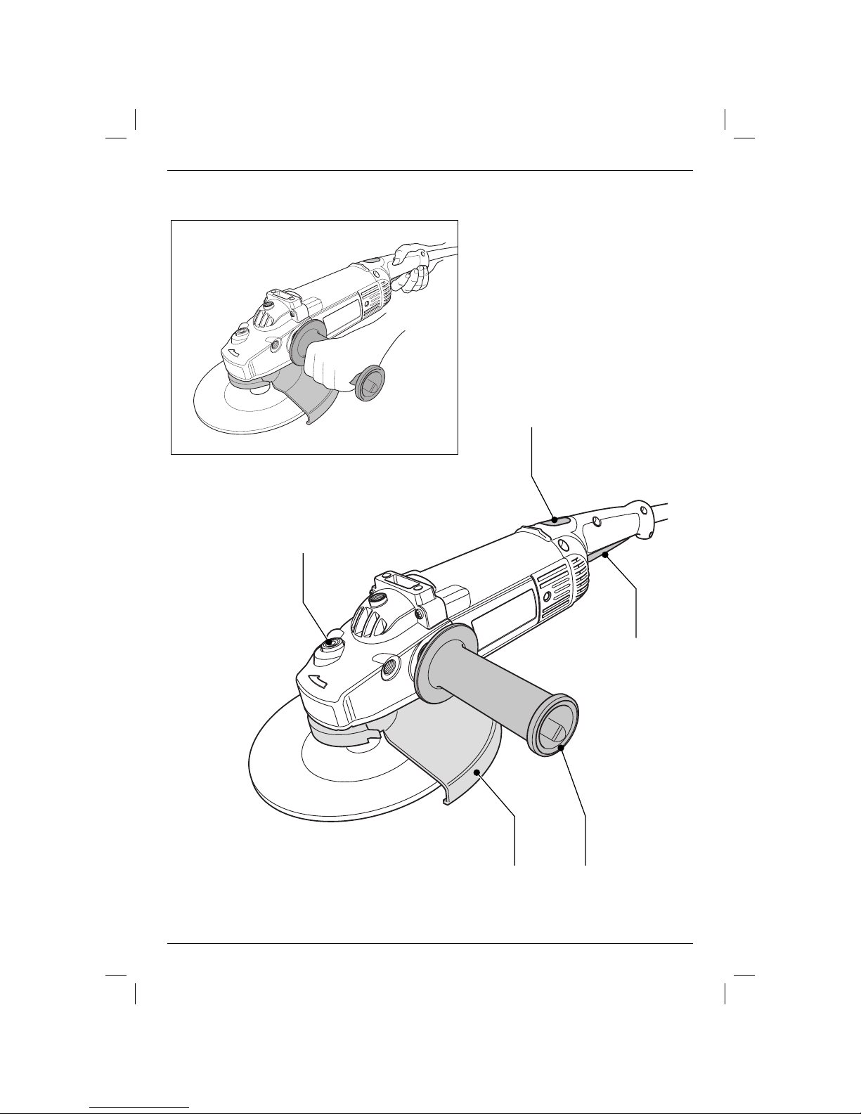
• To ensure your personal safety it is compulsory
to hold the machine with both hands as shown
Read the instruction manual before use
Wear safety glasses
7
Page 8

ENGLISH
Wear ear protection
Package contents
The package contains:
1 Angle grinder
1 Guard
1 Side handle
1 Flange set
1 Two-pin spanner
1 Instruction manual
1 Exploded drawing
• Check for damage to the tool, parts or accessories
which may have occurred during transport.
• Take the time to thoroughly read and understand
this manual prior to operation.
Description (fi g. A)
Your angle grinder has been designed for
professional grinding and cutting applications.
1 On/off switch
2 Locking switch/Unlocking switch (France,
Australia and New Zealand)
3 Spindle lock
4 Guard
5 Side handle
• Disconnect the plug from the supply.
• Cut off the plug and dispose of it safely; a plug
with bared copper conductors is dangerous if
engaged in a live socket outlet.
• Only fi t 13 Amperes BS1363A approved plugs
fi tted with the correctly rated fuse (1).
• The cable wire colours, or a letter, will be marked
at the connection points of most good quality
plugs. Attach the wires to their respective points
in the plug (see below). Brown is for Live (L) (2)
and Blue is for Neutral (N) (4).
• Before replacing the top cover of the mains plug
ensure that the cable restraint (3) is holding the
outer sheath of the cable fi rmly and that the two
leads are correctly fi xed at the terminal screws.
Never use a light socket.
Never connect the live (L) or neutral (N)
wires to the earth pin marked E or .
D28414/D28432C - Soft start feature
The soft start feature allows a slow speed build-up
to avoid an initial jerk when starting. This feature is
particularly useful when working in confi ned spaces.
Electrical safety
The electric motor has been designed for one
voltage only. Always check that the power supply
corresponds to the voltage on the rating plate.
Your DEWALT tool is double insulated in
accordance with EN 50144; therefore no
earth wire is required.
Mains plug replacement
(U.K. & Ireland only)
• Should your mains plug need replacing and you
are competent to do this, proceed as instructed
below. If you are in doubt, contact an authorized
DEWALT repair agent or a qualifi ed electrician.
8
Fitting a mains plug to 115 V units
(U.K. & Ireland only)
• The plug should be fi tted by a competent
person. If you are in doubt, contact an authorized
D
EWALT repair agent or a qualifi ed electrician.
The wires are coloured according to the following
code:
live = brown
neutral = blue
• Do not connect the blue or brown wire to the
earth terminal in the plug. Connect as follows:
brown to terminal marked ‘L’
blue to terminal marked ‘N’
The plug fi tted should be comply with BS EN 60309
(BS4343), 32 Amps.
Page 9

ENGLISH
Always ensure that the cable clamp is
correctly and securely fi tted to the sheath
of the cable.
Using an extension cable
If an extension cable is required, use an approved
extension cable suitable for the power input of this
tool (see technical data). The minimum conductor
size is 1.5 mm
2
.
When using a cable reel, always unwind the cable
completely.
Also refer to the following table.
Conductor size (mm2) Cable rating (Amperes)
0.75 6
1.00 10
1.50 15
2.50 20
4.00 25
Cable length (m)
7.5 15 25 30 45 60
Voltage Amperes Cable rating (Amperes)
115 0 - 2.0 6 6 6 6 6 10
2.1 - 3.4 6 6 6 6 15 15
3.5 - 5.0 6 6 10 15 20 20
5.1 - 7.0 10 10 15 20 20 25
7.1 - 12.0 15 15 20 25 25 -
12.1 - 20.0 20 20 25 - - 230 0 - 2.0 6 6 6 6 6 6
2.1 - 3.4 6 6 6 6 6 6
3.5 - 5.0 6 6 6 6 10 15
5.1 - 7.0 10 10 10 10 15 15
7.1 - 12.0 15 15 15 15 20 20
12.1 - 20.0 20 20 20 20 25 -
Assembly and adjustment
Prior to assembly and adjustment always
unplug the tool.
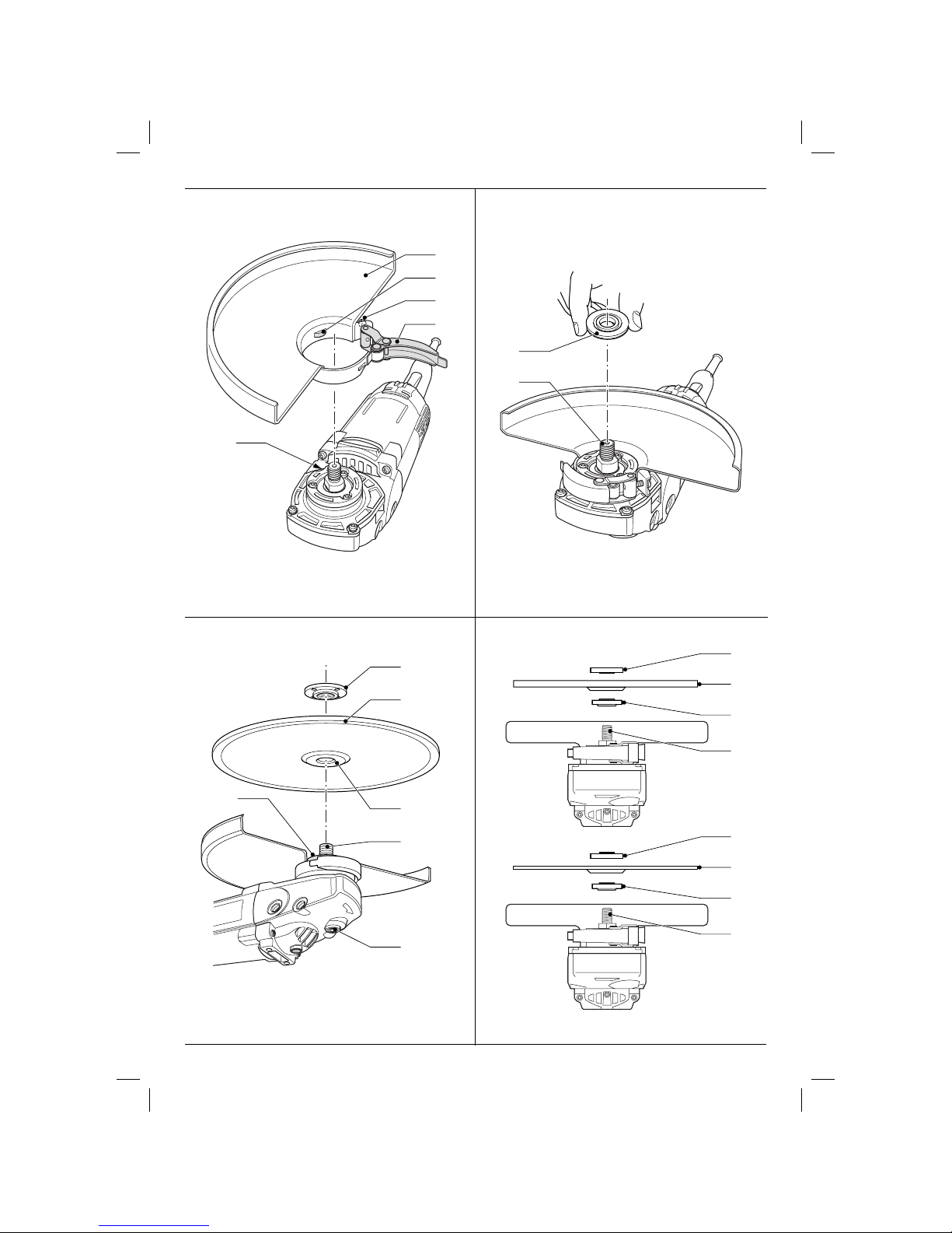
Mounting and removing the guard (fi g. B)
• Place the angle grinder on a table, spindle up.
• Release the clamping lock (6) and hold the guard
(4) over the tool as shown.
• Align the lugs (7) with the notches (8).
• Press the guard down and rotate it to the
required posiiton.
• If required, increase the clamping force by
tightening the screw (9).
• Tighten the clamping lock.
• To remove the guard, release the clamping lock.
Never use the tool without the guard in
place.
Fitting and removing a grinding or cutting disc
(fi g. C1 - C3)
• Place the tool on a table, guard up.
• Fit the inner fl ange (10) correctly onto the spindle
(11) (fi g. C1).
• Place the disc (12) on the fl ange (10) (fi g. C2).
When fi tting a disc with a raised center, make
sure that the raised centre (13) is facing the
fl ange (10).
• Screw the outer fl ange (14) onto the spindle (11)
(fi g. C3):
- the ring on the fl ange (14) must face towards
the disc when fi tting a grinding disc (A);
- the ring on the fl ange (14) must face away from
the disc when fi tting a cutting disc (B).
• Press the spindle lock (3) and rotate the spindle
(11) until it locks in position (fi g. C2)
• Tighten the fl ange (14) with the two-pin spanner
supplied.
• Release the spindle lock.
• To remove the disc, loosen the fl ange (14) with
the two-pin spanner.
Do not use a damaged disc.
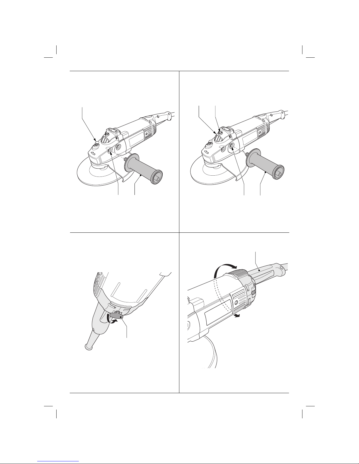
Mounting the side handle (fi g. D1 & D2)
• For grinding, screw the side handle (5) tightly into
one of the holes (15) on either side of the gear
case (fi g. D1).
• For cutting, screw the side handle (5) tightly into
the top hole (16) or into one of the holes (17) on
either side of the gear case (fi g. D2).
D28432C - Rotating the main handle (fi g. E1 & E2)
The rotary handle facilitates a more comfortable
handling in cutting applications with the side handle
mounted in the top hole.
The rotary handle has locations at 30°, 60° and 90°
both left and right.
9
Page 10

ENGLISH
• Pull the spring-loaded tab (18) to unlock the
rotary mechanism (fi g. E1). Hold the tab in the
pulled-out position.
• Rotate the handle (19) into the desired position
(fi g. E2).
• Release the tab and lock it in position.
• Check that the rotary mechanism is locked.
Do not use the tool unless the rotary
handle is in the locked postion.
Instructions for use
• Always observe the safety instructions
and applicable regulations.
• Ensure all materials to be ground or cut
are secured in place.
• Apply only a gentle pressure to the tool.
Do not exert side pressure on the disc.
• Avoid overloading. Should the tool
become hot, let it run a few minutes
under no load condition.
Prior to operation:
• Install the guard and appropriate disc or wheel.
Do not use excessively worn discs or wheels.
• Be sure the inner and outer fl ange are mounted
correctly.
• Make sure the disc or wheel rotates in the direction
of the arrows on the accessory and the tool.
Do not switch the tool on or off when
under load.
Consult your dealer for further information on the
appropriate accessories.
Maintenance
Your D EWALT Power Tool has been designed to
operate over a long period of time with a minimum
of maintenance. Continuous satisfactory operation
depends upon proper tool care and regular cleaning.
Lubrication
Your power tool requires no additional lubrication.
Cleaning
Keep the ventilation slots clear and regularly clean
the housing with a soft cloth.
Unwanted tools and the environment
Take your tool to an authorized DEWALT repair agent
where it will be disposed of in an environmentally
safe way.
DEWALT AFTER SALES SERVICE
Switching on and off (fi g. A)
The on/off switch is equipped with an unlocking
switch or a locking switch for continuous operation.
On/off switch (1) with locking switch (2)
• To run the tool, depress the locking switch (2)
and subsequently operate the on/off switch (1).
• Release the locking switch (2).
• To stop the tool, press the on/off switch again.
On/off switch (1) with unlocking switch (2)
(France, Australia and New Zealand)
• To run the tool, depress the unlocking switch (2)
and subsequently operate the on/off switch (1).
• Release the unlocking switch (2).
• To stop the tool, release the switch.
10
REPAIR AND SERVICE
All DEWALT power tools are thoroughly tested
before leaving the factory. However, if the power
tool needs repair, please contact your dealer or
take it to your nearest D
There is a Service Centre in every capital city.
For service, repair or parts call 1800 654 155
(Aust) or 02 259 1111 (NZ).
EWALT Service Centre.
Page 11

GUARANTEE
ENGLISH
THREE YEAR LIMITED WARRANTY
DEWALT will repair, without charge, any defects
due to faulty materials or workmanship for three
years from the date of purchase. Please return
the complete unit, transportation prepaid, to any
D
EWALT Service Centre, or any authorised service
station. For warranty repair information, call (AUS)
1800 654 155 or (NZ) 02 259 1111. This warranty
does not apply to:
• Accessories.
• Damage caused where repairs have
beenmade or attempted by others.
• Damage due to misuse, neglect, wear and
tear, alteration or modifi cation.
This warranty gives you specifi c legal rights and
you may have other rights under the provisions
of the Consumer Guarantee Act 1993 (New
Zealand only), Trade Practices Act 1974 and State
Legislation (Australia only).
In addition to the warranty, D
EWALT tools are
covered by our:
FREE ONE YEAR SERVICE CONTRACT
DEWALT will also maintain the tool for free at
anytime during the fi rst year of purchase. This
includes labour, parts and lubrication required to
restore the product to sound mechanical and/or
electrical condition. Normal wear parts are not
covered in this service. Carbon brushes worn
more than 50% will be replaced.
INFORMATION HOTLINE
When you need further information on a D
EWALT
product please phone:
Australia: 1800 816 900
New Zealand: 09 579 7600
NOTES
EWALT reserves the right to change or
• D
upgrade product specifi cations or standard
equipment at any time without notice.
• Standard equipment and accessories may vary
by country.
• Product specifi cations may vary by country.
• Complete product range may not be available
in all countries. See your local DEWALT dealer
for range availability.
NOTE: 3 Year warranty is not applicable to items
deemed as consumables. Radial arm saws are
covered by a one (1) year warranty only. DEWALT
reserves the right to review its warranty policy
prior to launch of any new business development
products.
30 DAY NO RISK SATISFACTION GUARANTEE
If you are dissatisfi ed with any DEWALT power tool,
laser or nailer, for any reason, simply return it to
the point of purchase with your sales receipt within
30 days for a replacement unit or a full refund.
11
Page 12

Australia Black & Decker (Australia) Pty. Ltd. Tel: 03 8720 5100
20 Fletcher Road Fax: 03 9727 5940
Mooroolbark, Victoria 3138
New Zealand Black & Decker Tel: 02 259 1111
81 Hugo Johnston Drive Fax: 09 579 8200
Penrose, Auckland, New Zealand
653602-00 5/07
 Loading...