

Page 1
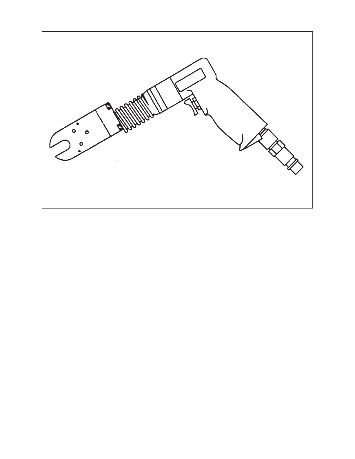
TABLE OF CONTENTS
CUSTOMER MESSAGE Inside Front Cover
SAFETY PRECAUTIONS 3
92-0116 Rev. 060810
Model 550 Tube Severing Tool
GENERAL DESCRIPTION 6
SPECIFICATIONS 7
MAINTENANCE 9
OPERATION 10
REPAIRS AND REPLACEMENT 13
AIR DRIVE ASSEMBLY 15
TROUBLE SHOOTING 16
ACCESSORIES 18
ILLUSTRATED PARTS BREAKDOWN 19
DEWALT SAFETY INSTRUCTIONS 43
TOOL BIT RESHARPENING POLICY Inside Back Cover
WARRANTY INFORMATION Inside Back Cover
Page 2

Copyright 2006
Proprietary property of TRI TOOL Inc.
No reproduction, use, or duplication of the information
shown hereon is permitted without the express written
consent of TRI TOOL Inc.
Page 3

SAFETY PRECAUTIONS
IN GENERAL
When using rotating head cutting equipment, basic safety precautions should always
be followed to reduce the risk of personal injury.
Operate this tool only in accordance with specific operating instructions.
Do not override the deadman switch on the power unit. Locking down, ob-
WARNING:
DRESS CONSIDERATIONS
structing, or in any way defeating the deadman switch on the power drive unit
may result in serious injury.
Model 550 Tube Severing Tool
Use standard safety equipment. Hard hats, safety shoes, safety harnesses, protective clothes, and other safety devices should always be used when appropriate.
Use safety glasses. Do not operate cutting tools without eye protection.
Dress properly. Do not wear loose clothing or jewelry. They can be caught in rotating and moving parts. Avoid slippery floors or wear nonskid footwear. If you have
long hair, wear protective hair covering to contain it.
WORK AREA
Keep the work area clean. Cluttered work areas and benches invite injuries.
Consider the work area environment. Keep the area well lit. Keep electrical cords,
cables, rags, rigging straps, and etc. clear of rotating equipment. Do not use powercutting tools in the presence of flammable liquids and gasses.
Keep visitors away. Do not let visitors or untrained personnel at or near operating
tools. Enforce eye protection requirements for all observers.
Do not over reach. Keep proper footing at all times.
Stay alert. Watch what you are doing. Use common sense. Do not operate tools
when you are tired.
92-0116 : Rev. 060810
3
Page 4

TRI TOOL INC.
TOOL CARE
Maintain tools with care. Keep tools in good operating condition. Sharp tool bits
perform better and safer than dull tool bits. Well maintained tools function properly
when needed.
Check for damaged parts. If a tool has malfunctioned, been dropped or hit, it must
be checked for damage. Run no-load tests and feed function checks. Do a complete visual inspection.
Electric motors. Use only with proper AC voltage power sources and observe all
normal electric shock hazard procedures.
Do not abuse power and control cords. Pulling or running over cords and cables
can result in electrical shock hazards and malfunctions. Keep control and power
cords out of all cutting fluids and water.
Hydraulic drives. Observe proper procedures for electrically driven power sources.
Avoid damage to hydraulic lines. Keep quick-disconnects clean. Grit contamination
causes malfunctions.
Air tools. Check the exhaust muffler. Broken or damaged mufflers can restrict air
flow or cause excessive noise. Use air motors only with a filtered, lubricated and
regulated air supply. Dirty air, low-pressure air or over pressure air will cause malfunctions, including delayed starting.
AREA EQUIPMENT
Secure work. Whenever possible use clamps, vises, chains and straps to secure
pipe.
Make sure the tool is secured; it is safer to have both hands free to operate the tool.
TOOL USE
Use the right tool and tool bit for the job. Do not use a tool, which is incorrect for the
job you are doing.
Keep the tool bits fully engaged in the tool bit holders. Loose bits are a safety hazard.
4
92-0116 : Rev. 060810
Page 5

Model 550 Tube Severing Tool
Disconnect power supply during setup and maintenance. Use all ‘Stop’ or Shut off’
features available when changing or adjusting tool bits, maintaining the tool, or when
the tool is not in use.
Remove adjusting keys and wrenches before applying power to the equipment.
Develop a habit of checking the tool before turning it on to make sure that all keys
and wrenches have been removed.
Do not force tools. Tools and tool bits function better and safer when used at the
feed and speed rate for which they were designed.
Do not reach into rotating equipment. Do not reach into the rotating head stock to
clear chips, to make adjustments, or to check surface finish. A machine designed to
cut steel will not stop for a hand or an arm.
Handle chips with care. Chips have very sharp edges and are hot. Do not try to pull
chips apart with are hands; they are very tough.
Avoid unintentional starts. Do not carry or handle tools with your hand on the operating switches or levers. Do not lay the tool down in a manner that will start the
drive. Do not allow the tool to flip around or move when adjusting or changing tool
bits.
Store idle tools properly. Disconnect tools from the power source and store in a safe
place. Remove tool bits for safe handling of the tool.
92-0116 : Rev. 060810
5
Page 6

TRI TOOL INC.
GENERAL DESCRIPTION
The Model 550 Tube Severing Tool series of tube cutters is designed to cut tubing in
areas where access to and around the tube is limited.
The Model 550 uses a cutter wheel to sever the tube. Normal operation will not
produce chips.
The Model 550 is powered by Tri Tool Inc. pneumatic, electrical or manual Drive
Units.
The Model 550 features an automatic feed, which permits an even pressure on the
cutting wheel during operation.
6
92-0116 : Rev. 060810
Page 7
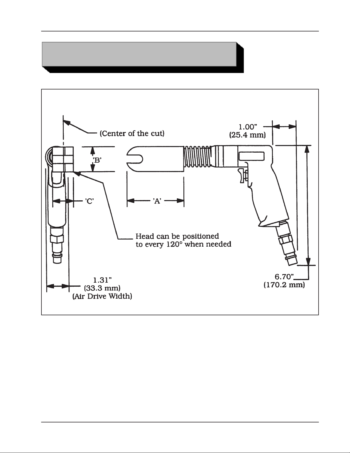
SPECIFICATIONS
Envelope, Model 550-00, Tube Severing Tool
Model 550 Tube Severing Tool
92-0116 : Rev. 060810
7
Page 8

TRI TOOL INC.
(
)
(
)
(
)
(
)
(
g)
(
)
(
)
(
)
(
)
(
g)
(
)
(
)
(
)
(
)
(
g)
(
)
(
)
(
)
(
)
(
g)
(
)
(
)
(
)
(
)
(
g)
(
)
(
)
(
)
(
)
(
g)
(
)
(
)
(
)
(
)
(
g)
(
)
(
)
(
)
(
)
(
g)
(
)
(
)
(
)
(
)
(
g)
(
)
(
)
(
)
(
)
(
g)
(
)
(
)
(
)
(
)
(
g)
(
)
(
)
(
)
(
)
(
g)
(
)
(
)
(
)
(
)
(
g)
(
)
(
)
(
)
(
)
(
g)
Envelope, Model 550-00, Tube Severing Tool
Model
P/N
No.
550-03 01-1062
550-04 01-1063
550-05 01-1064
550-06 01-1009
550-08 01-1065
550-10 01-1066
550-12 01-1067
550-14 01-1075
550-16 01-1068
550-18 01-1069
550-20 01-1070
Tube
Size
3/16"
4.8 mm
1/4"
6.4 mm
5/16"
7.9 mm
3/8"
9.5 mm
1/2"
12.7 mm
5/8"
15.9 mm
3/4"
19.1 mm
7/8"
22.2 mm
1"
25.4 mm
1 1/8"
28.6 mm
1 1/4"
31.8 mm
"A" "B" "C" Weight
3.67"
93.2 mm
3.67"
93.2 mm
3.67"
93.2 mm
3.67"
93.2 mm
4.36"
110.7 mm
4.53"
115.1 mm
4.63"
117.6 mm
4.88"
124.0 mm
5.02"
127.5 mm
5.88"
149.4 mm
6.13"
155.6 mm
1.50"
38.8 mm
1.50"
38.8 mm
1.50"
38.8 mm
1.50"
38.8 mm
2.25"
57.2 mm
2.38"
60.5 mm
2.50"
63.5 mm
2.63"
66.8 mm
2.75"
69.9 mm
3.13"
79.5 mm
3.38"
85.9 mm
1.25"
31.8 mm
1.25"
31.8 mm
1.25"
31.8 mm
1.25"
31.8 mm
1.53"
38.9 mm
1.53"
38.9 mm
1.53"
38.9 mm
1.53"
38.9 mm
1.53"
38.9 mm
1.53"
38.9 mm
1.56"
39.6 mm
2.25 lb
1.02 k
2.47 lb
1.12 k
2.65 lb
1.20 k
2.94 lb
1.33 k
3.16 lb
1.43 k
4.22 lb
1.91 k
4.85 lb
2.20 k
.75 lb
.34 k
.75 lb
.34 k
.75 lb
.34 k
.75 lb
.34 k
550-24 01-1071
550-28 01-1072
550-32 01-1073
8
1 1/2"
38.1 mm
1 3/4"
44.5 mm
2"
50.8 mm
7.10"
180.3 mm
7.70"
195.6 mm
8.19"
208.0 mm
4.00"
101.6 mm
4.38"
111.3 mm
4.75"
120.7 mm
1.56"
39.6 mm
1.56"
39.6 mm
1.56"
39.6 mm
6.64 lb
3.01 k
7.87 lb
3.57 k
9.10 lb
4.13 k
92-0116 : Rev. 060810
Page 9

Model 550 Tube Severing Tool
MAINTENANCE
All components should be periodically cleaned and coated with a light film of oil.
Use a clean, non-detergent oil, preferably SAE 10 (90 SSU or lighter.)
The Cutting Wheel should be replaced if worn or damaged.
The Cutting Wheel life depends upon the tube material, wall thickness, and
operator’s experience.
Short and long bearing plugs should be replaced when worn, damaged or scratches
occur on the tube being cut.
92-0116 : Rev. 060810
9
Page 10
TRI TOOL INC.
OPERATION
Read the operating instructions carefully before attempting to operate the Model 550
Tube Severing Tool.
Be sure to use eye protection at all times when operating the Model 550.
Select the proper Model 550 for the size of tubing to be severed.
Maximum Tube Wall Thickness
Model
No.
550-03 3/16" (4.8 mm) .065" (1.6 mm) .065" (1.6 mm) .065" (1.6 mm)
550-04 1/4" (6.4 mm)
550-05 5/16" (7.9 mm)
550-06 3/8" (9.5 mm)
550-08 1/2" (12.7 mm) .095" (2.4 mm) .100" (2.5 mm) .100" (2.5 mm)
550-10 5/8" (15.9 mm) .125" (3.2 mm)
550-12 3/4" (19.1 mm) .095" (2.4 mm)
550-14 7/8" (22.2 mm) .125" (3.2 mm)
550-16 1" (25.4 mm) .095" (2.4 mm)
550-18 1 1/8" (28.6 mm) .125" (3.2 mm)
550-20 1 1/4" (31.8 mm) .100" (2.5 mm)
550-24 1 1/2" (38.1 mm) .110" (2.8 mm)
550-28 1 3/4" (44.5 mm) .125" (3.2 mm)
Tube
Size
Aluminum
Stainless
Steel
Titanium
550-32 2" (50.8 mm)
Be sure the Cutter Wheel of the Tube Severing Tool you have selected is sharp,
rotates freely and is not damaged in any way.
A damaged or non-rotating Cutter Wheel can affect the performance of the tool.
Be sure Bearing Plugs are clean and not damaged.
Damaged Bearing Plugs affect the performance of the tool and should be changed.
10
92-0116 : Rev. 060810
Page 11
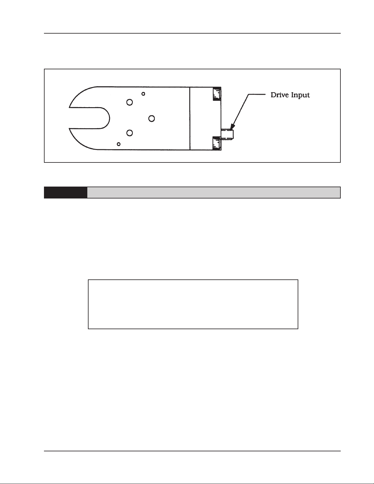
Select the proper Tri Tool Inc. Drive Unit that best suits the operation needed to be
performed.
Drive Input Location
A non Tri Tool Inc. Drive Unit will void the warranty.
Model 550 Tube Severing Tool
NOTE:
CONNECTING AND DISCONNECTING THE DRIVE SYSTEM TO THE MODEL 550
The entire series of Model 550 Tube Cutters are equipped with a quick disconnect
drive-mounting system.
The drive units, which are equipped with a mating quick disconnect, are universal,
they will operate with any Model 550 size that is selected.
If input is counterclockwise, sever damage will occur during cutting.
! WARNING !
Disconnect the Drive Unit from its power source
when installing or removing it from the Model 550
Tub Cutter otherwise serious injury may occur.
To connect an air or electric drive unit, simply align the slots of the drive system to
the pin located inside the Model 550 coupling, push the drive system inward and
rotate counterclockwise and release.
The drive unit is equipped with a spring to allow it to lock securely.
The drive unit should now be locked in place.
Align the slot.
The rotation direction of the input must be clockwise.
92-0116 : Rev. 060810
11
Page 12

TRI TOOL INC.
Rotate drive shaft in a clockwise direction to align the slot.
If you miss alignment, simply realign the slot.
Load the Model 550 around the tube to be cut.
Apply a light force to insure that the Model 550 is over the tube.
The Model 550 must be held perpendicular to the surface of the tube to be cut.
Turn on the power for the Model 550 and begin the tube sever.
After the tube has severed, continue rotation, observing the cutting wheels until they
have returned to the home position.
Turn the power off.
Remove the Model 550 from the tube.
12
92-0116 : Rev. 060810
Page 13
Model 550 Tube Severing Tool
REPAIRS AND REPLACEMENT
WARNING:
Rotate the drive shaft manually clockwise to rotate the cutter carriage to the desired
position.
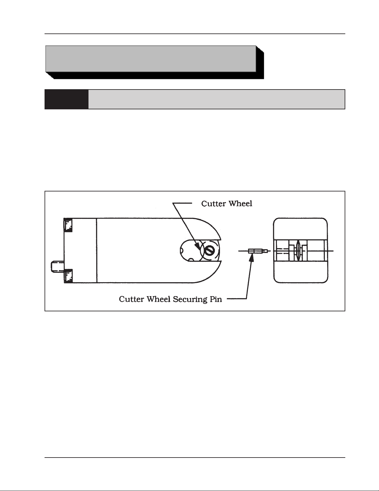
REPLACEMENT OF THE CUTTER WHEEL
Rotate the Cutter Carriage Assy until you see the Cutting Wheel and the cutter
Wheel Securing Pin access hole.
Cutter Wheel Replacement
Disconnect the Drive Unit from the Model 550 Tube Cutter prior to any repairs
or replacements.
Take a small screwdriver and a pair of needle nose pliers to remove the Wheel
Securing Pin.
Insert a pair of needle nose pliers and take hold of the edge of the Cutter Wheel and
remove it from the Model 550 Tube Cutter.
Take the new Cutter Wheel and install it by reversing the removal procedure.
REPLACEMENT OF THE BEARING PLUGS
Rotate the Cutter Carriage Assy until the Bearing Plug that is to be replaced can be
seen.
Press out the worn Bearing Plug.
92-0116 : Rev. 060810
13
Page 14

TRI TOOL INC.
Press in the new Bearing Plug.
Refer to the Illustrated Parts Breakdown for the correct Bearing Plug.
Bearing Plug Replacement
14
92-0116 : Rev. 060810
Page 15

Model 550 Tube Severing Tool
AIR DRIVE ASSEMBLY
REMOVAL OF A SHEARED ROLL PIN FROM THE DRIVE ASSY.
Push the Air Drive Assy into the Model 550 Tube Cutter and rotate it clockwise and
pull it out.
Unscrew the Bayonet Mounting Tube from the Motor Housing by rotating the
Bayonet Mounting Tube counterclockwise.
Take a punch and gently remove the remaining parts of the Roll Pin from the Drive
Shaft and the Motor Shaft.
ASSEMBLY OF THE DRIVE ASSY.
Press Roll Pin partly into one side of hole in Drive Shaft being careful not to protrude
into inside diameter.
Position Drive Shaft onto the Motor Shaft and press Roll Pin into the Shafts.
Recess the Roll Pin slightly below the surface of the outside diameter of the Drive
Shaft using a punch.
Pin Placement
Slide the Bayonet Mounting Tube over the Drive Shaft and screw the Bayonet
Mounting Tube onto the Motor Housing by rotating clockwise.
92-0116 : Rev. 060810
15
Page 16

TRI TOOL INC.
TROUBLE SHOOTING
Problem: The Tool Bit Chatters
Probable causes:
The tool bit is loose or overextended.
The tool bit is damaged.
The tool holder is too loose in the slides.
The cutting speed is too fast.
The clamping pads are loose on the pipe or tube.
Cutting fluid is required.
The main bearing pre-load is loose.
Problem: There is excessive Tool Bit wear
Probable causes:
The pipe or tube material is too hard or abrasive.
The cutting speed is too fast.
Cutting fluid is required.
A dull Tool Bit is causing surface hardening conditions (Stainless pipe or
tubing).
There is scale or other foreign matter on the pipe or tube, which is dulling the
tool bit at the start of the cut.
The tool bit is incorrect for the material being cut.
Problem: The surface finish is rough
Probable causes:
The tool bit is dull, chipped, etc.
Metal build-up on the cutting edge of the tool bit is creating a false cutting
edge.
Cutting fluid is required.
16
92-0116 : Rev. 060810
Page 17

Problem: The tool holder is not feeding
Probable causes:
The feed pin is broken or out of position.
The feed sprocket shear pin is broken.
The feed screw is stripped.
The feed nut is stripped.
The slide rails are too tight.
Problem: There is a loss of air power
Probable causes:
The air supply pressure is too low.
The air filter is plugged.
The air line size is insufficient.
The air line is too long.
Model 550 Tube Severing Tool
Problem: There is a loss of hydraulic power
Probable causes:
The hydraulic supply pressure is too low.
The hydraulic filter is plugged.
The hydraulic line size is insufficient.
The hydraulic line is too long.
Problem: The tool bit will not reach the work
Probable causes:
Incorrect tool blocks are installed for the size of the pipe or tube being worked
on.
Incorrect tool bit is installed.
Problem: The hydraulic motor will not start
Probable causes:
The hydraulic power supply is shut off.
The hydraulic motor is damaged and will not run free.
92-0116 : Rev. 060810
17
Page 18

TRI TOOL INC.
The following accessories are recommended for use with the Model 550 Tube Cutters and are available from TRI TOOL INC.
1. Portable Air Filter (P/N 75-0115)
2. Drive Assembly, Air (P/N 04-0084)
3. Shaft Assembly, 18” Flexible (P/N 14-0036)
4. Motor Assembly, Cordless, 14.4V (P/N 58-0213)
A Filter/Regulator/Lubricator (FRL) is required to protect the warranty on all TRI
TOOL INC air driven tools.
ACCESSORIES
18
92-0116 : Rev. 060810
Page 19

Model 550 Tube Severing Tool
ILLUSTRATED PARTS BREAKDOWN
MODEL 550-03, 04, 05, AND 06
TUBE SEVERING TOOL ASSEMBLY (P/N 01-XXXX)
19
16
14
6
20
21
15
23
26
12
24
9
4
2
10
1
4
8
5
13
11
3
7
92-0116 : Rev. 060810
18
10
9
22
17
25
19
Page 20

TRI TOOL INC.
Parts List, Model 550-03, Tube Cutter (P/N 01-1062)
Item Part
No. No. Description Qty
02-2057 CARRIAGE ASSEMBLY, CUTTER 1
1. 19-0353 HOUSING, CARRIAGE, TUBE CUTTER 1
2. 32-0003 PIN, ROLL, 1/16" DIA X 1/2" 1
3. 32-0179 PIN, DOWEL, 3/16" DIA X 5/8" 1
4. 32-0226 PIN, DOWEL, 3/16" DIA X 1" LONG 2
5. 32-0251 PIN, CUTTER 1
6. 38-0065 SPROCKET ASSEMBLY, FEED 1
7. 39-0382 GEAR, CARRIAGE, 12DP, 29T, 1.21PD 1
8. 40-0139 SPRING, TORSION 1
9. 54-0270 PLUG, SHORT, BEARING 2
10. 54-0271 PLUG, LONG, BEARING 2
11. 61-0017 WHEEL, CUTTER, 1/2" 1
12. 62-0066 CAM ASSEMBLY, AUTOFEED 1
13. 63-0081 ARM, CUTTER 1
14. 19-0355 HOUSING, MAIN 1
15. 24-0518 PLATE, RETAINING 1
16. 32-0172 PIN, TRIPPER, 3/32" 2
17. 32-0179 PIN, DOWEL, 3/16" DIA X 5/8" 2
18. 32-0272 PIN, DOWEL, 3/16" X 1 1/4" 1
19. 33-0017 SCREW, CAP, #6-32 X 1" 3
20. 33-0024 SCREW, CAP, #8-32 X 1" 3
21. 33-0927 SCREW, SET, 1/4-20 X 1/2", HDOG 1
22. 39-0289 GEAR, PINION 2
23. 39-0295 GEAR ASSEMBLY, WORM 1
24. 39-0335 GEAR, DRIVE, 24DP, 30T, .96PD 1
25. 43-0274 COVER, MAIN HOUSING 1
26. 45-0112 BUSHING,BRONZE, FL, 3/16" X 5/16" X 1/4" 1
20
92-0116 : Rev. 060810
Page 21

Model 550 Tube Severing Tool
Parts List, Model 550-04, Tube Cutter (P/N 01-1063)
Item Part
No. No. Description Qty
02-2058 CARRIAGE ASSEMBLY, CUTTER 1
1. 19-0354 HOUSING, CARRIAGE, TUBE CUTTER 1
2. 32-0003 PIN, ROLL, 1/16" DIA X 1/2" 1
3. 32-0179 PIN, DOWEL, 3/16" DIA X 5/8" 1
4. 32-0226 PIN, DOWEL, 3/16" DIA X 1" LONG 2
5. 32-0251 PIN, CUTTER 1
6. 38-0065 SPROCKET ASSEMBLY, FEED 1
7. 39-0381 GEAR, CARRIAGE, 12DP, 29T, 1.21PD 1
8. 40-0139 SPRING, TORSION 1
9. 54-0270 PLUG, SHORT, BEARING 2
10. 54-0271 PLUG, LONG, BEARING 2
11. 61-0017 WHEEL, CUTTER, 1/2 1
12. 62-0066 CAM ASSEMBLY, AUTOFEED 1
13. 63-0081 ARM, CUTTER 1
14. 19-0438 HOUSING, MAIN 1
15. 24-0518 PLATE, RETAINING 1
16. 32-0172 PIN, TRIPPER, 3/32" 2
17. 32-0179 PIN, DOWEL, 3/16" DIA X 5/8" 2
18. 32-0272 PIN, DOWEL, 3/16" X 1 1/4" 1
19. 33-0017 SCREW, CAP, #6-32 X 1" 3
20. 33-0024 SCREW, CAP, #8-32 X 1" 3
21. 33-0927 SCREW, SET, 1/4-20 X 1/2", HDOG 1
22. 39-0289 GEAR, PINION 2
23. 39-0295 GEAR ASSEMBLY, WORM 1
24. 39-0335 GEAR, DRIVE, 24DP, 30T, .96PD 1
25. 43-0274 COVER, MAIN HOUSING 1
26. 45-0112 BUSHING,BRONZE, FL, 3/16" X 5/16" X 1/4" 1
92-0116 : Rev. 060810
21
Page 22

TRI TOOL INC.
Parts List, Model 550-05, Tube Cutter (P/N 01-1064)
Item Part
No. No. Description Qty
02-2059 CARRIAGE ASSEMBLY, CUTTER 1
1. 19-0356 HOUSING, CARRIAGE, TUBE CUTTER 1
2. 32-0003 PIN, ROLL, 1/16" DIA X 1/2" 1
3. 32-0179 PIN, DOWEL, 3/16" DIA X 5/8" 1
4. 32-0226 PIN, DOWEL, 3/16" DIA X 1" LONG 2
5. 32-0251 PIN, CUTTER 1
6. 38-0065 SPROCKET ASSEMBLY, FEED 1
7. 39-0380 GEAR, CARRIAGE, 12DP, 29T, 1.21PD 1
8. 40-0139 SPRING, TORSION 1
9. 54-0270 PLUG, SHORT, BEARING 2
10. 54-0271 PLUG, LONG, BEARING 2
11. 61-0017 WHEEL, CUTTER, 1/2" 1
12. 62-0066 CAM ASSEMBLY, AUTOFEED 1
13. 63-0081 ARM, CUTTER 1
14. 19-0439 HOUSING, MAIN 1
15. 24-0518 PLATE, RETAINING 1
16. 32-0172 PIN, TRIPPER, 3/32" 2
17. 32-0179 PIN, DOWEL, 3/16" DIA X 5/8" 2
18. 32-0272 PIN, DOWEL, 3/16" X 1 1/4" 1
19. 33-0017 SCREW, CAP, #6-32 X 1" 3
20. 33-0024 SCREW, CAP, #8-32 X 1" 3
21. 33-0927 SCREW, SET, 1/4-20 X 1/2", HDOG 1
22. 39-0289 GEAR, PINION 2
23. 39-0295 GEAR ASSEMBLY, WORM 1
24. 39-0335 GEAR, DRIVE, 24DP, 30T, .96PD 1
25. 43-0271 COVER, MAIN HOUSING 1
26. 45-0112 BUSHING,BRONZE, FL, 3/16" X 5/16" X 1/4" 1
22
92-0116 : Rev. 060810
Page 23

Model 550 Tube Severing Tool
Parts List, Model 550-06, Tube Cutter (P/N 01-1009)
Item Part
No. No. Description Qty
02-2060 CARRIAGE ASSEMBLY, CUTTER 1
1. 19-0352 HOUSING, CARRIAGE, TUBE CUTTER 1
2. 32-0003 PIN, ROLL, 1/16" DIA X 1/2" 1
3. 32-0179 PIN, DOWEL, 3/16" DIA X 5/8" 1
4. 32-0226 PIN, DOWEL, 3/16" DIA X 1" LONG 2
5. 32-0251 PIN, CUTTER 1
6. 38-0065 SPROCKET ASSEMBLY, FEED 1
7. 39-0378 GEAR, CARRIAGE, 12DP, 29T, 1.21PD 1
8. 40-0139 SPRING, TORSION 1
9. 54-0270 PLUG, SHORT, BEARING 2
10. 54-0271 PLUG, LONG, BEARING 2
11. 61-0017 WHEEL, CUTTER, 1/2" 1
12. 62-0066 CAM ASSEMBLY, AUTOFEED 1
13. 63-0081 ARM, CUTTER 1
14. 19-0351 HOUSING, MAIN 1
15. 24-0518 PLATE, RETAINING 1
16. 32-0172 PIN, TRIPPER, 3/32" 2
17. 32-0179 PIN, DOWEL, 3/16" DIA X 5/8" 2
18. 32-0272 PIN, DOWEL, 3/16" X 1 1/4" 1
19. 33-0017 SCREW, CAP, #6-32 X 1" 3
20. 33-0024 SCREW, CAP, #8-32 X 1" 3
21. 33-0927 SCREW, SET, 1/4-20 X 1/2", HDOG 1
22. 39-0289 GEAR, PINION 2
23. 39-0295 GEAR ASSEMBLY, WORM 1
24. 39-0335 GEAR, DRIVE, 24DP, 30T, .96PD 1
25. 43-0271 COVER, MAIN HOUSING 1
26. 45-0112 BUSHING,BRONZE, FL, 3/16" X 5/16" X 1/4" 1
92-0116 : Rev. 060810
23
Page 24

TRI TOOL INC.
MODEL 550-08 TUBE SEVERING TOOL ASSEMBLY (P/N 01-1065)
20
18
14
6
19
21
15
22
26
12
24
9
4
2
10
1
3
8
5
13
11
4
7
24
17
23
10
9
16
25
92-0116 : Rev. 060810
Page 25

Model 550 Tube Severing Tool
Parts List, Model 550-08, Tube Cutter (P/N 01-1065)
Item Part
No. No. Description Qty
02-2061 CARRIAGE ASSEMBLY, CUTTER 1
1. 19-0348 HOUSING, TUBE CUTTER 1
2. 32-0019 PIN, ROLL, 3/32" DIA X 7/8" 1
3. 32-0114 PIN, DOWEL, 1/4" DIA X 1 1/4" 2
4. 32-0140 PIN, DOWEL, 1/4" DIA X 3/4" 1
5. 32-0248 PIN, WHEEL SECURING 1
6. 38-0067 SPROCKET ASSEMBLY, FEED 1
7. 39-0374 GEAR, CARRIAGE 1
8. 40-0141 SPRING, TORSION 1
9. 54-0270 PLUG, SHORT, BEARING 2
10. 54-0271 PLUG, LONG, BEARING 2
11. 61-0009 WHEEL, CUTTER, 3/4" 1
12. 62-0069 CAM ASSEMBLY, FEED 1
13. 63-0085 ARM, CUTTER 1
14. 19-0306 HOUSING, MAIN 1
15. 24-0527 PLATE, RETAINING 1
16. 32-0206 PIN, DOWEL, 1/4" DIA X 5/8" 2
17. 32-0170 PIN, DOWEL, 1/4" DIA X 1 1/2" 1
18. 32-0188 PIN, TRIPPER, 1/8" 2
19. 33-0024 SCREW, CAP, #8-32 X 1" 4
20. 33-0025 SCREW, CAP, #8-32 X 1 1/4" 2
21. 33-0927 SCREW, SET, 1/4-20 X 1/2", HDOG 1
22. 39-0273 GEAR, ASSEMBLY, WORM 1
23. 39-0307 GEAR, PINION 2
24. 39-0388 GEAR, DRIVE 1
25. 43-0248 COVER, HOUSING 1
26. 45-0098 BUSHING, BRONZE 1
92-0116 : Rev. 060810
25
Page 26

TRI TOOL INC.
TUBE SEVERING TOOL ASSEMBLY (P/N 01-10XX)
MODEL 550-10, 12, 14 AND 16
20
18
14
6
19
21
15
22
26
12
24
9
3
2
10
1
3
8
5
13
11
3
7
26
17
10
9
23
16
25
92-0116 : Rev. 060810
Page 27

Model 550 Tube Severing Tool
Parts List, Model 550-10, Tube Cutter (P/N 01-1066)
Item Part
No. No. Description Qty
02-2062 CARRIAGE ASSEMBLY, CUTTER 1
1. 19-0347 HOUSING, CUTTER 1
2. 32-0019 PIN, ROLL, 3/32" DIA X 7/8" 1
3. 32-0114 PIN, DOWEL, 1/4" DIA X 1 1/4" 2
4.
5. 32-0248 PIN, WHEEL SECURING 1
6. 38-0067 SPROCKET ASSEMBLY, FEED 1
7. 39-0372 GEAR, CARRIAGE 1
8. 40-0141 SPRING, TORSION 1
9. 54-0272 PLUG, SHORT, BEARING 2
10. 54-0273 PLUG, LONG, BEARING 2
11. 61-0009 WHEEL, CUTTER, 3/4" 1
12. 62-0070 CAM ASSEMBLY, FEED 1
13. 63-0085 ARM, CUTTER 1
14. 19-0307 HOUSING, MAIN 1
15. 24-0528 PLATE, RETAINING 1
16. 32-0206 PIN, DOWEL, 1/4" DIA X 5/8" 2
17. 32-0170 PIN, DOWEL, 1/4" DIA X 1 1/2" 1
18. 32-0188 PIN, TRIPPER, 1/8" 2
19. 33-0032 SCREW, CAP, #10-24 X 1" 4
20. 33-0033 SCREW, CAP, #10-24 X 1 1/4" 2
21. 33-0927 SCREW, SET, 1/4-20 X 1/2", HDOG 1
22. 39-0273 GEAR, ASSEMBLY, WORM 1
23. 39-0307 GEAR, PINION 2
24. 39-0388 GEAR, DRIVE 1
25. 43-0250 COVER, HOUSING 1
26. 45-0098 BUSHING, BRONZE 1
92-0116 : Rev. 060810
27
Page 28

TRI TOOL INC.
Parts List, Model 550-12, Tube Cutter (P/N 01-1067)
Item Part
No. No. Description Qty
02-2063 CARRIAGE ASSEMBLY, CUTTER 1
1. 19-0346 HOUSING, CUTTER 1
2. 32-0019 PIN, ROLL, 3/32" DIA X 7/8" 1
3. 32-0114 PIN, DOWEL, 1/4" DIA X 1 1/4" 2
4.
5. 32-0248 PIN, WHEEL SECURING 1
6. 38-0067 SPROCKET ASSEMBLY, FEED 1
7. 39-0371 GEAR, CARRIAGE 1
8. 40-0141 SPRING, TORSION 1
9. 54-0272 PLUG, SHORT, BEARING 2
10. 54-0273 PLUG, LONG, BEARING 2
11. 61-0009 WHEEL, CUTTER, 3/4" 1
12. 62-0079 CAM ASSEMBLY, FEED 1
13. 63-0086 ARM, CUTTER 1
14. 19-0308 HOUSING, MAIN 1
15. 24-0529 PLATE, RETAINING 1
16. 32-0206 PIN, DOWEL, 1/4" DIA X 5/8" 2
17. 32-0170 PIN, DOWEL, 1/4" DIA X 1 1/2" 1
18. 32-0188 PIN, TRIPPER, 1/8" 2
19. 33-0032 SCREW, CAP, #10-24 X 1" 4
20. 33-0033 SCREW, CAP, #10-24 X 1 1/4" 2
21. 33-0927 SCREW, SET, 1/4-20 X 1/2", HDOG 1
22. 39-0273 GEAR, ASSEMBLY, WORM 1
23. 39-0307 GEAR, PINION 2
24. 39-0388 GEAR, DRIVE 1
25. 43-0249 COVER, HOUSING 1
26. 45-0098 BUSHING, BRONZE 1
28
92-0116 : Rev. 060810
Page 29

Model 550 Tube Severing Tool
Parts List, Model 550-14, Tube Cutter (P/N 01-1075)
Item Part
No. No. Description Qty
02-2064 CARRIAGE ASSEMBLY, CUTTER 1
1. 19-0357 HOUSING, CUTTER 1
2. 32-0019 PIN, ROLL, 3/32" DIA X 7/8" 1
3. 32-0114 PIN, DOWEL, 1/4" DIA X 1 1/4" 2
4.
5. 32-0248 PIN, WHEEL SECURING 1
6. 38-0067 SPROCKET ASSEMBLY, FEED 1
7. 39-0390 GEAR, CARRIAGE 1
8. 40-0141 SPRING, TORSION 1
9. 54-0272 PLUG, SHORT, BEARING 2
10. 54-0273 PLUG, LONG, BEARING 2
11. 61-0009 WHEEL, CUTTER, 3/4" 1
12. 62-0079 CAM ASSEMBLY, FEED 1
13. 63-0086 ARM, CUTTER 1
14. 19-0341 HOUSING, MAIN 1
15. 24-0574 PLATE, RETAINING 1
16. 32-0206 PIN, DOWEL, 1/4" DIA X 5/8" 2
17. 32-0170 PIN, DOWEL, 1/4" DIA X 1 1/2" 1
18. 32-0188 PIN, TRIPPER, 1/8" 2
19. 33-0032 SCREW, CAP, #10-24 X 1" 4
20. 33-0033 SCREW, CAP, #10-24 X 1 1/4" 2
21. 33-0927 SCREW, SET, 1/4-20 X 1/2", HDOG 1
22. 39-0273 GEAR, ASSEMBLY, WORM 1
23. 39-0306 GEAR, PINION 2
24. 39-0389 GEAR, DRIVE 1
25. 43-0268 COVER, HOUSING 1
26. 45-0098 BUSHING, BRONZE 1
92-0116 : Rev. 060810
29
Page 30

TRI TOOL INC.
Parts List, Model 550-16, Tube Cutter (P/N 01-1068)
Item Part
No. No. Description Qty
02-2065 CARRIAGE ASSEMBLY, CUTTER 1
1. 19-0366 HOUSING, CUTTER 1
2. 32-0019 PIN, ROLL, 3/32" DIA X 7/8" 1
3. 32-0114 PIN, DOWEL, 1/4" DIA X 1 1/4" 2
4.
5. 32-0248 PIN, WHEEL SECURING 1
6. 38-0067 SPROCKET ASSEMBLY, FEED 1
7. 39-0416 GEAR, CARRIAGE 1
8. 40-0141 SPRING, TORSION 1
9. 54-0272 PLUG, SHORT, BEARING 2
10. 54-0273 PLUG, LONG, BEARING 2
11. 61-0009 WHEEL, CUTTER, 3/4" 1
12. 62-0058 CAM ASSEMBLY, FEED 1
13. 63-0084 ARM, CUTTER 1
14. 19-0305 HOUSING, MAIN 1
15. 24-0525 PLATE, RETAINING 1
16. 32-0206 PIN, DOWEL, 1/4" DIA X 5/8" 2
17. 32-0170 PIN, DOWEL, 1/4" DIA X 1 1/2" 1
18. 32-0188 PIN, TRIPPER, 1/8" 2
19. 33-0032 SCREW, CAP, #10-24 X 1" 4
20. 33-0033 SCREW, CAP, #10-24 X 1 1/4" 2
21. 33-0927 SCREW, SET, 1/4-20 X 1/2", HDOG 1
22. 39-0273 GEAR, ASSEMBLY, WORM 1
23. 39-0306 GEAR, PINION 2
24. 39-0362 GEAR, DRIVE 1
25. 43-0247 COVER, HOUSING 1
26. 45-0098 BUSHING, BRONZE 1
30
92-0116 : Rev. 060810
Page 31

Model 550 Tube Severing Tool
MODEL 550-18, 20, 24 AND 28 TUBE SEVERING TOOL ASSEMBLY
20
18
14
6
19
21
15
22
26
12
24
9
3
2
10
1
3
8
5
13
11
3
7
92-0116 : Rev. 060810
17
10
9
23
16
25
31
Page 32

TRI TOOL INC.
Parts List, Model 550-18, Tube Cutter (P/N 01-1069)
Item Part
No. No. Description Qty
02-2066 CARRIAGE ASSEMBLY, CUTTER 1
1. 19-0359 HOUSING, CUTTER 1
2. 32-0019 PIN, ROLL, 3/32" DIA X 7/8" 1
3. 32-0114 PIN, DOWEL, 1/4" DIA X 1 1/4" 2
4.
5. 32-0248 PIN, WHEEL SECURING 1
6. 38-0068 SPROCKET ASSEMBLY, FEED 1
7. 39-0387 GEAR, CARRIAGE 1
8. 40-0141 SPRING, TORSION 1
9. 54-0272 PLUG, SHORT, BEARING 2
10. 54-0273 PLUG, LONG, BEARING 2
11. 61-0009 WHEEL, CUTTER, 3/4" 1
12. 62-0075 CAM ASSEMBLY, FEED 1
13. 63-0084 ARM, CUTTER 1
14. 19-0336 HOUSING, MAIN 1
15. 24-0575 PLATE, RETAINING 1
16. 32-0206 PIN, DOWEL, 1/4" DIA X 5/8" 2
17. 32-0170 PIN, DOWEL, 1/4" DIA X 1 1/2" 1
18. 32-0188 PIN, TRIPPER, 1/8" 2
19. 33-0032 SCREW, CAP, #10-24 X 1" 4
20. 33-0033 SCREW, CAP, #10-24 X 1 1/4" 2
21. 33-0927 SCREW, SET, 1/4-20 X 1/2", HDOG 1
22. 39-0396 GEAR, ASSEMBLY, WORM 1
23. 39-0384 GEAR, PINION 2
24. 39-0386 GEAR, DRIVE 1
25. 43-0263 COVER, HOUSING 1
26. 45-0098 BUSHING, BRONZE 1
32
92-0116 : Rev. 060810
Page 33

Model 550 Tube Severing Tool
Parts List, Model 550-20, Tube Cutter (P/N 01-1070)
Item Part
No. No. Description Qty
02-2067 CARRIAGE ASSEMBLY, CUTTER 1
1. 19-0361 HOUSING, CUTTER 1
2. 32-0019 PIN, ROLL, 3/32" DIA X 7/8" 1
3. 32-0114 PIN, DOWEL, 1/4" DIA X 1 1/4" 2
4.
5. 32-0248 PIN, WHEEL SECURING 1
6. 38-0069 SPROCKET ASSEMBLY, FEED 1
7. 39-0394 GEAR, CARRIAGE 1
8. 40-0141 SPRING, TORSION 1
9. 54-0272 PLUG, SHORT, BEARING 2
10. 54-0273 PLUG, LONG, BEARING 2
11. 61-0009 WHEEL, CUTTER, 3/4" 1
12. 62-0076 CAM ASSEMBLY, FEED 1
13. 63-0088 ARM, CUTTER 1
14. 19-0337 HOUSING, MAIN 1
15. 24-0576 PLATE, RETAINING 1
16. 32-0206 PIN, DOWEL, 1/4" DIA X 5/8" 2
17. 32-0170 PIN, DOWEL, 1/4" DIA X 1 1/2" 1
18. 32-0188 PIN, TRIPPER, 1/8" 2
19. 33-0032 SCREW, CAP, #10-24 X 1" 4
20. 33-0033 SCREW, CAP, #10-24 X 1 1/4" 2
21. 33-0927 SCREW, SET, 1/4-20 X 1/2", HDOG 1
22. 39-0397 GEAR, ASSEMBLY, WORM 1
23. 39-0384 GEAR, PINION 2
24. 39-0393 GEAR, DRIVE 1
25. 43-0264 COVER, HOUSING 1
26. 45-0113 BUSHING, BRONZE 1
92-0116 : Rev. 060810
33
Page 34

TRI TOOL INC.
Parts List, Model 550-24, Tube Cutter (P/N 01-1071)
Item Part
No. No. Description Qty
02-2068 CARRIAGE ASSEMBLY, CUTTER 1
1. 19-0360 HOUSING, CUTTER 1
2. 32-0019 PIN, ROLL, 3/32" DIA X 7/8" 1
3. 32-0114 PIN, DOWEL, 1/4" DIA X 1 1/4" 2
4.
5. 32-0248 PIN, WHEEL SECURING 1
6. 38-0070 SPROCKET ASSEMBLY, FEED 1
7. 39-0395 GEAR, CARRIAGE 1
8. 40-0141 SPRING, TORSION 1
9. 54-0272 PLUG, SHORT, BEARING 2
10. 54-0273 PLUG, LONG, BEARING 2
11. 61-0009 WHEEL, CUTTER, 3/4" 1
12. 62-0077 CAM ASSEMBLY, FEED 1
13. 63-0088 ARM, CUTTER 1
14. 19-0338 HOUSING, FEED 1
15. 24-0577 PLATE, RETAINING 1
16. 32-0175 PIN, DOWEL, 3/8" DIA X 5/8" 2
17. 32-0148 PIN, DOWEL, 3/8" DIA X 1 1/2" 1
18. 32-0188 PIN, TRIPPER, 1/8" 2
19. 33-0032 SCREW, CAP, #10-24 X 1" 4
20. 33-0033 SCREW, CAP, #10-24 X 1 1/4" 2
21. 33-0927 SCREW, SET, 1/4-20 X 1/2", HDOG 1
22. 39-0398 GEAR, ASSEMBLY, WORM 1
23. 39-0391 GEAR, PINION 2
24. 39-0392 GEAR, DRIVE 1
25. 43-0265 COVER, HOUSING 1
26. 45-0113 BUSHING, BRONZE 1
34
92-0116 : Rev. 060810
Page 35

Model 550 Tube Severing Tool
Parts List, Model 550-28, Tube Cutter (P/N 01-1072)
Item Part
No. No. Description Qty
02-2069 CARRIAGE ASSEMBLY, CUTTER 1
1. 19-0362 HOUSING, CUTTER 1
2. 32-0019 PIN, ROLL, 3/32" DIA X 7/8" 1
3. 32-0114 PIN, DOWEL, 1/4" DIA X 1 1/4" 2
4.
5. 32-0248 PIN, WHEEL SECURING 1
6. 38-0070 SPROCKET ASSEMBLY, FEED 1
7. 39-0414 GEAR, CARRIAGE 1
8. 40-0141 SPRING, TORSION 1
9. 54-0272 PLUG, SHORT, BEARING 2
10. 54-0273 PLUG, LONG, BEARING 2
11. 61-0009 WHEEL, CUTTER, 3/4" 1
12. 62-0078 CAM ASSEMBLY, FEED 1
13. 63-0089 ARM, CUTTER 1
14. 19-0339 HOUSING, FEED 1
15. 24-0578 PLATE, RETAINING 1
16. 32-0175 PIN, DOWEL, 3/8" DIA X 5/8" 2
17. 32-0148 PIN, DOWEL, 3/8" DIA X 1 1/2" 1
18. 32-0188 PIN, TRIPPER, 1/8" 2
19. 33-0032 SCREW, CAP, #10-24 X 1" 4
20. 33-0033 SCREW, CAP, #10-24 X 1 1/4" 2
21. 33-0927 SCREW, SET, 1/4-20 X 1/2", HDOG 1
22. 39-0399 GEAR, ASSEMBLY, WORM 1
23. 39-0409 GEAR, PINION 2
24. 39-0412 GEAR, DRIVE 1
25. 43-0266 COVER, HOUSING 1
26. 45-0113 BUSHING, BRONZE 1
92-0116 : Rev. 060810
35
Page 36

TRI TOOL INC.
MODEL 550-32 TUBE SEVERING TOOL (P/N 01-1073)
20
18
14
6
19
21
15
22
26
24
12
17
9
3
2
10
1
3
8
5
13
11
4
7
36
23
10
9
16
25
92-0116 : Rev. 060810
Page 37

Model 550 Tube Severing Tool
Parts List, Model 550-32, Tube Cutter (P/N 01-1073)
Item Part
No. No. Description Qty
02-2070 CARRIAGE ASSEMBLY, CUTTER 1
1. 19-0363 HOUSING, CUTTER 1
2. 32-0019 PIN, ROLL, 3/32" DIA X 7/8" 1
3. 32-0114 PIN, DOWEL, 1/4" DIA X 1 1/4" 2
4.
5. 32-0248 PIN, WHEEL SECURING 1
6. 38-0070 SPROCKET ASSEMBLY, FEED 1
7. 39-0415 GEAR, CARRIAGE 1
8. 40-0141 SPRING, TORSION 1
9. 54-0272 PLUG, SHORT, BEARING 2
10. 54-0273 PLUG, LONG, BEARING 2
11. 61-0009 WHEEL, CUTTER, 3/4" 1
12. 62-0078 CAM ASSEMBLY, FEED 1
13. 63-0089 ARM, CUTTER 1
14. 19-0340 HOUSING, FEED 1
15. 24-0579 PLATE, RETAINING 1
16. 32-0175 PIN, DOWEL, 3/8" DIA X 5/8" 2
17. 32-0148 PIN, DOWEL, 3/8" DIA X 1 1/2" 1
18. 32-0188 PIN, TRIPPER, 1/8" 2
19. 33-0032 SCREW, CAP, #10-24 X 1" 4
20. 33-0033 SCREW, CAP, #10-24 X 1 1/4" 2
21. 33-0927 SCREW, SET, 1/4-20 X 1/2", HDOG 1
22. 39-0400 GEAR, ASSEMBLY, WORM 1
23. 39-0409 GEAR, PINION 2
24. 39-0413 GEAR, DRIVE 1
25. 43-0267 COVER, HOUSING 1
26. 45-0113 BUSHING, BRONZE 1
92-0116 : Rev. 060810
37
Page 38

TRI TOOL INC.
TUBE CUTTER DRIVE ASSEMBLY (P/N 04-0084)
3
1
6
2
4
38
5
92-0116 : Rev. 060810
Page 39

Model 550 Tube Severing Tool
Parts List, Drive Assembly, Tube Cutter (P/N 04-0084)
Item Part
No. No. Description Qty
1. 20-0281 SHAFT, DRIVE 1
2. 22-0073 TUBE, BAYONET MOUNTING 1
3. 32-0024 PIN, ROLL, 1/8" DIA X 1/2" 1
4. 40-0143 SPRING, COMPRESSION 1
5. 54-0127 COUPLING, MALE QD TO 1/4 EPIPE 1
6. 57-0123 MOTOR, AIR. PISTOL, 800RPM 1
92-0116 : Rev. 060810
39
Page 40

TRI TOOL INC.
MOTOR ASSEMBLY, CORDLESS, 14.4V (550) (P/N 58-0213)
6
4
5
1
2
3
Parts List, Motor Assembly, Cordless, 14.4V (550) (P/N 58-0213)
Item Part
No. No. Description Qty
1. 20-0806 SHAFT, DRIVE 1
2. 27-0785 ADAPTER, BAYONET 1
3. 30-2350 BATTERY, 14.4V 1
4. 33-0041 SCREW, CAP, 1/4-20 X 7/8" 1
5. 40-0143 SPRING, COMPRESSION 1
6. 58-0161 MOTOR, CORDLESS,14.4V 1
40
92-0116 : Rev. 060810
Page 41

Model 550 Tube Severing Tool
Parts List, A10 Tool Kit (NOT SHOWN)
Item Part
No. No. Description Qty
1. 01-1062 MODEL 550-03, TUBE CUTTER 1
2. 01-1063 MODEL 550-04, TUBE CUTTER 1
3. 01-1064 MODEL 550-05, TUBE CUTTER 1
4. 01-1009 MODEL 550-06, TUBE CUTTER 1
5. 01-1065 MODEL 550-08, TUBE CUTTER 1
6. 01-1066 MODEL 550-10, TUBE CUTTER 1
7. 01-1067 MODEL 550-12, TUBE CUTTER 1
8. 01-1068 MODEL 550-16, TUBE CUTTER 1
9. 04-0084 DRIVE ASSY, TUBE CUTTER 1
10. 09-0014 SPARE PARTS KIT 1
11. 14-0036 SHAFT ASSEMBLY, 18” FLEXIBLE 1
12. 36-0128 PLIERS, NEEDLE NOSE 1
13. 36-0130 SCREW DRIVER 1
14. 86-0064 CASE 1
92-0116 : Rev. 060810
41
Page 42

TRI TOOL INC.
Parts List, B1 Tool Kit (NOT SHOWN)
Item Part
No. No. Description Qty
1. 01-1062 MODEL 550-03, TUBE CUTTER 1
2. 01-1063 MODEL 550-04, TUBE CUTTER 1
3. 01-1064 MODEL 550-05, TUBE CUTTER 1
4. 01-1009 MODEL 550-06, TUBE CUTTER 1
5. 01-1065 MODEL 550-08, TUBE CUTTER 1
6. 01-1066 MODEL 550-10, TUBE CUTTER 1
7. 01-1067 MODEL 550-12, TUBE CUTTER 1
8. 01-1075 MODEL 550-14, TUBE CUTTER 1
9. 01-1068 MODEL 550-16, TUBE CUTTER 1
10. 01-1069 MODEL 550-18, TUBE CUTTER 1
11. 01-1070 MODEL 550-20, TUBE CUTTER 1
12. 01-1071 MODEL 550-24, TUBE CUTTER 1
13. 01-1072 MODEL 550-28, TUBE CUTTER 1
14. 01-1073 MODEL 550-32, TUBE CUTTER 1
15. 04-0084 DRIVE ASSEMBLY, TUBE CUTTER 1
16. 09-0015 SPARE PARTS KIT 1
17. 14-0036 SHAFT ASSEMBLY, 18” FLEXIBLE 1
18. 36-0128 PLIERS, NEEDLE NOSE 1
19. 36-0130 SCREW DRIVER 1
20. 86-0065 CASE 1
42
92-0116 : Rev. 060810
Page 43

Model 550 Tube Severing Tool
DEWALT SAFETY INSTRUCTIONS
The DeWALT Cordless Drill/Driver comes with an 'Instruction Manual' and should be
referenced for all safety and operating procedures.
92-0116 : Rev. 060810
43
 Loading...