

Page 1
Manual
devolo Magic 2 WiFi next
Page 2

Page 3

© 2020 devolo AG Aachen (Germany)
While the information in this manual has been compiled with great care, it may not be deemed an assurance of product characteristics. devolo shall be liable only to the degree specified in the terms of sale and delivery.
The reproduction and distribution of the documentation and software supplied with this product and the use of its contents is
subject to written authorization from devolo. We reserve the right to make any alterations that arise as the result of technical development.
Trademarks
Android
Linux
Ubuntu
Mac
iPhone
TM
is a registered trademark of Open Handset Alliance.
®
is a registered trademark of Linus Torvalds.
®
is a registered trademark of Canonical Ltd.
®
and Mac OS X® are registered trademarks of Apple Computer, Inc.
®
,iPad® and iPod® are registered trademarks of Apple Computer, Inc.
Windows® and Microsoft® are registered trademarks of Microsoft, Corp.
®
, Wi-Fi Protected AccessTM, WPATM, WPA2TM and Wi-Fi Protected SetupTM are registered trademarks of the Wi-Fi Alliance®.
Wi-Fi
devolo, dLAN
®
and the devolo logo are registered trademarks of devolo AG.
The firmware package from devolo contains files which are covered by different licenses, in particular under devolo proprietary
license and under open source license (GNU General Public License, GNU Lesser General Public License or FreeBSD License). The
source code which is available for Open Source distribution can be requested in writing from gpl@devolo.de.
All other names mentioned may be trademarks or registered trademarks of their respective owners. Subject to change without
notice. No liability for technical errors or omissions.
This product has been manufactured and is sold under a licence granted to devolo AG by Vectis One Ltd for patents concerning
WiFi-technology and owned by Wi-Fi One, LLC (“Licence”). The Licence is limited exclusively to finished electronics for end-use
and does not extend rights to any third party device or process used or sold in combination with this product.
devolo AG
Charlottenburger Allee 67
52068 Aachen
Germany
www.devolo.com
Version 1.0_2/20
Page 4

Contents
1 Preface . . . . . . . . . . . . . . . . . . . . . . . . . . . . . . . . . . . . . . . . . . . . . . . . . . . . . . . . . . . . . . . . . . . . . . . . . . . . . . . . . . . . . 7
1.1 About this manual . . . . . . . . . . . . . . . . . . . . . . . . . . . . . . . . . . . . . . . . . . . . . . . . . . . . . . . . . . . . . . . . . . . . . 7
1.2 Intended use . . . . . . . . . . . . . . . . . . . . . . . . . . . . . . . . . . . . . . . . . . . . . . . . . . . . . . . . . . . . . . . . . . . . . . . . . . 8
1.3 CE Conformity . . . . . . . . . . . . . . . . . . . . . . . . . . . . . . . . . . . . . . . . . . . . . . . . . . . . . . . . . . . . . . . . . . . . . . . . . 9
1.4 Safety notes . . . . . . . . . . . . . . . . . . . . . . . . . . . . . . . . . . . . . . . . . . . . . . . . . . . . . . . . . . . . . . . . . . . . . . . . . . . 9
1.5 devolo on the Internet . . . . . . . . . . . . . . . . . . . . . . . . . . . . . . . . . . . . . . . . . . . . . . . . . . . . . . . . . . . . . . . . 10
2 Introduction . . . . . . . . . . . . . . . . . . . . . . . . . . . . . . . . . . . . . . . . . . . . . . . . . . . . . . . . . . . . . . . . . . . . . . . . . . . . . . . 11
2.1 devolo Magic . . . . . . . . . . . . . . . . . . . . . . . . . . . . . . . . . . . . . . . . . . . . . . . . . . . . . . . . . . . . . . . . . . . . . . . . 11
2.2 Introduction to the devolo magic adapter . . . . . . . . . . . . . . . . . . . . . . . . . . . . . . . . . . . . . . . . . . . . . . 12
2.3 Pairing – Establishing a PLC connection . . . . . . . . . . . . . . . . . . . . . . . . . . . . . . . . . . . . . . . . . . . . . . . . 14
2.3.1 Reading the PLC indicator light . . . . . . . . . . . . . . . . . . . . . . . . . . . . . . . . . . . . . . . . . . . . . . . . . 16
2.3.2 Wi-Fi button . . . . . . . . . . . . . . . . . . . . . . . . . . . . . . . . . . . . . . . . . . . . . . . . . . . . . . . . . . . . . . . . . . 19
2.3.3 Reading the Wi-Fi indicator light . . . . . . . . . . . . . . . . . . . . . . . . . . . . . . . . . . . . . . . . . . . . . . . 20
2.3.4 Reset button . . . . . . . . . . . . . . . . . . . . . . . . . . . . . . . . . . . . . . . . . . . . . . . . . . . . . . . . . . . . . . . . . . 22
2.3.5 Network jacks . . . . . . . . . . . . . . . . . . . . . . . . . . . . . . . . . . . . . . . . . . . . . . . . . . . . . . . . . . . . . . . . . 22
2.3.6 Wi-Fi antennas . . . . . . . . . . . . . . . . . . . . . . . . . . . . . . . . . . . . . . . . . . . . . . . . . . . . . . . . . . . . . . . . 22
2.3.7 Integrated electrical socket . . . . . . . . . . . . . . . . . . . . . . . . . . . . . . . . . . . . . . . . . . . . . . . . . . . . 22
3 Initial use . . . . . . . . . . . . . . . . . . . . . . . . . . . . . . . . . . . . . . . . . . . . . . . . . . . . . . . . . . . . . . . . . . . . . . . . . . . . . . . . . . 23
3.1 Package contents . . . . . . . . . . . . . . . . . . . . . . . . . . . . . . . . . . . . . . . . . . . . . . . . . . . . . . . . . . . . . . . . . . . . . 23
3.2 System requirements . . . . . . . . . . . . . . . . . . . . . . . . . . . . . . . . . . . . . . . . . . . . . . . . . . . . . . . . . . . . . . . . . 23
3.3 Connecting the devolo Magic 2 WiFi next . . . . . . . . . . . . . . . . . . . . . . . . . . . . . . . . . . . . . . . . . . . . . 24
3.3.1 Starter Kit – Automatic set-up for a new devolo Magic PLC network . . . . . . . . . . . . . . 24
3.3.2 Addition – Expanding an existing PLC network by adding another
devolo Magic 2 WiFi next . . . . . . . . . . . . . . . . . . . . . . . . . . . . . . . . . . . . . . . . . . . . . . . . . . . . . 25
3.3.3 Changing the network password . . . . . . . . . . . . . . . . . . . . . . . . . . . . . . . . . . . . . . . . . . . . . . . 25
3.3.4 Establish a Wi-Fi connection with the devolo Magic 2 WiFi next . . . . . . . . . . . . . . . . . . 25
3.4 Installation of devolo software . . . . . . . . . . . . . . . . . . . . . . . . . . . . . . . . . . . . . . . . . . . . . . . . . . . . . . . . 26
3.5 Removing the devolo Magic adapter from a PLC network . . . . . . . . . . . . . . . . . . . . . . . . . . . . . . . 27
devolo Magic 2 WiFi next
Page 5

4 Network configuration . . . . . . . . . . . . . . . . . . . . . . . . . . . . . . . . . . . . . . . . . . . . . . . . . . . . . . . . . . . . . . . . . . . . . 28
4.1 Calling up the built-in web interface . . . . . . . . . . . . . . . . . . . . . . . . . . . . . . . . . . . . . . . . . . . . . . . . . . . 28
4.2 General information about the menu . . . . . . . . . . . . . . . . . . . . . . . . . . . . . . . . . . . . . . . . . . . . . . . . . . 28
4.3 Overview . . . . . . . . . . . . . . . . . . . . . . . . . . . . . . . . . . . . . . . . . . . . . . . . . . . . . . . . . . . . . . . . . . . . . . . . . . . . 31
4.3.1 System . . . . . . . . . . . . . . . . . . . . . . . . . . . . . . . . . . . . . . . . . . . . . . . . . . . . . . . . . . . . . . . . . . . . . . . 31
4.3.2 Wi-Fi . . . . . . . . . . . . . . . . . . . . . . . . . . . . . . . . . . . . . . . . . . . . . . . . . . . . . . . . . . . . . . . . . . . . . . . . . 31
4.3.3 Powerline . . . . . . . . . . . . . . . . . . . . . . . . . . . . . . . . . . . . . . . . . . . . . . . . . . . . . . . . . . . . . . . . . . . . . 31
4.3.4 LAN . . . . . . . . . . . . . . . . . . . . . . . . . . . . . . . . . . . . . . . . . . . . . . . . . . . . . . . . . . . . . . . . . . . . . . . . . . 32
4.4 Wi-Fi . . . . . . . . . . . . . . . . . . . . . . . . . . . . . . . . . . . . . . . . . . . . . . . . . . . . . . . . . . . . . . . . . . . . . . . . . . . . . . . . 32
4.4.1 Status . . . . . . . . . . . . . . . . . . . . . . . . . . . . . . . . . . . . . . . . . . . . . . . . . . . . . . . . . . . . . . . . . . . . . . . . 33
4.4.2 Wi-Fi networks . . . . . . . . . . . . . . . . . . . . . . . . . . . . . . . . . . . . . . . . . . . . . . . . . . . . . . . . . . . . . . . . 33
4.4.3 Guest network . . . . . . . . . . . . . . . . . . . . . . . . . . . . . . . . . . . . . . . . . . . . . . . . . . . . . . . . . . . . . . . . 35
4.4.4 Mesh . . . . . . . . . . . . . . . . . . . . . . . . . . . . . . . . . . . . . . . . . . . . . . . . . . . . . . . . . . . . . . . . . . . . . . . . . 36
4.4.5 Schedule control . . . . . . . . . . . . . . . . . . . . . . . . . . . . . . . . . . . . . . . . . . . . . . . . . . . . . . . . . . . . . . 38
4.4.6 Parental control . . . . . . . . . . . . . . . . . . . . . . . . . . . . . . . . . . . . . . . . . . . . . . . . . . . . . . . . . . . . . . . 39
4.4.7 Wi-Fi Protected Setup (WPS) . . . . . . . . . . . . . . . . . . . . . . . . . . . . . . . . . . . . . . . . . . . . . . . . . . . 40
4.4.8 Neighbour networks . . . . . . . . . . . . . . . . . . . . . . . . . . . . . . . . . . . . . . . . . . . . . . . . . . . . . . . . . . 41
4.5 Powerline . . . . . . . . . . . . . . . . . . . . . . . . . . . . . . . . . . . . . . . . . . . . . . . . . . . . . . . . . . . . . . . . . . . . . . . . . . . . 42
4.6 LAN . . . . . . . . . . . . . . . . . . . . . . . . . . . . . . . . . . . . . . . . . . . . . . . . . . . . . . . . . . . . . . . . . . . . . . . . . . . . . . . . . 44
4.6.1 Status . . . . . . . . . . . . . . . . . . . . . . . . . . . . . . . . . . . . . . . . . . . . . . . . . . . . . . . . . . . . . . . . . . . . . . . . 44
4.6.2 IPv4/IPv6 configuration . . . . . . . . . . . . . . . . . . . . . . . . . . . . . . . . . . . . . . . . . . . . . . . . . . . . . . . . 44
4.7 System . . . . . . . . . . . . . . . . . . . . . . . . . . . . . . . . . . . . . . . . . . . . . . . . . . . . . . . . . . . . . . . . . . . . . . . . . . . . . . . 45
4.7.1 Status . . . . . . . . . . . . . . . . . . . . . . . . . . . . . . . . . . . . . . . . . . . . . . . . . . . . . . . . . . . . . . . . . . . . . . . . 45
4.7.2 Management . . . . . . . . . . . . . . . . . . . . . . . . . . . . . . . . . . . . . . . . . . . . . . . . . . . . . . . . . . . . . . . . . 45
4.7.3 Configuration . . . . . . . . . . . . . . . . . . . . . . . . . . . . . . . . . . . . . . . . . . . . . . . . . . . . . . . . . . . . . . . . . 47
4.7.4 Firmware . . . . . . . . . . . . . . . . . . . . . . . . . . . . . . . . . . . . . . . . . . . . . . . . . . . . . . . . . . . . . . . . . . . . . 47
4.7.5 Config Sync . . . . . . . . . . . . . . . . . . . . . . . . . . . . . . . . . . . . . . . . . . . . . . . . . . . . . . . . . . . . . . . . . . . 48
devolo Magic 2 WiFi next
Page 6

5 Appendix . . . . . . . . . . . . . . . . . . . . . . . . . . . . . . . . . . . . . . . . . . . . . . . . . . . . . . . . . . . . . . . . . . . . . . . . . . . . . . . . . . 49
5.1 Technical specifications . . . . . . . . . . . . . . . . . . . . . . . . . . . . . . . . . . . . . . . . . . . . . . . . . . . . . . . . . . . . . . . 49
5.2 Bandwidth optimization . . . . . . . . . . . . . . . . . . . . . . . . . . . . . . . . . . . . . . . . . . . . . . . . . . . . . . . . . . . . . . 49
5.3 Frequency range and transmitting power . . . . . . . . . . . . . . . . . . . . . . . . . . . . . . . . . . . . . . . . . . . . . . 50
5.4 Channels and carrier frequencies . . . . . . . . . . . . . . . . . . . . . . . . . . . . . . . . . . . . . . . . . . . . . . . . . . . . . . 51
5.5 Disposal of old devices . . . . . . . . . . . . . . . . . . . . . . . . . . . . . . . . . . . . . . . . . . . . . . . . . . . . . . . . . . . . . . . . 52
5.6 Warranty conditions . . . . . . . . . . . . . . . . . . . . . . . . . . . . . . . . . . . . . . . . . . . . . . . . . . . . . . . . . . . . . . . . . . 53
devolo Magic 2 WiFi next
Page 7
7 Preface
1Preface
Welcome to the fantastic world of
devolo Magic!
In no time at all, devolo Magic transforms your
house into a multimedia home that is ready for the
future today. devolo Magic gives you noticeably
higher speeds, more stability and greater range,
providing the perfect Internet experience as a result!
1.1 About this manual
Carefully read all instructions before setting up the
device and store the manual and/or installation
guide for later reference.
After a brief introduction to „devolo Magic“ and to
the devolo Magic 2 WiFi next in Chapter 2,
Chapter 3 tells you how to successfully start using
the adapter in your network. Chapter 4 describes
in detail the setting options of the built-in
devolo Magic configuration interface.
Tips for bandwidth optimisation, information
about environmental compatibility of the device,
as well as our warranty terms, can be found in
Chapter 5 at the end of the manual.
Description of the icons
This section contains a brief description of the
icons used in this manual and/or on the rating plate, the device connector, as well as the icons used
on the package:
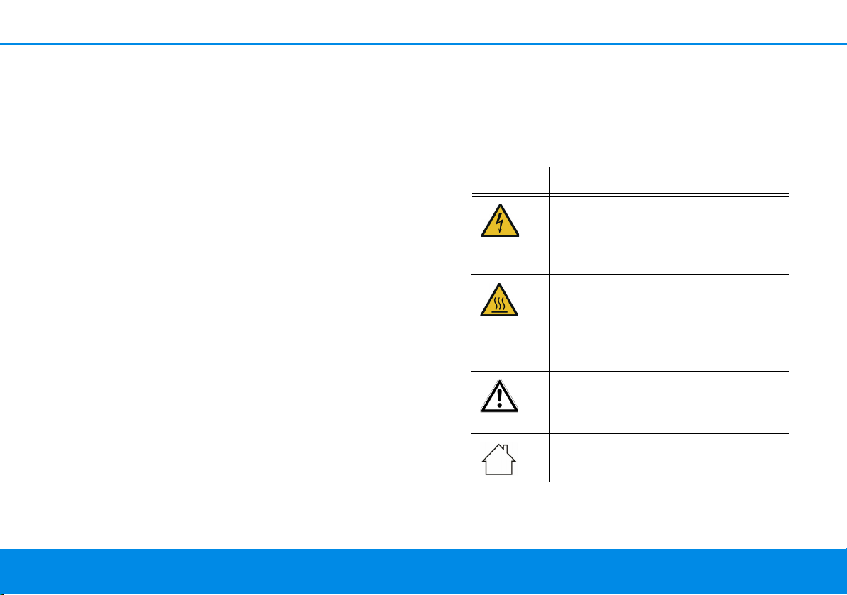
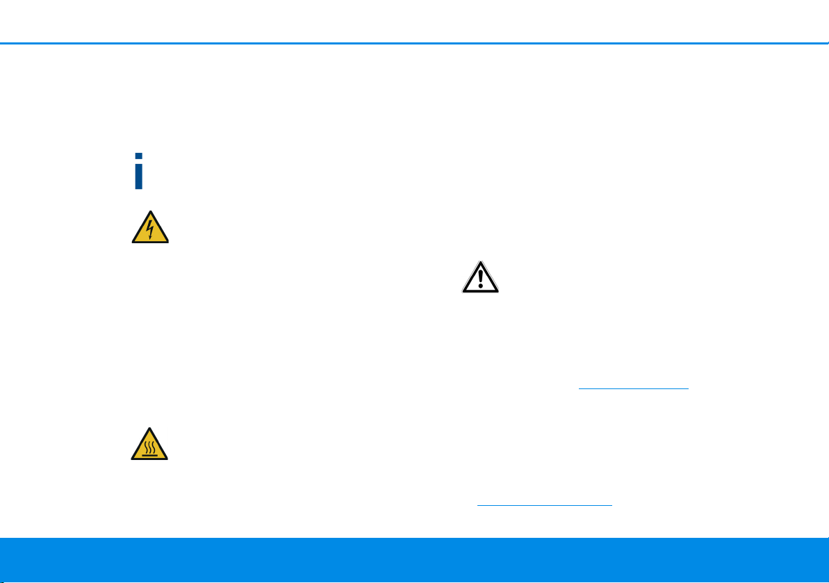
Icon Description
Very important safety symbol that
warns you of imminent electrical
voltage which if not observed can
result in serious injury or death.
An important safety symbol that
warns you of a potentially dangerous situation involving a burn hazard which can result in minor
injuries or damage to property.
An important note that should be
observed which can potentially
lead to material damages.
The device may only be used indoors in dry conditions.
devolo Magic 2 WiFi next
Page 8
Preface 8
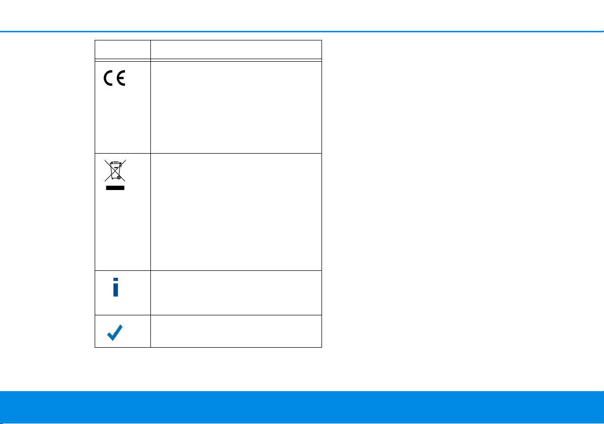
Icon Description
The manufacturer/distributing
company uses the CE marking to
declare that the product meets all
applicable European regulations
and has been subjected to the prescribed conformity assessment
procedures.
It is used to prevent the occurrence
of waste electrical and electronic
equipment and to reduce this type
of waste through reuse, recycling
and other forms of utilisation. The
European Community WEEE Directive establishes minimum standards
for handling waste electrical and
electronic equipment in the EU.
Additional information, background material and configuration
tips for your device.
Indicates a completed course of action
1.2 Intended use
Use devolo products, devolo software and the provided accessories as described to prevent damage
and injury.
Products
devolo products are communication devices designed for indoors.* Depending on the product, they
are equipped with a PLC- (PowerLine Communica-
tion) and/or a Wi-Fi module. Computers, laptops,
smartphones, tablets, smart TVs and other devices
connected this way are integrated into a home
network over the existing electrical wiring and/or
Wi-Fi without any complicated wiring. devolo devices must never be used outdoors because the
high temperature fluctuations and moisture can
damage both the product and the power line. devolo products may not be installed at a height above two metres unless an additional fas-tening
mechanism is available. The products are intended
for operation in the EU, Switzerland and Norway.
* The only exceptions are devolo outdoor products, which are
suited for the outdoor use thanks to their IP certification.
devolo Magic 2 WiFi next
Page 9
9 Preface
Software
devolo devices can be used only with the free,
downloadable programs approved and available
on devolo AG's website (www.devolo.com)
app stores (iOS and Google Play). Any
modifications to the product-specific firmware or
software could damage the products and, in the
worst-case scenario, render them unusable and
negatively affect conformity.
Always use the most up-to-date software version
to make sure you have the latest security functions
and device updates. The installed devolo software
notifies you automatically if a new software version is available.
Accessories
Use only the provided accessories.
and in
1.3 CE Conformity
This product complies with the technical
requirements of the directives 2014/53/
EU, 2011/65/EC and 2009/125/EC.
This product is designed for use in the EU,
Switzerland and Norway.
A printout of the simplified CE declaration of this
product is separately included and can also be
found under
www.devolo.com/support/ce
.
1.4 Safety notes
It is essential to have read and understood all safety and operating instructions before the devolo device is used for the first time; keep them safe for
future reference.
DANGER! Electrical shock caused by
electricity
Do not reach into the electrical socket, do
not open the device and do not insert any
objects into the electrical socket or into the
ventilation openings
Users do not need to carry out any maintenance on
devolo devices. In the event of damage, disconnect
the devolo device from the mains supply by pulling
it or its plug out of the electrical socket. Then contact qualified specialist personnel (after-sales service) exclusively. Damage is deemed to have
occurred, for example,
devolo Magic 2 WiFi next
Page 10
Preface 10
b if the power plug is damaged.if the devolo
device has been showered with liquid (such as
rain or other water).
b if the devolo device is inoperable.
b if the housing of the devolo device is damaged.
Do not plug devolo devices directly into each
other. Devices that are plugged into each other
can experience a decrease in transmission rate.
DANGER! Electric shock caused by
electricity
Device must be plugged into a power
socket with a connected earth wire
devolo devices may be operated only on a mains
power supply as described on the rating plate.
To disconnect devolo devices from the mains supply, unplug the device from the electrical socket.
The power socket and all connected network devices should be easily accessible so that you can
pull the power plug quickly if needed.
CAUTION! Heat development during operation
Certain housing components can become
very hot in certain situations. Attach device
so that it is touch-proof, observing optimal
positioning
devolo devices should only be installed at locations
that guarantee adequate ventilation. Slots and
openings on the housing are used for ventilation:
b Do not cover devolo devices during operation.
b Do not place any objects on devolo devices.
b Do not insert any objects into the openings of
devolo devices.
b devolo devices must not be placed directly
next to a naked flame (such as fire or candles).
b devolo devices must not be exposed to direct
heat radiation (e.g. radiator, direct sunlight).
CAUTION! Damage to housing from
cleaning agents containing solvents
Clean only electroless and with dry cloth
1.5 devolo on the Internet
For detailed information on our products and
devolo Magic, visit www.devolo.com
There you will find product descriptions and documentation, and also updates of devolo software
and your device's firmware.
If you have any further ideas or suggestions related
to our products, please don't hesitate to contact us
at support@devolo.com
!
.
devolo Magic 2 WiFi next
Page 11
11 Introduction
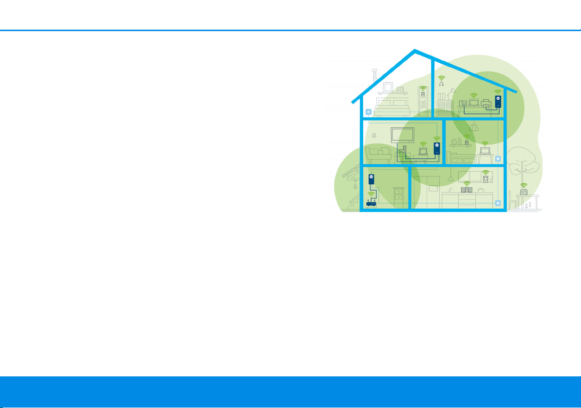
Fig. 1 devolo Magic throughout the home
2 Introduction
2.1 devolo Magic
Home is where devolo Magic is – in no time at all,
devolo Magic transforms your house or flat into a
multimedia home of the future with noticeably
higher speed, more stability and greater range,
providing the perfect Internet experience as a
result!
Be inspired by products that are astonishingly easy
to install, with impressive, innovative technology
and unbeatable performance.
Be ready for the technology of the future today
devolo Magic embodies the new generation of the
tried-and-tested Powerline technology (PLC) based on the cutting-edge G.hn architecture. G.hn
was developed by the International Telecommunication Union (ITU) with ongoing development provided primarily by the HomeGrid Forum industry
association. devolo Magic products are certified
according to HomeGrid standards and are compatible with other HomeGrid-certified products.
devolo Magic 2 WiFi next
Page 12

Introduction 12
Like the HomePlug AV technology used in established devolo dLAN devices, devolo Magic uses the
household mains supply for data transmission and
secures ideal performance and stability in locations
where network cables are not viable or desired
and/or the Wi-Fi frequently falls short due to ceilings and walls.
To set up a devolo Magic network, you need at
least two devolo Magic devices. For technical
reasons, devices from the devolo Magic series
are not compatible with dLAN devices.
2.2 Introduction to the devolo magic adapter
Unpack– plug in – get started and be prepared
for the new generation of the tried-and-tested
Powerline technology and innovative mesh
Wi-Fi with swiftness and stability:
Powerline
b At speeds up to 2400 Mbps
b Over distances up to 500 metres
b Security – with 128-bit AES Powerline encryp-
tion
Mesh Wi-Fi
b At speeds up to 1200 Mbps
b Four antennas cover the 2.4 and 5 GHz Wi-Fi
frequencies at the same time and use the full
extent of the entire 5 GHz frequency band
(Dynamic Frequency Selection, DFS).
b Multi-user MIMO technology – The
devolo Magic 2 WiFi next supplies your smartphone, tablet and other devices with data
streams simultaneously – at the speed you
require and at an efficient transfer rate.
b Air-time fairness – Quicker Wi-Fi devices take
priority in the network.
b Band steering – Use of the optimum frequency
band (2.4 and 5 GHz frequency band)
b Roaming – Quickly and seamlessly connect to
the strongest Wi-Fi access point
b Security – with WPA2/WPA3 for wireless ac
("IEEE 802.11a/b/g/n/ac" Wi-Fi high-speed
standards)
b Convenient additional functions such as
parental controls, guest Wi-Fi, time control and
Config Sync are integrated in the devolo Magic
2 WiFi.
devolo Magic 2 WiFi next
Page 13
13 Introduction
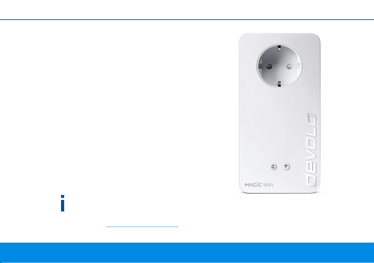
Fig. 2: devolo Magic 2 WiFi next with country-specific
connector and power socket
b Efficiency – The integrated PowerSave mode
reduces energy consumption automatically at
low data traffic.
b The 2 gigabit network connectors on the
devolo Magic 2 WiFi next let you connect
stationary network devices—such as a game
console, TV or media receiver—to your Internet
access point over the Powerline network (e.g.
Internet router).
b Its integrated electrical socket can be used
like a normal wall socket to supply power to an
additional network device or a power strip.
The devolo Magic 2 WiFi next features
b An integrated electrical socket,
b A PLC button with LED status display,
b A Wi-Fi button with LED status display,
b Four internal Wi-Fi antennas,
b Two gigabit network connectors
b A reset button (next to the network connec-
tors).
The LED status displays can be disabled. You
can find more information about this in Chapter
4 Network configuration or in the product
manual for the devolo Cockpit software available online at www.devolo.com/cockpit
.
devolo Magic 2 WiFi next
Page 14
Introduction 14
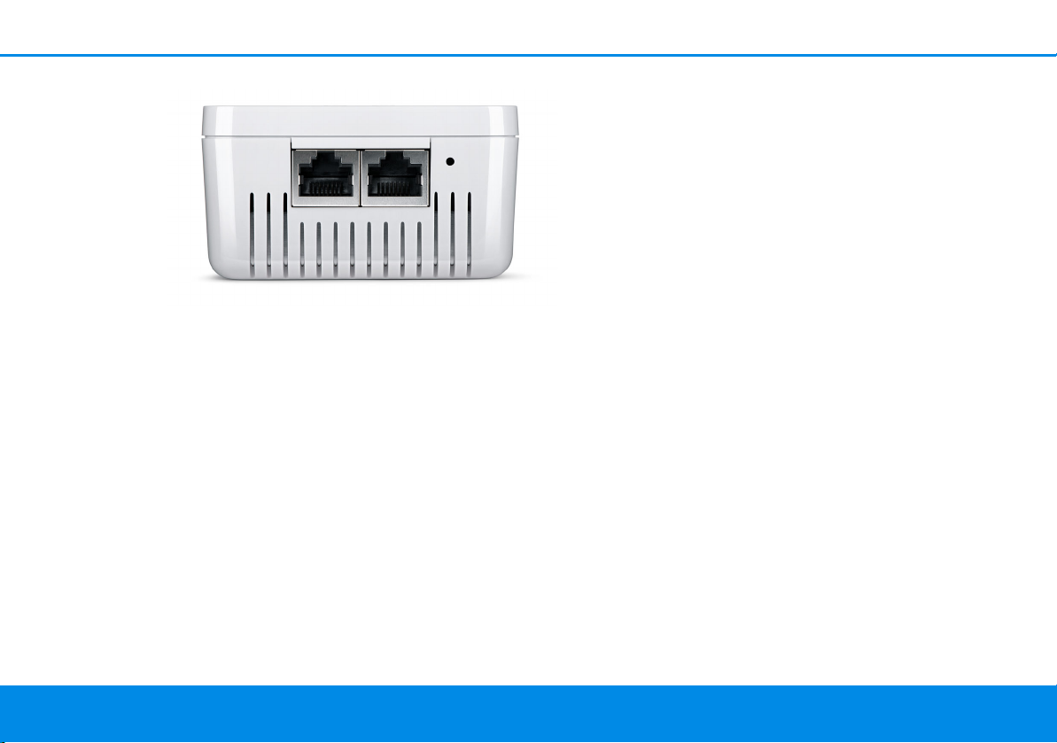
Fig. 3 Network connections
Starting up a new devolo Magic PLC network
After plugging the devolo Magic adapters into
available power sockets, a new devolo Magic network is established automatically within 3 minutes.
Expanding an existing devolo Magic PLC network by adding another devolo Magic adapter
In order to use a new devolo Magic 2 WiFi in your
devolo Magic- network, first you have to connect it
to your existing devolo Magic adapters devices as a
network. This is accomplished by using a shared
PLC password, which can be assigned in various
ways:
b Using devolo Cockpit or the
devolo Home Network App (see Chapter 3.4
Installation of devolo software)
b Using the web interface (see Chapter 4.5
2.3 Pairing – Establishing a PLC connection
devolo Magic adapters that are in the factory default condition, i.e. have been recently purchased
or successfully reset (see Chapter 3.5 Removing
the devolo Magic adapter from a PLC network),
automatically start to attempt to pair (establish a
PLC connection) with anotherdevolo Magic adapter when reconnected to the mains supply.
Powerline)
b Using the PLC button as described below.
devolo Magic 2 WiFi next
Page 15

15 Introduction
1 To do so, plug the new devolo Magic adapter
into an available power socket and, for approximately 1 second, press the PLC button on a
devolo Magic adapter in your existing
devolo Magic network.
2 The new devolo Magic adapter pairs automati-
cally so no button needs to be pressed. The LED
of this adapter now also flashes white.
After a short time, the flashing LED becomes a steady white light. The devolo Magic
adapter has been successfully integrated
into your existing devolo Magic network.
For each pairing operation, only one additional
devolo Magic adapter can be added at a time.
You can find detailed information about installing devolo Magic adapters in Chapter 3.3
Connecting the devolo Magic 2 WiFi next.
devolo Magic 2 WiFi next
Page 16

Introduction 16
2.3.1Reading the PLC indicator light
The integrated PLC indicator light (LED) shows the
status for the devolo Magic 2 WiFi by illuminating
and/or flashing:
LED Flashing be-
haviour
1 Red LED Lights up for
up to 2 sec.
2 Red LED Flashes at in-
tervals of 0.5
sec. (on/off)
devolo Magic 2 WiFi next
Meaning LED status display
(web interface*)
Start-up process Cannot be disabled
Status 1:
The reset of the devolo Magic adapter was
successful. The PLC/reset button has been
pressed and held for 10 seconds.
Status 2:
The devolo Magic adapter (once again) has
the factory default settings. Since the last
reset, no pairing with another devolo Magic
adapter has taken place.
Connect the adapter with another
devolo Magic adapter to create a fullfledged devolo Magic network as described
in Chapter 2.3 Pairing – Establishing a PLC
connection.
Cannot be disabled
Page 17

17 Introduction
LED Flashing be-
haviour
3 Red LED Lights up stea-dyStatus 1:
4Red and
white
LED
Flashes at intervals of 0.1
sec. red/2 sec.
white
Meaning LED status display
The other network nodes are in standby
mode and cannot currently be accessed over
the mains supply. The PLC LEDs of the other
devolo Magic adapters flash white only for a
short time.
Status 2:
The connection to the other network nodes
has been interrupted. There may be electromagnetic or radio frequency interference on
the power line. In this case, put the
devolo Magic adapters closer to each other
or try to shut off the source of interference.
Data transmission rate not in optimum
range **
(web interface*)
Can be disabled
Can be disabled
devolo Magic 2 WiFi next
Page 18

Introduction 18
LED Flashing be-
haviour
5White
LED
6White
LED
7White
LED
8Red and
white
LED
Status 1:
Flashes at
intervals of
0.5 sec.
(on/off)
Status 2:
Flashes at intervals of 1
sec. (on/off)
Lights up steady
Flashes at intervals of
0.1 sec.. on /
5sec. off
Flashes at intervals of
0.5 sec. red/
0.5 sec. white
Meaning LED status display
(web interface*)
Status 1:
This devolo Magic adapter is in pairing
mode and the system is searching for new
devolo Magic adapters.
Status 2:
Someone has triggered the "Identify device"
function on the web interface or in the
devolo Home Network App. This function
identifies the devolo Magic adapter being
sought.
The devolo Magic connection does not have
any issues and the devolo Magic adapter is
ready to operate.
The devolo Magic adapter is in standby mode.***
The devolo Magic adapter is carrying out a
firmware update.
Cannot be disabled
Can be disabled
Can be disabled
Cannot be disabled
devolo Magic 2 WiFi next
Page 19

19 Introduction
Fig. 4: country-specific type plate
* Information about the web interface can be
found in Chapter 4 Network configuration.
** Information on improving the transmission rate
can be found in Chapter 5.2 Bandwidth optimi-
zation.
***A devolo Magic adapter switches to standby
mode after approximately 10 minutes if no active
network device (e.g. computer) is connected to the
network interface and the Wi-Fi is switched off. In
this mode, the devolo Magic adapter cannot be
accessed over the electrical wiring. As soon as the
network device (e.g. computer) connected to the
network interface is switched on again, your
devolo Magic adapter can also be accessed over
the electrical wiring again.
Check whether the adapter is connected to the
mains supply correctly and whether the pairing
operation has been carried out successfully. For
more information about this, refer to 3.3
Connecting the devolo Magic 2 WiFi next.
Wi-Fi on/off
In the factory default settings, the Wi-Fi setting is
already enabled and the Wi-Fi encryption is set to
WPA2. The default WiFi key for the initial
installation of the devolo Magic 2 WiFi next is the
device's WiFi key. You will find the unique key on
the label on the back of the housing.
2.3.2Wi-Fi button
This button controls the following functions:
devolo Magic 2 WiFi next
Page 20

Introduction 20
Before the networking procedure, write down
the Wi-Fi key of the devolo Magic 2 WiFi. You
can find the device's unique key on the label on
the rear side of the housing.
In order to connect the devolo Magic 2 WiFi
with your laptop, tablet or smartphone later via
Wi-Fi, enter the noted Wi-Fi key as the network
security key.
b In order to switch Wi-Fi off, press and hold the
Wi-Fi button longer than 3 seconds.
b In order to switch Wi-Fi back on, briefly tap
the Wi-Fi button.
Connecting Wi-Fi devices via WPS
b If the device is still on factory defaults, tap the
Wi-Fi button in order to activate WPS.
b If the Wi-Fi connection was switched off and
you would like to activate WPS, press the WiFi button twice; once to switch Wi-Fi on, and
again to activate WPS.
b If the Wi-Fi connection is switched on and you
want to copy these settings to another
devolo Magic adapter, continue reading with
the Chapter 4.7.5 Config Sync.
WPS is one of the encryption standards developed by the Wi-Fi Alliance. The objective of
WPS is to make it easier to add devices to an existing network. For more detailed information,
refer to Chapter 4.4.7 Wi-Fi Protected Setup
(WPS).
2.3.3Reading the Wi-Fi indicator light
The integrated Wi-Fi indicator light (LED) shows
the status of the devolo Magic 2 WiFi by illuminating and/or flashing
devolo Magic 2 WiFi next
Page 21

21 Introduction
Wi-Fi-LED Flashing behavior Meaning LED status display
(web interface*)
1 White LED Flashes at intervals
of 0,1 sec. on /
5sec. off
2 White LED Lights up steady Wi-Fi is switched on and active. Can be disabled
3 White LED Off Status 1:
* Information about the web interface can be
found in Chapter 4 Network configuration.
The devolo Magic adapter is in
WPS mode to integrate Wi-Fienabled devices via WPS.
The Wi-Fi LED is switched off and
the devolo magic adapter is still
ready for use.
Status 2:
The Wi-Fi function ist disabled.
Cannot be disabled
Can be disabled
devolo Magic 2 WiFi next
Page 22

Introduction 22
2.3.4Reset button
The reset button (next to the network jacks) has
two different functions:
Restart
The device restarts if you press the Reset button for
less than 10 seconds.
Factory default settings
1 To remove a devolo Magic adapter from your
devolo Magic network and successfully restore
its entire configuration to the factory defaults,
press and hold the reset button longer than
10 seconds.
Keep in mind that all settings that have already
been made will be lost!
2 Wait until the LED flashes white and then dis-
connect the devolo Magic adapter from the
mains supply.
The devolo Magic adapter has been
successfully removed from your existing
devolo Magic network.
2.3.5Network jacks
You can use the network jacks on the
devolo Magic adapter to connect it to stationary
devices such as computers, game consoles, etc.
using a standard network cable.
2.3.6Wi-Fi antennas
The internal Wi-Fi antennas are for connecting to
other network devices wirelessly.
2.3.7Integrated electrical socket
Always use the integrated electrical socket on the
devolo Magic adapter when connecting other
consumers to the mains supply. In particular,
electronic devices with mains adapter can
negatively affect PLC performance.
The integrated mains filter in the devolo Magic
adapter filters any such external interference and
reduces any impairment of PLC performance.
devolo Magic 2 WiFi next
Page 23

23 Initial use
3Initial use
This chapter tells you everything you need to know
to set up and use your devolo Magic 2 WiFi next .
We describe how to connect the device and briefly
describe the devolo software that comes with it.
For more information, please visit our website
www.devolo.com
3.1 Package contents
Please ensure that the delivery is complete before
beginning with the installation of your
devolo Magic 2 WiFi next :
b Single Kit:
a 1 devolo Magic 2 WiFi next
a Hard copy of installation guide
a Printed security flyer
a Simplified CE declaration
or
b Starter Kit:
a 1 devolo Magic 2 WiFi next
a 1 devolo Magic 2 LAN
a 1 network cable
a Hard copy of installation guide
.
1-1
a Printed security flyer
a Simplified CE declaration
or
b Multiroom Kit:
a 2 devolo Magic 2 WiFi next
a 1 devolo Magic 2 LAN
a 1 network cable
a Hard copy of installation guide
a Printed security flyer
a Simplified CE declaration
devolo AG reserves the right to change the
package contents without prior notice.
1-1
3.2 System requirements
b Operating systems supported by
devolo Cockpit:
a from Windows 7 (32-bit/64-bit),
a from Ubuntu 13.10 (32-bit/64-bit),
a from Mac (OS X 10.9)
b Network connection
devolo Magic 2 WiFi next
Page 24

Initial use 24
Please note that your computer or other device
must have a network card or network adapter
with a network interface.
To set up a devolo Magic network, you need at
least two devolo Magic adapters.
3.3 Connecting the devolo Magic 2 WiFi next
CAUTION! Damage to the device caused
by ambient conditions
Only use device indoors in dry conditions
In the following sections we describe how to
connect the devolo Magic 2 WiFi next and integrate it into a network. We clarify the exact procedures based on potential network scenarios.
For the permitted voltage range for operating
the device and the power consumption, refer to
the type plate on the rear of the device. For additional technical information on our products,
refer to the product area at
www.devolo.com
.
3.3.1Starter Kit – Automatic set-up for a new devolo Magic PLC network
1 Connect one devolo Magic 2 LAN
Internet access device's network connection
(e.g. your Internet router).
CAUTION! Tripping hazard
Lay the network cable in a barrier-free
manner and ensure that the electrical
socket and the connected network devices are easily accessible
2 Plug both devolo Magic adapters into available
power sockets within 3 minutes. As soon as the
LEDs on both adapters flash white at regular
intervals of 0.5 sec., they are ready to operate
and automatically start the process of establishing an encrypted connection to each other
(see Chapter 2.3.1 Reading the PLC indicator
light).
If the LEDs on both devolo Magic adapters
light up in white, then your devolo Magic
network has been set up according to your
individual specifications and is protected
from unauthorised access.
1-1
to your
devolo Magic 2 WiFi next
Page 25

25 Initial use
3.3.2Addition – Expanding an existing PLC network by adding another devolo Magic 2 WiFi next
Before you can use the devolo Magic 2 WiFi next
in your devolo Magic network, first you have to
connect it to your existing devolo Magic adapters
as a network. This is accomplished by using a shared password.
1 Plug the devolo Magic 2 WiFi next into an
available power socket. As soon as the LED
flashes white at regular intervals of
0.5 seconds, the adapter is ready to operate
but not yet integrated into a devolo Magic
network (see Chapter 2.3.1 Reading the PLC
indicator light).
2 Within 3 minutes, press the PLC button on a
devolo Magic adapter in your existing
devolo Magic network for approximately 1 sec.
The new devolo Magic adapter pairs automatically so no button needs to be pressed. The LED
of this adapter now also flashes white.
If the LEDs light up white on both
devolo Magic adapters, the new adapter
has been successfully integrated into your
existing devolo Magic network.
For each pairing operation, only one additional
adapter can be added at a time.
3.3.3Changing the network password
A network password can also be changed in the
following ways:
b Using the web interface of the devolo Magic
adapter (see Chapter 4.5 Powerline)
or
b Using devolo Cockpit or the
devolo Home Network App. For more infor-
mation, refer to the chapter. 3.4 Installation of
devolo software
3.3.4Establish a Wi-Fi connection with the devolo Magic 2 WiFi next
Establish the Wi-Fi connection with your laptop,
tablet or smartphone by entering the previously
noted WiFi key as the network security key.
Integrate the Wi-Fi adapter into an existing WiFi network
To ensure that the devolo Magic2WiFinext has
the same Wi-Fi configuration as your Wi-Fi router,
you can apply the Wi-Fi access data at the touch of
a button using the WiFi Clone function. This can
be enabled in different ways:
devolo Magic 2 WiFi next
Page 26

Initial use 26
Activating WiFi Clone:
b Activating WiFi Clone by pressing a button:
First press the Wi-Fi button with the Wi-Fi icon
on the front side of the
devolo Magic 2 WiFi next and then press the
WPS button of the Wi-Fi router with the access
data you want to apply.
or
b Activating WiFi Clone from the web interface.
More information about this function can be
found in Chapter WiFi Clone.
3.4 Installation of devolo software
Installing devolo Cockpit software
devolo Cockpit finds all accessible devolo Magic
adapters in your devolo Magic network, displays
information about these devices and encrypts your
devolo Magic network individually. You can use
the software to navigate to the integrated web interface.
Operating systems supported by devolo Cockpit
(Version 5.0 or later):
b from Ubuntu 13.10 (32-bit/64-bit),
b from Mac (OS X 10.9)
You can find the product manual, software and
additional information on devolo Cockpit online at www.devolo.com/cockpit
Downloading the devolo Home Network App
The devolo Home Network App is devolo's free
app also for checking and configuring WiFi, Magic
and LAN connections for the devolo Magic adapter
(using a smartphone or tablet). The smartphone or
tablet connects to the devolo Magic adapter at
home over Wi-Fi.
1 Download the devolo Home Network App to
your smartphone or tablet computer from the
corresponding store.
2 The devolo Home Network App is placed in
your smartphone's or tablet's app list as usual.
Tapping on the devolo Home Network App
icon brings you to the start menu.
You can find more information about the
devolo Home Network App online at
www.devolo.com/devolo-app
.
.
b from Windows 7 (32-bit/64-bit) or later,
devolo Magic 2 WiFi next
Page 27

27 Initial use
3.5 Removing the devolo Magic adapter from a PLC network
To remove a devolo Magic adapter from your network and successfully restore its entire configuration to the factory default settings, press the reset
button longer than 10 seconds. Wait until the LED
flashes white and then disconnect the adapter
from the mains supply.
Keep in mind that all settings that have already
been made will be lost!
To integrate the mains supply into another network, proceed as described in Chapter 3.3.2 Addi-
tion – Expanding an existing PLC network by
adding another devolo Magic 2 WiFi next.
devolo Magic 2 WiFi next
Page 28

Network configuration 28
4 Network configuration
The devolo Magic 2 WiFi next has a built-in web interface that can be called up using a standard web
browser. All settings for operating the device can
be modified here.
4.1 Calling up the built-in web interface
You can access the built-in online web interface for
the devolo Magic 2 WiFi next in different ways:
b Using the devolo Home Network App on your
smartphone or tablet, you can access the
device's web interface by tapping on the corresponding adapter symbol for the
devolo Magic 2 WiFi next.
or
b Using the Cockpit software, you can get to the
device's web interface by clicking on the corresponding tab for the devolo Magic 2 WiFi next.
Then the program determines the current IP
address and starts the configuration in the web
browser.
By default, the web interface will open directly. However, if an access password has been
set via the option System Management,
you have to enter that password first. Read
more about this under 4.7 System.
You can find more information on
devolo Home Network App and Cockpit software in Chapter 3.4 Installation of devolo
software.
4.2 General information about the menu
All menu functions are described in the corresponding interface as well as in the associated chapter
in the manual. The sequence of the description in
the manual follows the structure of the menu. The
figures for the device interface serve as examples.
Logging in
The web interface is not password protected. Assigning a login password is mandatory when logging in for the first time to prevent unauthorised
access by third parties.
devolo Magic 2 WiFi next
Page 29

29 Network configuration
Enter your existing password each time you login
again and confirm by pressing Log in.
Logging out
Log out of the web interface by clicking Log
out.
Language selection
Select the desired language in the
language selection list.
The central areas of the web interface and their
sub-categories are listed on the left edge. Click the
entry for an area to move directly into it.
Making changes
Once you make a change, two icons are shown on
the corresponding menu page:
b Disk icon: Your settings are being saved.
b X icon: The operation is being cancelled. Your
settings are not being saved.
Required fields
Fields with a red border are required fields. This
means entries must be made in these fields to continue with the configuration.
devolo Magic 2 WiFi next
Page 30

Network configuration 30
Help text blank fields
Fields that have not been filled in yet contain greyed out help text, which indicates the required content for the field. This help text disappears
immediately once content has been entered.
Default settings
Some fields contain default settings which ensure
the greatest amount of compatibility and ease of
use. Default settings are identified with an * in
drop-down menus.
Default settings can of course be replaced with customised information.
Recommended settings
Some fields include recommended settings.
Recommended settings can of course be replaced
with customised information.
Tables
You can make changes within a table by clicking
the corresponding table row in Time Control and
Parental Control. In edit mode, the corresponding
table rows have a blue background. In edit mode,
the corresponding table rows have a blue
background.
Invalid entries
Entry errors are either highlighted by a red border
or error messages are shown.
Buttons
Click the Disk icon to save the settings for the
respective web interface area.
Click the X icon or use the Menu path above the
buttons to exit the respective web interface area.
Click the Recycle bin icon to delete an entry.
Click the Arrow icon to refresh a list.
devolo Magic 2 WiFi next
Page 31

31 Network configuration
4.3 Overview
The Overview area shows the status of the
devolo Magic 2 WiFi next and the connected LAN,
PLC and Wi-Fi devices.
4.3.1System
Name: Device name
Serial number: Device serial number
Firmware version: Firmware version of the device
4.3.2Wi-Fi
2.4 GHz
Current channel: used frequency channel in the
2.4-GHz frequency range
Enabled SSID: name of the enabled Wi-Fi network
Connected Wi-Fi clients: number of devices
connected to the network.
5 GHz
Current channel: used frequency channel in the 5-
GHz frequency range
Enabled SSIDs: Name of the enabled Wi-Fi
networks
Connected Wi-Fi clients: number of devices
connected to the network.
4.3.3Powerline
Local device
Network: status information “connected“ or “not
connected“
Network
Connected clients: number of devices connected
to the Powerline network
devolo Magic 2 WiFi next
Page 32

Network configuration 32
4.3.4LAN
IPv4
Protocol: Display indicating whether DHCP is swit-
ched on or switched off
Address: IPv4 address in use
Subnet mask: IPv4 network mask in use
Default gateway: IPv4 gateway in use
Name server: DNSv4 server in use
IPv6
Protocol: Display indicating whether DHCPv6 is
switched on or switched off
Address/subnet: Address/subnet mask in use
4.4 Wi-Fi
Make all changes to your wireless network in the
Wi-Fi area.
devolo Magic 2 WiFi next
Page 33

33 Network configuration
4.4.1Status
You can see the current status of your Wi-Fi network configuration here, e.g. the connected Wi-Fi
stations, the MAC address, the selected frequency
band, the SSID, the transfer rates and the connection duration.
4.4.2Wi-Fi networks
You can make all necessary changes to your Wi-Fi
network here.
devolo Magic 2 WiFi next
Wi-Fi network mode
The devolo Magic 2 WiFi next supports both the
parallel operation of the Wi-Fi frequency bands
and their separate use.
Page 34

Network configuration 34
The Wi-Fi network mode field lets you define your
preferred setting by clicking the respective field:
b 2.4 GHz + 5 GHz – Both frequency bands are
used
b 2.4 GHz – Only the 2.4 GHz frequency band is
used
b 5 GHz – Only the 5 GHz frequency band is used
b Off – If desired, you can completely switch off
the Wi-Fi section of your
devolo Magic 2 WiFi next here.
Keep in mind that after saving this setting, you will be disconnected from any
existing wireless connection to the
devolo Magic 2 WiFi next. In this case,
configure the device over Ethernet.
Network name
The network name (SSID) determines the name of
your wireless network. You can see this name
when logging onto the Wi-Fi, allowing you to
identify the correct Wi-Fi network.
Channels
There are 13 channels available in the 2.4 GHz
frequency band. The channels recommended for
Europe are channels 1, 6 and 11. This ensures the
frequency bands of the channels do not overlap
and any connection problems are avoided.
There are 19 channels available in the 5 GHz
frequency band.
The channel selection default setting is
Automatic.
The devolo Magic 2 WiFi next regularly and
automatically executes the channel selection in
this setting. In other words, if the last connected
station logs out, a search for a suitable channel is
carried out immediately. If no stations are
connected, the device automatically selects a
channel every 15 minutes.
It is worth noting that connected devices also have
to support the increased frequency band of 5 GHz.
From channel 52 onward you go into the radar
range. When accessing the device for the first time,
a radar detection phase (DFS) starts automatically,
during which time the devolo Magic 2 WiFi next
cannot be accessed via Wi-Fi. This can take up to 10
minutes.
In the Channel field, you can manually select a 2.4
GHz and a 5 GHz channel. If you are not sure which
wireless channels are used by nearby devices,
select the Automatic option.
devolo Magic 2 WiFi next
Page 35

35 Network configuration
Hide SSID:
The SSID specifies the name of your wireless network. You can see this name when logging onto
the Wi-Fi, allowing you to identify the correct subnet.
If the Hide SSID option is disabled, your network
name is visible. If this option is disabled, potential
network users must know the exact SSID and enter
it manually to be able to set up a connection.
Some Wi-Fi stations have difficulty connecting
to hidden wireless networks. If the connection
to a hidden SSID poses problems, first try to set
up the connection with a visible SSID and only
then try to hide it.
Security
The WPA/WPA2/WPA3 Personal (Wi-Fi
Protected Access) security standard is available for
securing data transmission in your wireless
network. This method allows for individualised
keys consisting of letters and numbers and the
depicted special characters with a length of up
to 63 characters. You can simply enter them into
the Key field via the keyboard.
4.4.3Guest network
If you have friends or acquaintances visiting and
you want to provide them with Internet access but
without giving away the password for your Wi-Fi,
you can set up a separate guest account in addition
to the main Internet connection. The guest account can have its own network name, time limit
and Wi-Fi password. This way your visitors can
browse the Internet without having access to your
local network.
To set up a guest account, activate the Enable
option.
devolo Magic 2 WiFi next
Page 36

Network configuration 36
The guest account has an Automatic shutoff feature. This feature automatically disables the guest
network once the selected time period ends.
You can use the Enable option to activate the
shut-off feature.
You can also enable or disable the guest account in the devolo Home Network App
using the Guest account button.
Frequency band
In the Frequency band field, you select the frequency band mode you are using (see Chapter Wi-
Fi network mode).
Network name
Define the name of the guest network in the Network name field.
Key
You should also encrypt the guest account to prevent anyone in signal range from intruding into
your network and, for example, sharing your Internet connection. The WPA/WPA2/WPA3 (Wi-Fi
Protected Access) security standard is available for
this.
This method allows for individualised keys consisting of letters and numbers with a length of up
to 63 characters. You can simply enter them via
the keyboard.
To do so, enter a corresponding number of characters into the Key field.
QR code
Using the QR code, you can conveniently set up the
connection to the guest network for mobile devices. Scanning the QR code automatically transfers the credentials for the guest network to the
respective mobile device. The QR code is visible
only if the guest network has been enabled.
4.4.4Mesh
Mesh
All devolo Magic Wi-Fi adapters offer mesh Wi-Fi,
which entails completely new and improved Wi-Fi
functions:
b Multi-user MIMO technology
More often than not, you use multiple end
devices in your Wi-Fi network, such as a smartphone, tablet, smart TV or a game console. This
can present a real challenge for your Wi-Fi network—it has to regulate the distribution of
data streams from the Wi-Fi access point (e.g.
router, devolo device) to the end devices.
devolo Magic 2 WiFi next
Page 37

37 Network configuration
Multi-user MIMO technology makes it possible
for your devolo device to supply your smartphone, tablet and other devices with data
streams simultaneously—at the speed you
require and at an efficient transfer rate.
Thanks to Multi-user MIMO technology, you
can finally enjoy using the Internet without
long wait times during online gaming, sporadic
drop-outs while streaming in HD or slow
downloads.
b Fast roaming (IEEE 802.11r) streamlines the
registration process for Wi-Fi end devices, such
as smartphones or tablets, when switching to
another Wi-Fi hotspot.
The feature Fast roaming is not compatible
with all Wi-Fi clients. If there will be connection
problems with one of your devices, please
deactivate these option.
In factory default condition of the
devolo Magic 2 WiFi next Fast roaming is turned
off by default.
b In addition, the new air-time fairness feature
processes the requests of high-speed Wi-Fi clients at higher priority. This prevents older
devices, which may require more time for a
download, from creating Wi-Fi bottlenecks.
b The access-point steering feature (AP stee-
ring) function enhances your Wi-Fi access
point by adding intelligent network optimisation. This function actively helps your end
devices connect to the optimal network access
point. If the Wi-Fi access point identifies another Wi-Fi access point within your own network that has a stronger signal and better
reception, it redirects the end device to that
point automatically.
In particular, older smartphones, tablets and the
like will remain connected to their Wi-Fi access
point (e.g. router, devolo device) until the signal
gets interrupted. Only then will they switch to a
new Wi-Fi access point with better reception.
b Integrated band steering ensures that all Wi-Fi
stations automatically switch to the optimum
frequency band (2.4 and 5 GHz frequency
band) in order to use the best Wi-Fi connection
at all times.
In order to turn the mesh functions on, activate the
Enable option.
The mesh function of the devolo Magic 2 WiFi next
is switched on by default.
devolo Magic 2 WiFi next
Page 38

Network configuration 38
4.4.5Schedule control
The Schedule control area lets you define when
and if your Wi-Fi is switched on and off.
WiFi Clone
WiFi Clone makes it possible to simply copy the
Wi-Fi configuration data of an existing Wi-Fi access
point (e.g. your Wi-Fi router) to all Wi-Fi access
points (Single SSID). Start the procedure with the
Start Configuration option and then press the
WPS button of the device with the Wi-Fi access
data (SSID and Wi-Fi password) to be applied.
Enabling Wi-Fi schedule control
In order to be able to use time control, activate the
Enable option.
Configuration
You can define multiple time periods during which
your wireless network is to be enabled for each
devolo Magic 2 WiFi next
Page 39

39 Network configuration
weekday. Then the time control automatically
switches the wireless network on or off.
Automatic disconnection
If you enable the Automatic disconnection option, the wireless network is not switched off until
the last station has logged off.
Manually switching the device on and off (using
a button) always has priority over automatic
time control. The configured time control then
takes effect automatically during the next defined time period.
4.4.6Parental control
You can regulate Wi-Fi access for specific devices
based on time using this function. For instance, to
prevent your children from using the Internet
excessively, you can define how long they may use
the Wi-Fi per day. Synchronisation with an
(Internet) time server is necessary to be able to use
the parental control. In this case, the time server
(System Management Time Server (NTP))
for the devolo Magic 2 WiFi next ac has to be
enabled and an active Internet connection is also
required.
The time server pool.ntp.org is enabled by default. You can find more information in Chapter
4.7.2 Management.
If you would like to set up a time quota (usage
ti me i n ho urs ) or a time period (active from/to), activate the Enable option. Now enter the MAC addresses of the devices you want to set up parental
control for.
Under Type, define either a time quota (time limit)
or a time period for when you want the MAC addresses entered to receive Internet access. Under
Select interval, select the desired time frame.
devolo Magic 2 WiFi next
Page 40

Network configuration 40
Setting the time quota
Under Time Quota, the time limit can be selected.
Confirm your settings by clicking the Disk icon.
Setting the time period
Under Time Period, the desired time period can be
selected. After entering the interval, enter the
desired start and end times in hour and minute
format.
Confirm your settings by clicking the Disk icon.
If you want to delete a time quota (time limit) or a
time period from the list, click/touch the dustbin
icon.
4.4.7Wi-Fi Protected Setup (WPS)
Wi-Fi Protected Setup (WPS) is one of the international encryption standards developed by the Wi-Fi
Alliance for easily and quickly setting up a secure
wireless network. The encryption keys of the respective Wi-Fi devices are transmitted automatically and continuously to the other Wi-Fi device(s) in
the wireless network.
Enabling WPS encryption
In order to be able to use WPS encryption, activate
the Enable option.
devolo Magic 2 WiFi next
The devolo Magic 2 WiFi next offers two different
variants for transmitting these encryption keys:
WPS using WPS pushbutton
1 Start the encryption process on the
devolo Magic 2 WiFi next
a By pressing the Wi-Fi button on the front
side of the device or
a By pressing the corresponding Start button
on the user interface under Wi-Fi WPS
Pushbutton.
2 Then either press the WPS key of the Wi-Fi
device you are adding or enable the WPS
mechanism in the Wi-Fi settings of the Wi-Fi
device. Now the devices exchange their encryption keys and establish a secure Wi-Fi connec-
Page 41

41 Network configuration
tion. The Wi-Fi LED on the front panel indicates
the synchronisation process by flashing.
WPS via PIN
To interconnect Wi-Fi devices in your wireless network securely using a PIN variant, go to the web interface and, under Wi-Fi WPS WPS PIN, enter
the WPS PIN generated by your Android smartphone or tablet and start the encryption process by
pressing the corresponding Start button.
Use of the WPS method implies the use of the
WPA/WPA2 encryption standard. Therefore take
note of the following automatic settings:
b If under Wi-Fi Wi-Fi networks, the No
encryption option is selected in advance,
WPA2 is set automatically. The newly generated password is displayed under Wi-Fi Wi-Fi
networks in the Key field.
b If under Wi-Fi Wi-Fi networks, the WPA/
WPA2 option is selected in advance, this set-
ting remains with the previously assigned
password.
4.4.8Neighbour networks
The Neighbour networks area displays visible
wireless networks in your surroundings.
devolo Magic 2 WiFi next
Page 42

Network configuration 42
4.5 Powerline
Make all changes to your PLC network in the Powerline area.
In order to use a new devolo Magic 2 WiFi next in
your devolo Magic network, first you have to
connect it to your existing devolo Magic adapters
devices as a network. This is accomplished by using
a shared password. This can be assigned in different ways:
b Using devolo Cockpit or the
devolo Home Network App (see Chapter 3.4
Installation of devolo software),
b Only using the PLC button (see Chapter 2.3
Pairing – Establishing a PLC connection and
3.3 Connecting the
devolo Magic 2 WiFi next)
b Using the web interface, in the PLC menu; as
described below:
Pairing – Using on-screen button
1 Click Start pairing to start the pairing opera-
tion. This may take some time.
2 As soon as the new devolo Magic adapter is
integrated into your existing network, it
appears in a list of available and established
connections.
Pairing – Using custom password
You can also assign your network a custom PLC
password you pick yourself. Enter this password for
each devolo Magic adapter in the Network
password field and confirm your settings by
clicking the Disk icon.
Note that the custom password is not assigned
to the whole PLC network automatically. Instead, you must assign it separately to each of
your devolo Magic adapters.
Unpairing – Removing an adapter from a network
1 To remove a devolo Magic adapter from your
devolo Magic network, click Leave Powerline
network.
devolo Magic 2 WiFi next
Page 43

43 Network configuration
2 Wait until the LED flashes red and then dis-
connect the devolo Magic adapter from the
mains supply.
Compatibility mode
Using as VDSL connection may negatively impact
the performance of the bandwidth connection.
Select from among the following settings in order
to mitigate any potential negative effects.
Operating mode:
b MIMO
b SISO
Signal transmission profiles:
b Full power
b VDSL 17a (default)
b VDSL 35b
Get in touch with your internet provider to find
out which signal transmission profile is the best
option for your internet connection.
Connections
The table lists all available and connected
devolo Magic adapters for your network along
with displaying the following details:
Device ID: Device ID* (number) of the respective
devolo Magic adapter in the devolo Magic network
* indicates the local devolo Magic adapter
MAC address: MAC address of the respective
devolo Magic adapter
Send (Mbps): Rate for sending data
Receive (Mbps): Rate for receiving data
The MIMO operating mode and the VDSL 17a signal transmission profile are configured by default.
devolo Magic 2 WiFi next
Page 44

Network configuration 44
4.6 LAN
You make changes to the network settings in the
LAN area.
network connectors Port 1 and Port 2 (e.g. PC,
NAS, etc.).
IPv4/IPv6
Depending on how the devolo Magic 2 WiFi next
is connected to the Internet (IPv4 or IPv6), current
network information is displayed, such as Address,
Subnet mask, Standard gateway and DNS server.
4.6.2IPv4/IPv6 configuration
In the factory default settings, only the Retrieve
network settings from a DHCP server option for
IPv4 is enabled. This means that the IPv4 address is
retrieved automatically from a DHCP server. The
currently assigned network data are visible (greyed
out).
If a DHCP server is already present on the network
for assigning IP addresses (e.g. your Internet router), you should leave the Retrieve network set-
tings from a DHCP server option enabled so that
the devolo Magic 2 WiFi next automatically receives an address from it.
4.6.1Status
You can see the current LAN status of the
devolo Magic adapters here. The Ethernet area
shows the network devices connected to the two
If you want to assign a static IP address, make
entries accordingly for the Address, Subnet mask,
Default gateway and DNS server fields.
Confirm your settings by clicking the Disk icon.
devolo Magic 2 WiFi next
Page 45

45 Network configuration
Then, restart the devolo Magic adapter (see Chapter 4.7.3 Configuration) to ensure that your changes take effect.
IPv6 configuration
If you want automatic IP address assignment and
there is already a DHCP server present on the network for assigning IP addresses (e.g. your Internet
router), enable the Retrieve network settings
from a DHCP server option to ensure that the
devolo Magic 2 WiFi next automatically receives
an address from it.
If you want to assign a static IP address, make
entries accordingly for the Address, Subnet mask,
Default gateway and DNS server fields.
Confirm your settings by clicking the Disk icon.
4.7 System
In the System area, you can configure the settings
for security and other devolo Magic adapter device
functions.
4.7.1Status
Here you can view the most important information
on the devolo Magic adapter, including the current
date and time, time zone, MAC address of the
adapter, status of the Wi-Fi and Powerline LEDs
and the two operating buttons.
4.7.2Management
System information lets you enter user-defined
names in the Device name (hostname) and
Device location fields. Both pieces of information
are particularly helpful if multiple devolo Magic
adapters are to be used and identified in the
network.
devolo Magic 2 WiFi next
Page 46

Network configuration 46
Under Change access password, a login password
can be set for accessing the web interface.
By default, the built-in web interface of the
devolo Magic 2 WiFi next is not protected by a
password. We recommend assigning a password
when the installation of the
devolo Magic 2 WiFi next is complete to protect it
against tampering by third parties.
To do so, enter the desired new password twice.
Now the web interface is protected against unauthorised access with your custom password!
In Power Management, you can enable Power-
save mode and Standby mode on the
devolo Magic 2 WiFi next.
If Powersave mode has been enabled, the
devolo Magic 2 WiFi next switches to PowerSave
mode automatically whenever reduced data transmission over ethernet is detected.
The latency (time for transmitting a data
packet) may be negatively affected.
If Standby mode is enabled, the
devolo Magic 2 WiFi next automatically switches
to Standby mode if no ethernet connection has
been enabled, i.e. if no network device (e.g. com-
puter) is switched on and connected to the network interface and if Wi-Fi is disabled.
In this mode, the devolo Magic 2 WiFi next is not
accessible over the Powerline network. As soon as
the network device (e.g. computer) connected to
the network interface is switched on again, your
adapter can also be accessed over the electrical
wiring again.
Powersave mode is disabled in the
devolo Magic 2 WiFi next factory default settings.
Standby mode is enabled in the
devolo Magic 2 WiFi next factory default condition.
The LED settings let you disable the LED status display of the Wi-Fi and Powerline LEDs.
An error status is indicated by corresponding flashing behaviour regardless of this setting.
For information on the LED behaviour of the
devolo Magic adapter in standby mode, refer to
Chapter 2.3.1 Reading the PLC indicator
light.
You can completely disable the operating buttons on the devolo Magic adapter in order to pro-
tect yourself against possible changes. Simply
devolo Magic 2 WiFi next
Page 47

47 Network configuration
disable the Enable PLC button or Enable Wi-Fi
button option.
The operating buttons are enabled in the
devolo Magic 2 WiFi next factory default settings.
Under Time zone, you can select the current time
zone, e.g. Europe/Berlin. The Time server (NTP)
option lets you specify a time server. A time server
is a server on the Internet whose task consists of
providing the exact time. Most time servers are
coupled with a radio clock. Select your time zone
and time server; the devolo Magic 2 WiFi next automatically switches between standard time and
summer time.
4.7.3Configuration
Saving the device configuration
To save the enabled configuration to your computer as a file, select the corresponding button in the
System Configuration Save Configuration
to File area. The system starts downloading the
current device configuration.
Restoring the device configuration
An existing configuration file can be sent to the
devolo Magic 2 WiFi next in the System Confi-
guration area and enabled there. Select a suitable
file via the Select file ... button and start the operation by clicking the Restore button.
Factory Settings
The devolo Magic 2 WiFi next is reset to the original factory defaults in the System Configurati-
on area with the Factory Reset option.
Doing so causes you to lose your personal Wi-Fi
and PLC settings. The last-assigned passwords
for the devolo Magic 2 WiFi next are also reset.
For backup purposes, all active configuration settings can be transmitted to your computer, stored
there as a file and reloaded into the
devolo Magic 2 WiFi next. This function can be
useful for creating a variety of configurations that
will let you quickly and easily set up the device for
use in different network environments.
Reboot device
In order to reboot the devolo Magic 2 WiFi next,
select the Reboot button in the System Confi-
guration area.
4.7.4Firmware
The firmware of the devolo Magic 2 WiFi next includes the software for operating the device. If
necessary, devolo offers new versions on the Inter-
devolo Magic 2 WiFi next
Page 48

Network configuration 48
net as a file download, for example to modify existing functions.
Current firmware
The currently installed firmware of the
devolo Magic 2 WiFi next is displayed here.
Searching for and updating firmware
automatically
The adapter
automatically. To do this, enable the Regulary
check for firmware updates option.
The devolo Magic 2 WiFi next lets you know
when a new firmware version becomes
available. The option is enabled by default.
The Automatically install firmware updates option allows the adapter to automatically install the
firmware it has found.
The devolo Magic 2 WiFi next automatically
updates its firmware. The option is enabled by
default.
Download updated firmware
1 If you have downloaded an updated firm-
ware file for the devolo Magic 2 WiFi next to
your computer, navigate to the System
can also look for up-to-date firmware
Firmware Update firmware area. Click
Browse … and select the downloaded file.
2 Confirm the update procedure with Update
firmware. After a successful update, the
devolo Magic 2 WiFi next restarts automatically.
Ensure that the update procedure is not
interrupted.
4.7.5Config Sync
Config Sync allows settings to be configured uni-
formly for all devolo Magic devices in the network.
This includes the following settings e.g.:
b Wi-Fi network
b Guest network
b Mesh Wi-Fi
b Time control and time server settings.
In order to switch Config Sync on, activate the
Enable option.
Please note that the Wi-Fi is always switched on
or off for the entire network. Therefore, stop
Config Sync first on a device that you want to
configure or switch separately.
devolo Magic 2 WiFi next
Page 49

49 Appendix
Fig.5: devolo Magic bandwidth optimization
5 Appendix
5.1 Technical specifications
Security 128 Bit AES
Device port 2x RJ45
(Gigabit Ethernet port)
Power consumption
Power supply internal
Temperature (Storage/Operating)
Dimensions (in mm,
without plug)
Ambient conditions 10-90% Humidity, non-
Maximum: 12.1 W
Typical: 8.9 W
Stand-by: 3.1 W
196-250 V AC
50 Hz
-25°C to 70 °C / 0°C to
40°C
152x76x40 (HxWxD)
condensing
5.2 Bandwidth optimization
To significantly improve the transmission capacity
of the network, we recommend that you comply
with the following "connection rules":
b Plug the devolo Magic 2 WiFi next directly into
a wall socket. Avoid using power strips. This
may impair the transmission of the PLC signals.
b If there are several sockets in the wall directly
next to each other, they behave like a power
strip. Individual sockets are optimal.
Certifications CE
devolo Magic 2 WiFi next
Page 50

Appendix 50
5.3 Frequency range and transmitting power
Technical specifications in the 5 GHz frequency range
Frequency range 5 GHz
IEEE standard 802.11 a/h
802.11 n
802.11 ac
Indoor frequency
range
Indoor & outdoor
frequency range
Channel bandwidth
Max. indoor
transmission power (EIRP)
5150 – 5350 MHz
5150 – 5725 MHz
(802.11 a/h, n)
5150 – 5350 MHz /
5470 – 5725 MHz
(802.11 ac)
20 MHz (802.11 a/h)
20, 40 MHz (802.11 n)
20 MHz, 40 MHz, 80 MHz,
160 MHz (802.11 ac)
200 mW (channel 36 – 64)
/
23 dBm
Frequency range 5 GHz
Max. transmitting
power
Technical specifications in the 2.4-GHz frequency
range
Frequency range 2.4 GHz
IEEE standard 802.11 b
Indoor frequency
range
Indoor & outdoor
frequency range
Channel bandwidth
Max. indoor transmission power
(EIRP)
Max. transmitting
power
1,000 mW (channel 100 –
140) / 30 dBm
802.11 g
802.11 n
–
2399.5 – 2484.5 MHz
20 MHz (802.11 b/g)
20, 40 MHz (802.11 n)
100 mW / 20 dBm
100 mW / 20 dBm
devolo Magic 2 WiFi next
Page 51

51 Appendix
5.4 Channels and carrier frequencies
Channels and frequencies in the 5-GHz band
Channel Carrier frequency
36 5180 MHz
40 5200 MHz
44 5220 MHz
48 5240 MHz
52 5260 MHz
56 5280 MHz
60 5300 MHz
64 5320 MHz
100 5500 MHz
104 5520 MHz
108 5540 MHz
112 5560 MHz
116 5580 MHz
Channel Carrier frequency
120 5600 MHz
124 5620 MHz
128 5600 MHz
132 5660 MHz
136 5680 MHz
140 5700 MHz
Channels and frequencies in the 2.4 GHz band
Channel Carrier frequency
1 2412 MHz
2 2417 MHz
3 2422 MHz
4 2427 MHz
5 2432 MHz
6 2437 MHz
7 2442 MHz
devolo Magic 2 WiFi next
Page 52

Appendix 52
Channel Carrier frequency
8 2447 MHz
9 2452 MHz
10 2457 MHz
11 2462 MHz
12 2467 MHz
13 2472 MHz
5.5 Disposal of old devices
To be used in the countries of the European Union
and other European countries with a separate collecting system:
The icon with crossed-out wastebasket on
the device means that this product is an
electrical or electronic device that falls
within the scope of application of the European Community WEEE Directive. These types of devices may no longer be
disposed of with household waste. Rather
they can be given to a municipal collection point free of charge. Contact your municipal government to find out the
address and hours of the nearest collection point.
devolo Magic 2 WiFi next
Page 53

53 Appendix
5.6 Warranty conditions
If your devolo device is found to be defective during initial installation or within the warranty period, please contact the vendor who sold you the
product. The vendor will take care of the repair or
warranty claim for you. The complete warranty
conditions can be found at
www.devolo.com/support
.
devolo Magic 2 WiFi next
Page 54

Index
A
Access Point Steering 37
Adapter equipment
Air-time fairness
B
Band steering 12, 37
C
CE 9
Changing/assigning the network password
Config Sync
48
D
Default WiFi key 19
devolo app
devolo Cockpit
devolo Magic
devolo software
DHCP server
Disposal of old devices
Dynamic Frequency Selection
26
44, 45
E
Expanding an existing devolo Magic network 14
F
Factory default settings 22, 27
I
Integrated electrical socket 22
13
12, 37
14, 25
26
11
26
52
12
Intended use
IPv4
44
8
L
LAN (network connection) 22
LED status display
Login password
13
28
M
Mesh 36
Multi-user MIMO technology
12, 36
N
Network connection 22
O
Operating buttons 47
P
Package contents 23
Pairing (establishing a PLC connection)
PLC
11
PLC status display
Powerline
11
16
14
R
Reset 13, 22
Roaming
12, 37
S
Safety notes 9
SSID
35
Starting up a new devolo Magic network
System requirements
23
14
devolo Magic 2 WiFi next
Page 55

T
Time server 47
W
Wi-Fi antenna 22
WiFi Clone
Wi-Fi status display
WPA/WPA2/WPA3
38
20
35, 36
devolo Magic 2 WiFi next
 Loading...