

Page 1
Manual
devolo Magic 1 LAN
1-1
Page 2

1-1
Page 3

© 2018 devolo AG Aachen (Deutschland)
While the information in this manual has been compiled with great care, it may not be deemed an assurance of product characteristics. devolo shall be liable only to the degree specified in the terms of sale and delivery.
The reproduction and distribution of the documentation and software supplied with this product and the use of its contents is
subject to written authorization from devolo. We reserve the right to make any alterations that arise as the result of technical development.
Trademarks
Android
Linux
Ubuntu
Mac
iPhone
TM
is a registered trademark of Open Handset Alliance.
®
is a registered trademark of Linus Torvalds.
®
is a registered trademark of Canonical Ltd.
®
and Mac OS X® are registered trademarks of Apple Computer, Inc.
®
,iPad® and iPod® are registered trademarks of Apple Computer, Inc.
Windows® and Microsoft® are registered trademarks of Microsoft, Corp.
®
devolo, dLAN
and the devolo logo are registered trademarks of devolo AG.
All other names mentioned may be trademarks or registered trademarks of their respective owners. Subject to change without
notice. No liability for technical errors or omissions.
devolo AG
Charlottenburger Allee 67
52068 Aachen
Germany
www.devolo.com
Aachen, February 2019
Version 1.1_02/19
Page 4

Contents
1 Preface . . . . . . . . . . . . . . . . . . . . . . . . . . . . . . . . . . . . . . . . . . . . . . . . . . . . . . . . . . . . . . . . . . . . . . . . . . . . . . . 6
1.1 About this manual . . . . . . . . . . . . . . . . . . . . . . . . . . . . . . . . . . . . . . . . . . . . . . . . . . . . . . . . . . . . . . . 6
1.2 Intended use . . . . . . . . . . . . . . . . . . . . . . . . . . . . . . . . . . . . . . . . . . . . . . . . . . . . . . . . . . . . . . . . . . . . 7
1.3 CE Conformity . . . . . . . . . . . . . . . . . . . . . . . . . . . . . . . . . . . . . . . . . . . . . . . . . . . . . . . . . . . . . . . . . . . 8
1.4 Safety notes . . . . . . . . . . . . . . . . . . . . . . . . . . . . . . . . . . . . . . . . . . . . . . . . . . . . . . . . . . . . . . . . . . . . . 8
1.5 devolo on the Internet . . . . . . . . . . . . . . . . . . . . . . . . . . . . . . . . . . . . . . . . . . . . . . . . . . . . . . . . . . . 9
2 Introduction . . . . . . . . . . . . . . . . . . . . . . . . . . . . . . . . . . . . . . . . . . . . . . . . . . . . . . . . . . . . . . . . . . . . . . . . . 10
2.1 devolo Magic . . . . . . . . . . . . . . . . . . . . . . . . . . . . . . . . . . . . . . . . . . . . . . . . . . . . . . . . . . . . . . . . . . 10
2.2 Introduction to the devolo Magic adapter: . . . . . . . . . . . . . . . . . . . . . . . . . . . . . . . . . . . . . . . 11
2.3 Pairing . . . . . . . . . . . . . . . . . . . . . . . . . . . . . . . . . . . . . . . . . . . . . . . . . . . . . . . . . . . . . . . . . . . . . . . . . 12
2.3.1 Reading the indicator light . . . . . . . . . . . . . . . . . . . . . . . . . . . . . . . . . . . . . . . . . . . . . . . 15
2.3.2 Network connection . . . . . . . . . . . . . . . . . . . . . . . . . . . . . . . . . . . . . . . . . . . . . . . . . . . .18
2.3.3 Integrated electrical socket . . . . . . . . . . . . . . . . . . . . . . . . . . . . . . . . . . . . . . . . . . . . . . 18
3 Initial use . . . . . . . . . . . . . . . . . . . . . . . . . . . . . . . . . . . . . . . . . . . . . . . . . . . . . . . . . . . . . . . . . . . . . . . . . . . . 19
3.1 Package contents . . . . . . . . . . . . . . . . . . . . . . . . . . . . . . . . . . . . . . . . . . . . . . . . . . . . . . . . . . . . . . . 19
3.2 System requirements . . . . . . . . . . . . . . . . . . . . . . . . . . . . . . . . . . . . . . . . . . . . . . . . . . . . . . . . . . . 19
3.3 Connecting the devolo Magic 1 LAN 1-1 . . . . . . . . . . . . . . . . . . . . . . . . . . . . . . . . . . . . . . . . . 20
3.3.1 Starter Kit – Automatic set-up for a new devolo Magic network . . . . . . . . . . . . 20
3.3.2 Addition – Expanding an existing network by adding another
3.3.3 Changing the network password . . . . . . . . . . . . . . . . . . . . . . . . . . . . . . . . . . . . . . . . . 21
3.4 Installation of devolo software . . . . . . . . . . . . . . . . . . . . . . . . . . . . . . . . . . . . . . . . . . . . . . . . . . 21
3.5 Removing the devolo Magic adapter from a network . . . . . . . . . . . . . . . . . . . . . . . . . . . . . 22
devolo Magic adapter . . . . . . . . . . . . . . . . . . . . . . . . . . . . . . . . . . . . . . . . . . . . . . . . . . . 21
devolo Magic 1 LAN
1-1
Page 5

4 Configuration . . . . . . . . . . . . . . . . . . . . . . . . . . . . . . . . . . . . . . . . . . . . . . . . . . . . . . . . . . . . . . . . . . . . . . . 23
4.1 Calling up the built-in web interface . . . . . . . . . . . . . . . . . . . . . . . . . . . . . . . . . . . . . . . . . . . . . 23
4.2 Menu description . . . . . . . . . . . . . . . . . . . . . . . . . . . . . . . . . . . . . . . . . . . . . . . . . . . . . . . . . . . . . . . 23
4.2.1 Overview . . . . . . . . . . . . . . . . . . . . . . . . . . . . . . . . . . . . . . . . . . . . . . . . . . . . . . . . . . . . . . . 24
4.2.2 PLC . . . . . . . . . . . . . . . . . . . . . . . . . . . . . . . . . . . . . . . . . . . . . . . . . . . . . . . . . . . . . . . . . . . . . 26
4.2.3 LAN . . . . . . . . . . . . . . . . . . . . . . . . . . . . . . . . . . . . . . . . . . . . . . . . . . . . . . . . . . . . . . . . . . . . 29
4.2.4 System . . . . . . . . . . . . . . . . . . . . . . . . . . . . . . . . . . . . . . . . . . . . . . . . . . . . . . . . . . . . . . . . . 30
4.2.5 Reset . . . . . . . . . . . . . . . . . . . . . . . . . . . . . . . . . . . . . . . . . . . . . . . . . . . . . . . . . . . . . . . . . . . 33
5 Appendix . . . . . . . . . . . . . . . . . . . . . . . . . . . . . . . . . . . . . . . . . . . . . . . . . . . . . . . . . . . . . . . . . . . . . . . . . . . . 34
5.1 Technical specifications . . . . . . . . . . . . . . . . . . . . . . . . . . . . . . . . . . . . . . . . . . . . . . . . . . . . . . . . . 34
5.2 Bandwidth optimization . . . . . . . . . . . . . . . . . . . . . . . . . . . . . . . . . . . . . . . . . . . . . . . . . . . . . . . . 34
5.3 Disposal of old devices . . . . . . . . . . . . . . . . . . . . . . . . . . . . . . . . . . . . . . . . . . . . . . . . . . . . . . . . . . 35
5.4 Warranty conditions . . . . . . . . . . . . . . . . . . . . . . . . . . . . . . . . . . . . . . . . . . . . . . . . . . . . . . . . . . . . 35
devolo Magic 1 LAN
1-1
Page 6

Preface 6
1Preface
Welcome to the fantastic world of
devolo Magic!
In no time at all, devolo Magic transforms your
house into a multimedia home that is ready for the
future today. devolo Magic gives you noticeably
higher speeds, more stability and greater range,
providing the perfect Internet experience as a result!
1.1 About this manual
Carefully read all instructions before setting up the
device and store the manual and/or installation
guide for later reference.
After a brief introduction to „devolo Magic“ and to
the devolo Magic 1 LAN in Chapter 2, Chapter 3
tells you how to successfully start using the adapter
in your network.
Chapter 4 describes in detail the setting options of
the built-in configuration interface.
Tips for bandwidth optimisation, information
about environmental compatibility of the device,
as well as our warranty terms, can be found in
Chapter 5 at the end of the manual.
Description of the icons
This section contains a brief description of the
icons used in this manual and/or on the rating plate, the device connector, as well as the icons used
on the package:
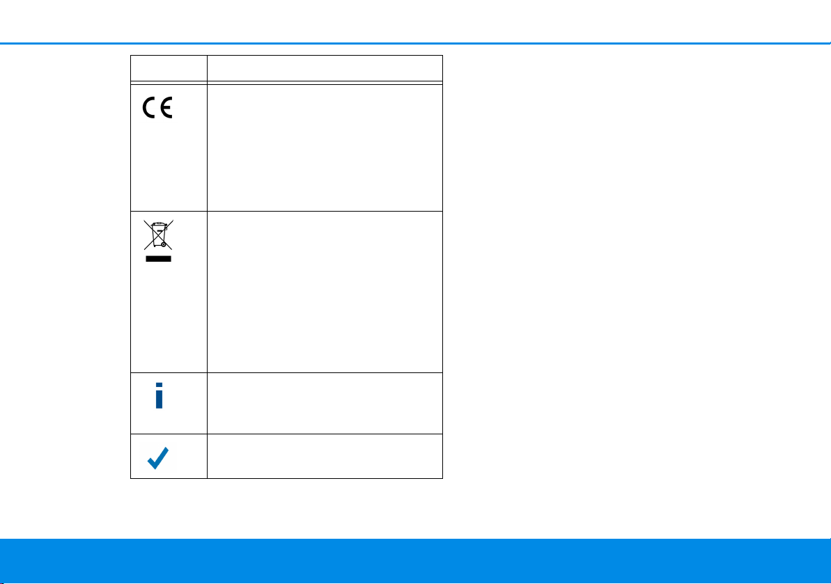
Icon Description
Very important safety symbol that
warns you of imminent electrical
voltage which if not observed can
result in serious injury or death.
An important safety symbol that
warns you of a potentially dangerous situation involving a burn hazard which can result in minor
injuries or damage to property.
An important note that should be
observed which can potentially
lead to material damages.
The device may only be used indoors in dry conditions.
devo lo Magic 1 LA N
1-1
Page 7
7 Preface
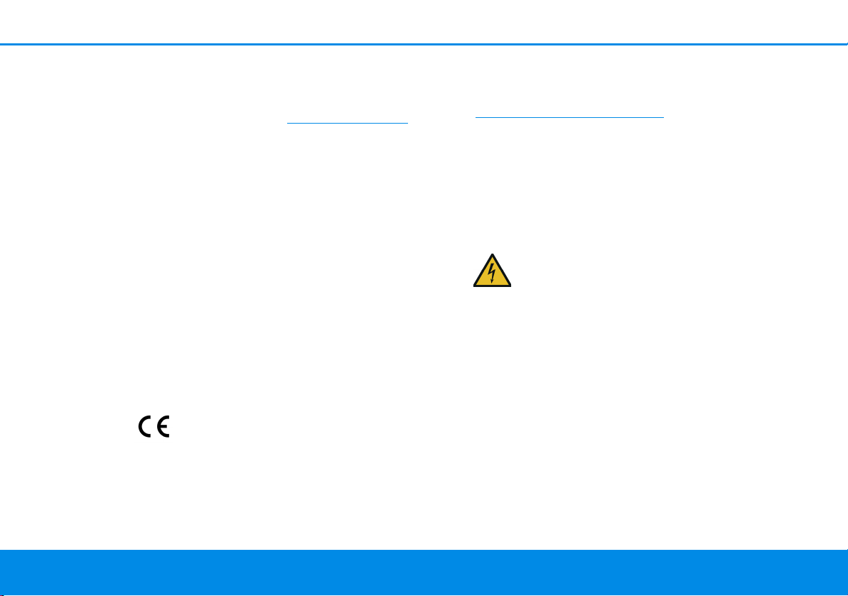
Icon Description
The manufacturer/distributing
company uses the CE marking to
declare that the product meets all
applicable European regulations
and has been subjected to the prescribed conformity assessment
procedures.
It is used to prevent the occurrence
of waste electrical and electronic
equipment and to reduce this type
of waste through reuse, recycling
and other forms of utilisation. The
European Community WEEE Directive establishes minimum standards
for handling waste electrical and
electronic equipment in the EU.
Additional information, background material and configuration
tips for your device.
Indicates a completed course of action
1.2 Intended use
Use devolo products, devolo software and the provided accessories as described to prevent damage
and injury.
Products
devolo products are communication devices designed for indoors.* Depending on the product, they
are equipped with a PLC- (PowerLine Communica-
tion) and/or a Wi-Fi module. Computers, laptops,
smartphones, tablets, smart TVs and other devices
connected this way are integrated into a home
network over the existing electrical wiring and/or
Wi-Fi without any complicated wiring. devolo devices must never be used outdoors because the
high temperature fluctuations and moisture can
damage both the product and the power line. devolo products may not be installed at a height above two metres unless an additional fas-tening
mechanism is available. The products are intended
for operation in the EU, Switzerland and Norway.
* The only exceptions are devolo outdoor products, which are
suited for the outdoor use thanks to their IP certification.
devolo Magic 1 LAN
1-1
Page 8
Preface 8
Software
devolo devices can be used only with the free,
downloadable programs approved and available
on devolo AG's website (www.devolo.com)
app stores (iOS and Google Play). Any
modifications to the product-specific firmware or
software could damage the products and, in the
worst-case scenario, render them unusable and
negatively affect conformity.
Always use the most up-to-date software version
to make sure you have the latest security functions
and device updates. The installed devolo software
notifies you automatically if a new software version is available.
Accessories
Use only the provided accessories.
and in
1.3 CE Conformity
This product complies with the technical
requirements of the directives 2014/35/
EU, 2014/30/EU, 2011/65/EU und 2009/
125/EC.
This product is designed for use in the EU,
Switzerland and Norway.
A printout of the simplified CE declaration of this
product is separately included and can also be
found under
www.devolo.com/support/ce
.
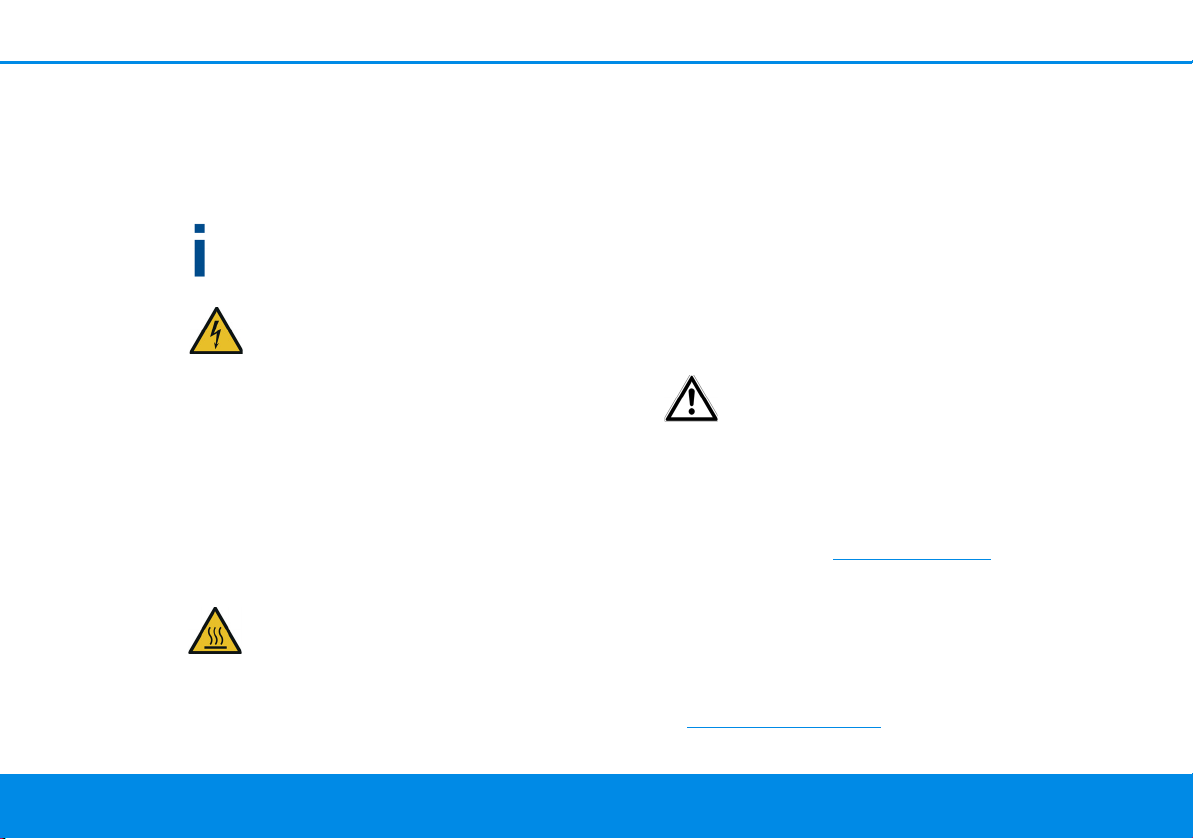
1.4 Safety notes
It is essential to have read and understood all safety and operating instructions before the devolo device is used for the first time; keep them safe for
future reference.
DANGER! Electrical shock caused by
electricity
Do not reach into the electrical socket, do
not open the device and do not insert any
objects into the electrical socket or into the
ventilation openings
Users do not need to carry out any maintenance on
devolo devices. In the event of damage, disconnect
the devolo device from the mains supply by pulling
it or its plug out of the electrical socket. Then contact qualified specialist personnel (after-sales service) exclusively. Damage is deemed to have
occurred, for example,
devo lo Magic 1 LA N
1-1
Page 9
9 Preface
b if the power plug is damaged.
b if the devolo device has been showered with
liquid (such as rain or other water).
b if the devolo device is inoperable.
b if the housing of the devolo device is damaged.
Do not plug devolo devices directly into each
other. Devices that are plugged into each other
can experience a decrease in transmission rate.
DANGER! Electric shock caused by
electricity
Device must be plugged into a power
socket with a connected earth wire
devolo devices may be operated only on a mains
power supply as described on the rating plate.
To disconnect devolo devices from the mains supply, unplug the device from the electrical socket.
The power socket and all connected network devices should be easily accessible so that you can pull
the power plug quickly if needed.
CAUTION! Heat development during operation
Certain housing components can become
very hot in certain situations. Attach device
so that it is touch-proof, observing optimal
positioning
devolo devices should only be installed at locations
that guarantee adequate ventilation. Slots and
openings on the housing are used for ventilation:
b Do not cover devolo devices during operation.
b Do not place any objects on devolo devices.
b Do not insert any objects into the openings of
devolo devices.
b devolo devices must not be placed directly
next to a naked flame (such as fire or candles).
b devolo devices must not be exposed to direct
heat radiation (e.g. radiator, direct sunlight).
CAUTION! Damage to housing from
cleaning agents containing solvents
Clean only electroless and with dry cloth
1.5 devolo on the Internet
For detailed information on our products and
devolo Magic, visit www.devolo.com
There you will find product descriptions and documentation, and also updates of devolo software
and your device's firmware.
If you have any further ideas or suggestions related
to our products, please don't hesitate to contact us
at support@devolo.com
!
.
devolo Magic 1 LAN
1-1
Page 10
Introduction 10
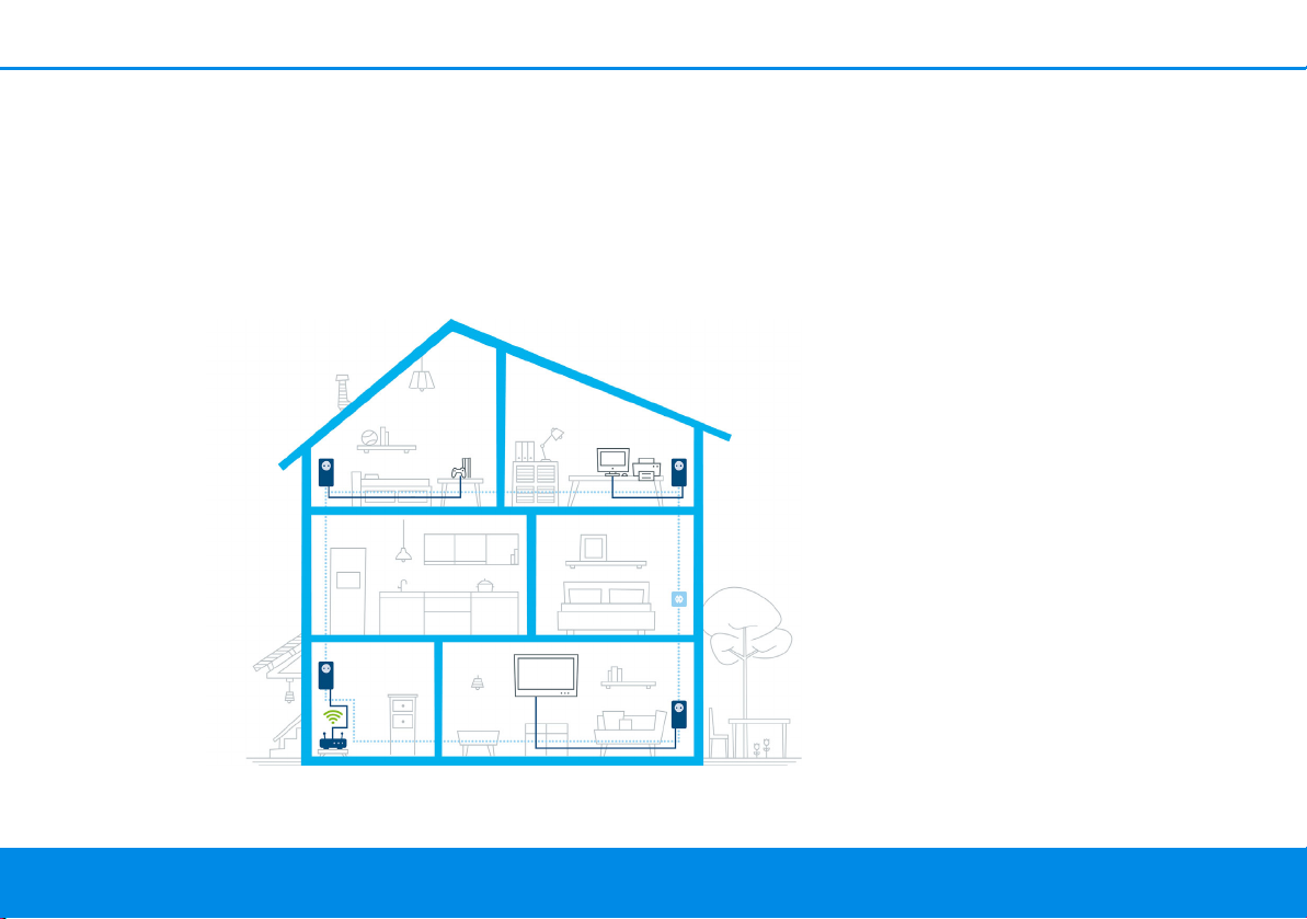
Fig. 1 devolo Magic throughout the home
2 Introduction
2.1 devolo Magic
Home is where devolo Magic is – in no time at all,
devolo Magic transforms your house or flat into a
multimedia home of the future with noticeably
higher speed, more stability and greater range,
providing the perfect Internet experience as a
result!
Be inspired by products that are astonishingly easy
to install, with impressive, innovative technology
and unbeatable performance.
devo lo Magic 1 LA N
1-1
Page 11
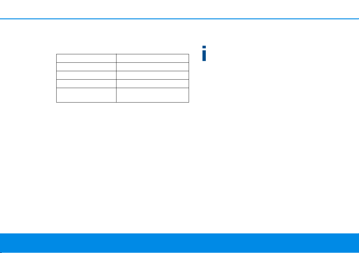
11 Introduction
The product name concept
The devolo Magic name concept has the following
structure:
Product family
Performance category
Transmission type
Number of sockets
Integrated electrical
socket
devolo Magic
1
LAN (Ethernet)
1
1 (= yes)
Be ready for the technology of the future today
devolo Magic embodies the new generation of the
tried-and-tested Powerline technology (PLC) based on the cutting-edge G.hn architecture. G.hn
was developed by the International Telecommunication Union (ITU) with ongoing development provided primarily by the HomeGrid Forum industry
association. devolo Magic products are certified
according to HomeGrid standards and are compatible with other HomeGrid-certified products.
Like the HomePlug AV technology used in established devolo dLAN devices, devolo Magic uses the
household mains supply for data transmission and
secures ideal performance and stability in locations
where network cables are not viable or desired
and/or the Wi-Fi frequently falls short due to ceilings and walls.
To set up a devolo Magic network, you need at
least two devolo Magic devices. For technical
reasons, devices from the devolo Magic series
are not compatible with dLAN devices.
2.2 Introduction to the devolo Magic adapter:
Unpack – plug in – get started and be ready for
the new generation of tried-and-tested Powerline
technology:
b Speed and stability – thanks to consistent data
transmission speed at up to 1200 Mbps over
distances of up to 400 meters, the
devolo Magic 1 LAN
ment at the highest level.
b Security – with 128-bit AES Powerline encryp-
tion
b Energy-efficiency – the integrated PowerSave
mode cuts energy consumption automatically
during low data traffic.
b A devolo Magic 1 LAN
electrical socket in your household electrical
wiring into a Gigabit LAN Internet access point.
1-1
promises entertain-
1-1
transforms any
devolo Magic 1 LAN
1-1
Page 12

Introduction 12
Fig. 2: devolo Magic 1 LAN
1-1
with country-specific
connector and power socket
b Its integrated electrical socket can be used (like
a normal wall socket) to supply power to an
additional network device or a power strip.
b The Gigabit LAN port on the
devolo Magic 1 LAN
1-1
lets you connect a stationary network device – such as a game console, television or media receiver – to your
Internet access point over the Powerline network (e.g. Internet router).
The devolo Magic 1 LAN
1-1
features
b One Gigabit network connection
b One indicator light
The LED status display can be disabled. You can
find more information about this in Chapter 4
Configuration or in the product manual for the
devolo Cockpit software available online at
www.devolo.com/cockpit
.
b One PLC/reset button (next to the network
connection)
b One integrated electrical socket
2.3 Pairing
devolo Magic adapters that are in factory default
condition, i.e. have been purchased or successfully
reset (see Chapter Resetting a devolo Magic ad-
apter or removing it from a devolo Magic network), automatically start to attempt to pair with
another devolo Magic adapter when reconnected
to the mains supply.
devo lo Magic 1 LA N
1-1
Page 13

13 Introduction
Starting up a new devolo Magic network
After plugging the devolo Magic adapters into
available power sockets, a new devolo Magic network is established automatically within 3 minutes.
Expanding an existing devolo Magic network
by adding another devolo Magic adapter
In order to use a new devolo Magic 1 LAN
1-1
in
your devolo Magic- network, first you have to
connect it to your existing devolo Magic adapters
devices as a network. This is accomplished by using
a shared password, which can be assigned in various ways:
b Using devolo Cockpit or the
devolo Home Netwok App (see Chapter 3.4
Installation of devolo software)
b Using the web interface (see Chapter 4.2.2
PLC)
b Using the PLC/reset button as described
below.
1 To do so, plug the new devolo Magic adapter
into an available power socket and, for approximately 1 second, press the PLC/reset button
on a devolo Magic adapter in your existing
devolo Magic network.
For each pairing operation, only one additional
devolo Magic adapter can be added at a time.
2 Within 3 minutes, press the PLC/reset button
on the devolo Magic adapter that you want to
add to your existing devolo Magic network.
The LED of this adapter now also flashes white.
After a short time, the flashing LED becomes a steady white light. The devolo Magic
adapter has been successfully integrated
into your existing devolo Magic network.
You can find detailed information about installing devolo Magic adapters in Chapter 3.3
Connecting the devolo Magic 1 LAN
1-1
.
Resetting a devolo Magic adapter or removing
it from a devolo Magic network
1 To remove a devolo Magic adapter from your
devolo Magic network and successfully restore
its entire configuration to the factory default
settings, press and hold the reset button longer
than 10 seconds.
2 Wait until the LED flashes white and then dis-
connect the devolo Magic adapter from the
mains supply.
devolo Magic 1 LAN
1-1
Page 14

Introduction 14
Keep in mind that all settings that have already
been made will be lost!
devo lo Magic 1 LA N
1-1
Page 15

15 Introduction
2.3.1Reading the indicator light
The integrated indicator light (LED) shows the status for the devolo Magic 1 LAN
and/or flashing:
1-1
by illuminating
devolo Magic 1 LAN
LED Flashing be-
haviour
1 Red LED Lights up for
up to 2 sec.
2 Red LED Flashes at in-
tervals of 0.5
sec. (on/off)
1-1
Meaning LED status display
(web interface*)
Start-up process Cannot be disabled
Status 1:
Cannot be disabled
The reset of the devolo Magic adapter was
successful. The PLC/reset button has been
pressed and held for 10 seconds.
Status 2:
The devolo Magic adapter (once again) has
the factory default settings. Since the last reset, no pairing with another devolo Magic
adapter has taken place.
Connect the adapter with another
devolo Magic adapter to create a fullfledged PLC network as described in Chapter 2.3 Pairing.
Page 16

Introduction 16
LED Flashing be-
Meaning LED status display
haviour
3 Red LED Lights up stea-dyStatus 1:
The other network nodes are in standby
mode and cannot currently be accessed over
the mains supply. The PLC LEDs of the other
devolo Magic adapters flash white only for a
short time.
Status 2:
The connection to the other network nodes
has been interrupted. There may be electromagnetic or radio frequency interference on
the power line. In this case, put the
devolo Magic adapters closer to each other
or try to shut off the source of interference.
4Red and
white
LED
Flashes at intervals of 0.1
sec. red/2 sec.
Data transmission rate not in optimum
range **
white
(web interface*)
Can be disabled
Can be disabled
devo lo Magic 1 LA N
1-1
Page 17

17 Introduction
LED Flashing be-
haviour
5White
LED
Status 1:
Flashes at intervals of
0.5 sec.
(on/off)
Status 2:
Flashes at intervals of
1 sec.
(on/off)
6White
LED
7White
LED
Lights up steady
Flashes at intervals of
0.1 sec. on /
5sec.off
8Red and
white
LED
Flashes at intervals of
0.5 sec. red/
0.5 sec. white
Meaning LED status display
(web interface*)
Status 1:
Cannot be disabled
This devolo Magic adapter is in pairing
mode and the system is searching for new
devolo Magic adapters.
Status 2:
Someone has triggered the "Identify device"
function on the web interface or in the
devolo Home Netwok App. This function
identifies the devolo Magic adapter being
sought.
The devolo Magic connection does not have
Can be disabled
any issues and the devolo Magic adapter is
ready to operate.
The devolo Magic adapter is in standby mo-
Can be disabled
de.***
The devolo Magic adapter is carrying out a
Cannot be disabled
firmware update.
devolo Magic 1 LAN
1-1
Page 18

Introduction 18
* Information about the web interface can be
found in Chapter 4 Configuration.
** Information on improving the transmission rate
can be found in Chapter 5.2 Bandwidth optimi-
zation.
***A devolo Magic adapter switches to standby
mode after approximately 10 minutes if no active
network device (e.g. computer) is connected to the
network interface. In this mode, the devolo Magic
adapter cannot be accessed over the electrical wiring. As soon as the network device (e.g. computer)
connected to the network interface is switched on
again, your devolo Magic adapter can also be accessed over the electrical wiring again.
Check whether the adapter is connected to the
mains supply correctly and whether the pairing
operation has been carried out successfully. For
more information about this, refer to 3.3
Connecting the devolo Magic 1 LAN
1-1
.
2.3.2Network connection
You can use the network connection on the
devolo Magic adapter to connect it to a PC or television using a standard network cable.
2.3.3Integrated electrical socket
Always use the integrated electrical socket on the
devolo Magic adapter when connecting other
consumers to the mains supply. In particular,
electronic devices with mains adapter can negatively affect PLC performance.
The integrated mains filter in the devolo Magic adapter filters any such external interference and reduces any impairment of PLC performance.
devo lo Magic 1 LA N
1-1
Page 19

19 Initial use
3Initial use
This chapter tells you everything you need to know
to set up and use your devolo Magic 1 LAN
describe how to connect the adapter and briefly
describe the devolo software.
3.1 Package contents
Please ensure that the delivery is complete before
beginning with the installation of your
devolo Magic 1 LAN
b Starter Kit:
a 2 devolo Magic 1 LAN
a 2 network cables
a Hard copy of installation guide
a Hard copy security flyer
a CE declaration
or
b Extension:
a 1 devolo Magic 1 LAN
a 1 Network cable
a Hard copy of installation guide
a Hard copy security flyer
a CE declaration
1-1
:
1-1
1-1
1-1
. We
devolo AG reserves the right to change the package contents without prior notice.
3.2 System requirements
b Operating systems supported by devolo
Cockpit:
a from Windows 7 (32-bit/64-bit),
a from Ubuntu 13.10 (32-bit/64-bit),
a from Mac (OS X 10.9)
b Network connection
Please note that your computer or other device
must have a network card or network adapter
with a network interface.
To set up a devolo Magic network, you need
at least two devolo Magic adapters.
devolo Magic 1 LAN
1-1
Page 20

Initial use 20
3.3 Connecting the
devolo Magic 1 LAN
CAUTION! Damage to the device caused
by ambient conditions
Only use device indoors in dry conditions
In the following sections we describe how to
connect the devolo Magic 1 LAN
it into a network. We clarify the exact procedures
based on potential network scenarios.
For the permitted voltage range for operating the device
and the power consumption, refer to the type plate on the
rear of the device. For additional technical information on
our products, refer to the product area at
www.devolo.com
3.3.1Starter Kit – Automatic set-up for a
new devolo Magic network
1 Connect one devolo Magic 1 LAN
Internet access device's network connection
(e.g. your Internet router).
2 Connect the other devolo Magic 1 LAN
the network connection of your computer or
another network device using a network cable.
.
1-1
1-1
and integrate
1-1
to your
1-1
to
CAUTION! Tripping hazard
Lay the network cable in a barrier-free
manner and ensure that the electrical
socket and the connected network devices are easily accessible
3 Plug both devolo Magic adapters into available
power sockets within 3 minutes. As soon as the
LEDs on both adapters flash white at regular
intervals of 0.5 sec., they are ready to operate
and automatically start the process of establishing an encrypted connection to each other
(see Chapter 2.3.1 Reading the indicator
light).
If the LEDs on both devolo Magic adapters
light up in white, then your
devolo Magic network has been set up according to your individual specifications
and is protected from unauthorised access.
devo lo Magic 1 LA N
1-1
Page 21

21 Initial use
3.3.2Addition – Expanding an existing
network by adding another
devolo Magic adapter
Before you can use the devolo Magic 1 LAN
your devolo Magic network, first you have to
connect it to your existing devolo Magic adapters
as a network. This is accomplished by using a
shared password.
1 Connect the devolo Magic 1 LAN
work connection of your computer or another
network device using a network cable.
2 Plug the devolo Magic 1 LAN
ble power socket. As soon as the LED flashes
white at regular intervals of 0.5 seconds, the
adapter is ready to operate but not yet integrated into a devolo Magic network (see Chapter
2.3.1 Reading the indicator light).
3 Within 3 minutes, press the PLC/reset button
on a devolo Magic adapter in your existing
devolo Magic network for approximately 1 sec.
If the LEDs light up white on both
devolo Magic adapters, the new adapter
has been successfully integrated into your
existing devolo Magic network.
1-1
1-1
into an availa-
1-1
in
to the net-
For each pairing operation, only one additional
adapter can be added at a time.
3.3.3Changing the network password
A network password can also be changed in the
following ways:
b Using the web interface of the devolo Magic
adapter (see Chapter 4.2.2 PLC)
or
b Using devolo Cockpit or the
devolo Home Network App. For more infor-
mation, refer to the following chapter.
3.4 Installation of devolo software
Installing devolo Cockpit software
devolo Cockpit finds all accessible devolo Magic
adapters in your devolo Magic network, displays
information about these devices and encrypts your
devolo Magic network individually. You can use
the software to navigate to the integrated web interface.
Operating systems supported by devolo Cockpit
(Version 5.0 or later):
devolo Magic 1 LAN
1-1
Page 22

Initial use 22
b from Windows 7 (32-bit/64-bit) or later,
b from Ubuntu 13.10 (32-bit/64-bit),
b from Mac (OS X 10.9)
You can find the product manual, software and
additional information on devolo Cockpit online at www.devolo.com/cockpit
Downloading the devolo Home Network App
The devolo Home Network App is devolo's free
app also for checking and configuring Wi-Fi, Magic
and LAN connections for the devolo Magic adapter
(using a smartphone or tablet). The smartphone or
tablet connects to the devolo Magic adapter at
home over Wi-Fi.
1 Download the devolo Home Network App to
your smartphone or tablet computer from the
corresponding store.
2 The devolo Home Network App is placed in
your smartphone's or tablet's app list as usual.
Tapping on the devolo Home Network App
icon brings you to the start menu.
You can find more information about the
devolo Home Network App online at
www.devolo.com/devolo-app
.
.
3.5 Removing the devolo Magic adapter from a network
To remove a devolo Magic adapter from your network and successfully restore its entire configuration to the factory default settings, press the PLC/
reset button longer than 10 seconds. Wait until the
LED flashes white and then disconnect the adapter
from the mains supply.
Keep in mind that all settings that have already
been made will be lost!
To integrate the mains supply into another network, proceed as described in Chapter 3.3.2 Addi-
tion – Expanding an existing network by adding
another devolo Magic adapter.
devo lo Magic 1 LA N
1-1
Page 23

23 Configuration
4 Configuration
The devolo Magic 1 LAN
terface that can be called up using a standard web
browser. Here, you can read out device information and configure some settings for operating the
devolo Magic adapter.
4.1 Calling up the built-in web interface
You can access the built-in web interface for the
devolo Magic 1 LAN
b Using the devolo Home Network App on your
smartphone or tablet, you can access the web
interface of the devolo Magic adapter by going
to the devolo Home Network App overview
page and tapping on the gear/arrow.
You can find more information on
devolo Home Network App in Chapter 3.4 In-
stallation of devolo software.
b Using the devolo Cockpit software under
Start, you can access the web interface of the
devolo Magic adapter by clicking on the tab for
the device's configuration page in
devolo Magic 1 LAN
1-1
has a built-in web in-
1-1
in different ways:
1-1
.
Then the program determines the current IP
address and starts the configuration in the web
browser.
You can find more information on devolo software in
Chapter 3.4 Installation of devolo software.
4.2 Menu description
All menu functions are described in the corresponding interface as well as in the associated chapter
in the manual. The sequence of the description in
the manual follows the structure of the menu.
devolo Magic 1 LAN
1-1
Page 24

Configuration 24
Fig. 3: Menu
The 5 central web interface areas are displayed at
the edge of the screen. Click a menu to switch directly to that menu:
Save
Confirm with OK to save the settings for the respective web interface area.
Default settings
Some fields contain default settings which ensure
the greatest amount of compatibility and ease of
use.
Default settings are identified with an * in dropdown menus. Default settings can of course be replaced with customised information.
4.2.1Overview
In the Overview area, you will find information on
hardware and software for the devolo Magic adapter and network details.
devo lo Magic 1 LA N
1-1
Page 25

25 Configuration
Fig. 4: Overview
PLC
The table lists all available and connected
devolo Magic adapters in your network along with
displaying some device details.
You can find more detailed information on the
displayed device details in Chapter 4.2.2 PLC.
System
Name: Device name
MT number: Device type number
Serial number: Device serial number
MAC address: MAC address of the device
Software information
FW version: Firmware version of the device
System uptime: Operating time since the last re-
start
LAN
LAN port 1: Network connection; if a connection
has been detected, the speed (10/100/1000 Mbps) and the mode (half/full duplex) are specified;
otherwise, the status "unconnected" is specified.
devolo Magic 1 LAN
DHCP: Display indicating whether DHCP is switched on or switched off
1-1
Page 26

Configuration 26
Fig. 5 PLC
IPv4 address: IPv4 address in use
IPv4 netmask: IPv4 network mask in use
IPv4 gateway: IPv4 gateway in use
DNSv4: DNSv4 server in use
IPv6 link-local address: Link-local address in use
IPv6 SLAAC address: SLAAC address in use
DNSv6: DNSv6 server in use
You can find more detailed information on the
displayed network details in Chapter 4.2.3
LAN.
4.2.2PLC
In the PLC area, you will find functions and information on the topic of Powerline and adapter pairing.
devo lo Magic 1 LA N
1-1
Page 27

27 Configuration
In order to use a new devolo Magic 1 LAN
1-1
in
your devolo Magic network, first you have to
connect it to your existing devolo Magic adapters
devices as a network. This is accomplished by using
a shared password. This can be assigned in different ways:
b Using devolo Cockpit or the
devolo Home Network App (see Chapter 3.4
Installation of devolo software),
b Only using the PLC/reset button (see Chapter
2.3 Pairing and 3.3 Connecting the
devolo Magic 1 LAN
1-1
)
b Using the web interface, in the PLC menu; as
described below:
Pairing – Using custom password
You can also assign your network a custom PLC
password you pick yourself. Enter this password for
each devolo Magic adapter in the PLC password
field and confirm your entry with OK.
Note that the custom password is not assigned
to the whole PLC network automatically. Instead, you must assign it separately to each of
your devolo Magic adapters.
Unpairing – Resetting or removing an adapter
from a network
1 To remove a devolo Magic adapter from your
devolo Magic network, click Unpair.
Pairing – Using physical button and on-screen
button
1 First, press the PLC/reset button on a
2 Then, click PAIR to start the pairing operation.
As soon as the new devolo Magic adapter is integrated into your existing network, it appears in a
list of available and established connections (see
Chapter PLC connections).
devolo Magic 1 LAN
2 Wait until the LED flashes red and then dis-
connect the devolo Magic adapter from the
mains supply.
devolo Magic adapter in your existing network.
This may take some time.
1-1
Page 28

Configuration 28
Compatibility mode
Using as VDSL connection may negatively impact
the performance of the bandwidth connection.
Select from among the following settings in order
to mitigate any potential negative effects.
Operating mode:
b SISO
Signal transmission profiles:
b Full power
b VDSL 17a
b VDSL 35b
Get in touch with your internet provider to find
out which signal transmission profile is the best
option for your internet connection.
The SISO operating mode and the VDSL 17a signal
transmission profile are configured by default.
PLC connections
The table lists all available and connected
devolo Magic adapters for your network along
with displaying the following details:
Device ID: Device ID* (number) of the respective
devolo Magic adapter in the devolo Magic network
* indicates the local devolo Magic adapter
MAC address: MAC address of the respective
devolo Magic adapter
Transmit (Mbps): Data transmission rate
Receive (Mbps): Data reception rate
devolo Magic 1 LAN
1-1
Page 29

29 Configuration
Fig. 6: LAN
4.2.3LAN
You make changes to the network settings in the
LAN area.
You can access the web interface for the
1-1
devolo Magic 1 LAN
using its current IP address.
This may be an IPv4 and/or IPv6 address, which is
either entered manually as a static address or automatically retrieved from a DHCP server.
IPv4 configuration
In the factory default settings, only the DHCP
enabled option for IPv4 is enabled. This means
that the IPv4 address is retrieved axiomatically
from a DHCP server. The currently assigned network data is visible (greyed out).
If a DHCP server is already present on the network
for giving out IP addresses (e.g. your Internet router), you should enable the DHCP enabled option
so that the devolo Magic 1 LAN
1-1
automatically
receives an address from it.
If you want to assign a static IP address, make
entries accordingly for the IPv4 address, IPv4 net-
mask, Default gateway and DNS fields.
Confirm your settings with OK.
Then, restart the devolo Magic adapter (see Chapter 4.2.5 Reset) to ensure that your changes take
effect.
devolo Magic 1 LAN
1-1
Page 30

Configuration 30
IPv6 configuration
If you want automatic IP address assignment and
there is already a DHCP server present on the network for giving out IP addresses (e.g. your Internet
router), enable the DHCPv6 enabled option to ensure that the devolo Magic 1 LAN
1-1
automatically
receives an address from this device.
If you want to assign a static IP address, make
entries accordingly for the IPv6 address, IPv6 pre-
fix, Default gateway and DNS fields.
IPv6 link-local address: In the case of IPv6, the
devolo Magic adapter always has a fixed address
which can be used to access it within the
connected Ethernet or PLC network segment. This
link-local address is derived from the Ethernet MAC
address.
IPv6 link-local prefix: Corresponding format prefix for link-local addresses
IPv6 SLAAC address: Using the SLAAC method
(Stateless Address Autoconfiguration), the
devolo Magic 1 LAN
1-1
automatically generates
an IP address by itself.
Then, restart the devolo Magic adapter (see Chapter 4.2.5 Reset) to ensure that your changes take
effect.
4.2.4System
In the System area, you can configure the settings
for security and other devolo Magic adapter device
functions.
IPv6 SLAAC prefix: Corresponding format prefix
for SLAAC addresses
Confirm your settings with OK.
devo lo Magic 1 LA N
1-1
Page 31

31 Configuration
Fig. 7: System
Identify device
The devolo Magic adapter can be located using the
Identify device function. Click Identify to make
the white LED for the corresponding adapter flash
for 2 minutes to make it easier to identify by sight.
LEDs
Enable the LEDs reduced option if the LEDs on the
devolo Magic adapter are intended to be switched
off for normal operation. An error status is indicated by corresponding flashing behaviour regardless of this setting (see Chapter 2.3.1 Reading the
indicator light).
devolo Magic 1 LAN
1-1
In System, you can enable Powersaving mode and
Standby mode on the devolo Magic 1 LAN
1-1
.
If Powersaving mode has been enabled, the
devolo Magic 1 LAN
1-1
switches to Powersave
mode automatically whenever reduced data transmission over ethernet is detected.
The latency (time for transmitting a data
packet) may be negatively affected if very slow
data transmission is detected.
If Standby mode is enabled, the
devolo Magic 1 LAN
1-1
automatically switches to
Standby mode if no ethernet connection has been
Page 32

Configuration 32
enabled, i.e. if no network device (e.g. computer) is
switched on and connected to the network interface and if Wi-Fi is disabled.
In this mode, the devolo Magic 1 LAN
1-1
is not
accessible over the Powerline network. As soon as
the network device (e.g. computer) connected to
the network interface is switched on again, your
adapter can also be accessed over the electrical
wiring again.
Powersave mode is disabled in the
devolo Magic 1 LAN
1-1
factory default settings.
Standby mode is enabled in the
devolo Magic 1 LAN
1-1
factory default condition.
For information on the LED behaviour of the
devolo Magic adapter in standby mode, refer to
Chapter 2.3.1 Reading the indicator light.
Password
You can set a login password for access to the web
interface.
By default, the built-in web interface of the
devolo Magic 1 LAN
1-1
is not protected by a
password. We recommend assigning a password
when the installation of the devolo Magic 1 LAN
1
is complete to protect it against tampering by
third parties.
To do so, enter the desired new password twice.
Now the web interface is protected against unauthorised access with your custom password!
Firmware upgrade
The firmware of the devolo Magic 1 LAN
1-1
includes the software for operating the device. If
necessary, devolo offers new versions on the
Internet as a file download, for example to modify
existing functions.
1 To bring the firmware up to the latest version,
first go to the devolo website,
www.devolo.com
ate file for the devolo Magic 1 LAN
, and download the appropri-
1-1
to your
computer.
1-
devo lo Magic 1 LA N
1-1
Page 33

33 Configuration
Fig. 8: Restart and reset
2 Then, navigate to the System d Firmware
upgrade area. Click Choose… and select the
downloaded file.
3 Confirm the update procedure with OK. After a
successful update, the devolo Magic 1 LAN
1-1
restarts automatically.
Ensure that the update procedure is not
interrupted.
4.2.5Reset
Here, restart the devolo Magic adapter and/or restore it to the factory default settings.
Restart device
To restart a devolo Magic adapter, click Restart.
Factory reset
1 To remove a devolo Magic adapter from your
devolo Magic network and successfully restore
its entire configuration to the factory default
settings, click Reset.
2 Wait until the LED flashes white and then dis-
connect the devolo Magic adapter from the
mains supply.
devolo Magic 1 LAN
Keep in mind that all settings that have already
been made will be lost!
1-1
Page 34

Appendix 34
Fig. 9: Bandwith optimization
5 Appendix
5.1 Technical specifications
Security 128 Bit AES
Device port 1x RJ45
(Gigabit Ethernet port)
Power consumption Maximum: 3.2 W
Typical: 2.8 W
Stand-by: 0.5 W
Power supply internal
196-250 V AC
50 Hz
Temperature
(Storage/Operating
Dimensions (in mm,
without plug)
Ambient conditions 10-90% Humidity,
Certifications CE
-25°C to 70 °C / 0°C to
40°C
133x66x42 (HxWxD)
non-condensing
5.2 Bandwidth optimization
To significantly improve the transmission capacity
of the network, we recommend that you comply
with the following "connection rules":
b Plug the devolo Magic 1 LAN
wall socket. Avoid using power strips. This may
impair the transmission of the PLC signals.
b If there are several sockets in the wall directly
next to each other, they behave like a power
strip. Individual sockets are optimal.
1-1
directly into a
devo lo Magic 1 LA N
1-1
Page 35

35 Appendix
5.3 Disposal of old devices
To be used in the countries of the European Union
and other European countries with a separate collecting system:
The icon with crossed-out wastebasket on
the device means that this product is an
electrical or electronic device that falls
within the scope of application of the European Community WEEE Directive. These types of devices may no longer be
disposed of with household waste. Rather
they can be given to a municipal collection point free of charge. Contact your municipal government to find out the
address and hours of the nearest collection point.
5.4 Warranty conditions
If your devolo device is found to be defective during initial installation or within the warranty period, please contact the vendor who sold you the
product. The vendor will take care of the repair or
warranty claim for you. The complete warranty
conditions can be found at
www.devolo.com/warranty
.
devolo Magic 1 LAN
1-1
Page 36

Index
A
Adapter equipment 12
C
CE 8
CE declaration 8
Changing/assigning the network password 13, 21
D
devolo app 22
devolo Cockpit 21
devolo Magic 10
devolo software 21
DHCP server 29, 30
Disposal of old devices 35
E
Expanding an existing devolo Magic network 13
F
Factory default settings 13, 22, 33
Factory reset 13, 33
I
Integrated electrical socket 18
Intended use 7
IP address 29
IPv4 29
IPv6 30
L
LAN (network connection) 18
LED status display 12, 15
N
Network connection 18
P
Package contents 19
Pairing 12
PLC 11, 12
Powerline 11
Product name concept 11
R
Reset 13, 22, 33
Resetting a devolo Magic adapter 13
Restart 33
S
Safety notes 8
Starting up a new devolo Magic network 13
devolo Magic 1 LAN
1-1
 Loading...