

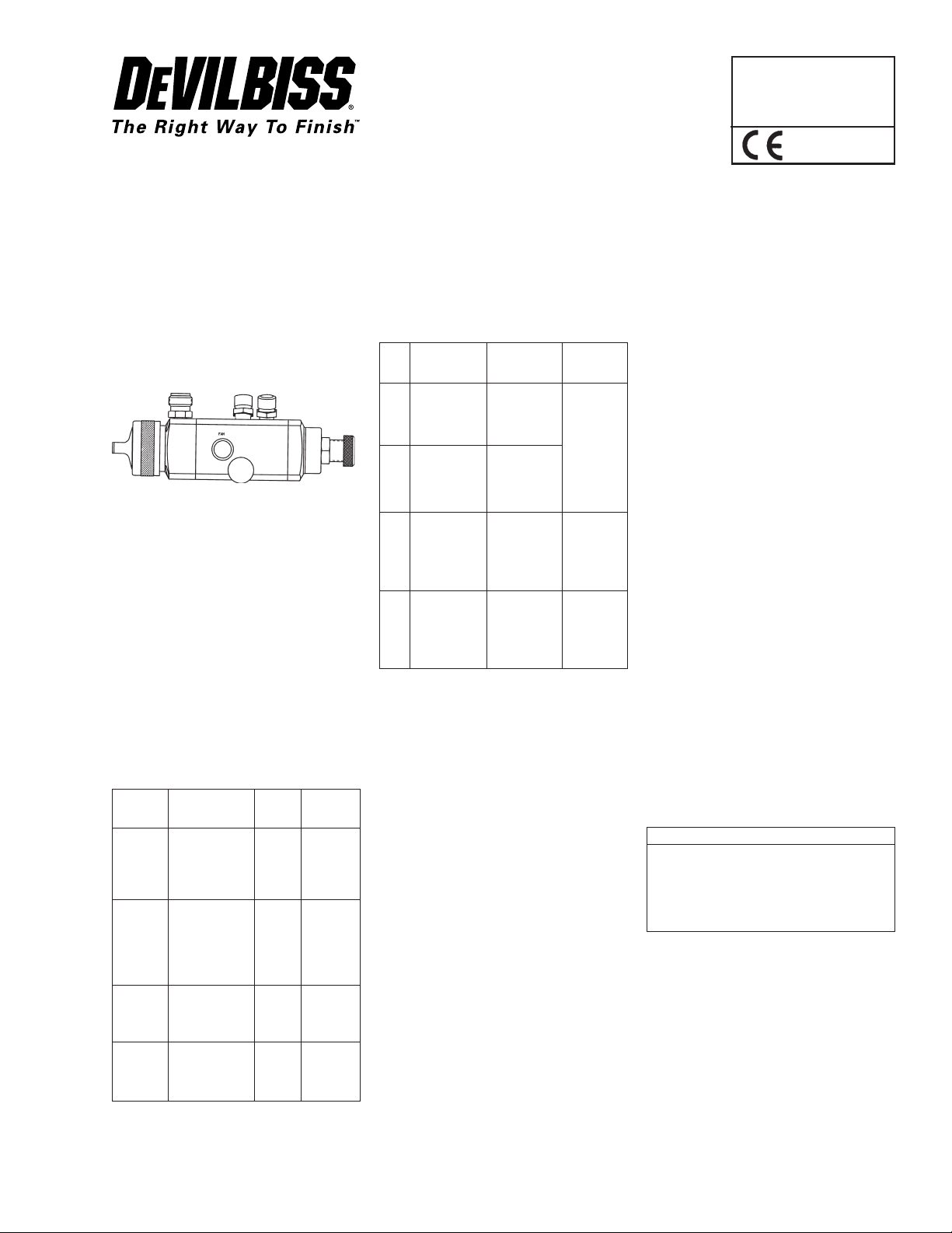
DeVillbiss Air Power Company AGXV-540, AGXV-541, AGXV-542, AGXV-543 User Manual
SERVICE BULLETIN
SB-2-628-K
Replaces SB-2-628-J
Repair Kit KK-4992-1
AGXV-540, AGXV-541, AGXV-542 & AGXV-543
AUTOMATIC SPRAY GUNS
IMPORTANT: Before using this equipment, read SAFETY PRECAUTIONS
starting on page 2.
DESCRIPTION
The AGXV high volume, low pressure spray gun
(spray pistol) is used on automatic and semiautomatic machines where mass production
spraying is necessary, or hand spraying is not
accurate enough. Models and application information follows. All models are designed to provide maximum transfer efficiency by limiting air
cap pressure to 10 psi (0.7 bar) (in the U.S., this
complies with rules issued by SCAQMD and
other air quality authorities). Air cap pressure
can be measured with an optional air cap test kit.
See "ACCESSORIES" on Page 8.
CHART 1 MODELS
Model No. HVLP Fluid
(Available Typical Air Cap Tip/Needle
Tip Sizes) Applications Used Construction
AGXV-540 Most common 28 or 33A 400 Gr. S/S
(E, FF, FX) finishing materials
AGXV-541 High solids (low 46MP or 400 Gr. S/S
(D, E, FF, VOC's) coatings 83MP
FX) which are difficult
AGXV-542 Waterbornes and 28 or 33A 303 Gr. S/S,
(FF, FX) other corrosive Poly.
AGXV-543 Same as AGXV- 46MP 303 Gr. S/S,
(FF, FX) 541 except for Poly.
including some
waterborne and
chlorinated.
to atomize with
HVLP, or high
flow rates.
materials (below
7pH)
more corrosive materials (below 7pH)
CHART 2 AIR CAPS – PATTERNS –
APPLICATION
Air Complete *Typical
Cap Air Cap Pattern Size Typical
No. No. and Shape Application
28 JGHV-101-28 11" (280 mm)
33A JGHV-101-33A 9" (229 mm) (360 cc)
46MP JGHV-101-46MP 11" (280 mm) Low VOC
83MP JGHV-101-83MP 13" (330 mm) Low VOC
* Actual pattern length dependent upon fluid tip (nozzle) ID,
coating material flow rate, air pressure and fan pressure.
long, straight Most comsided, similar to mon finishing
704 air cap. materials, up
to 12 oz./min.
long, tapered
ends, similar to
30 air cap.
long, straight materials, 12
sided, similar to to 16 oz./min.
704 air cap. (360 to
480 cc)
long, straight materials,
sided similar to 17 oz./min.
765 air cap. (510 cc) and
above.
Most finishing materials can be atomized with
either the 28 or 33A air caps. The 28 or 33A caps
should be used where possible as they consume less air volume (CFM) and have slightly
better transfer efficiency than the 46 MP or
83MP air caps. However, more difficult to atomize materials (i.e. low VOC's) or high flow applications over 12 oz./min. (360 cc/min.), are ideal
for the 46 MP maximum performer air cap, fluid
tip and baffle combination. Also available is the
83MP (maximum performer) for even higher
flows 17 oz./min. (510 cc/min.) and above and
higher viscosities. Refer to the air cap chart for
more information.
Note
This gun may be used with chlorinated
solvents. Aluminum is not used in fluid
passages. If using chlorinated solvents,
make sure all other fluid handling components are also compatible.
A list of materials used in the construction
of this equipment is available upon request.
SPECIFICATIONS
P1 – Maximum Inlet Pressure – 100 PSI (7 bar)
P2 – Maximum Fluid Pressure – 100 psi (7 bar)
P3 – Cylinder Air Pressure
– Min. **50 psi (3.5 bar)
– Max. 100 psi (7 bar)
Weight without mounting stud – 26 oz. (738 g)
Weight with mounting stud – 30.5 oz. (865 g)
Mounting stud diameter – 3/4" (19 mm)
Wetted Parts – 300 and 400 S/S, Teflon, Poly.
(See Chart 2 for tip/needle information)
Hose Connections –
Fluid Inlet – 3/8" NPS(M)
Cylinder Air – 1/4" NPS(M)
Atomization Air – 1/4" NPS(M)
Note
For HVLP operation (max. 10 psi, - 0.7 bar
cap pressure), do not exceed the air inlet
pressure given below.
PSI (bar) Cap No.
57 (4) 83MP
50 (3.4) 46MP
45 (3.1) 33A
38 (2.6) 28
** For installations where 50 psi (3.4 bar) cylinder air is not
available, the inner (red) piston spring can be removed
which lowers the minimum cylinder air to approximately 37 psi (2.5 bar). Refer to "OPERATION", Pg. 4
FLUID TIP (NOZZLE) ORIFICE SIZES
Inch mm
D .086" 2.2
E .070" 1.8
FF .055" 1.4
FX .042" 1.1
G 0.028 .7
PAGE 2 SB-2-628-K
SAFETY PRECAUTIONS
This manual contains important information that ALL users should know and understand BEFORE using the equipment. This
information relates to USER SAFETY and PREVENTING EQUIPMENT PROBLEMS. To help you recognize this information, we use
the following terms to draw your attention to certain equipment labels and portions of this manual. Pay special attention to any
label or information that is highlighted by one of these terms:
Important information to alert you to a situation that might cause
serious injury or loss of life if instructions are not followed.
Note
Important information that tells how to prevent
damage to equipment.
The following hazards may occur during the normal use of this equipment. Please read the following chart.
Information that you should pay special attention to.
HAZARD CAUSE SAFEGUARDS
Fire
Inhaling Toxic Substances 1. Follow the requirements of the Material Safety Data
Explosion Hazard –
Incompatible Materials
Solvents and coatings can be
highly flammable or combustible, especially when sprayed.
Certain materials may be harmful if inhaled, or if there is contact
with the skin.
Halogenated hydocarbon solvents- for example: methylene
chloride and 1,1,1,- Trichloroethane are not chemically compatible with the aluminum that might
be used in many system components. The chemical reaction
caused by these solvents reacting with aluminum can become
violent and lead to an equipment
explosion.
1. Adequate exhaust must be provided to keep the air free
of accumulations of flammable vapors.
2. Smoking must never be allowed in spray area.
3. Fire extinguishing equipment must be present in the
spray area.
4. Static discharges must be prevented. Ground (earth) all
conductive objects in the spray area, such as a cleaning
solvent bucket, fire extinguisher, etc.
5. When using solvents for cleaning:
•Those used for equipment flushing must have a flash
point equal to or greater than that of the coating.
•Those used for general cleaning must have flash points
above 100°F (37.8°C).
Sheet supplied by coating material manufacturer.
2. Adequate exhaust must be provided to keep the air free
of accumulations of toxic materials.
3. Use a mask or respirator whenever there is a chance of
inhaling sprayed materials. The mask must be compatible with the material being sprayed and its concentration. Equipment must be as prescribed by an industrial
hygienist or safety expert, and be NIOSH approved.
The AGXV spray gun (spray pistol) can be used with these
solvents. However, aluminum is widely used in other spray
application equipment – such as material pumps, cups, regulators, valves, etc. Check all other equipment items before
use and make sure they can also be used safely with these
solvents. Read the label or data sheet for the material you
intend to spray. If in doubt as to whether or not a coating or
cleaning material is compatible contact your material supplier.
General Safety Improper operation or mainte-
nance may create a hazard.
Operators should be given adequate training in the safe use
and maintenance of the equipment (in accordance with the
requirements of NFPA-33, Chapter 15 in U.S.). Users must
comply with all local and national codes of practice and
insurance company requirements governing ventilation, fire
precautions, operation, maintenance and housekeeping (in
the U.S., these are OSHA Sections 1910.94 and 1910.107 and
NFPA-33).
SAFETY PRECAUTIONS (Cont'd)
HAZARD CAUSE SAFEGUARDS
SB-2-628-K PAGE 3
Noise Levels – Ear Injury
Solvent Spray
Misuse:
• All spray guns (spray pistols) project particles at high velocity and must never be aimed at any part of the body.
• Never exceed the recommended safe working pressures for any of the equipment used.
• The fitting of non-recommended or non-original accessories or spare parts may create hazardous conditions.
• Before dismantling the equipment for cleaning or maintenance all pressure, air and materials, must be isolated and released.
The disposal of waste materials must be carried out in an approved manner. Burning may generate toxic fumes. The removal or waste
solvents and coating materials should be carried out by an authorized local waste disposal service.
A continuous A-weighted sound
pressure level of this spray gun
(spray pistol) may exceed 85
dB(A) depending on the air cap/
fluid head setup being used.
Sound levels are measured using an impulse sound level meter
and analyzer, when the gun is
being used in a normal spraying
application.
solvents can be forcefully expelled from fluid and air passages. Some solvents can cause
eye injury.
Always wear ear protection when using the gun.
Details of actual noise levels produced by the various air cap/
fluid head setups are available upon request.
Wear eye protection.During cleaning and flushing,
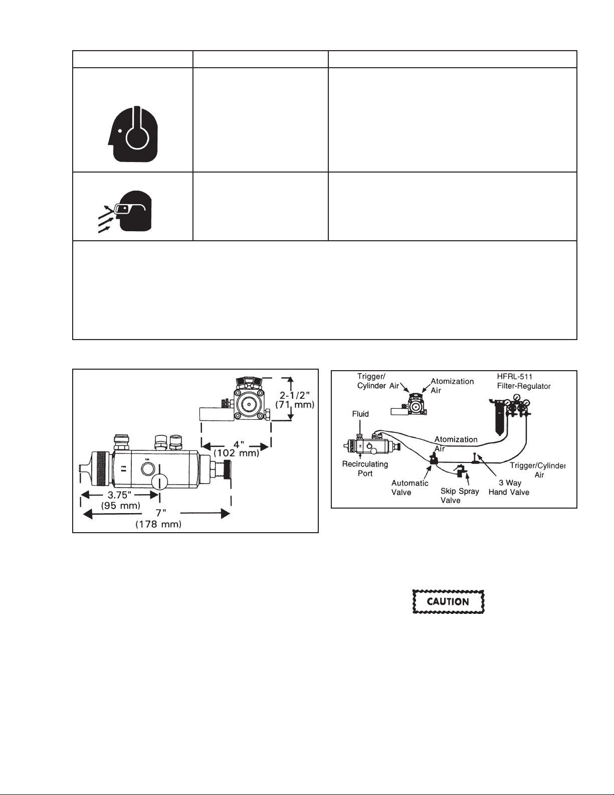
FIGURE 2 TYPICAL INSTALLATIONFIGURE 1 DIMENSIONS
INSTALLATION
Mount the gun with the stud (13) or on a 5/16" dia. rod tightening
adequately with the 1/4-28 X 1/4" set screws (Ref. 24). See "ACCESSORIES" for mounting clamps.
Note
If replacing the atomization air connection (15) with an
elbow type connection, be aware of a possible air flow
(CFM) limitation. A 1/4" (6.4 mm) I.D. 90° elbow will only
pass 20 CFM @ 40 psi (566 l/min. 2.7 bar). Some air caps
require more than 20 CFM (566 l/min.). Spray performance
could be affected.
Attach the trigger/cylinder air hose and the atomization air hose to
the connections as indicated by the markings on the gun body. The
air supply should be filtered and regulated. Attach the material
hose to the fluid inlet on the gun body. Fluid can be recirculated by
installing a fluid fitting (AGX-415) (order separately) at the recirculating port. See Caution below.
The fluid inlet and recirculating ports have a tapered
seating surface intended for use with the AGX-415 fitting. Do not substitute other fittings as fluid leakage will
occur.
 Loading...