

Page 1
SERVICE MANUAL
Repair Kit KK-5007
■
TLC-555 & TGC-545
DRIP FREE SUCTION CUPS
Important: Before using this equipment, read all safety
precautions and instructions. Keep for future use.
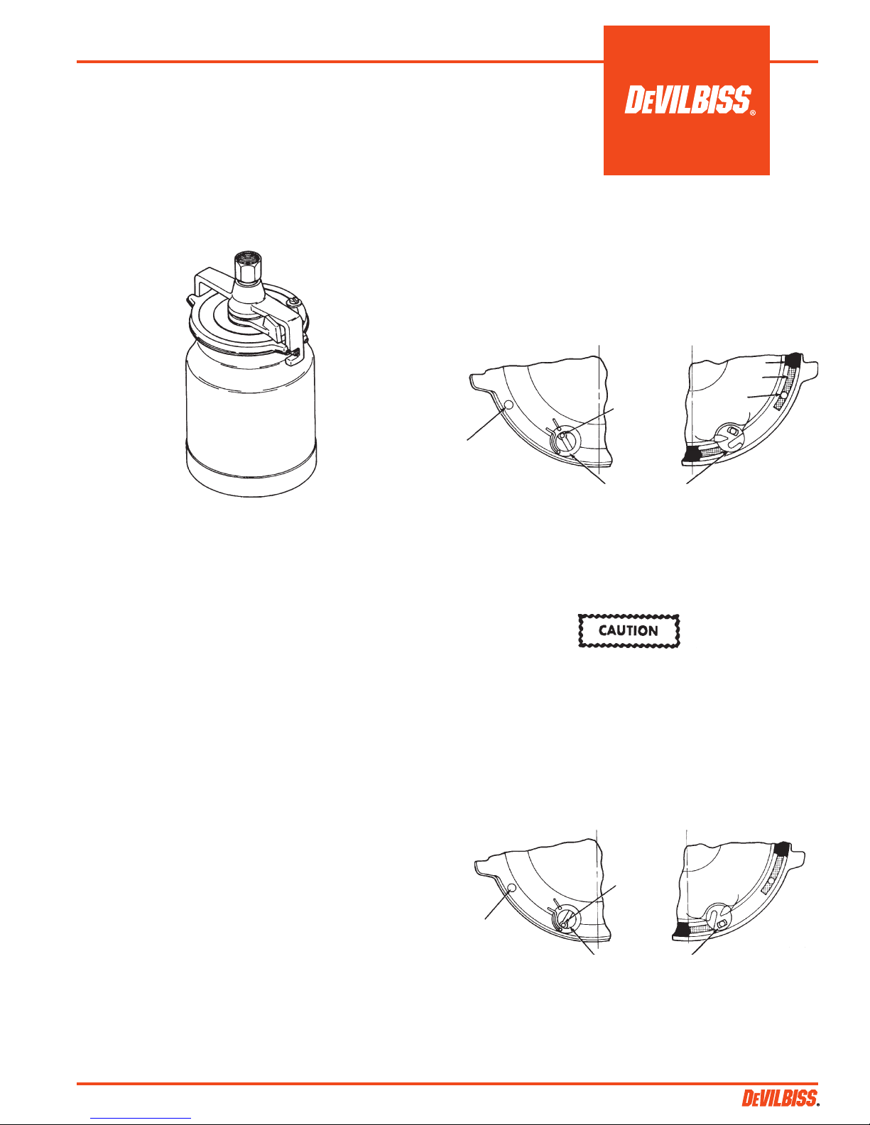
Figure 1
DESCRIPTION
Models: ■ TLC-555 – One quart capacity,
Non-stick coating lined cup
TGC-545 – One quart capacity
OPERATION
Open Vent Mode "O"- To operate in the open vent mode, rotate the
valve with a screwdriver or coin so that the hole in the valve slot is
aligned with the "O" on the lid. See Figure 2.
If the valve slot hole should plug while operating in the "O" vent
mode, use a pointed tool such as a nail or drill bit to probe through
the valve slot hole to clear away the obstruction.
Lid Top Lid Underside
Gasket
Channel
Channel
Vent Hole
Gasket shown
partially removed
Channel
Vent Hole
(Do Not Probe)
D/F
O
Valve slot
hole can be
probed to clean.
Valve in Open Position
Figure 2 – Open Vent Mode
Drip Free Mode "D/F" – To operate in the drip free mode, rotate the
valve with a screwdriver or coin so that the hole in the valve slot is
aligned with the "D/F" on the lid. See Fig. 3
These drip free suction cups have a unique, two position valve which
permits selection of either a drip free spraying mode or a conventional
open vent mode.
In the drip free position, air is directed through the vent in the lid
to a channel beneath the lid gasket before entering the cup at the
valve. This allows the cup to be tilted when full without dripping
paint through the vent. The cup can also be inverted while spraying
without leaking.
The open position isolates the channel and opens a direct vent into
the cup.
The position of the valve is indicated by alignment of the hole in the
valve slot with the marks cast on the lid. These positions are identified
as "O" for vent open and "D/F" for Drip Free.
Note
Non-stick Coating Lined Cup - Only use a wooden or plastic
paddle or mixer for mixing material in the cup (7). A metal
paddle or mixer can scratch the non-stick coating.
Note
For Non-stick Coating Lined Paint Cups, variation in the color
of the non-stick coating is normal. This variation is the result
of the normal production process used with this type of coating. We have selected this particular grade of non-stick coating
because it provides the best overall performance and maximum
durability possible.
Do not probe through the channel vent hole at any time. Do
not probe through the valve slot hole while the valve is in the
"D/F" position. These holes are sealed by a gasket and gasket
damage could result. See Figs. 2 & 3.
Valve Movement – Do not forcibly rotate the valve. If it will not move
freely, soak in solvent or remove the lid assembly from the cup and
press down on the top of the valve until it breaks free. The valve
has free travel vertically of about 1/8". This can be used to push out
the gasket.
Lid Top
Channel
Vent Hole
(Do Not Probe)
D/F
Valve slot
hole sealed (Do Not Probe)
O
Valve in Drip Free
Lid Underside
Gasket shown
partially removed.
Position
Figure 3 - Drip Free Model
Government NSN # 4940-01-208-8876 = TLC-555
SB-4-391-V (6/2016) 1 / 6
Page 2
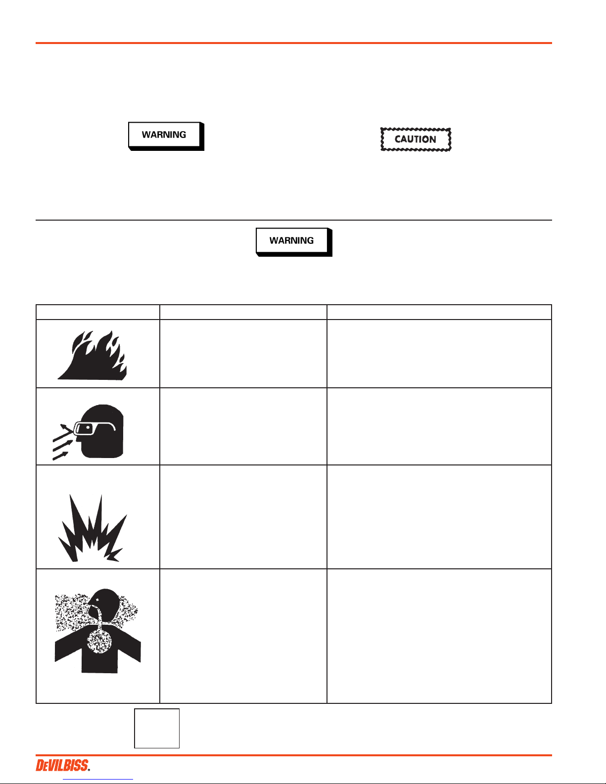
SAFETY PRECAUTIONS
This manual contains important information that ALL users should know and understand BEFORE using the equipment. This information
relates to USER SAFETY and PREVENTING EQUIPMENT PROBLEMS. To help you recognize this information, we use the following terms
to draw your attention to certain equipment labels and portions of this manual. Pay special attention to any label or information that is
highlighted by one of these terms:
Important information to alert you to a situation
that might cause injury or loss of life.
Note
Information that you should pay special attention to.
The following hazards may occur during the normal use of this equipment.
Please read the following chart.
HAZARD SAFEGUARDS
Fire
Solvent Spray
CAUSE
Solvents and coatings can be highly
flammable or combustible, especially
when sprayed.
During cleaning and flushing, solvents
can be forcefully expelled from fluid
and air passages. Some solvents can
cause eye injury or irritation.
Important information that tells how to prevent
damage to equipment
Do not spray near open flames, pilot lights in stoves
or heaters, or other heat sources.
Adequate ventilation must always be provided.
Industrial applications must comply with OSHA
requirements.
Wear eye protection.
Explosion Hazard Incompatible Materials
Inhaling Toxic Substances Certain materials may be harmful if
Chlorinated solvents, such as 1, 1, 1
- Trichloroethane and Methylene Chloride (sometimes called methyl chloride)
can chemically react with the aluminum used in most spray equipment,
and these cups, to produce an explosion hazard. The TLC-555, TGC-545 and
TGC-536 are aluminum.
inhaled, or if there is contact with the
skin.
CA PROP
65
PROP 65 WARNING
WARNING: This product contains chemicals known to the State of California to
cause cancer and birth defects or other reproductive harm.
1. Read the label or data sheet for the material you
intend to spray.
2. Do not use any type of spray coating material
containing these solvents.
3. Do not use these solvents for equipment cleaning
or flushing.
4. If in doubt as to whether a material is compatible,
contact your material supplier.
Follow the requirements of the Safety Data Sheet
supplied by your coating material manufacturer.
Adequate exhaust must be provided to keep the air
free of accumulations of toxic materials.
Use a mask or respirator whenever there is a chance
of inhaling sprayed materials. The mask must be
compatible with the material being sprayed and its
concentration. Equipment must be as prescribed by
an industrial hygienist or safety expert, and be NIOSH
approved.
SB-4-391-V (6/2016)2 / 6
Page 3
INSTALLATION
Cleaning Procedures:
1. Position yoke at right angle to gun body with vent hole in lid
toward rear and lever of cam (3) toward front of gun.
2. Fasten cup lid assembly to gun by attaching nut (2), see Fig. 4,
to fluid inlet nipple on gun. Tighten nut with wrench only until
snug.
3. Strain material to be sprayed through a 60-90 mesh screen before
pouring into cup.
4. Engage pins on cup into yoke and tighten yoke by moving lever
of cam clockwise.
MAINTENANCE
Lid Repair/Replacement:
1. To replace a damaged part, use a 5/16" hex wrench to loosen
and remove adapter (1), nut (2), yoke & cam (3). Lid and tube
assembly are now loose for replacement.
2. Replace damaged parts on the lid and tube assembly. The cam
lever should be located on opposite side of lid from valve (4).
3. Apply sealant (Loctite #262) to the first two full threads of adapter
(1). Insert threaded end of adapter into open end of nut (2).
4. Install adapter (1) and nut (2) in top of lid and tube assembly.
Use a 5/16" hex wrench to tighten firmly (10-12 foot pounds).
Valve and Lid Gasket Replacement:
1. To remove a damaged valve (4) or lid gasket (5), press on top of
valve until it breaks free. The valve pushes the lid gasket from the
seat. The lid gasket may now be removed from the lid. Continue
pressing hard on the valve to remove it from the lid.
2. Install replacement valve (4) through bottom of lid so that the
valve tab is toward center of lid. Snap in place. If necessary, use
a plastic mallet or screwdriver handle to tap the valve in place.
Press the lid gasket firmly in the lid using the end of a crescent
wrench. Insert the side with the black marks first.
CLEANING
Note
Always clean the cam lever (3) surfaces with clean solvent and
a brush. This will keep the cam lever functioning properly. Do
not lubricate the cam.
1. Empty paint from cup and add small amount of clean solvent. The
amount required will vary with different coatings and solvents.
2. Shake cup to wash down inside surfaces. Then spray solvent at
low air pressure (15-20 psi) to flush out fluid passages.
3. Pour out solvent and add same amount of clean solvent.
4a. Again, shake cup. Loosen air cap. Hold a folded cloth over front
of gun and invert cup over solvent receptacle. Trigger with short
bursts to back flush vent channel. With valve in D/F position,
solvent will be expelled with force from the channel vent hole
in lid.
Alternative to Step 4a.
4b. Shut off air to gun. With valve in D/F position, invert cup over
solvent receptable. Trigger gun. Allow solvent to drip out channel vent hole in lid for several seconds, or until clean solvent is
seen.
• Do not probe through the channel vent hole at any time. Do
not probe through the valve slot hole while the valve is in
the D/F position. These holes are sealed by gasket (5) and
gasket damage could occur.
• Do not use abrasives such as a wire brush or steel wool to
clean the inside of the non-stick coating lined cup (7). Damage
to the non-stick surface could result.
IMMERSION
Since all materials in the cup are highly solvent resistant, the cup
assembly may be immersed for cleaning. Immersion should not
exceed 24 hours. The use of paint strippers should be avoided because strippers will affect the aluminum as well as other non-metallic
components. If the lid gasket has become swollen from prolonged
exposure to solvents, it will return to its original size without loss of
properties when allowed to dry.
General: For routine cleaning, it is not necessary to remove the lid
gasket. It is not necessary or desirable to remove the valve for any
cleaning procedure. The valve can be depressed from the outside
to assist in removal of the gasket for gasket replacement or when
cleaning dried paint from the channel. The valve should not be forced
past the shoulder which retains it in the lid except for replacement.
Air Pressure: Always clean with reduced air pressure. An air pressure
no greater than 15 to 20 psi will allow quick and thorough cleaning
of the cup and gun and at the same time will:
1. Minimize the amount of solvent atomized into the air.
2. Prevent possibility of damage to cup from excessive back pressure.
3. Reduce the force with which solvent is expelled from the vent.
SB-4-391-V (6/2016) 3 / 6
Page 4
Parts List
Ind.
Ref. Replacement Parts
No. Part No. Description Req.
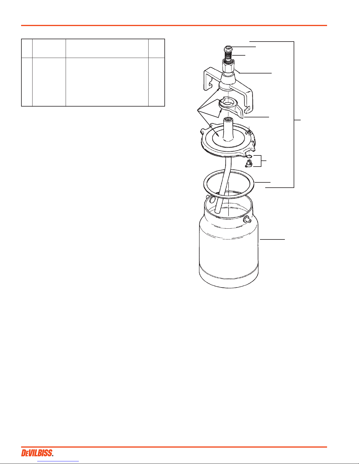
1* Adapter, 1/2" NPS (M) 1
2* Nut, 3/8" NPS (F) 1
3* Cam 1
4* TGC-407-1-K3 Drip Free Valve & Gasket (Kit of 3) 1
5* TGC-9-K5 **Tri Seal® Lid Gasket (Kit of 5) 1
6 TGC-404 Lid Assembly (Quart) 1
7 KR-428-2 Suction Cup Assy. (Quart) 1
TLC-401 Suction Cup Assy. (Non-stick, Quart)
* KK-5007 Repair Kit includes Ref. Nos. 1-5. Repair kit contains enough
parts to repair one complete assembly.
Suffix -K3 designates a kit of multiple parts. Example: TGC-407-1-K3 is a
kit of 3 drip free valves.
** Registered Trademark of Tri-Seal International.
Figure 4
Yoke
Keep
these
surfaces
clean.
1
Apply sealant to
first two threads
(Loctite #262).
2
3
4
5
6
7
SB-4-391-V (6/2016)4 / 6
Page 5

NOTES
SB-4-391-V (6/2016) 5 / 6
Page 6

WARRANTY POLICY
DeVilbiss products are covered by Carlisle Fluid Technologies one year materials and workmanship limited warranty.
The use of any parts or accessories, from a source other than Carlisle Fluid Technologies, will void all warranties.
For specic warranty information please contact the closest Carlisle Fluid Technologies location listed below.
Carlisle Fluid Technologies reserves the right to modify equipment specications without prior notice.
DeVilbiss®, Ransburg®, MS®, BGK®, and Binks® are registered trademarks of
Carlisle Fluid Technologies, Inc. ©2016 Carlisle Fluid Technologies, Inc. All rights reserved.
DeVilbiss is part of Carlisle Fluid Technologies, a global leader in innovative
nishing technologies. For technical assistance or to locate an authorized distributor,
contact one of our international sales and customer support locations.
USA/Canada
info@carlisleft.com
Tel: 1-888-992-4657
Fax: 1-888-246-5732
United Kingdom
info@carlisleft.eu
Tel: +44 (0)1202 571 111
Fax: +44 (0)1202 573 488
China
mkt@carlisleft.com.cn
Tel: +8621-3373 0108
Fax: +8621-3373 0308
For the latest information about our products, visit www.carlisleft.com.
Mexico
ventas@carlisleft.com.mx
Tel: 011 52 55 5321 2300
Fax: 011 52 55 5310 4790
France
info@carlisleft.eu
Tel: +33(0)475 75 27 00
Fax: +33(0)475 75 27 59
Japan
overseas-sales@carlisleft.co.jp
Tel: 081 45 785 6421
Fax: 081 45 785 6517
Brazil
vendas@carlisleft.com.br
Tel: +55 11 5641 2776
Fax: 55 11 5641 1256
Germany
info@carlisleft.eu
Tel: +49 (0) 6074 403 1
Fax: +49 (0) 6074 403 281
Australia
sales@carlisleft.com.au
Tel: +61 (0) 2 8525 7555
Fax: +61 (0) 2 8525 7575
DeVilbiss Automotive Renishing is part of Carlisle Fluid Technologies,
a global leader in innovative nishing technologies. For technical assistance
or to locate an authorized distributor, contact one of our international sales
and customer support locations.
USA/Canada
www.autorenishdevilbiss.com
askus@carlisleft.com
Toll Free Tel: 1-800-445-3988
Toll Free Fax: 1-800-445-6643
Mexico
www.autorenishdevilbiss.com.mx
Toll Free Tel: 1-888-835-6232 USA
SB-4-391-V (6/2016)6 / 6
Page 7

MANUAL DE SERVICIO
Kit de reparación KK-5007
■
TLC-555 Y TGC-545
TAZAS DE SUCCIÓN LIBRES DE GOTEO
Importante: Antes de usar este equipo, lea todas las precauciones de seguridad y las instrucciones. Guárdelo para
futuro uso.
Figura 1
DESCRIPCIÓN
Modelos: ■ TLC-555 – Capacidad de un cuarto de galón,
Taza revestida con revestimiento antiadherente
TGC-545 – Capacidad de un cuarto de galón
Estas tazas de succión libres de goteo tienen una válvula exclusiva con
dos posiciones que permite la selección de un modo de atomización
libre de goteo o un modo convencional con ventilación abierta.
En la posición libre de goteo, el aire es dirigido a través del orificio de
ventilación en la tapa hacia un canal debajo del empaque de la tapa
antes de entrar en la taza por la válvula. Esto permite inclinar la taza
cuando se encuentra llena sin derramar pintura a través del orificio de
ventilación. También se puede invertir la taza al atomizar sin escapes.
La posición abierta aísla el canal y abre un orificio de ventilación
directo hacia la taza.
La posición de la válvula se indica por la alineación del orificio en
la ranura de la válvula con las marcas fundidas en la tapa. Estas
posiciones se identifican como "O" para ventilación abierta y "D/F"
para Libre de goteo.
Nota
Taza con revestimiento antiadherente - Use únicamente una
paleta o un mezclador de madera o de plástico para mezclar
materiales en la taza (7). Una paleta o mezclador de metal
puede rayar el revestimiento de revestimiento antiadherente.
Nota
En las Tazas de Pintura con Revestimiento de Antiadherente,
es normal la variación del color en el revestimiento de
antiadherente. Esta variación es el resultado del proceso
de producción normal con este tipo de recubrimiento.
Hemos seleccionado esta clase particular de revestimiento
antiadherente porque proporciona el mejor desempeñ o global
y la máxima durabilidad posible.
OPERACIÓN
Modo con orificio de ventilación abierto "O"- Para funcionar en el modo
con orificio de ventilación abierto, gire la válvula con un desarmador
o con una moneda de manera que el orificio en la ranura de la válvula
quede alineado con el "O" en la tapa. Ver Figura 2.
Si se obstruye el orificio en la ranura de la válvula mientras se
funciona en el modo con orificio de ventilación abierto "O", use una
herramienta puntiaguda como un clavo o una broca de barrena para
penetrar a través del orificio en la ranura de la válvula para despejar
la obstrucción.
Parte superior de la tapa Parte inferior de la tapa
Empaque
Canal
Orificio de
ventilación
del canal
El empaque
se muestra parcialmente quitado
Orificio de ventilación
del canal
(No introduzca
nada)
D/F
O
Se puede penetrar el orificio
en la ranura de
la válvula para
limpiar.
Válvula en posición
Abierta
Figura 2 – Modo con orificio de ventilación abierto
Modo libre de goteo "D/F" – Para funcionar en el modo libre de goteo,
gire la válvula con un desarmador o con una moneda de manera que
el orificio en la ranura de la válvula quede alineado con el "D/F" en
la tapa. Ver Fig. 3
PRECAUCIÓN
Nunca introduzca nada a través del orificio de ventilación del
canal. No introduzca nada a través del orificio en la ranura
de la válvula mientras la válvula se encuentre en la posición
"D/F". Estos orificios son sellados por un empaque y el empaque
puede dañarse. Ver las figuras 2 y 3.
Movimiento de la válvula – No gire la válvula forzándola. Si no se
desplaza con libertad, vierta disolvente o quite la unidad de la tapa de
la taza y presione la parte superior de la válvula hasta que se desplace.
La válvula tiene un desplazamiento libre vertical de aproximadamente
1/8”. Esto se puede utilizar para sacar el empaque.
Parte superior de la tapa
O
D/F
Orificio de ventilación
del canal
(No introduzca
nada)
Orificio en la
ranura de la
válvula sellado (No introduzca
nada)
Válvula en posición
Libre de goteo
Parte inferior de la tapa
El empaque
se muestra parcialmente quitado
Figura 3 - Modelo libre de goteo
Gobierno NSN # 4940-01-208-8876 = TLC-555
SB-4-391-V (6/2016) ES-1 / 5
Page 8

PRECAUCIONES DE SEGURIDAD
Este manual contiene información importante que TODOS los usuarios deben conocer y comprender ANTES de utilizar el equipo. Esta
información se relaciona con la SEGURIDAD DEL USUARIO y CÓMO EVITAR PROBLEMAS CON LOS EQUIPOS. Para ayudarle a reconocer
esta información, utilizamos los siguientes términos para llamar su atención a ciertas etiquetas de los equipos y partes de este manual.
Preste atención especial a cualquier etiqueta o información que se destaque con uno de estos términos:
ADVERTENCIA
Información importante para alertarlo acerca
de una situación que pueda ocasionar lesión o
pérdida de la vida.
Nota
Información a la que debe prestar atención especial.
ADVERTENCIA
Durante el uso normal de este equipo pueden ocurrir las siguientes situaciones de peligro.
Sírvase leer la siguiente tabla.
PELIGRO MEDIDAS PREVENTIVAS
Incendio
Atomizar solventes
CAUSA
Los solventes y recubrimientos
pueden ser altamente inflamables o
combustibles, especialmente cuando
se atomizan.
Durante la limpieza y purga, los
solventes pueden expulsarse con
fuerza de los pasajes de fluido y aire.
Algunos solventes pueden causar
lesiones o irritación en los ojos.
Información importante que indica cómo prevenir
daño al equipo
No atomice cerca de llamas descubiertas, luces piloto
en cocinas o calentadores u otras fuentes de calor.
Siempre debe haber ventilación adecuada. Las
aplicaciones industriales deben cumplir con los
requisitos de OSHA.
Use gafas de protección.
PRECAUCIÓN
Peligro de explosión –
Materiales incompatibles
Inhalación de sustancias tóxicas Ciertos materiales pueden ser dañi-
Los solventes clorados, tales como 1, 1,
1 – Tricloroetano y cloruro de metileno
(denominado algunas veces cloruro
de metilo) pueden generar reacciones
químicas con el aluminio utilizado en la
mayoría de los equipos pulverizadores
y estas tazas, ocasionando peligro
de explosión. TLC-555, TGC-545 y
TGC-536 son aluminio.
nos si se inhalan o si tienen contacto
con la piel.
PROP
65
DE CA
ADVERTENCIA PROP 65
ADVERTENCIA: Este producto contiene sustancias químicas que según información
en poder del estado de California producen cáncer, defectos de nacimiento y otros
daños al sistema reproductor.
1. Lea la etiqueta u hoja de seguridad para el material que piensa atomizar.
2. No use ningún tipo de material de recubrimiento
atomizado que contenga estos solventes.
3. No use estos solventes para limpieza o purga del
equipo.
4. Si tiene dudas acerca de si un material es compatible, póngase en contacto con su proveedor de
materiales.
Siga los requisitos de la Hoja de datos de seguridad
(SDS) suministrada por el fabricante del material de
recubrimiento.
Debe proveerse de un escape adecuado para mantener el aire libre de acumulaciones de vapores tóxicos.
Use una máscara o respirador siempre que haya
riesgo de inhalar materiales atomizados. La máscara
debe ser compatible con el material que se atomiza
y su concentración. El equipo debe ser como el recomendado por un higienista industrial o experto en
seguridad y aprobado por NIOSH.
SB-4-391-V (6/2016)ES-2 / 5
Page 9

INSTALACIÓN
Procedimientos de limpieza:
1. Coloque la varilla de unión en ángulo recto respecto del cuerpo
de la pistola con el orificio de ventilación en la tapa orientado
hacia la parte trasera y la palanca de la leva (3) hacia la parte
delantera de la pistola.
2. Sujete la unidad de la tapa de la taza a la pistola fijando la tuerca
(2), ver Fig. 4, a la boquilla de entrada de fluido en la pistola.
Apriete la tuerca con la llave únicamente hasta dejarla bien
ajustada.
3. Filtre el material que va a ser atomizado a través de un tamiz de
malla 60-90 antes de verterlo en la taza.
4. Enganche las clavijas de la taza en la varilla de unión y apriete
la varilla de unión moviendo la palanca de la leva en sentido
horario.
MANTENIMIENTO
Reparación/Reemplazo de la tapa:
1. Para reemplazar una pieza dañada, use una llave hexagonal de
5/16" para aflojar y quitar el adaptador (1), la tuerca (2), la varilla
de unión y la leva (3). La unidad de la tapa y el tubo está ahora
floja para reemplazarse.
2. Reemplace las piezas dañadas en la unidad de la tapa y el tubo.
La palanca de la leva debe estar ubicada en el lado opuesto de
la tapa desde la válvula (4).
3. Aplique sellador (Loctite #262) a las primeras dos roscas completas
del adaptador (1). Inserte el extreme roscado del adaptador en
el extremo abierto de la tuerca (2).
4. Instale el adaptador (1) y la tuerca (2) en la parte superior de la
unidad de la tapa y el tubo. Use una llave hexagonal de 5/16"
para apretar con firmeza (10-12 libras pies).
Reemplazo de la válvula y el empaque de la tapa:
1. Para quitar una válvula (4) o el empaque de la tapa (5) dañados,
presione la parte superior de la válvula hasta que se suelte. La
válvula empuja el empaque de la tapa de su encaje. El empaque de
la tapa se puede separar ahora de la tapa. Continúe presionando
con firmeza la válvula para separarla de la tapa.
2. Instale la válvula de reemplazo (4) a través de la parte inferior de
la tapa de manera que la lengüeta de la válvula quede hacia el
centro de la tapa. Encájela en su lugar. Si fuese necesario, use el
mango de un martillo plástico o desarmador para dar golpes a
la válvula hasta que quede en su lugar. Presione con firmeza el
empaque en la tapa utilizando el extremo de una llave ajustable.
Inserte primero el lado con las marcas negras.
1. Vacíe la pintura de la taza y agregue una cantidad pequeña de
solvente limpio. La cantidad necesaria varía según los diferentes
recubrimientos y solventes.
2. Agite la taza para limpiar las superficies interiores. Luego atomice
el solvente con una presión del aire baja (15-20 psi) para purgar
los pasajes de fluido.
3. Vierta el solvente y agregue la misma cantidad de solvente limpio.
4a. Vuelva a agitar la taza. Afloje el casquillo de aire. Sostenga un
paño doblado sobre la parte delantera de la pistola e invierta
la taza sobre el receptáculo del solvente. Accione con ráfagas
pequeñas para retropurgar el canal de ventilación. Con la válvula
en la posición D/F, el solvente será expulsado con fuerza del
orificio de ventilación del canal en la tapa.
Alternativa al Paso 4a.
4b. Interrumpa la entrada de aire en la pistola. Con la válvula en la
posición D/F, invierta la taza sobre el receptáculo del solvente.
Accione la pistola. Deje que el solvente se escurra por el orificio
de ventilación del canal en la tapa por unos segundos o hasta
que se vea el solvente limpio.
PRECAUCIÓN
• No introduzca nada a través el orificio de ventilación del canal
en ningún momento. No introduzca nada a través del orificio
en la ranura de la válvula mientras la válvula se encuentra en
la posición D/F. Estos orificios está sellados por un empaque
(5) y éste podría dañarse.
• No use abrasivos como un cepillo de alambre o virutas finas
de acero para limpiar el interior de la taza con revestimiento
antiadherente (7). Esto puede dañar la superficie de
revestimiento antiadherente.
INMERSIÓN
Debido a que todos los materiales en la taza son altamente resistentes
a los solventes, la unidad de la taza puede sumergirse para su limpieza.
La inmersión no puede sobrepasar las 24 horas. Se debe evitar el uso
de quitapinturas debido a que afectan el aluminio así como otros
componentes no metálicos. Si el empaque de la tapa se expande
debido a la prolongada exposición a los solventes, recuperará su
tamaño original sin pérdida de sus propiedades cuando se deja secar.
LIMPIEZA
Limpie siempre las superficies de la palanca de la leva (3)
con solvente limpio y un cepillo. Esto mantendrá la palanca
funcionando debidamente. No lubrique la leva.
General: Para limpieza de rutina, no es necesario quitar el empaque
de la tapa. No es necesario ni deseable quitar la válvula para cualquier
procedimiento de limpieza. Se puede oprimir la válvula desde fuera
como ayuda para quitar el empaque para reemplazarlo o cuando se
limpia pintura seca del canal. No se debe forzar la válvula más allá del
soporte saliente que la retiene en la tapa excepto para su reemplazo.
Presión del aire: Limpie siempre con presión del aire reducida. Una
presión del aire no superior a entre 15 y 20 psi permitirá la limpieza
rápida y completa de la taza y la pistola y al mismo tiempo:
1. Minimizará la cantidad de solvente atomizado en el aire.
2. Prevendrá la posibilidad de daño a la taza debido al exceso de
contrapresión.
3. Reducirá la fuerza con la cual el solvente es expulsado del orificio
de ventilación.
Nota
SB-4-391-V (6/2016) ES-3 / 5
Page 10

Lista de piezas
No.
de No. de
Ref. repuestos Descripción
Núm. de
piezas
requeridas
1* Adaptador, 1/2" NPS (M) 1
2* Tuerca, 3/8" NPS (F) 1
3* Leva 1
4* TGC-407-1-K3 Válvula libre de goteo y empaque
(Kit de 3) 1
5* TGC-9-K5 **Empaque de la tapa**Tri Seal®
(Kit de 5) 1
6 TGC-404 Unidad de la tapa (cuarto de galón) 1
7 KR-428-2 Unidad de la taza de succión.
(Cuarto de galón) 1
TLC-401 Unidad de la taza de succión.
(Revestimiento antiadherente, cuarto de galón)
* El Kit de reparación * KK-5007 incluye Núm. de Ref. 1-5. El kit de repara-
ción contiene suficientes piezas para reparar una unidad completa.
El sufijo -K3 designa un kit de piezas múltiples. Ejemplo: TGC-407-1-K3 es
un kit de 3 válvulas libres de goteo.
** Marca registrada de Tri-Seal International.
Figura 4
Varilla de
unión
Mantenga
estas
superficies
limpias.
1
Aplique sellador a las
dos primeras roscas
(Loctite #262).
2
3
4
5
6
7
SB-4-391-V (6/2016)ES-4 / 5
Page 11

POLÍTICA DE GARANTÍAS
Los productos DeVilbiss están cubiertos por la garantía limitada de materiales y mano de obra por un año
de Carlisle Fluid Technologies. El uso de cualquier pieza o accesorio de una fuente que no sea Carlisle Fluid
Technologies, anulará todas las garantías. Para obtener información especíca sobre la garantía, favor ponerse
en contacto con el local de Carlisle Fluid Technologies más cercano a usted entre los listados a continuación.
Carlisle Fluid Technologies se reserva el derecho de modicar las especicaciones del equipo sin previo aviso.
DeVilbiss®, Ransburg®, MS®, BGK®, y Binks® son marcas registradas de Carlisle Fluid Technologies, Inc.
©2016 Carlisle Fluid Technologies, Inc. Reservados todos los derechos.
DeVilbiss es parte de Carlisle Fluid Technologies, un líder global en tecnologías de
acabados innovadores. Para asistencia técnica o para localizar un distribuidor autorizado,
póngase en contacto con uno de nuestros centros internacionales de ventas y apoyo al
cliente listados.
EE.UU/Canadá
info@carlisleft.com
Teléfono: 1-888-992-4657
Fax: 1-888-246-5732
Reino Unido
info@carlisleft.eu
Teléfono: +44 (0)1202 571 111
Fax: +44 (0)1202 573 488
China
mkt@carlisleft.com.cn
Teléfono: +8621-3373 0108
Fax: +8621-3373 0308
Para obtener la última información sobre nuestros productos, visite www.carlisleft.com.
DeVilbiss Automotive Renishing es parte de Carlisle Fluid Technologies, un líder
global en tecnologías de acabados innovadores. Para asistencia técnica o para
localizar un distribuidor autorizado, póngase en contacto con uno de nuestros
centros internacionales de ventas y apoyo al cliente listados.
México
ventas@carlisleft.com.mx
Teléfono: 011 52 55 5321 2300
Fax: 011 52 55 5310 4790
Francia
info@carlisleft.eu
Teléfono: +33(0)475 75 27 00
Fax: +33(0)475 75 27 59
Japón
overseas-sales@carlisleft.co.jp
Teléfono: 081 45 785 6421
Fax: 081 45 785 6517
Brasil
vendas@carlisleft.com.br
Teléfono: +55 11 5641 2776
Fax: 55 11 5641 1256
Alemania
info@carlisleft.eu
Teléfono: +49 (0) 6074 403 1
Fax: +49 (0) 6074 403 281
Australia
sales@carlisleft.com.au
Teléfono: +61 (0) 2 8525 7555
Fax: +61 (0) 2 8525 7575
EE.UU/Canadá
www.autorenishdevilbiss.com
askus@carlisleft.com
Tel gratuito: 1-800-445-3988
Fax gratuito: 1-800-445-6643
SB-4-391-V (6/2016) ES-5 / 5
México
www.autorenishdevilbiss.com.mx
Tel gratuito: 1-888-835-6232 USA
Page 12

MANUEL DE SERVICE
Trousse de réparation KK-5007
■
TLC-555 ET TGC-545
RÉSERVOIRS À SUCCION À L’ÉPREUVE DES FUITES
Important : Prendre connaissance de toutes les consignes de
sécurité et des directives avant d’utiliser ce matériel. Conserver
pour utilisation future.
Figure 1
DESCRIPTION
Modèles : ■ TLC-555 : capacité de 950 ml (1 pinte)
Réservoir à doublure de revêtement anti-adhésif
TGC-545 : capacité de 946 ml (1 pinte)
Ces réservoirs à l’épreuve des fuites sont munis d’une soupape unique,
à deux positions, qui permet de choisir un mode de pulvérisation sans
fuite ou un mode conventionnel à évent ouvert.
Dans la position sans fuite, l’air est dirigé à travers l’évent du couvercle
vers un sillon sous l’anneau d’étanchéité du couvercle avant de
pénétrer dans le réservoir, au niveau de la soupape. Cela permet
de pencher le réservoir lorsqu’il est plein sans que la peinture ne
dégoutte à travers l’évent. Le réservoir peut également ètre renversé
en pulvérisant, sans fuir.
La position ouverte isole le sillon et ouvre un évent direct vers le
réservoir.
La position de la soupape est indiquée en alignant l’orifice de la fente
de la soupape avec les marques qui se trouvent sur le couvercle. Ces
positions sont identifiées par « O » pour l’évent ouvert et par « D/F
» pour le mode sans fuite.
Remarque
Réservoir en revêtement anti-adhésif : Utiliser uniquement une
spatule ou un mélangeur en bois ou en plastique pour remuer
le produit dans le réservoir en revêtement anti-adhésif (7).
L’utilisation d’une spatule ou d’un mélangeur en métal peut
égratigner le revètement de revêtement anti-adhésif.
Remarque
La couleur du revètement en revêtement anti-adhésif peut
varier dans les différents réservoirs recouverts de revêtement
anti-adhésif. Ces différences sont la conséquence du processus
normal de production utilisé pour ce type de revètement. Nous
avons choisi cette qualité de revètement de revêtement antiadhésif, car elle fournit le meilleur rendement général et la plus
grande durabilité possible.
FONCTIONNEMENT
Mode à évent ouvert « O » : Pour travailler en mode à évent ouvert,
faire pivoter la soupape à l’aide d’un tournevis ou d’une pièce de
monnaie de manière à ce que l’orifice de la fente de la soupape soit
aligné avec le « O » qui se trouve sur le couvercle. Voir figure 2.
Si l’orifice de la fente de la soupape se bouche lors du fonctionnement
en mode d’évent ouvert, utiliser un outil pointu comme un clou ou un
foret pour pénétrer dans l’orifice de la fente de la soupape et déloger
ce qui l’obstrue.
Dessus du couvercle Dessous du couvercle
Anneau
d’étanchéité
Sillon
Trou
d’évent
du sillon
Anneau d’étanchéité
montré partiellement
retiré
Trou d’évent
du sillon :
(ne pas y insérer
d’objet.)
D/F
O
On peut insérer
un objet dans
l’orifice de la
fente de la soupape pour
le dégager.
Soupape en
position ouverte
Figure 2 : mode à évent ouvert
Mode sans fuite « D/F » : Pour travailler en mode sans fuite, faire
pivoter la soupape à l’aide d’un tournevis ou d’une pièce de monnaie
de manière à ce que l’orifice de la fente de la soupape soit aligné avec
le « D/F » qui se trouve sur le couvercle. Voir figure 3.
AVERTISSEMENT
Ne jamais insérer d’objet dans le trou d’évent du sillon. Ne pas
insérer d’objet dans l’orifice de la fente de la soupape alors
que la soupape est en position « D/F ». Ces ouvertures sont
scellées par un anneau d’étanchéité et l’insertion d’un objet
risque de l’endommager. Voir figures 2 et 3.
Mouvement de la soupape : Ne pas tourner la soupape de force. Si
elle ne tourne pas librement, faire tremper dans du solvant ou retirer
le module du couvercle du réservoir et appuyer sur le sommet de la
soupape jusqu’à ce qu’elle soit libérée. La soupape peut bouger librement d’environ 3 mm (1/8 po) à la verticale. Cela permet de pousser
l’anneau d’étanchéité pour le dégager.
Dessus du couvercle
Orifice de la
fente de la
soupape :
(ne pas y insérer
d’objet.)
Soupape en posi-
D/F
Trou d’évent
du sillon :
(ne pas y insérer
d’objet.)
O
tion sans fuite
Figure 3 : modèle sans fuite
DSN gouvernemental n° 4940-01-208-8876 = TLC-555
Dessous du couvercle
Anneau d’étanchéité
montré partiellement
retiré
SB-4-391-V (6/2016)FR-1 / 5
Page 13

CONSIGNES DE SÉCURITÉ
Ce manuel renferme des renseignements importants que TOUS les utilisateurs doivent connaître et comprendre AVANT d’utiliser ce matériel.
Cette information se rapporte à la SÉCURITÉ DE L’UTILISATEUR et à la PRÉVENTION DES PROBLÈMES DE FONCTIONNEMENT DU MATÉRIEL.
Pour aider les utilisateurs à se retrouver dans cette information, nous avons recours aux termes suivants pour attirer l’attention sur certaines
étiquettes du matériel et des sections du manuel. Porter une attention particulière à toute étiquette ou information qui est soulignée par
l’un de ces termes :
MISE EN GARDE
Information importante pour attirer l’attention
sur une situation pouvant occasionner des blessures graves ou même la mort.
Information à laquelle il faut porter une attention particulière.
Information importante servant à prévenir les
dommages au matériel
Remarque
AVERTISSEMENT
MISE EN GARDE
Les dangers suivants peuvent se produire durant l’usage normal de cet appareil.
Lire attentivement le tableau suivant.
DANGER MESURES DE PROTECTION
Feu
Pulvérisation de solvants
CAUSE
Les solvants et les revètements
peuvent ètre hautement inflammables
ou combustibles, surtout lorsqu’ils sont
vaporisés.
Durant le nettoyage et le rinçage du
matériel, des solvants peuvent ètre
évacués sous pression des conduites
d’air et de liquide. Certains solvants
peuvent occasionner des blessures ou
de l’irritation aux yeux.
Ne pas vaporiser près de flammes, veilleuses des
cuisinières et appareils de chauffage, ou autres
sources de chaleur.
Il est essentiel de toujours fournir une ventilation
adéquate. Toutes les utilisations industrielles doivent
respecter les normes de l’OSHA.
Porter des lunettes de protection.
Risque d’explosion :
matériaux incompatibles
Inhalation de substances toxiques
Les solvants chlorés, par exemple :
le trichloroéthane 1-1-1 et le
dichlorométhane (parfois appelés
chlorométhane), peuvent causer une
réaction chimique avec l’aluminium
contenu dans la plupart des pistolets
pulvérisateurs, et leurs réservoirs, et
provoquer un risque d’explosion. Les
modèles TLC-555, TGC-545 et TGC-536
sont faits d’aluminium.
Certains produits peuvent ètre nocifs
lorsqu’inhalés, ou s’ils entrent en
contact avec la peau.
CA PROP
65
PROPOSITION 65 AVERTISSEMENT
AVERTISSEMENT: Ce produit contient des produits chimiques connus de l’état de
Californie pour causer des malformations congénitales ou d’autres cancers et
troubles de la reproduction.
1. Lire l’étiquette ou la fiche technique du produit à
pulvériser.
2. N’utiliser aucun type de matériaux de revètement
contenant ces solvants.
3. Ne pas utiliser ces solvants pour nettoyer et rincer
le matériel.
4. En cas de doute à savoir si un produit est
compatible avec le matériel, communiquer avec le
fournisseur du matériel.
Suivre les recommandations de sécurité de la fiche
technique fournie par le fabricant du produit de
revètement à pulvériser.
Un système d’évacuation adéquat doit ètre prévu afin
d’éviter l’accumulation de vapeurs toxiques.
Utiliser un masque ou un respirateur lorsqu’il existe
un risque d’inhaler les produits pulvérisés. Le
masque doit ètre compatible avec le produit utilisé et
sa concentration. Le matériel de protection doit ètre
recommandé par un expert en santé et sécurité au
travail et approuvé par NIOSH.
SB-4-391-V (6/2016) FR-2 / 5
Page 14

INSTALLATION
Méthodes de nettoyage :
1. Placer l’étrier à angle droit par rapport au corps du pistolet, avec
le trou d'évent du couvercle vers l’arrière et le levier de came (3)
vers l’avant du pistolet.
2. Installer le module du couvercle du réservoir au pistolet en
fixant l’écrou (voir l’élément nº 2 de la figure 4), au mamelon
d’admission du liquide sur le pistolet. Resserrer l’écrou avec une
clé, sans forcer.
3. Filtrer le produit à pulvériser à travers un tamis 60 ou 90 avant
de le verser dans le réservoir.
4. Engager les goupilles du réservoir dans l’étrier et resserrer en
déplaçant le levier de came dans le sens des aiguilles d’une
montre.
ENTRETIEN
Réparation/remplacement du couvercle :
1. Pour remplacer toute pièce endommagée, utiliser une clé
hexagonale 5/16 po pour desserrer et retirer l’adaptateur (1),
l’écrou (2), l’étrier et la came (3). Les pièces du module couvercle
et du tube sont maintenant libres et peuvent ètre remplacés.
2. Remplacer les pièces endommagées du module du couvercle et
du tube. Le levier de came doit ètre situé du côté du couvercle
opposé à la soupape (4).
3. Appliquer un agent d'étanchement (Loctite nº 262) aux deux
premiers filets de l’adaptateur (1). Insérer l’extrémité filetée de
l’adaptateur dans l’extrémité ouverte de l’écrou (2).
4. Installer l’adaptateur (1) et l’écrou (2) au sommet du module du
couvercle et du tube. Utiliser une clé hexagonale 5/16 po pour
bien resserrer l’écrou (15 à 18 kg/m [10-12 pi/lb]).
Remplacement de la soupape et de l’anneau d’étanchéité du
couvercle :
1. Pour retirer une soupape (4) ou un couvercle de soupape (5)
endommagé, appuyer sur le sommet de la soupape jusqu’à ce
qu’elle soit libérée. La soupape pousse l’anneau d’étanchéité
du couvercle hors de son assise. Il est maintenant possible de
retirer l’anneau du couvercle. Continuer à appuyer fermement
sur la soupape pour la libérer du couvercle.
2. Installer la soupape de rechange (4) à travers le bas du couvercle
de manière à ce que la languette de la soupape soit dirigée
vers le centre du couvercle. Enclencher en place. Si nécessaire,
utiliser un maillet de plastique ou la poignée d’un tournevis pour
enfoncer la soupape en place. Appuyer fermement sur l’anneau
d’étanchéité du couvercle pour le faire pénétrer en place à l’aide
de l’extrémité d’une clé à molette. Insérer d’abord le côté portant
les marques noires.
1. Vider la peinture du réservoir et verser une petite quantité de
solvant propre à l’intérieur. La quantité nécessaire variera en
fonction du type de revètement et de solvant.
2. Agiter le réservoir afin de bien laver les surfaces intérieures.
Vaporiser ensuite le solvant avec une pression d’air réduite 103
à 134 kPa (15 à 20 psi) pour expulser le liquide des conduits.
3. Jeter le solvant et remplacer par une quantité égale de solvant
propre.
4a. Agiter de nouveau le réservoir. Desserrer l’anneau déflecteur.
Tenir un linge plié devant le pistolet et retourner le réservoir sur
le contenant de solvant. Appuyer à petits coups sur la gâchette
pour que solvant circule à l’envers dans le conduit de l’évent.
En mettant la soupape en position D/F, le solvant sera expulsé
avec force du trou d’évent du sillon dans le couvercle.
Solution de rechange à l’étape 4a.
4b. Couper l'alimentation en air du pistolet. En mettant la soupape
en position D/F position, retourner le réservoir sur le réservoir
de solvant. Appuyer sur la gâchette. Laisser le solvant dégoutter
du trou d’évent du sillon dans le couvercle pendant plusieurs
secondes, ou jusqu’à ce que du solvant propre s’écoule.
AVERTISSEMENT
• Ne jamais insérer d’objet dans le trou d’évent du sillon. Ne
pas insérer d’objet dans l’orifice de la fente de la soupape
alors que la soupape est en position D/F. Ces ouvertures sont
scellées par un anneau d’étanchéité (5) et l’insertion d’un
objet risque de l’endommager.
• Ne pas utiliser d’abrasif comme une brosse métallique ou
de la laine d’acier pour nettoyer l’intérieur du réservoir en
revêtement anti-adhésif (7). La surface de revêtement antiadhésif pourrait être endommagée.
IMMERSION
Étant donné que tous les matériaux composant le réservoir sont très
résistants aux solvants, le module du réservoir peut ètre immergé pour
le nettoyage. L’immersion de doit pas dépasser 24 heures. L’utilisation
de décapant à peinture est à éviter, car ces produits peuvent réagir
avec aluminium ainsi qu’avec d’autres composants non métalliques.
Si l’anneau d’étanchéité du couvercle gonfle suite à une exposition
prolongée aux solvants, il reprendra sa taille originale sans perdre
ses propretés une fois asséché.
NETTOYAGE
Remarque
Toujours nettoyer les surfaces du levier de came (3) avec
du solvant propre et une brosse. Cela assurera son bon
fonctionnement. Ne pas lubrifier la came.
Général : Pour un nettoyage de routine, il n’est pas nécessaire de
retirer l’anneau d’étanchéité du réservoir. Il n’est pas nécessaire ni
souhaitable de retirer la soupape pour effectuer le nettoyage. Il est
possible d’abaisser la soupape de l’extérieur afin de contribuer au retrait
de l’anneau d’étanchéité, pour le remplacer, ou déloger la peinture
séchée du sillon. La soupape ne doit pas ètre poussée plus loin que
l’épaulement qui la retient dans le couvercle, sauf pour la remplacer.
Pression d’air : Toujours réduire la pression d’air pour effectuer le
nettoyage. Une pression d’air ne dépassant pas 103 à 134 kPa (15 à
20 psi) permettra un nettoyage rapide et profond du réservoir et du
pistolet tout en assurant de :
1. réduire la quantité de solvant pulvérisé dans l’air;
2. prévenir les risques que la contre-pression excessive
n’endommage le réservoir;
3. réduire la force avec laquelle le solvant est expulsé de l’évent.
SB-4-391-V (6/2016)FR-3 / 5
Page 15

Liste des pièces
N°
de N° de pièce
réf. détachée Description
Nb de
pièces
nécessaire
1* Adaptateur, 1/2 po NPS (M) 1
2* Écrou, 3/8 NPS (F) 1
3* Came 1
4* TGC-407-1-K3 Soupape et anneau d’étanchéité sans
fuite (ensemble de 3) 1
5* TGC-9-K5 **Anneau d’étanchéité de couvercle
Tri Seal® (ensemble de 5) 1
6 TGC-404 Module du couvercle (946 ml
[1 pinte]) 1
7 KR-428-2 Module de réservoir à succion
(946 ml [1 pinte]) 1
TLC-401 Module de réservoir à succion
(Revêtement anti-adhésif, 946 ml [1 pinte])
* La trousse de réparation KK-5007 contient les numéros de réf. 1 à 5. La
trousse de réparation contient suffisamment de pièces pour réparer un
module complet.
Le suffixe K3 désigne un ensemble comprenant plusieurs pièces. Par
exemple : L’ensemble TGC-407-1-K3 comprend 3 soupapes sans fuite.
** Marque de commerce enregistrée de Tri-Seal International.
Figure 4
Garder
ces
surfaces
propres.
Étrier
1
Appliquer un agent
d'étanchement (Loctite n° 262) aux deux
premiers filets.
2
3
4
5
6
7
SB-4-391-V (6/2016) FR-4 / 5
Page 16

CONDITIONS DE GARANTIE
Les produits DeVilbiss sont couverts contre les vices de matériel et de fabrication par une garantie limitée d’un
an de Carlisle Fluid Technologies. L’utilisation de toutes pièces ou accessoires issus d’une source autre que
Carlisle Fluid Technologies, annulera toutes les garanties. Pour des informations précises sur la garantie, veuillez
contacter le site de Carlisle Fluid Technologies le plus proche, que vous trouverez sur la liste ci-dessous.
Carlisle Fluid Technologies se reserve le droit de modier sans préavis les spécications de l’équipement.
DeVilbiss®, Ransburg®, MS®, BGK®, et Binks® sont des marques de commerce déposées de
Carlisle Fluid Technologies, Inc. ©2016 Carlisle Fluid Technologies, Inc. Tous droits réservés.
DeVilbiss fait partie de Carlisle Fluid Technologies, un leader mondial dans le domaine des
technologies innovatrices de nition. Pour toute assistance technique ou pour localiser un
distributeur agréé, veuillez contacter l’un de nos bureaux de ventes internationaux et de
soutien client.
USA/Canada
info@carlisleft.com
Tél: 1-888-992-4657
Fax: 1-888-246-5732
Royaume-Uni
info@carlisleft.eu
Tél: +44 (0)1202 571 111
Fax: +44 (0)1202 573 488
Chine
mkt@carlisleft.com.cn
Tél: +8621-3373 0108
Fax: +8621-3373 0308
Pour obtenir les dernières informations sur nos produits, visitez www.carlisleft.com.
Mexique
ventas@carlisleft.com.mx
Tél: 011 52 55 5321 2300
Fax: 011 52 55 5310 4790
France
info@carlisleft.eu
Tél: +33(0)475 75 27 00
Fax: +33(0)475 75 27 59
Japon
overseas-sales@carlisleft.co.jp
Tél: 081 45 785 6421
Fax: 081 45 785 6517
Brésil
vendas@carlisleft.com.br
Tél: +55 11 5641 2776
Fax: 55 11 5641 1256
Allemagne
info@carlisleft.eu
Tél: +49 (0) 6074 403 1
Fax: +49 (0) 6074 403 281
Australie
sales@carlisleft.com.au
Tél: +61 (0) 2 8525 7555
Fax: +61 (0) 2 8525 7575
DeVilbiss Automotive Renishing fait partie de Carlisle Fluid Technologies, un leader
mondial dans le domaine des technologies innovatrices de nition. Pour toute
assistance technique ou pour localiser un distributeur agréé, veuillez contacter l’un
de nos bureaux de ventes internationaux et de soutien client.
USA/Canada
www.autorenishdevilbiss.com
askus@carlisleft.com
Tél sans frais: 1-800-445-3988
Fax sans frais: 1-800-445-6643
Mexique
www.autorenishdevilbiss.com.mx
Tél sans frais: 1-888-835-6232 USA
SB-4-391-V (6/2016)FR-5 / 5
 Loading...