

Page 1

TB-1022
Replaces TB-1022
Technical Bulletin
Professional Pressure
Feed Spraygun
Gun Repair Kit
PRO-470
ghcustserv@carlisleft.com
800.992.4657
www.devilbiss.com
Page 2

TB-1022
Table of Contents
Topic Page
EC Declaration of Conformity .................................................................................................................................3
Operational Description ............................................................................................................................................3
Construction Features, Materials of Construction, ....................................................................................4
Specications & Technical Data
Safety Precautions .......................................................................................................................................................5
Installation, Operation, Preventive Maintenance & Cleaning, .............................................................6
Spray Gun Lubrication
Parts Replacement/Maintenance ..............................................................................................................7–12
A. Servicing Air Valve ..............................................................................................................................7–8
B. Needle Packing, Spreader Valve Assembly, Fluid Inlet Seal ............................................. 9
C. Spray Head Seal Replacement ....................................................................................................... 10
D. Chart 1 – Air Caps ................................................................................................................................. 11
Chart 2 – Fluid Nozzles & Fluid Needles
E. Exploded View and Parts List .......................................................................................................... 12
Troubleshooting Possible Problems in Operation ............................................................................13–14
Accessories ................................................................................................................................................................... 14
Warranty .........................................................................................................................................................................15
When used with the HVLP cap, this gun can be used
anywhere—both in mandated HVLP and unregulated areas.
When used with high efciency caps and Automotive
Renishing materials, these spray guns have been found
to exceed 65% transfer efciency under recommended
conditions.
Consult your local air quality management agency with any
questions regarding HVLP or compliance requirements in
your area.
2
NOTE:
Page 3

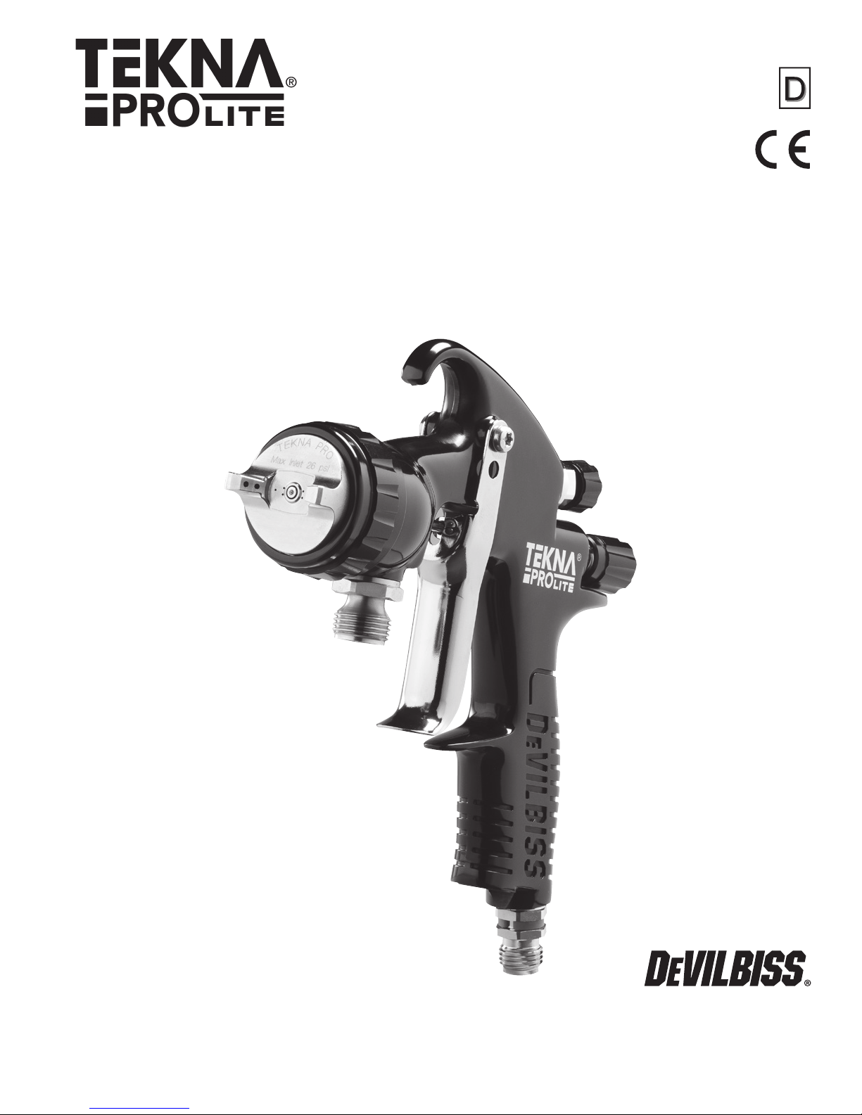
Technical Bulletin
TEKNA Pro Lite Pressure Feed Spraygun
IMPORTANT: Read and follow all instructions and Safety Precautions before using this equipment. Keep
for future use.
EC Declaration of Conformity
We, Finishing Brands UK, Ltd., Ringwood Rd, Bournemouth, Dorset, BH11 9LH, UK, as the manufacturer of the
Spray gun model TEKNA PRO LITE, declare, under our sole responsibility, that the equipment to which this
document relates is in conformity with the following standards or other normative documents:
BS EN 12100 PARTS 1 & 2: 2010, BS EN 1953: 1998+A1:2009; and thereby conform to the
protection requirements of Council Directive 98/37/EEC relating to Machinery Safety Directive, and;
EN 13463-1:2009, council Directive 94/9/EC relating to Equipment and Protective Systems intended
for use in Potentially Explosive Atmospheres protection level II 2 G X.
This product also complies with the requirements of the EPA guidelines, PG6/34. Transfer efciency certicates
are available on request.
TB-1022
D Smith, General Manager
2nd February 2014
The TEKNA Pro Lite complies to ATEX regulations 94/9/EC, protection level II 2 G X, Suitable for use in Zones 1 and 2.
DeVilbiss Automotive Renishing reserves the right to modify equipment specication without prior notice.
Operational Description
The TEKNA Pro Lite spraygun is a lightweight professional gun designed to handle both water-based and solventbased coating materials. Both HVLP and high efciency models are available.
High volume, low pressure (HVLP) models are designed to reduce overspray and provide maximum transfer
efciency by limiting air cap pressure to 0.7 bar (10 psi) (complies with rules issued by SCAQMD and other air
quality authorities).
HVLP models will produce approximately 0.7 bar (10 psi) air cap pressure at 1.2 bar (17 psi) gun inlet pressure
with the trigger pulled. HVLP air cap #HV40 is designed for optimum basecoat and clear coat applications. An
air cap test kit is available (see Accessories) which can be utilized to set the exact air cap pressure.
High efciency models use air cap #TE20 or #TE40. These models are designed to provide optimum
atomization of virtually all waterborne or solvent-based common coating materials at increased application
rates while maintaining very high transfer efciency. High efciency models, when tested under recommended
conditions with automotive renishing materials, have been found to exceed 65% transfer efciency.
IMPORTANT: These guns are not designed for use with highly corrosive and/or abrasive materials and if
used with such materials it must be expected that the need for cleaning and/or replacement of parts will be
increased. If there is any doubt regarding the suitability of a specic material, contact your TEKNA Distributor or
TEKNA direct.
NOTE: This gun is not to be used with halogenated hydrocarbon solvents or cleaning agents such as
1,1,1,-Trichloroethane or methylene chloride. These solvents can react with the aluminium components
used in this gun and cup. The reaction can become violent and lead to an equipment explosion.
3
Page 4
TB-1022
3, 4, 12
2
1
7
15
5
8
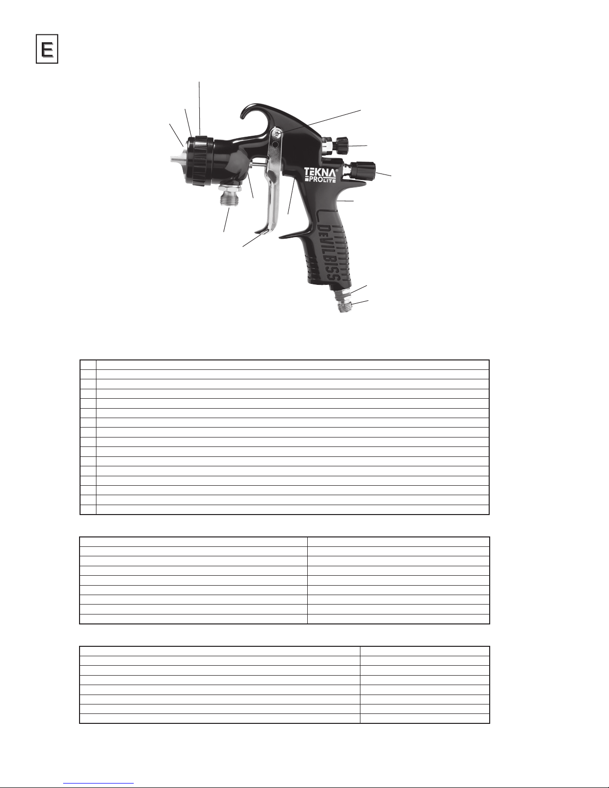
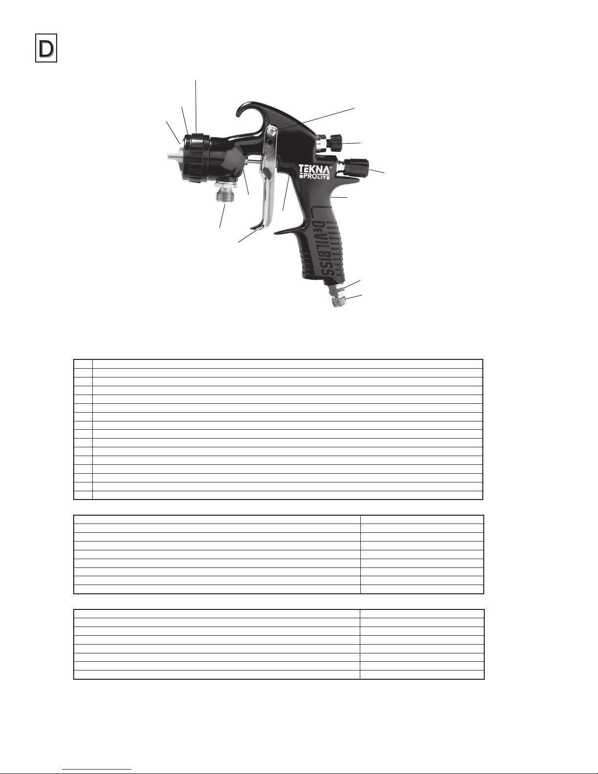
Construction Features
1 Air Cap (nickel plated brass for long durability)
2 Air Cap Retaining Ring (allows easy rotation of air cap)
3 Fluid Nozzle (not visible, ideal for automotive topcoat systems)
4 Fluid Needle (not visible)
5 Fluid Inlet (3/8 BSP thread)
6 Air Inlet (universal thread, accepts G 1/4 & 1/4 NPS)
7 Self Adjusting Needle Packing (packing not visible, for long packing life)
8 Trigger (ergonomic for comfort)
9 Trigger Stud & Screw (easy replacement design)
10 Fan Air Adjustment (stepless regulation for at to round spray)
11 Fluid Adjustment (stepless regulation of uid volume)
12 Removable Spray Head (not visible, for long gun service life)
13 Interchangeable Colour ID System (4 coloured rings supplied)
14 Forged gun body (ergonomic, good looking & durable, easy to clean)
15 Air Valve (not visible) (design offers low pull force & low pressure drop)
16 Gun acceptable for waterborne and solvent borne applications
9
10
11
14
13
6
Materials of Construction
Gun Body Anodized QuickClean®aluminium
Air Cap Nickel plated brass
Fluid Nozzle, Fluid Needle, Fluid Inlet, Trigger Stud Stainless steel
Spray Head, Air Cap Retaining Ring, Knobs, Handle Plug Anodized aluminium
Springs, Clips, Screws Stainless steel
Seals, Gaskets Solvent resistant
Trigger Chrome plated steel
Air Inlet, Body Bushing, Spreader Valve Body, Air Valve Nut Chrome plated brass
Air Valve Assembly Aluminum
Specifications & Technical Data
Air Supply Connection Universal 1/4" BSP and 1/4" NPS
Maximum Static Air Inlet Pressure P1 = 12 bar (175 psi)
Nominal Gun Air Inlet Pressure for HVLP Models – HV40 cap (with gun triggered) 1.2 bar (17 psi) (for compliance)
Nominal Gun Air Inlet Pressure for High Efciency Models – TE40 cap (with gun triggered) 2.0 – 3.5 bar (29 – 50 psi)
Air Consumption See Chart 1 on page 11
Fluid Supply Connection 3/8" BSP
Service Temperature 0 to 40°C (32 to 100°F)
Gun Weight (gun only) 500g (17.6 oz.)
4
Page 5
TB-1022
PROP 65 WARNING
WARNING: This product contains
chemicals known to the State of
California to cause cancer and birth
defects or other reproductive harm.
Safety Precautions
CA PROP
65
This bulletin contains information that is important for you to know and understand. This information relates to USER SAFETY and
PREVENTING EQUIPMENT PROBLEMS. To help you recognize this information, we use the following symbols. Please pay particular
attention to these sections.
NOTE
Important safety information – A hazard that may
cause serious injury or loss of life.
WARNING
CAUTION
Important information that tells how to prevent damage
to equipment, or how to avoid a situation that may cause
minor injury.
Information that you should pay special attention to.
The following hazards may occur during the normal use of this equipment. Please read the following chart before using
this equipment.
HAZARD CAUSE SAFEGUARDS
Fire
Solvent Spray
Solvent and coatings can be highly ammable or
combustible especially when sprayed.
During use and while cleaning and ushing, solvents
can be forcefully expelled from uid and air passages.
Some solvents can cause eye injury.
Adequate exhaust must be provided to keep air free of accumulations of
ammable vapours.
Smoking must never be allowed in the spray area.
Fire extinguishing equipment must be present in the spray area.
Wear eye protection.
Inhaling Toxic Substances
Explosion Hazard –
Incompatible Materials
General Safety
Cumulative Trauma disorders
(“CTD’s”)
CTD’s, or musculoskeletal
disorders, involve damage
to the hands, wrists, elbow,
shoulders, neck and back.
Carpal tunnel syndrome
and tendonitis (such as
tennis elbow or rotator
cuff syndrome) are examples
of CTD’s.
Certain materials may be harmful if inhaled, or if there
is contact with the skin.
Halogenated hydrocarbon solvents – for example;
methylene chloride and 1,1,1,-Trichloroethane are
not chemically compatible with the aluminium that
might be used in many system components. The
chemical reaction caused by these solvents reacting
with aluminium can become violent and lead to an
equipment explosion.
Improper operation or maintenance of equipment. Operators should be given adequate training in the safe use and maintenance of
Use of hand tools may cause cumulative trauma
disorders (“CTD’s”).
CTD’s, when using hand tools, tend to affect the upper
extremities. Factors which may increase the risk of
developing a CTD include:
1. High frequency of the activity.
2. Excessive force, such as gripping, pinching,
or pressing with the hands and ngers.
3. Extreme or awkward nger, wrist, or
arm positions.
4. Excessive duration of the activity.
5. Tool vibration.
6. Repeated pressure on a body part.
7. Working in cold temperatures.
CTD’s can also be caused by such activities as sewing,
golf, tennis, and bowling, to name a few.
Follow the requirements of the Safety Data Sheet supplied by your coating
material manufacturer.
Adequate exhaust must be provided to keep the air free of accumulations of toxic
materials.
Use a mask or respirator whenever there is a chance of inhaling sprayed
materials. The mask must be compatible with the material being sprayed and
its concentration. Equipment must be as prescribed by an industrial hygienist or
safety expert, and be NIOSH approved.
Guns with stainless steel internal passageways may be used with these solvents.
However, aluminium is widely used in other spray application equipment – such
as material pumps, regulators, valves, and cups. Check all equipment items
before use and make sure they can also be used safely with these solvents.
Read the label or data sheet for the material you intend to spray. If in doubt as to
whether or not a coating or cleaning material is compatible, contact your material
supplier.
the equipment (in accordance with the requirements of NFPA-33, Chapter 15).
Users must comply with all local and national codes of practice and insurance
company requirements governing ventilation, re precautions, operation,
maintenance, and housekeeping. These are OSHA Sections 1910.94 and
1910.107 and NFPA-33.
Pain, tingling, or numbness in the shoulder, forearm, wrist, hands, or ngers,
especially during the night, may be early symptoms of a CTD. Do not ignore
them. Should you experience any such symptoms, see a physician immediately.
Other early symptoms may include vague discomfort in the hand, loss of
manual dexterity, and nonspecic pain in the arm. Ignoring early symptoms and
continued repetitive use of the arm, wrist, and hand can lead to serious disability.
Risk is reduced by avoiding or lessening factors 1-7.
5
Page 6
TB-1022
INSTALLATION
For maximum transfer efciency, do not use more pressure than
is necessary to atomise the material being applied.
1. Connect the gun to a clean, moisture and oil free air
supply using a hose size of at least 8 mm (5/16") I.D. hose.
Do not use 6 mm I.D. hose (8 m x 6 mm hose at 510 LPM
has a pressure loss of 1.8 bar. 8 m x 8 mm hose at 510 LPM
has a pressure loss of 0.6 bar. [Do not use 1/4" I.D. hose
(25' x 1/4" hose at 18 CFM has a pressure loss of 25 psi.
25' x 5/16" hose at 18 CFM has a pressure loss of 8 psi).]
Depending on hose length, larger I.D. hose may be required.
NOTE
When gun is triggered on, adjust inlet air pressure
(for recommended pressures see Chart 1 under Parts
Replacement) at the gun inlet. (Pressure gauge shown under
Accessories is recommended for this). Do not use more
pressure than is necessary to atomise the material being
applied. Excess pressure will create additional overspray and
reduce transfer efciency.
NOTE
If quick connects are required, use only high ow quick
connects approved for HVLP use. Other types will not ow
enough air for proper gun operation.
NOTE
If an air adjusting valve is used at the gun inlet, use a DeVilbiss
air adjusting valve. Some competitive adjusting valves have
signicant pressure drop that can adversely affect spray
performance. DeVilbiss air adjusting valves have minimal
pressure drop.
2. Attach the uid supply hose to the uid inlet connector.
NOTE
Protective coating and rust inhibitors have been used
to keep the gun in good condition prior to shipment.
Before using the gun, ush it with solvents so that these
materials will be removed from uid passages.
9. If nish is too wet, reduce uid ow by turning uid adjusting
knob (28) clockwise. If atomisation is too coarse, increase inlet
air pressure. If too ne, reduce inlet pressure.
10. The pattern size can be reduced by turning spreader valve
adjusting knob (16) clockwise.
11. Hold gun perpendicular to surface being sprayed. Arcing
or tilting may result in uneven coating.
12. The recommended spray distance is 150-200 mm (6"–8").
13. Spray edges rst. Overlap each stroke a minimum of 75%. Move
gun at a constant speed.
14. Always turn off air supply and relieve pressure when gun is not
in use.
PREVENTIVE MAINTENANCE & CLEANING
To clean air cap and uid nozzle, brush exterior with a stiff bristle
brush. If necessary to clean cap holes, use a broom straw or
toothpick if possible. If a wire or hard instrument is used, extreme
care must be used to prevent scratching or burring of the holes which
will cause a distorted spray pattern.
To clean uid passages, remove uid supply hose, then ush with a
suitable solvent. Wipe gun exterior with a solvent dampened cloth.
Never completely immerse in solvent as this is detrimental to the
lubricants and packings.
NOTE
When replacing the uid nozzle or uid needle, replace both
at the same time. Using worn parts can cause uid leakage.
See page 11, Chart 2. Also, replace the needle packing at this
time. Lightly lubricate the threads of the uid nozzle before
reassembling. Torque to 18–20 Nm (13–15 ft-lbs). Do not over
tighten the uid nozzle.
CAUTION
To prevent damage to uid nozzle (8) or uid needle (24), be
sure to either 1) pull the trigger and hold while tightening or
loosening the uid nozzle, or 2) remove uid adjusting knob (28)
to relieve spring pressure against needle collar.
OPERATION
1. Mix coating material to manufacturer’s instructions and strain
material.
2. Fill the pressure cup with the required amount of material.
DO NOT OVERFILL.
3. Attach Cup Lid.
4. Turn uid adjusting knob (28) clockwise to prevent uid
needle movement.
5. Turn spreader valve adjusting knob (16) counter clockwise to
fully open.
6. Trigger gun on and adjust inlet air pressure (for
recommended gures see Chart 1 under Parts Replacement)
at the gun inlet. (Pressure gauge shown under Accessories is
recommended for this).
7. Turn uid adjusting knob (28) counter clockwise until rst
thread shows and turn on the supply air to the pressure cup.
8. Test spray. If the nish is too dry, reduce airow by reducing
air inlet pressure.
6
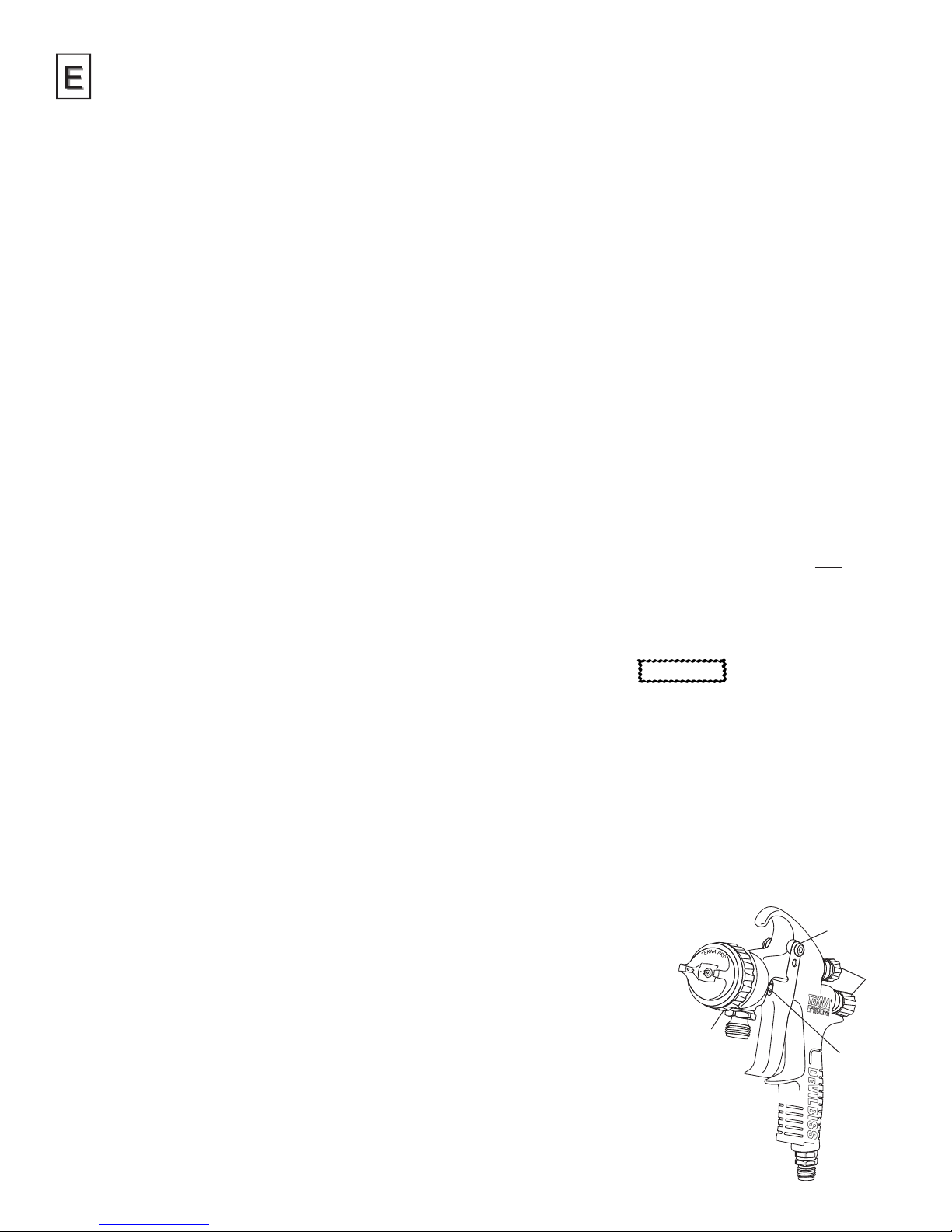
SPRAY GUN LUBRICATION
Daily, apply a drop of spray gun lubricant at trigger stud (40). The
shank of uid needle (24) where it enters packing nut (36) should
also be oiled. Fluid needle packing (34) should be lubricated
periodically. Make sure spray head (9) and air cap retaining ring (1)
threads are clean and free of foreign matter. Before assembling air
cap retaining ring to spray head, clean the threads thoroughly, then
add two drops of spray gun lubricant to threads. Fluid needle spring
(25) and air valve spring (21) should
be coated with a very light grease,
making sure that any excess grease
will not clog the air passages.
Points of Lubrication
A. Trigger Points
B. Packing
C. Adjusting Knobs
D. Air Cap Retaining Ring Threads
D
A
B
C
Page 7
Parts Replacement/
Maintenance
AIR VALVE INSTRUCTIONS
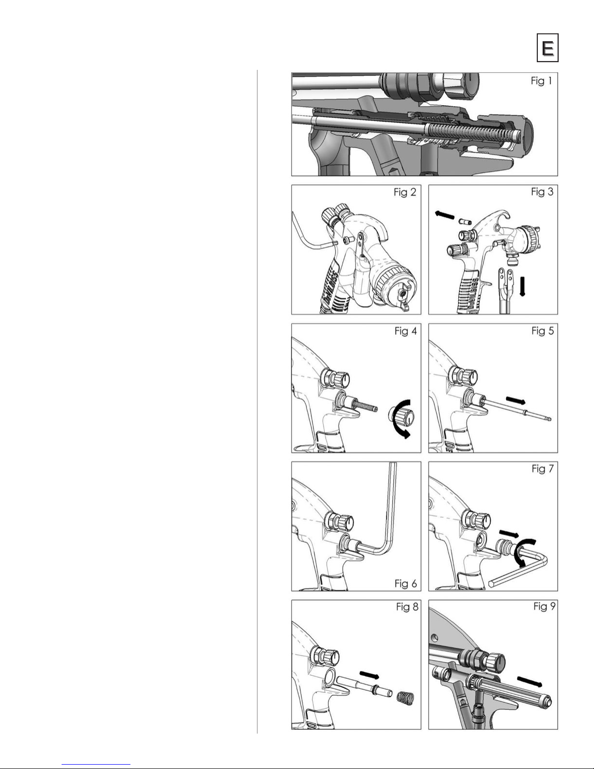
Servicing Air Valve
Reasons to service air valve:
A) Air valve not functioning properly
(may need cleaning).
B) Routine maintenance.
C) Air leaks.
1. Remove trigger screw (38) with Star T20 tool.
(See g 2).
2. Remove trigger stud (40) and remove trigger
(39) (See g 3).
3. Remove uid adjusting knob (28) and spring
(29). (See g 4).
4. Remove uid needle (24) (See g 5).
5. Using a 6mm hex key, remove valve housing
(27). (See Figs 6 and 7).
6. Remove spring (21) and valve spindle (20). (See
Fig 8).
7. Using service tool (44), engage groove behind
the valve seat (19) (See Fig 9).
TB-1022
7
Page 8
TB-1022
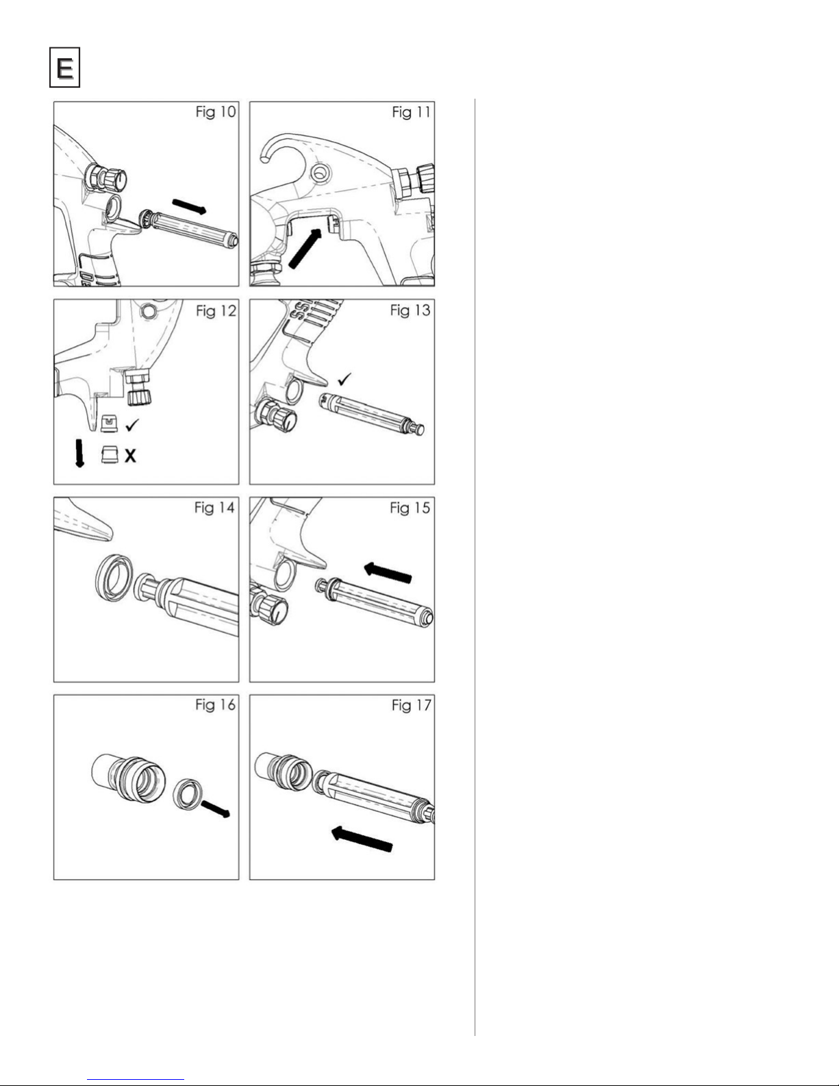
Servicing Air Valve
(continued)
8. Withdraw the valve seat (19) from the gun
body. (See g 10).
9. Push out the front airvalve seal (18) with a
nger. (See g 11).
10. Turn the gun upside down and let the seal fall
out. (See g 12).
11. Fit new front seal (18) to service tool (44). Fit
into gunbody and press rmly to ensure seal is
engaged. (See g 13).
12. Fit a new valve seat (19) to service tool (44).
Groove must face outwards. (See g 14).
13. Fit valve seat (19) to gunbody. (See g 15)
14. Remove rear airvalve seal (22) from housing
(27) with a hooked instrument.(See g 16).
15. Fit new seal(22) to service tool (44). Groove
must face outwards. Press seal (22) to housing
(27). (See g 17)
16. Reassemble remaining parts in reverse
order — valve (20), spring (21), housing (27)
and tighten with 6mm hex key, needle (24)
spring (29) and knob (28). Replace trigger
(39), tting trigger stud (40), screw in the
trigger screw (38) with Star T20 tool.
17. Trigger gun fully and screw in uid adjusting
knob (28) until it stops. Back it off 1/2 turn
and gun will have full needle travel.
18. Trigger gun several times to verify correct
operation.
8
Page 9
Parts Replacement/
Maintenance
NEEDLE PACKING
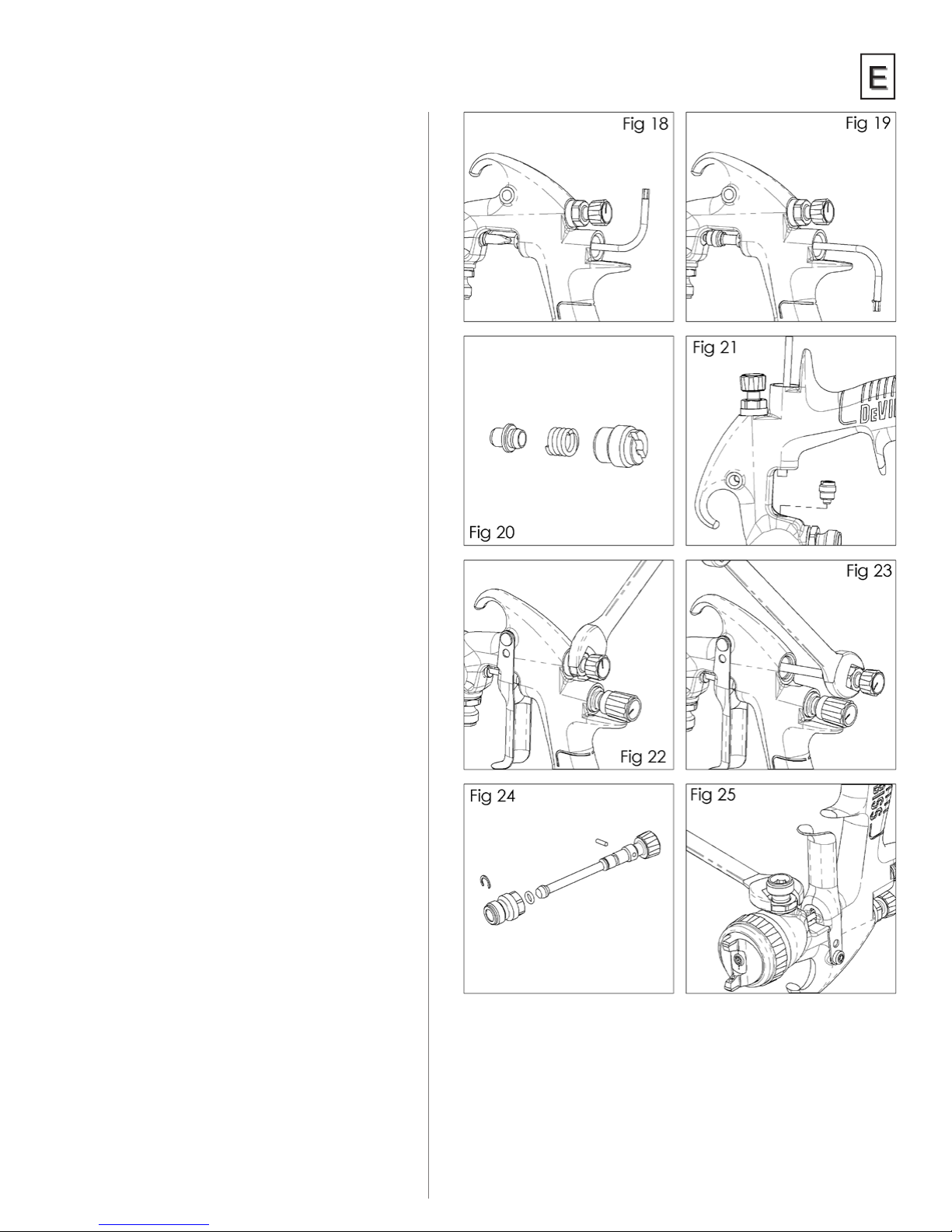
REPLACEMENT INSTRUCTIONS
1. Remove trigger, uid needle, and air valve following
steps 1 to 6 on P7, servicing air valve.
2. Loosen and remove packing nut using a straight
blade screwdriver. (See gs 18 & 19)
3. Discard old packing (34) and packing spring (35)
if replacing. Clean packing if reusing. Also clean
packing spring and nut (36). (See g 20).
4. Re-assemble the packing, assemble into gunbody
by hand and then tighten. (See g 21)
5. Complete re-assembly following steps 16 to 18 on
P8.
TB-1022
SPREADER VALVE ASSEMBLY
REPLACEMENT/MAINTENANCE
The spreader valve assembly can be replaced if damaged.
Remove using a 14 mm wrench
(See gs 22 & 23). The internal seal can be replaced and
is included in the gun rebuild kit (See g 24).
FLUID INLET SEAL
REPLACEMENT INSTRUCTIONS
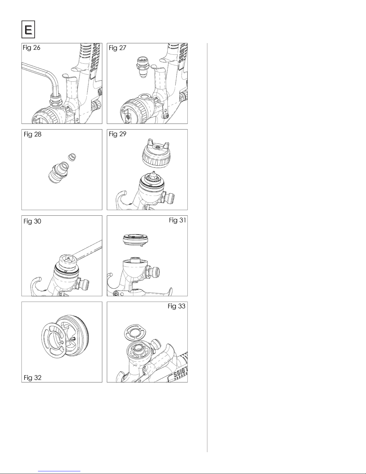
1. Loosen Locknut (46) with 18mm wrench
(See Fig. 25).
2. Unscrew Fluid Inlet Adaptor (47) with 8mm hex key
(See Fig. 26).
3. Remove uid inlet adaptor (See Fig. 27).
4. Remove seal (45) and replace with new seal
(See Fig. 28).
5. Replace uid inlet adaptor (See Fig. 27)
6. Tighten with 8mm hex key to 26-28Nm (20 ft.-lbs.)
(See Fig. 26).
7. Tighten lock nut (46) with 18mm wrench
(See Fig. 25).
9
Page 10
TB-1022
Parts Replacement/
Maintenance
SPRAY HEAD SEAL
REPLACEMENT
1. Remove air cap and retaining ring (6).
(See g 29).
2. Remove uid adjusting knob (28), spring (25),
and spring pad (26). (See g 4, p7).
3. Remove uid needle (24) from gun body. (See
g 5, p7).
4. Remove uid nozzle using a 10mm wrench.
(See g 30).
5. Remove spray head (9) and seal (10)
(See g 31).
6. Remove seal (10) from spray head.
(See g 32).
7. Clean front of gun if required, using a soft
brush, as well as the uid nozzle, air cap, and
retaining ring.
8. Place a new seal (10) into the front of the gun,
making sure the at of the seal is aligned to
the at in the gun. (See g 33).
9. Fit the spray head (9), making sure the pin is
engaged into the hole in the gunbody.
(See g 31).
10. Fit uid nozzle (8), air cap and retaining Ring
(6). Torque the uid nozzle to 18–20 Nm
(13–15 ft-lbs). Do not over torque the uid
nozzle. (See gs 30, and 29)
11. Reassemble remaining parts in reverse order
— uid needle ( 24), needle spring and pad
(29), and uid adjusting knob (28).
12. Trigger gun fully and screw in uid adjusting
knob (28) until it stops. Back it off 1/2 turn
and gun will have full needle travel.
13. Trigger gun several times to verify correct
operation.
10
Page 11
Parts Replacement/Maintenance
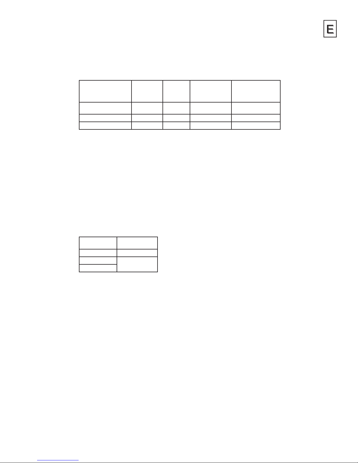
Chart 1 – Air Caps
ORDER NO. FOR
AIR CAP
PRO-103-HV40 HVLP HV40 (1.2) / 17
PRO-103-TE20 High Efciency TE20 (1.8 – 3.5) / 26 – 50 (340 – 550) / 12 – 19.4
PRO-103-TE40 High Efciency TE40 (2.0 – 3.5) / 29 – 50 (368 – 550) / 13 – 19.4
NOTE 1: Guns with HVLP caps must not exceed 0.7 bar (10 psi) air cap pressure with
gun fully triggered. (Aproximately 17 psi gun inlet pressure.) (See accessories
for air cap test kit which is available to set the exact cap pressure.)
When used with high efciency caps and Automotive Renishing materials,
these spray guns have been found to exceed 65% transfer efciency under
recommended conditions.
TECHNOLOGY MARKING
ON AIR CAP
NOMINAL
OPERATING GUN
INLET PRESSURE
BAR/PSI
(for compliance)
AIR FLOW
LPM/SCFM
(298) / 10.5
TB-1022
NOTE 2: When removing air cap from retaining ring, don’t remove slip ring (2)
or retaining ring seal (5) from retaining ring. Damage to the parts may
occur. Slip ring and retaining ring seal are not available as replacements.
Simply wipe parts clean and reassemble with new or clean air cap.
Chart 2 – Fluid Nozzles & Fluid Needles
PART NO. ON
FLUID NOZZLE
PRO-205-10-K PRO-320-085-10K
PRO-205-12-K
PRO-205-14-K
NOTE: When replacing the uid nozzle or uid needle, replace both at the same time.
Lightly lubricate the threads of the uid nozzle before reassembling. Torque
to 18–20 Nm (13–15 ft-lbs). Don’t over tighten the uid nozzle. Use 10 mm
wrench supplied with gun.
PART NO. ON
FLUID NEEDLE
PRO-320-12-14-K
11
Page 12
TB-1022
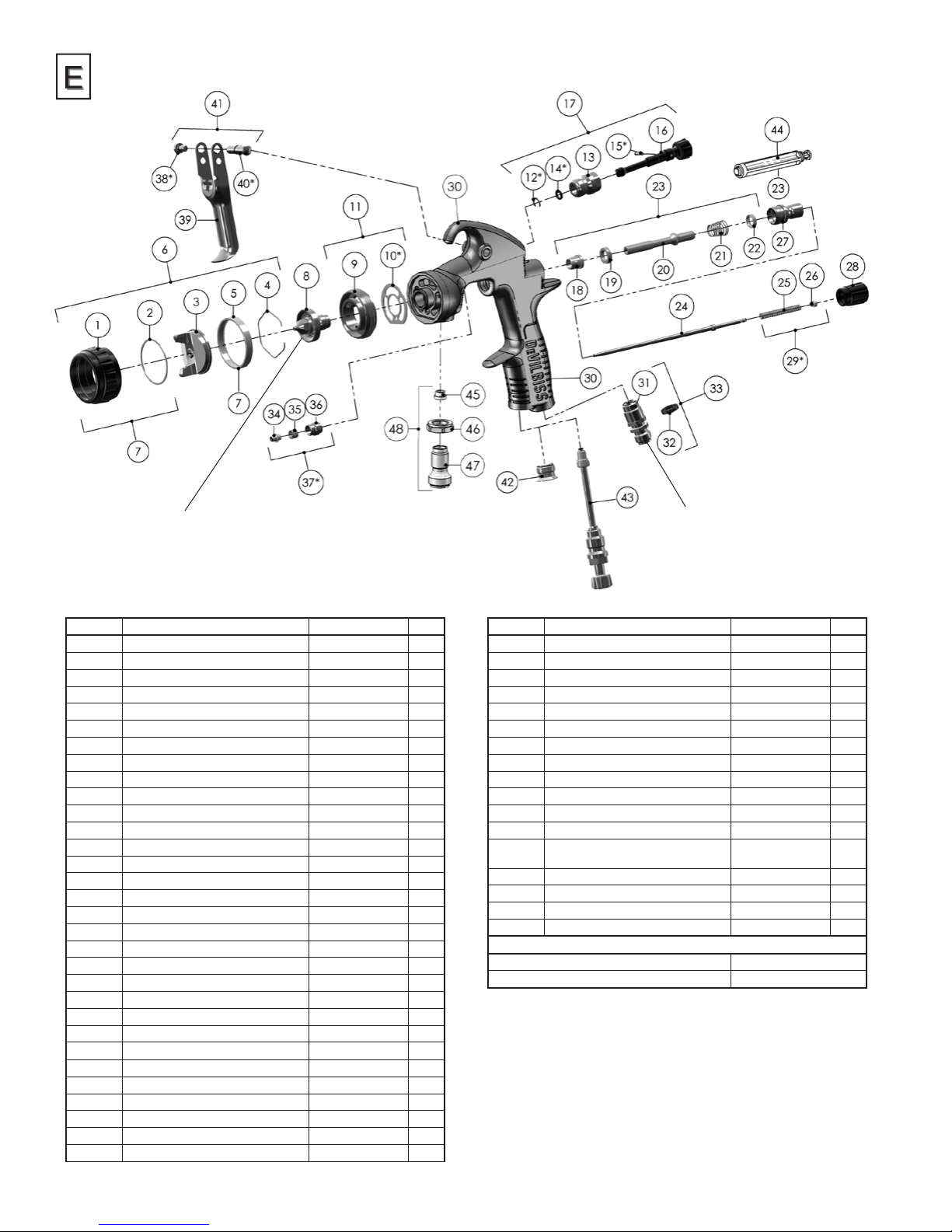
Fluid Nozzle
Torque to 13–15 ft-lbs (18–20 Nm)
REF. NO. DESCRIPTION PART NO. QTY
1 Air Cap Retaining Ring 1
2 Slip Ring 1
3 Air Cap 1
4 Air Cap Retaining Clip JGA-156-K10 1
5 Retaining Ring Seal 1
6 Aircap & Ring See chart 1 p11 1
7 Air Cap Retaining Ring & Seals 702725 1
8 Fluid Nozzle See chart 2 p11 1
9 Spray head 1
*10 Spray head Seal 702726 1
11 Spray head kit SN-69-K 1
*12 Circlip 1
13 Valve Body 1
*14 O Ring 1
*15 Spreader Valve Pin 1
16 Spreader Valve Adjusting Knob 1
17 Spreader Valve Assembly PRO-408-BL-K 1
18 Front Valve Seal 1
19 Valve Seat 1
20 Spindle 1
21 Air Valve Spring 1
22 Rear Valve Seal 1
23 Air Valve Kit 703530 1
24 Fluid Needle See chart 2 p11 1
25 Needle Spring 1
26 Spring Pad 1
27 Housing & Seal Kit SN-66-K 1
28 Fluid Adjusting Knob SN-67-BK-K 1
*29 Needle Spring Kit PRO-472-K3 1
30 Gunbody 1
31 Air Inlet 1
Air Inlet
Torque to 15 ft-lbs (20 Nm)
Use medium strength thread sealant
(i.e. Devcon #2242 Blue or equivalent)
on threads
REF. NO. DESCRIPTION PART NO. QTY
32 Colour ID Ring Kit (4 Colours) 702735 1
33 Air Inlet Kit 702734 1
34 Needle Packing 1
35 Packing Spring 1
36 Packing Nut 1
*37 Packing, Spring and Packing Nut Kit 702731 1
*38 Trigger Screw 1
39 Trigger 1
*40 Trigger Stud 1
41 Trigger, Stud & Screw Kit SP-617-CR-K 1
42 Plug 1
43 Cheater Valve (optional) 702737 1
44 Air Valve Service Tool (only included in
the Air Valve Kit 23)
45 Seal 1
46 Lock Nut 1
47 Fluid Inlet 1
48 Fluid Inlet Kit ADV-7-K 1
SERVICE PARTS
Spray Gun repair kit (includes items marked *) PRO-470
Seal and Pin Kit, kit of 5 (items 12, 14 and 15) GTI-428-K5
12
Page 13

Troubleshooting Possible Problems in Operation
CONDITION CAUSE CORRECTION
Heavy top or
bottom pattern
Horn holes plugged.
Obstruction on top or bottom of fluid tip.
Cap and/or tip seat dirty.
Clean. Ream with non-metallic point.
Clean.
Clean.
TB-1022
Heavy right or left
side pattern
Heavy center pattern
Split spray pattern
Jerky or fluttering spray
Unable to get round spray
Will not spray
Starved spray pattern
Excessive overspray
Excessive fog
Dry spray
Fluid leaking from packing nut
Fluid leaking or dripping from
front of gun
*Most common problem.
Left or right side horn holes plugged.
Dirt on left or right side of fluid tip.
Remedies for the top-heavy, bottom-heavy, right-heavy, and left-heavy patterns:
1. Determine if the obstruction is on the air cap or the fluid tip. Do this by making a test spray
pattern. Then, rotate the cap one-half turn and spray another pattern. If the defect is inverted,
obstruction is on the air cap. Clean the air cap as previously instructed.
2. If the defect is not inverted, it is on the fluid tip. Check for a fine burr on the edge of the fluid tip.
Remove with #600 wet or dry sand paper.
3. Check for dried paint just inside the opening; remove by washing with solvent.
Fluid flow too high for atomization air.
Material flow exceeds air cap's capacity.
Spreader adjustment valve set too low.
Atomizing pressure too low.
Material too thick.
Atomization air pressure too high.
Fluid flow too low.
Spreader adjusting valve set too high.
*Loose or damaged fluid tip/seat.
Baffle seal not installed correctly.
Material level too low.
Container tipped too far.
Obstruction in fluid passage.
Dry or loose fluid needle packing nut.
Spreader adjustment screw not seating
properly.
Air cap retaining ring loose.
No air pressure at gun.
Fluid needle adjusting screw not open enough.
Fluid too heavy for suction feed.
Fluid pressure too low.
Inadequate material flow.
Low atomization air pressure.
Too much atomization air pressure.
Gun too far from work surface.
Improper stroking (arcing, gun motion
too fast).
Too much or too fast-drying thinner.
Too much atomization air pressure.
Air pressure too high.
Gun tip too far from work surface.
Gun motion too fast.
Gun out of adjustment.
Packing nut loose.
Packing worn or dry.
Packing nut too tight.
Dry packing.
Fluid tip or needle worn or damaged.
Foreign matter in tip.
Fluid needle spring broken.
Wrong size needle or tip.
Clean. Ream with non-metallic point.
Clean.
Balance air pressure and fluid flow. Increase spray
pattern width with spreader adjustment valve.
Thin or lower fluid flow.
Adjust.
Increase pressure.
Thin to proper consistency.
Reduce at transformer or gun.
Increase fluid flow (increases gun handling speed).
Adjust.
Tighten or replace.
Install per directions.
Refill.
Hold more upright.
Backflush with solvent.
Lubricate or tighten.
Clean or replace.
Tighten.
Check air supply and air lines, blow out gun air
passages.
Open fluid needle adjusting screw.
Thin material and/or change to larger tip size, or
pressure feed.
Increase fluid pressure at tank.
Back fluid adjusting screw out to first thread,
or change to larger tip size, or increase fluid
pressure at tank.
Increase air pressure and rebalance gun.
Reduce pressure.
Adjust to proper distance.
Move at moderate pace, parallel to work surface.
Remix properly.
Reduce pressure
Reduce air pressure.
Adjust to proper distance.
Slow down.
Adjust.
Tighten, do not bind needle.
Replace or lubricate.
Adjust.
Lubricate.
Replace tip and needle.
Clean.
Replace.
Replace.
13
Page 14
TB-1022
Troubleshooting Possible Problems in Operation (cont'd)
CONDITION CAUSE CORRECTION
Runs and sags
Thin, sandy coarse finish drying
before it flows out
Thick, dimpled finish
"orange peel"
Too much material flow.
Material too thin.
Gun tilted on an angle, or gun motion
too slow.
Gun too far from surface.
Too much air pressure.
Improper thinner being used.
Gun too close to surface.
Too much material coarsely atomized.
Air pressure too low.
Improper thinner being used.
Material not properly mixed.
Surface rough, oily, dirty.
Adjust gun or reduce fluid flow.
Mix properly or apply light coats.
Hold gun at right angle to work and adapt to proper
gun technique.
Check distance. Normally approximately 6–8".
Reduce air pressure and check spray pattern.
Follow paint manufacturer's mixing instructions.
Check distance. Normally approximately 6–8".
Follow paint manufacturer's mixing instructions.
Increase air pressure or reduce fluid flow.
Follow paint manufacturer's mixing instructions.
Follow paint manufacturer's mixing instructions.
Properly clean and prepare.
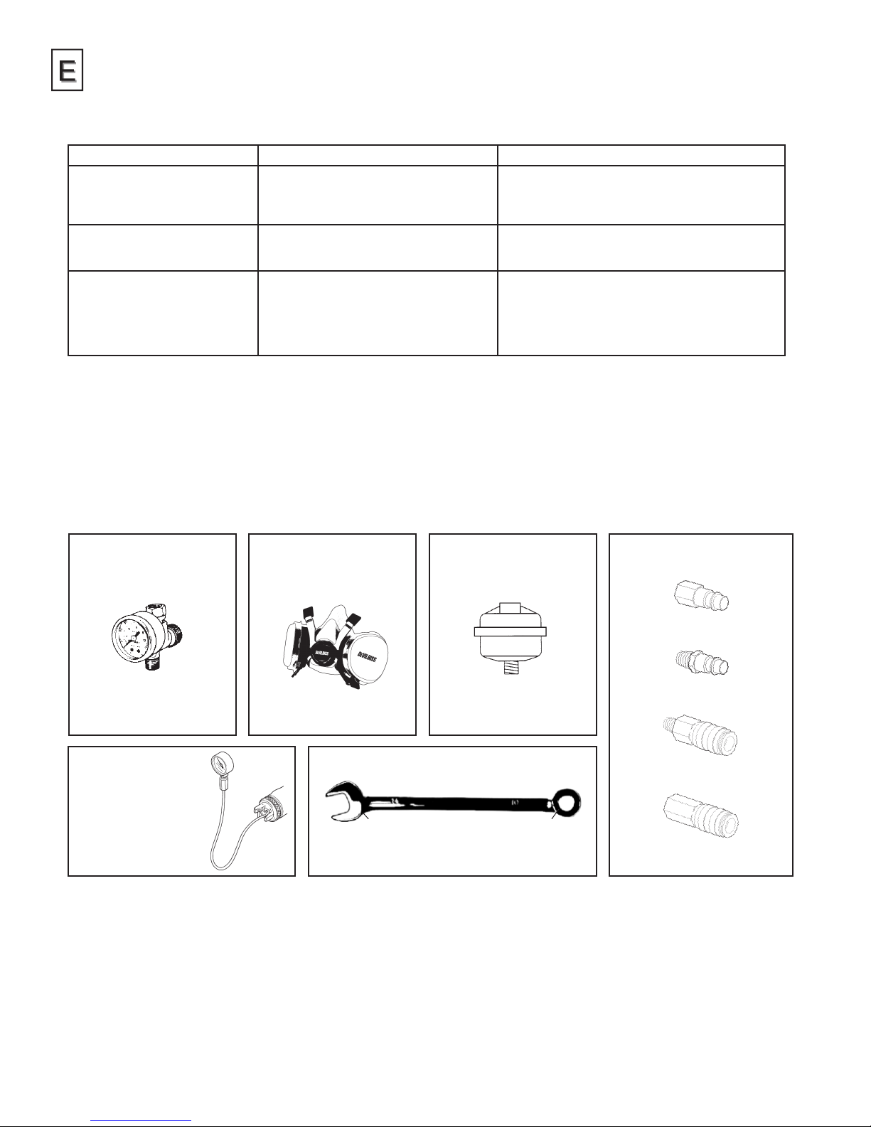
Accessories
HAV-500 OR
HAV-511
Adjusting Valve
(HAV-511 SHOWN)
HAV-500 does not have pressure gauge. Use to control air
usage at gun.
703625
HV40 Air Cap Test Kit
The purpose of this test
kit is to measure air cap
atomizing air pressure at
the center air port of the air
cap. Used to confirm code
compliance and as a daily
quality control measure.
Champion™
Disposable Respirator
803611 (Medium)
803612 (Large)
NIOSH-Certified for respiratory protection.
14 mm 10 mm
HAF-507 Whirlwind™
In-Line Air Filter
Removes water, oil, and
debris from the air line.
702740 TEKNA Wrench
For maintenance use.
Industrial Quick Connects
For HVLP Guns (Air)
HC-4419 Stem
1/4" NPT(F)
HC-1166 Stem
1/4" NPT(M)
HC-4719 Coupler
1/4" NPT(M) /NPS(M)
HC-4720 Coupler
1/4" NPT(F)
14
Page 15

WARRANTY
This product is covered by DeVilbiss' 2 Year Limited Warranty.
DeVilbiss Sales and Service: www.devilbiss.com
DeVilbiss
DeVilbiss has authorized distributors throughout the world.
For equipment, parts and service, check the Yellow Pages.
For technical assistance, see listing below.
This product is manufactured in the UK by:
Finishing Brands UK, Ltd.
Ringwood Road,
Bournemouth,
BH11 9LH, UK
Distributed exclusively in North America by:
DeVilbiss
TB-1022
3/16 ©2016 DeVilbiss. All rights reserved. Printed in U.S.A.
15
Page 16
TB-1022
WARRANTY POLICY
DeVilbiss products are covered by Finishing Brands two year materials and workmanship limited warranty. The use of any parts or
accessories, from a source other than Finishing Brands, will void all warranties. For specic warranty information please contact the closest
Finishing Brands location listed below.
Finishing Brands reserves the right to modify equipment specifications without prior notice. DeVilbiss®, Ransburg®, BGK®, and
Binks® are registered trademarks of Carlisle Fluid Technologies, Inc., dba Finishing Brands. ©2016 Carlisle Fluid Technologies, Inc.,
dba Finishing Brands. All rights reserved.
DeVilbiss is a Carlisle Fluid Technologies Company, a global leader in innovative spray nishing
technologies. For technical assistance or to locate an authorized distributor, contact one of our
sales and customer support locations below.
USA/Canada
www.devilbiss.com
ghcustserv@carlisleft.com
Toll Free Tel: 1-800-992-4657
Toll Free Fax: 1-877-790-6965
© 2016 DeVilbiss. All rights reserved. 3/16
Page 17
TB-1022
Ersetzt TB-1022
Technisches
Bulletin
Fließbecher-Spritzpistole
für Druck
Reparturset
für Spritzpistole
PRO-470
ghcustserv@carlisleft.com
800.992.4657
www.devilbiss.com
Page 18

TB-1022
Inhaltsverzeichnis
Thema Seite
EG-Konformitätserklärung ......................................................................................................................................3
Funktionsbeschreibung ............................................................................................................................................3
Konstruktionsmerkmale und -werkstoffe .......................................................................................................4
Technische Daten und Spezikationen
Sicherheitsmaßnahmen .......................................................................................................................................... 5
Installation, Betrieb, vorbeugende Wartung und Reinigung .................................................................6
Spritzpistolenschmierung
Teileaustausch/Wartung ................................................................................................................................ 7–12
A) Luftventil warten ................................................................................................................................ 7–8
B) Nadeldichtung, Strahlregulierventil, Fluideinlass Dichtung .............................................. 9
C) Sprühkopf-Dichtungsersatz ............................................................................................................ 10
D) Tabelle 1 – Luftkappen .......................................................................................................................11
Tabelle 2 – Flüssigkeitsdüsen und -nadeln
E) Explosionsdarstellung und Teileliste .......................................................................................... 12
Fehlersuche bei möglichen Betriebsproblemen ..............................................................................13–14
Zubehör ....................................................................................................................................................................... 14
Garantie .........................................................................................................................................................................15
Bei Verwendung mit der HVLP-Kappe kann diese Spritzpistole in
allen Pichtzonen eingesetzt werden—in vorgeschriebenen HVLPPichtzonen sowie nicht regulierten Bereichen.
Wenn mit hohem Wirkungsgrad Kappen und "Automotive
Renishing" Materialien sind diese Pistolen wurde festgestellt,
dass 65% Transferefzienz unter den empfohlenen Bedingungen
überschreiten.
Wenden Sie sich an Ihre behörde zur Überwachung
der Luftqualität vor Ort, wenn Sie Fragen zu HVLP oder
Konformitätsanforderungen in Ihrer Pichtzone haben.
2
HINWEIS:
Page 19
Technisches Bulletin
Fließbecher-Spritzpistole für Druck
WICHTIG: Bitte lesen und befolgen Sie alle Anweisungen und Sicherheitsvorschriften vor Verwendung
dieser Ausrüstung. Bitte zur späteren Bezugnahme aufbewahren.
EG-Konformitätserklärung
Finishing Brands UK, Ltd., Ringwood Rd, Bournemouth, Dorset, BH11 9LH, UK, ist der Hersteller der Spritzpistole,
Modell TEKNA PRO LITE, und erklärt hiermit als Alleinverantwortlicher, dass die Ausrüstung, auf die sich dieses
Dokument bezieht, den nachfolgend aufgeführten Normen oder anderen wesentlichen Dokumenten gerecht wird:
BS EN 12100 TEILE 1 & 2: 2010, BS EN 1953: 1998+A1:2009; und somit den Schutzanforderungen der
Richtlinie 98/37/EEC bezüglich der Maschinensicherheitsrichtlinie und
EN 13463-1:2009, Richtlinie 94/9/EC für Geräte und Schutzsysteme zur bestimmungsgemäßen
Verwendung in explosionsgefährdeten Bereichen Stufe II 2 G X entspricht.
Dieses Produkt entspricht auch den Anforderungen der EPA-Richtlinie PG6/34. Auf Anforderung können auch die
Übertragungsratenzertikate vorgelegt werden.
TB-1022
D Smith, General Manager
2. Februar 2014
Die TEKNA Pro Lite-Fließbecher-Spritzpistolenausrüstung entspricht der Explosionsschutzrichtlinie (ATEX)
94/9/EG, Schutzgrad II 2 G X, geeignet für Zone 1 und 2.
DeVilbiss Automotive Renishing behält sich das Recht vor, Änderungen ohne vorherige Mitteilung vorzunehmen.
Funktionsbeschreibung
Bei der TEKNA Pro Lite-Spritzpistole handelt es sich um eine leichte, gewerbliche Pistole zum Umgang mit auf Wasser basierenden
und lösungsmittelhaltigen Anstrichstoffen. Sowohl HVLP- als auch Hochleistungsmodelle stehen zur Wahl. Mit den HVLP-Modellen
(High Volume, Low Pressure = Hohes Volumen, Niederdruck) wird Overspray reduziertund maximale Übertragungsleistung
erbracht, indem der Luftkappendruck auf 0,7 bar (10 psi) begrenzt wird (erfüllt die von SCAQMD und anderen
Luftqualitätsbehörden erlassenen Regeln).
Bei gezogenem Abzugshebel produzieren HVLP-Modelle einen Luftkappendruck von ca. 0,7 bar (10 psi) bei einem
Pistoleneingangsdruck von 1,2 bar (17 psi). Die HVLP-Luftkappe #HV40 ist für optimalen Grundlackauftrag und optimalen
Klarlackauftrag konzipiert. Es gibt eine Luftkappen-Prüfset verfügbar (siehe Zubehör), mit denen der exakte Luftkappendruck
eingestellt werden kann.
Hochleistungsmodelle verwenden die Luftkappe #TE20 oder #TE40. Diese Modelle bieten optimale Zerstäubung praktisch
aller üblichen, auf Wasser basierenden oder lösungsmittelhaltigen Anstrichstoffe bei erhöhten Aufwandmengen und sehr
hoher, konstanter Übertragungsleistung. Tests unter den empfohlenen Bedingungen mit Autolacken haben ergeben, dass
Hochleistungsmodelle 65% Übertragungsleistung überschreiten.
WICHTIG: Diese Spritzpistolen eignen sich nicht für den Einsatz von stark korrosiven und/oder abreibenden Materialien. Bei
Einsatz solcher Stoffe muss davon ausgegangen werden, dass der Aufwand für die Reinigung bzw. der Bedarf an Ersatzteilen
zunimmt. Wenn Sie nicht genau wissen, ob ein bestimmtes Material geeignet ist, wenden Sie sich bitte an Ihren örtlichen TEKNA-
Händler oder direkt an TEKNA selbst.
HINWEIS: Diese Spritzpistole ist nicht für den Einsatz mit halogeniertem Kohlenwasserstoff oder Reinigungsmitteln
wie Methylendichlorid und 1,1,1,-Trichloräthan geeignet. Solche Lösungsmittel können mit den in dieser Spritzpistole
und dem Becher verwendeten Aluminiumteilen reagieren. Die entstehende Reaktion kann sehr stark sein und zu einer
Explosion des Geräts führen.
3
Page 20
TB-1022
3, 4, 12
2
9
1
10
11
7
14
15
5
8
13
6
Baumerkmale
1 Luftkappe (Messing, vernickelt, daher lange Lebensdauer)
2 Haltering, Luftkappe (gewährleistet einfache Drehung der Luftkappe)
3 Flüssigkeitsdüse (nicht sichtbar, ideal für Auto-Decklacksysteme)
4 Farbnadel (nicht sichtbar)
5 Materialeinlass (3/8 BSP Gewinde)
6 Lufteinlass (Universalgewinde, für G 1/4 & 1/4 NPS geeignet)
7 Selbstregulierende Nadeldichtung (Dichtungspackung nicht sichtbar, optimal lange Lebensdauer)
8 Fingerabzug (ergonomisch konstruiert, daher äußerst bequem zu handhaben)
9 Bolzen mit Schraube (sehr einfach auszutauschen)
10 Gebläselufteinstellung (stufenlose Regelung für Rundumspray)
11 Flüssigkeitseinstellung (stufenlose Regelung des Flüssigkeitsvolumens)
12 Entfernbarer Sprühkopf (nicht sichtbar, zur Erzielung einer langen Spritzpistoleneinsatzdauer)
13 Austauschbares Farb-ID-System (4 Farbringe werden mitgeliefert)
14 Pistolengehäuse (ergonomisch konstruiert, gutes Design, dauerhaft, leicht zu reinigen)
15 Luftventil (niedrige Zugkraft und geringer Druckabfall dank des vorzüglichen Designs)
16 Spritzpistole für wasserlösliche und auf Lösungsmittel basierende Einsätze geeignet
Werkstoffe
Spritzpistolengehäuse Aluminium, eloxiert QuickClean®
Luftkappe Messing, vernickelt
Flüssigkeitsdüse, Farbnadel, Materialeinlass, Fingerabzugsbolzen Edelstahl
Sprühkopf, Luftkappenhaltering, Knöpfe, Griffschraube Aluminium, eloxiert
Federn, Klammern, Schrauben Edelstahl
Dichtungen Lösungsmittelbeständig
Fingerabzug Stahl, verchromt
Lufteinlass, Gehäusebuchse, Regulierventilgehäuse, Luftventilmutter Messing, verchromt
Luftlter Aluminium
Technische Daten und Spezifikationen
Druckluftanschluss Universal 1/4” BSP und 1/4” NPS
Statischer Einlassluftdruck, max. P1 = 12 bar (175 psi)
Nominaler Lufteinlassdruck der Spritzpistole für HVLP-Modelle, HV40-Spritzpistolengehäuse (bei abgezogener Spritzpistole)
Nominaler Lufteinlassdruck der Spritzpistole für Hochleistungsmodelle, TE40-Spritzpistolengehäuse (bei abgezogener Spritzpistole)
Luftverbrauch Siehe Tabelle 1 auf Seite 11
Flüssigkeitsanschluss 3/8” BSP
Betriebstemperaturbereich 0 bis 40°C (32 bis 100°F)
Pistolengewicht (nur Pistole) 500 g (17.6 Unzen)
1,2 bar (17 psi) (für Konformität)
2,0 – 3,5 bar (29 – 50 psi)
4
Page 21

TB-1022
PROP 65 WARNUNG
WARNUNG: Dieses Produkt enthält Chemikalien,
die im Bundesstaat Kalifornien Krebs und
Geburtsschäden oder andere reproduktive
Schäden verursachen.
Sicherheitsmaßnahmen
CA PROP
65
Dieses Bulletin umfasst Informationen, die Sie lesen und verstehen müssen. Die aufgeführten Informationen beziehen sich auf
BETRIEBSSICHERHEIT und VERMEIDUNG VON AUSRÜSTUNGSPROBLEMEN. Zum besseren Verständnis dieser Informationen verwenden wir
die folgenden Symbole: Bitte lesen Sie sich diese Abschnitte mit größter Sorgfalt durch.
WARNUNG
Wichtige Sicherheitsinformationen für mögliche
Gefahren, die zu schweren Verletzungen oder sogar Tod
führen können.
VORSICHT
Wichtige Informationen, die Ihnen erklären, wie man Schäden an der
Ausrüstung oder Situationen vermeiden kann, die zu leichten Verletzungen
führen würden.
HINWEIS
Informationen, die Sie genauer
beachten sollten.
Während des normalen Einsatzes dieser Ausrüstung können die nachfolgend beschriebenen Gefahren auftreten. Bitte lesen Sie vor
Einsatz dieser Ausrüstung die nachfolgende Tabelle durch.
GEFAHR URSACHE SICHERHEITSMASSNAHMEN
Feuer
Lösungsmittelspray
Lösungsmittel und Lacke können sehr leicht entammbar
oder brennbar sein, vor allen Dingen beim Sprühen.
Beim Einsatz und Reinigen sowie Spülen können
Lösungsmittel plötzlich aus Flüssigkeits- und Luftleitungen
ausgestoßen werden. Einige Lösungsmittel können zu
Augenverletzungen führen.
Um die Luft frei von Ansammlungen entzündbarer Dämpfe zu halten,
muss der Bereich immer gut entlüftet werden.
Rauchen ist im Sprühbereich immer verboten.
Feuerlöschanlagen müssen immer im Sprühbereich vorgesehen
werden.
Schutzbrille tragen.
Einatmen von Giftstoffen
Explosionsgefahr nicht kompatible Stoffe
Allgemeine Sicherheit
Kumulative traumatische
Erkrankungen (CTDs)
Kumulative traumatische
Erkrankungen (CTDs - Cumulative
Trauma Disorders) oder MuskelSkelett-Beschwerden einschl.
Beschwerden an Händen,
Handgelenken, Ellbogen,
Schultern, Nacken und Rücken.
Karpaltunnelsyndrom (KTS) und
Sehnenscheidenentzündungen
(wie Tennisarm oder
Rotatorenmanschettensyndrom)
sind Beispiele
von CTDs.
Bestimmte Stoffe sind schädlich, wenn sie eingeatmet
werden oder in Kontakt mit der Haut kommen.
Halogenisierte Kohlenwasserstoff-Lösungsmittel – zum
Beispiel: Methylendichlorid und 1,1,1,-Trichloräthan sind
nicht chemisch kompatibel mit Aluminium, das in vielen
Systemteilen Einsatz ndet. Die chemische Reaktion, die
erzeugt wird, wenn diese Lösungsmittel mit Aluminium
reagieren, kann sehr stark sein und zu einer Explosion der
Ausrüstung führen.
Falscher Betrieb oder falsche Wartung der Ausrüstung Das Bedienungspersonal muss gründlich für den sicheren Einsatz und
Die Verwendung von Handwerkzeugen kann CTDs
(kumulative traumatische Erkrankungen) verursachen.
CTD wirkt sich bei Verwendung von Handwerkzeugen
auf die oberen Extremitäten aus. Die folgenden Faktoren
können das Risiko von CTDs erhöhen:
1. Große Häugkeit dieser Tätigkeit.
2. Übermäßiger Krafteinsatz wie Greifen, Klemmen oder
Drücken mit Händen und Fingern.
3. Extreme oder ungewöhnliche Finger-, Handgelenk- oder
Armbewegungen.
4. Überlange Dauer dieser Tätigkeit.
5. Vibration des Werkzeugs.
6. Wiederholter Druck auf ein Körperteil.
7. Arbeiten bei niedrigen Temperaturen.
CTDs können außerdem durch Aktivitäten wie Nähen, Golf,
Tennis, Bowling und viele andere mehr verursacht werden.
Befolgen Sie alle Empfehlungen des Sicherheitsdatenblattes (SDS),
die vom Lackhersteller zur Verfügung gestellt wird.
Um die Luft frei von Ansammlungen von Giftstoffen zu halten, muss der
Bereich immer gut entlüftet werden.
Wenn die Möglichkeit besteht, dass Sprühmaterial eingeatmet wird, müssen
Sie eine Maske oder einen anderen Atemschutz tragen. Die Maske muss
mit dem gesprühten Material und seiner Konzentration kompatibel sein. Die
entsprechenden Ausrüstungen müssen von Sicherheitsexperten genehmigt
sein und NIOSH oder gleichwertig entsprechen.
Für solche Lösungsmittel können Spritzpistolen mit internen
Leitungen aus Edelstahl verwendet werden. Aluminium wird jedoch
häug in anderen Sprühausrüstungen verwendet – zum Beispiel
Materialpumpen, Regler, Ventile usw. Prüfen Sie alle Anlagenteile vor
dem Einsatz und stellen Sie sicher, dass sie mit diesen Lösungsmitteln
verwendet werden können. Lesen Sie das Etikett oder Datenblatt
für das Material, das gesprüht werden soll. Wenn Sie Zweifel haben,
ob ein Lack oder Reinigungsmittel kompatibel ist, fragen Sie das
Lieferunternehmen des betreffenden Materials.
die vorschriftsmäßige Wartung der Ausrüstung ausgebildet werden
(gemäß NFPA-33, Kapitel 15, oder gleichwertig). Benutzer müssen
alle Vorschriften geltender lokaler und nationaler Bestimmungen
sowie Erfordernisse seitens Versicherungen bezüglich Entlüftung,
Feuerschutz, Betrieb, Wartung und Instandhalten einhalten. Dabei sind
alle Bestimmungen wie OSHA, Abschnitt 1910.94 und 1910.107 sowie
NFPA-33 und ähnliche Vorschriften zu beachten.
Schmerzen, Kribbeln oder Taubheit in Schulter, Vorderarm, Handgelenk,
Händen oder Fingern, vor allen Dingen nachts, können erste Anzeichen
einer CTD sein. Lassen Sie diese Symptome nicht unbeachtet. Wenn
Sie solche Symptome feststellen, suchen Sie bitte sofort einen Arzt auf.
Andere frühe Symptome sind leichte Beschwerden in der Hand, ein
Abnehmen der Fingerfertigkeit sowie nicht spezische Schmerzen im
Arm. Ein Ignorieren früher Warnzeichen und lang anhaltende monotone
Verwendung von Arm, Handgelenk und Hand können zu ernsten
Beschwerden führen. Das Risiko wird verringert, indem Sie die Faktoren
1 bis 7 ausschalten oder herabsetzen.
5
Page 22

TB-1022
AUFSTELLUNG
Zur Erzielung des optimalen Auftragswirkungsgrads verwenden Sie
niemals mehr Druck, als zum Zerstäuben des verwendeten Materials
erforderlich ist.
1. Schließen Sie die Spritzpistole an einer sauberen feuchtigkeitsund ölfreien Druckluftversorgung an. Verwenden Sie dazu eine
Schlauchgröße von mindestens 8 mm Innendurchmesser. Verwenden
Sie niemals einen Schlauch mit 6 mm Innendurchmesser. (Ein 8 m x 6
mm Schlauch zeigt bei 510 l/min einen Druckverlust von 1,8 bar.) Ein
8 m x 8 mm Schlauch zeigt bei 510 l/min einen Druckverlust von 0,6
bar. [Verwenden Sie keinen Schlauch mit 1/4” Innendurchmesser. (Ein
25’ x 1/4” Schlauch zeigt bei 18 CFM einen Druckverlust von 25 psi.)
Ein 25’ x 5/16” Schlauch zeigt bei 18 CFM einen Druckverlust von 8
psi.)] Je nach Schlauchlänge kann es vorkommen, dass ein Schlauch
mit größerem Innendurchmesser notwendig ist.
HINWEIS
Bei abgezogener Pistole den Lufteinlassdruck (empfohlene
Druckwerte können in Tabelle 1 unter Teileaustausch nachgelesen
werden) am Pistoleneinlass einstellen. (der unter Zubehör gezeigte
Luftdruckmesser wird dafür empfohlen). Nicht mehr Druck als
notwendig zum Aufsprühen des Materials aufwenden.
Übermäßiger druck schafft zusätzliches Übersprühen und reduziert
die Übertragungsleistunge.
HINWEIS
Wenn Sie Schnellkupplungen verwenden wollen, muss es sich um
Schnellkupplungen mit hohem Durchuss handeln, die für den Einsatz
mit HVLP-Ausrüstungen zugelassen sind. Andere Typen lassen nicht
genug Luft für einen vorschriftsmäßigen Pistolenbetrieb durch.
HINWEIS
Wenn ein Luftdruckeinstellungsventil am Pistoleneinlass
verwendet wird, sollten Sie das Modell DeVilbiss verwenden. Einige
Einstellungsventile anderer Hersteller verursachen großen Druckabfall,
der sich negative auf die Zerstäubungsleistung auswirken kann. Das
Modell DeVilbiss weist einen minimalen Druckabfall auf.
2. Befestigen der Fluidzuführschlauch dem Fluideinlassanschluss.
HINWEIS
Vor dem Versand wird die Spritzpistole mit einer Schutzschicht und
Rostschutz behandelt. Spülen Sie die Spritzpistole vor dem ersten
Gebrauch mit Lösungsmittel aus, sodass die Schutzstoffe aus den
Flüssigkeitskanälen entfernt werden.
BETRIEB
1. Mischen Sie das Beschichtungsmaterial gemäß Anweisungen des
Herstellers und ltern Sie es.
2. Füllen Sie den Druck Becher mit der erforderlichen Menge an Material.
NICHT ÜBERFÜLLEN.
3. Bringen Sie den Becherdeckel an.
4. Drehen Sie den Flüssigkeitseinstellknopf (28) nach rechts, um eine
Farbnadelbewegung zu verhindern.
5. Drehen Sie den Einstellknopf der Strahlregulierventils (16) zum
vollständigen Öffnen nach links.
6. Betätigen Sie die Pistole und stellen Sie am Pistoleneingang den
Eingangsluftdruck ein (für empfohlene Zahlen sie Diagramm 1
unter Ersatz von Teilen). (Hierfür empehlt sich der unter Zubehör
dargestellte Druckmesser).
7. Schalten Farbnadelstellrad (28) nach links, bis der erste Gewindegang
sichtbar Uhrzeigersinn und schalten Sie die Luftzufuhr für den
Druckbehälter.
8. Führen Sie einen Probesprühvorgang durch. Wenn der Auftrag
zu trocken ist, verringern Sie die Luftzufuhr, indem Sie den
Lufteinlassdruck herabsetzen.
9. Wenn der Auftrag zu nass ausfällt, verringern Sie die Materialzufuhr,
indem Sie den Flüssigkeitseinstellknopf (28) nach rechts drehen.
Wenn die Zerstäubung zu grob ist, erhöhen Sie den Einlassluftdruck.
Ist sie zu fein, verringern Sie den Einlassluftdruck.
10. Der Spritzstrahl kann durch Drehen des Einstellknopfs für das
Strahlregulierventil (16) nach rechts verringert werden.
11. Halten Sie die Spritzpistole senkrecht zur Oberäche, auf die
Sie sprühen. Ein Kippen oder Neigen kann zu ungleichmäßigen
Beschichtungsstärken führen.
12. Der empfohlene Spritzabstand beträgt 150 bis 200 mm.
13. Sprühen Sie zuerst die Ränder. Lassen Sie jede Bahn um mindestens
75 % überlappen. Bewegen Sie die Spritzpistole mit
gleichförmiger Geschwindigkeit.
14. Wenn die Spritzpistole nicht verwendet wird, müssen Sie immer
die Druckluftversorgung abstellen und den Druck ablassen.
VORBEUGENDE WARTUNG UND REINIGUNG
Die Luftkappe und Flüssigkeitsdüse werden zum Reinigen mit
einer steifen Borstenbürste außen abgebürstet. Zum Reinigen der
Luftkappenlöcher verwenden Sie eine Besenborste oder einen
Zahnstocher. Wenn Sie einen Draht oder ein anderes hartes Instrument
verwenden, müssen Sie mit großer Sorgfalt darauf achten, dass die
Löcher nicht zerkratzt oder vergratet werden. Dadurch kann das Sprühbild
beeinträchtigt werden.
Um Fluiddurchgänge reinigen, entfernen Fluidzuführschlauch, dann mit
einem geeigneten Lösungsmittel zu spülen. Wischen Sie die Spritzpistole
außen mit einem Lappen ab, der mit Lösungsmittel befeuchtet wurde.
Niemals ganz in Lösungsmittel eintauchen. Das kann Schmiermittel und
Dichtungen beeinträchtigen.
HINWEIS
Flüssigkeitsdüsen oder Farbnadeln müssen immer beide zur gleichen
Zeit ausgetauscht werden. Verschlissene Teile können zu Lecks führen.
Siehe auch Seite 11, Tabelle 2. Tauschen Sie auch gleichzeitig die
Nadeldichtung aus. Vor dem Zusammenbau werden die Gewinde der
Flüssigkeitsdüse leicht geschmiert. Mit einem Drehmoment von 18 bis
20 Nm anziehen. Ziehen Sie die Flüssigkeitsdüse nicht zu fest an.
Um Schäden an der Flüssigkeitsdüse (8) oder der Farbnadel (24)
zu verhindern, stellen Sie sicher, dass Sie 1. den Abzug betätigt halten,
während Sie die Flüssigkeitsdüse anziehen oder lockern, oder 2. den
Flüssigkeitseinstellknopf (28) entfernen, um den Federdruck gegen die
Nadelmanschette zu entlasten.
SPRITZPISTOLENSCHMIERUNG
Tragen Sie täglich einen Tropfen Spritzpistolenschmiermittel am
Fingerabzugsbolzen (40). Außerdem muss der Schaft der Farbnadel (24)
am Eingang zur Dichtungsmutter (36) geölt werden. Die Farbnadeldichtung
(34) muss regelmäßig geschmiert werden. Stellen Sie sicher, dass der
Sprühkopf (9) und das Gewinde des Luftkappenhalterings (1) sauber und
frei von Fremdkörpern sind. Vor dem Einbau des Luftkappenhalterings
am Sprühkopf müssen die Gewinde gründlich gereinigt werden. Geben
Sie dann zwei Tropfen Spritzpistolenschmiermittel auf die Gewinde.
Die Farbnadelfeder (25) und die
Luftventilfeder (21) müssen mit einem
sehr leichten Fett beschichtet werden.
Stellen Sie sicher, dass überschüssiges
Fett nicht die Luftkanäle verstopft.
Schmierstellen
A) Stellen am Abzug
B) Dichtung
C) Einstellknöpfe
D) Gewinde, Luftkappenhaltering
D
A
B
C
6
Page 23

Teileaustausch/
Wartung
LUFTVENTILANWEISUNGEN
Arbeiten am Luftventil
Gründe für Arbeiten am Luftventil:
A) Luftventil funktioniert nicht richtig (muss
möglicherweise gereinigt werden).
B) Routinewartungsarbeiten.
C) Luft tritt aus.
1. Entfernen Sie die Fingerabzugschraube (38) mit
einem Star T20 Schraubendreher. (Siehe Abb.
2).
2. Entfernen Sie den Fingerabzugbolzen(40) und
den Fingerabzug (39). (Siehe Abb. 3).
3. Entfernen Sie den Flüssigkeitsstellknopf (28)
und die Feder (29). (Siehe Abb. 4).
4. Entfernen Sie die Farbnadel (24). (Siehe Abb. 5).
5. Entfernen Sie das Ventilgehäuse (27) mit einem
6 mm-Sechskantschlüssel. (Siehe Abb. 6 und 7).
6. Entfernen Sie die Feder (21) und die
Ventilspindel (20). (Siehe Abb. 8).
7. Haken Sie in die Nut hinter dem Ventilsitz (19)
mit dem Wartungswerkzeug (44) ein. (Siehe
Abb. 9).
TB-1022
7
Page 24

TB-1022
Arbeiten am Luftventil
(Fortsetzung)
8. Bauen Sie den Ventilsitz(19) aus dem
Pistolengehäuse aus. (Siehe Abb. 10).
9. Drücken Sie die vordere Luftventildichtung
(18) mit einem Finger heraus. (Siehe Abb. 11).
10. Drehen Sie die Spritzpistole um, damit die
Dichtung herausfallen kann. (Siehe Abb. 12).
11. Setzen Sie die neue vordere Dichtung (18) auf
das Wartungswerkzeug (44). Setzen Sie diese
in das Pistolengehäuse ein und drücken Sie
fest, bis die Dichtung einrastet. (Siehe Abb. 13).
12. Setzen Sie den neuen Ventilsitz (19) auf das
Wartungswerkzeug (44). Die Nut muss nach
außen zeigen. (Siehe Abb. 14).
13. Setzen Sie die hintere Dichtung (19) auf das
Spritzpistolengehäuse. (Siehe Abb. 15).
14. Entfernen Sie die Dichtung des hinteren
Luftventils (22) mit einem hakenförmigen
Instrument aus dem Gehäuse (27). (Siehe
Abb. 16).
15. Setzen Sie die neue Dichtung (22) auf das
Wartungswerkzeug (44). Die Die Nut muss
nach außen zeigen. Drücken Sie die Dichtung
(22) in das Gehäuse (27). (Siehe Abb. 17).
16. Bauen Sie die restlichen Teile in umgekehrter
Reihenfolge wieder ein — Ventil (20), Feder
(21), Gehäuse (27) und ziehen Sie diese mit
einem 6mm-Sechskantschlüssel fest, Nadel
(24) Feder (29) und Knopf (28). Setzen Sie
den Abzug wieder ein(39), setzen Sie den
Abzugbolzen auf (40) und ziehen Sie die
Abzugschraube (38) mit einem Star T20Schraubendreher fest.
17. Ziehen Sie den Abzug der Pistole und
schrauben Sie den Flüssigkeitsstellknopf ein
(28), bis dieser festsitzt. Drehen Sie um eine
½ Drehung zurück, damit die Spritzpistole die
volle Nadelbewegung hat.
18. Betätigen Sie die Spritzpistole mehrere
Male, um sicherzustellen, dass sie
vorschriftsmäßig funktioniert.
8
Page 25

Teileaustausch/
Wartung
ANWEISUNGEN FÜR DEN
AUSTAUSCH DER NADELDICHTUNG
1. Entfernen Sie den Abzug, die Farbnadel und das
Luftventil nach Anweisung der Schritte 1 bis 6 auf S.
7 (Arbeiten am Luftventil).
2. Lockern und entfernen Sie die Dichtungsmutter mit
einem achen Schraubendreher. (Siehe Abb. 18 & 19).
3. Entsorgen Sie die alte Dichtung (34) und
Dichtungsfeder (35) beim Austauschen. Bei
Wiederverwendung muss die Dichtung gereinigt
werden. Reinigen Sie außerdem die Feder und die
Mutter (36). (Siehe Abb. 20).
4. Bauen Sie die Dichtung wieder von Hand in das
Spritzpistolengehäuse ein und ziehen Sie diese fest.
(Siehe Abb. 21).
5. Gehen Sie wie unter den Schritten 16 bis 18 auf S.
8 beschrieben vor.
TB-1022
AUSTAUSCH UND WARTUNG DES
STRAHLREGULIERVENTILS
Wenn das Strahlregulierventil beschädigt ist, kann es
ausgetauscht werden. Bauen Sie es mit einem 14 mmSchlüssel aus. (Siehe Abb. 22 & 23). Die Innendichtung
kann ausgetauscht werden. Die Teile nden Sie im
Spritzpistolen-Reparatursatz. (Siehe Abb. 24).
Fluideinlaß SEAL Anweisungen
zum Austausch
1. Kontermutter (46) mit 18mm-Schlüssel
(Siehe Abb. 25).
2. Abschrauben Flüssigkeitsansaugadapter (47) mit 8mm
Inbusschlüssel (Siehe Abb. 26).
3. Entfernen Fluideinlaß Adapter (siehe Abb. 27).
4. Entfernen Dichtung (45) und mit neuer Dichtung
ersetzen (Siehe Abb. 28).
5. Replace Fluideinlaß Adapter (siehe Abb. 27)
6. Ziehen mit 8mm Inbusschlüssel bis
26-28 Nm (20 ft.-lbs.) (Siehe Abb. 26).
7. Kontermutter (46) mit 18mm-Schlüssel (Siehe Abb. 25).
9
Page 26

TB-1022
Teileaustausch/
Wartung
AUSTAUSCH DER
LUFTABSCHEIDERDICHTUNG
1. Entfernen Sie die Luftkappe und den Haltering
(6). (Siehe Abb. 29).
2. Entfernen Sie den Flüssigkeitsstellknopf (28),
die Feder (25) und das Federlagersegment
(26). (Siehe Abb. 4, S7).
3. Entfernen Sie die Farbnadel (24) aus dem
Spritzpistolengehäuse. (Siehe Abb. 5, S7).
4. Entfernen Sie die Flüssigkeitsdüse mit einem
10 mm-Schlüssel. (Siehe Abb. 30).
5. Entfernen Sie den Sprühkopf (9) und die
Dichtung (10). (Siehe Abb. 31).
6. Entfernen Sie die Dichtung (10) vom
Sprühkopf. (Siehe Abb. 32).
7. Reinigen Sie ggf. den vorderen Teil der
Spritzpistole, die Flüssigkeitsdüse, die
Luftkappe und den Haltering mit einer
weichen Bürste.
8. Bringen Sie eine neue Dichtung (10) vorne an
der Spritzpistole an und versichern Sie sich,
dass der ache Teil auf der Dichtung mit dem
achen Teil der Spritzpistole ausgerichtet ist.
(Siehe Abb. 33).
9. Setzen Sie den Sprühkopf (9) auf und
vergewissern Sie sich, dass der Passstift in
das Loch auf dem Spritzpistolengehäuse
passt. (Siehe Abb. 31).
10. Setzen Sie die Flüssigkeitsdüse (8), die
Luftkappe und den Haltering (6) auf. Drehen
Sie die Flüssigkeitsdüse mit 18–20 Nm
(13–15 ft-lbs) fest. Die Flüssigkeitsdüse nicht
zu sehr festziehen. (Siehe Abb. 30 und 29).
11. Die restlichen Teile in umgekehrter
Reihenfolge wieder einbauen — Farbnadel
(24), Nadelfeder und Federlagersegment (29)
und Flüssigkeitsstellknopf (28).
12. Ziehen Sie den Abzug der PIstole und
schrauben Sie den Flüssigkeitsstellknopf ein
(28), bis dieser festsitzt. Drehen Sie um eine
½ Drehung zurück, damit die Spritzpistole die
volle Nadelbewegung hat.
13. Betätigen Sie die Spritzpistole mehrere
Male, um sicherzustellen, dass sie
vorschriftsmäßig funktioniert.
10
Page 27

Teileaustausch/Wartung
Tabelle 1- Luftkappen
BESTELLNR. FÜR
LUFTKAPPE
PRO-103-HV40 HVLP HV40 (1.2) / 17
PRO-103-TE20 Hochleistung TE20 (1.8 – 3.5) / 26 – 50 (340 – 550) / 12 – 19.4
PRO-103-TE40 Hochleistung TE40 (2.0 – 3.5) / 29 – 50 (368 – 550) / 13 – 19.4
HINWEIS 1: Spritzpistolen mit HVLP-Kappen dürfen nicht 0,7 bar (10 psi)
Luftkappendruck bei voll gezogener Pistole überschreiten. (Ungefähr 17
psi Pistoleneinlassdruck.) (Siehe Zubehör für Luftkappen-Testsatz, der
verfügbar ist, um den exakten Kappendruck einzustellen.)
Wenn mit hohem Wirkungsgrad Kappen und "Automotive Renishing"
Materialien sind diese Pistolen wurde festgestellt, dass 65%
Transferefzienz unter den empfohlenen Bedingungen überschreiten.
TECHNOLOGIE MARKING
AUF KAPPE
EINLASSDRUCK
NOMINAL BAR/PSI
(für Konformität)
LUFTSTROM
L/MIN
ODER SCFM
(298) / 10.5
TB-1022
HINWEIS 2: Beim Ausbau der Luftkappe vom Haltering dürfen der Distanzring (2) oder
die Halteringdichtung (5) nicht vom Haltering abgenommen werden. Dabei
könnten Teile beschädigt werden. Der Distanzring und die Halteringdichtung
sind nicht als Ersatzteile erhältlich. Wischen Sie die Teile einfach sauber
und verwenden Sie sie mit einer neuen oder gereinigten Luftkappe.
Tabelle 2 – Flüssigkeitsdüse & Farbnadeln
NR. AUF DER
FLÜSSIGKEITSDÜSE
PRO-205-10-K PRO-320-085-10K
PRO-205-12-K
PRO-205-14-K
HINWEIS: Flüssigkeitsdüsen und Farbnadeln müssen immer zur gleichen Zeit
NR. AUF DER
FARBNADEL
PRO-320-12-14-K
ausgetauscht werden. Vor dem Zusammenbau werden die Gewinde der
Flüssigkeitsdüse leicht geschmiert. Ziehen Sie die Flüssigkeitsdüse mit 18–20
Nm (13–15 ft-lbs) fest. Nicht zu sehr festziehen. Den im Lieferumfang der
Spritzpistole gelieferten 10 mm-Schlüssel verwenden.
11
Page 28

TB-1022
Flüssigkeitsdüse
Mit 18–20 Nm (13–15 ft-lbs) festziehen.
BEZ. NR. BESCHREIBUNG TEILE-NR. ANZ.
1 Luftkappenhaltering 1
2 Distanzring 1
3 Luftkappe 1
4 Luftkappenhaltering JGA-156-K10 1
5 Halteringdichtung 1
6 Luftkappe & Ring
7 Luftkappenhaltering & Dichtungen 702725 1
8 Flüssigkeitsdüse
9 Sprühkopf 1
*10 Sprühkopfdichtung 702726 1
11 Sprühkopf-Satz SN-69-K 1
*12 Sicherungsring 1
13 Ventilgehäuse 1
*14 O-Ring 1
*15 Strahlregulierventil-Passstift 1
16 Strahlregulierventil-Stellknopf 1
17 Strahlregulierventilsystem PRO-408-BL-K 1
18 Vorderer Ventilsitz 1
19 Ventilsitz 1
20 Spindel 1
21 Luftventilfeder 1
22 Hinterer Ventilsitz 1
23 Luftventilsatz 703530 1
24 Farbnadel
25 Nadelfeder 1
26 Federlager 1
27 Gehäuse- und Dichtungs-Satz SN-66-K 1
28 Flüssigkeitsstellknopf SN-67-BK-K 1
*29 Nadelfeder-Satz PRO-472-K3 1
30 Spritzpistolengehäuse 1
31 Lufteinlass 1
Siehe Tabelle 1, S. 11
Siehe Tabelle 2, S. 11
Siehe Tabelle 2, S. 11
1
1
1
Lufteinlass
Mit 20 Nm (15 ft-lbs) festziehen.
Verwenden Sie auf den Gewinden
einen mittelstarken Gewindeklebstoff
(zum Beispiel Devcon Nr. 2242 Blue
oder ähnlich).
BEZ. NR. BESCHREIBUNG TEILE-NR. ANZ.
32 Farb-ID-Ringsatz (4 Farben) 702735 1
33 Lufteinlass-Satz 702734 1
34 Nadeldichtung 1
35 Dichtungsfeder 1
36 Dichtungsmutter 1
*37
*38 Abzugschraube 1
*40 Abzugbolzen 1
SERVICETEILE
Spritzpistolen-Reparatursatz (enthält die Teile, die
mit einem * markiert sind)
Dichtungs- und Passstift-Satz, Satz mit 5 Teilen
(Teile 12, 14 und 15)
Dichtung, Feder und Dichtungsmutter-Satz
39 Abzug 1
41 Abzug-, Abzugbolzen- & Schrauben-
Satz
42 Stopfen 1
43 Cheater-Ventil (optional) 702737 1
44 Luftfeder-Wartungswerkzeug (nur im
Luftventil-Satz 23 enthalten)
45 Dichtung 1
46 Kontermutter 1
47 Fluideinlaß 1
48 Fluideinlaß Kit ADV-7-K 1
702731 1
SP-617-CR-K 1
PRO-470
GTI-428-K5
12
Page 29

Fehlersuche bei möglichen Betriebsproblemen
ZUSTAND URSACHE FEHLERBEHEBUNG
Spritzbild oben
oder unten zu stark
Spritzbild stark
gekrümmt
Starker Auftrag in der
Mitte des Spritzbildes
Verstopfte Bohrungen.
Verstopfung an der Düse oben oder unten.
Verschmutzung der Kappe und/oder
Düsenpassung.
Verstopfung der Bohrungen links oder rechts.
Schmutz an der linken oder rechten Seite der
Düse.
Abhilfen bei einem Spritzbild, das oben und unten zu stark ist oder einem zu sehr gekrümmten
Spritzbild:
1. Bestimmen Sie, ob die Verstopfung an der Luftkappe oder der Düse vorliegt. Testen Sie das
Spritzbild. Drehen Sie dann die Kappe um eine halbe Drehung und sprühen Sie ein weiteres
Spritzbild. Falls der Defekt umgekehrt wurde, liegt die Verstopfung an der Luftkappe vor. Reinigen
Sie die Luftkappen wie zuvor angegeben.
2. Falls der Defekt nicht umgekehrt wurde, liegt die Verstopfung an der Düse vor. Prüfen Sie die
Düsenkante auf feinen Bohrgrat. Mit Nass- oder Trocken-Sandpapier Nr. 600 entfernen.
3. Prüfen Sie auf getrockneten Lack in der Öffnung; entfernen Sie diesen mit Lösungsmittel.
Lackmenge für Zerstäuber zu groß.
Reinigen. Ausfräsen mit Nichtmetall-Spitze.
Reinigen.
Reinigen.
Reinigen. Ausfräsen mit Nichtmetall-Spitze.
Reinigen
Luftdruck und Flüssigkeitsmenge ausgleichen.
Spritzbild mit Strahlregulierventil einstellen.
TB-1022
Spritzbild gespalten
Stoßweiser oder flatternder
Spritzstrahl
Runder Spritzstrahl nicht
möglich
Kein Spritzstrahl
Mangelhaftes Spritzbild
Übermäßiges Übersprühen
Übermäßiger Sprühnebel
Trockensprühung
Flüssigkeitsleck an
Packungsmutter
*Häufigstes Problem.
Die Lackmenge überschreitet das Fassungsver-
mögen der Luftkappe.
Strahlregulierventil zu niedrig eingestellt.
Zerstäuberdruck zu niedrig.
Material zu dickflüssig.
Sprühdruck zu hoch.
Lackmenge zu gering.
Strahlregulierventil zu hoch eingestellt.
*Flüssigkeitsdüse/-Packung lose oder beschädigt.
Blendensitz nicht richtig installiert. Lackmenge zu
gering.
Behälter zu weit gekippt. Verstopfung in der Flüs-
sigkeitsleitung.
Nadelpackungsmutter trocken oder lose.
Strahlregulierer-Stellschraube sitzt nicht richtig.
Luftkappen-Haltering zu lose.
Kein Luftdruck in der Spritzpistole.
Flüssigkeitsnadel-Stellschraube nicht offen genug.
Flüssigkeit zu schwer für Ansaugung.
Flüssigkeitsdruck zu niedrig
Nicht genügend Lack.
Geringer Sprühdruck.
Sprühdruck zu hoch.
Spritzpistole zu weit von Oberfläche entfernt.
Unsachgemäßer Hub (Wölbung, Bewegung der
Spritzpistole zu schnell).
Verdünnermenge zu hoch oder Verdünner
trocknet zu schnell.
Sprühdruck zu hoch
Luftdruck zu hoch.
Düse zu weit von Oberfläche entfernt.
Bewegung der Spritzpistole zu schnell.
Spritzpistole nicht richtig eingestellt.
Packungsmutter zu lose.
Packungsverschleiß oder trockene Packung.
Flüssigkeit verdünnen oder weniger Flüssigkeit
zuführen. Einstellen.
Druck erhöhen.
Auf die richtige Konsistenz verdünnen.
Am Transformator oder der Spritzpistole reduzieren.
Lackmenge erhöhen (Fördermenge der Spritzpistole
erhöhen).
Einstellen.
Festziehen und auswechseln.
Nach Anweisung installieren.
Wieder auffüllen.
Gerader halten.
Mit Lösungsmittel rückspülen.
Schmieren oder festziehen.
Reinigen oder auswechseln.
Festziehen.
Luftzufuhr und Luftleitungen prüfen; Luftleitungen
der Spritzpistole ausblasen.
Flüssigkeitsnadel-Stellschraube öffnen.
Material verdünnen und/oder eine größere Düse
wählen oder Druckzufuhr.
Flüssigkeitsdruck am Tank erhöhen.
Flüssigkeits-Stellschraube zum ersten Gewinde
schrauben, eine größere Düse verwenden oder
den Flüssigkeitsdruck am Tank erhöhen.
Luftdruck erhöhen und die Spritzpistole wieder ins
Gleichgewicht bringen.
Druck reduzieren.
Entfernung richtig einstellen.
Langsamer und parallel zur Arbeitsoberfläche
spritzen
Richtig mischen.
Druck reduzieren.
Luftdruck reduzieren.
Entfernung richtig einstellen.
Spritzpistole langsamer verwenden.
Einstellen.
Nadel festziehen, nicht klemmen.
Auswechseln oder schmieren
13
Page 30

TB-1022
Fehlersuche bei möglichen Betriebsproblemen (Forsetzung)
ZUSTAND URSACHE FEHLERBEHEBUNG
Flüssigkeit leckt oder tropft am
vorderen Teil der Spritzpistole
Auslaufen und Ablaufen
Dünne, sandig-raue Lackschicht,
die zu schnell trocknet
Dicke, ungleichmäßige
Oberfläche, wie eine
„Orangenschale“
Packungsmutter sitzt zu fest.
Packung trocken.
Düse oder Nadel verschlissen oder beschädigt.
Fremdkörper in Spitze.
Düsenfeder gebrochen.
Falsche Nadelgröße oder –spitze
Lackmenge zu hoch.
Material zu dünnflüssig.
Spritzpistole im falschen Winkel oder zu
langsame Verwendung.
Spritzpistole zu weit von Oberfläche entfernt.
Luftdruck zu hoch.
Falscher Verdünner wurde verwendet.
Spritzpistole zu nahe an Oberfläche.
Zu viel Material wird grob versprüht.
Luftdruck zu niedrig.
Falscher Verdünner wurde verwendet.
Material wurde nicht richtig gemischt.
Oberfläche rau, ölig, schmutzig
Einstellen.
Schmieren.
Spitze oder Nadel auswechseln.
Reinigen.
Auswechseln.
Auswechseln
Spritzpistole einstellen oder Lackmenge reduzieren.
Richtig mischen oder dünne Schichten auftragen.
Spritzpistole im richtigen Winkel halten und richtig
verwenden.
Entfernung prüfen. Normale Entfernung liegt bei
15 - 20 cm.
Luftdruck reduzieren und Spritzbild prüfen.
Mischanweisungen des Lackherstellers einhalten
Entfernung prüfen. Normale Entfernung liegt bei
15 - 20 cm.
Mischanweisungen des Lackherstellers einhalten.
Luftdruck erhöhen oder Lackmenge reduzieren.
Mischanweisungen des Lackherstellers einhalten.
Mischanweisungen des Lackherstellers einhalten.
Richtig reinigen und vorbereiten.
Zubehör
HAV-500 OR
HAV-511 Regelventil
(HAV-511
DARGESTELLT)
HAV-500 hat keine Druckmessvorrichtung. Zur Kontrolle der
Luftmenge an der Pistole.
703625 HV40
Luftkappen-Testsatz
Mit diesem Testsatz wird der
Zerstäubungsluftdruck in der
Mitte der Luftkappe gemessen.
Damit können die Einhaltung von
Auflagen bestätigt und tägliche
Qualitätskontrollmaßnahmen
durchgeführt werden.
Champion™
Einweg-Atemschutzmasken
803611 (mittlerer Größe)
803612 (Großformat)
NIOSH-zertifiziert zum
Atemschutz.
702740 TEKNA-Schlüssel
14 mm 10 mm
Zu Wartungszwecken.
HAF-507 Whirlwind™
Inline-Luftfilter
Entfernt Wasser, Öl und
Verschmutzung aus der
Luftleitung.
Industrial-Anschlüsse für
HVLP-Spritzpistolen (Luft)
HC-4419 Schaft
¼ Zoll NPT(F)
HC-1166 Schaft
¼ Zoll NPT(M)
HC-4719 Verbindungsstück
¼ Zoll NPT(M)/NPS(M)
HC-4720 Verbindungsstück
¼ Zoll NPT(F)
14
Page 31

GARANTIE
Dieses Produkt wird von DeVilbiss mit einer zweijährigen beschränkten Garantie geliefert.
DeVilbiss Verkauf und Service: www.devilbiss.com
DeVilbiss
DeVilbiss verfügt über Vertragshändler weltweit.
Einzelheiten zu Ausrüstungsteilen, Ersatzteilen und Service finden Sie in
den Gelben Seiten.
Technische Hilfe – siehe nachstehende Auflistung.
Dieses Produkt wird in Großbritannien hergestellt von:
Finishing Brands UK, Ltd.
Ringwood Road,
Bournemouth,
BH11 9LH, UK
Exklusivvertrieb in Nordamerika durch:
DeVilbiss
TB-1022
3/16 ©2016 DeVilbiss. Alle Rechte vorbehalten. Printed in U.S.A.
15
Page 32

TB-1022
WARRANTY POLICY
Finishing Brands erteilt für DeVilbiss-Produkte eine beschränkte Garantie von zwei Jahren für Material und Verarbeitung. Bei der Verwendung
von Teilen oder Zubehör von einem anderen Hersteller als Finishing Brands erlöschen alle Garantien. Spezische Garantieinformationen
erhalten Sie von den nachstehend aufgelisteten Finishing Brands -Niederlassungen in Ihrer Nähe.
Finishing Brands behält sich das Recht vor, die Gerätespezifikationen ohne vorherige Benachrichtigung zu ändern. DeVilbiss®,
Ransburg®, BGK® und Binks® sind eingetragene Warenzeichen von Carlisle Fluid Technologies, Inc., unter dem Namen von Finishing
Brands. ©2016 Carlisle Fluid Technologies, Inc., unter dem Namen von Finishing Brands. Alle Rechte vorbehalten.
DeVilbiss ist ein Carlisle Fluid Technologies Unternehmen, ein global führender Konzern im
Bereich innovativer Sprüh-Endbearbeitungstechnologien. Für technische Hilfe oder um einen
autorisierten Händler zu nden, können Sie einen unserer internationalen Verkaufs- und
Kundenservice-Standorte kontaktieren.
USA/Kanada
www.devilbiss.com
ghcustserv@carlisleft.com
Gebührenfreie Tel: 1-800-992-4657
Gebührenfreie Fax: 1-877-790-6965
© 2016 DeVilbiss. Alle Rechte vorbehalten. 3/16
Page 33

TB-1022
Reemplaza TB-1022
Boletín Técnico
Pistola Atomizadora Profesional
de Alimentación por Presión
Juego de
Reparación
de la Pistola
PRO-470
ghcustserv@carlisleft.com
800.992.4657
www.devilbiss.com
Page 34

TB-1022
Tabla de Contenido
Tema Página
Declaración de Conformidad de la CE ..............................................................................................................3
Descripción Operativa ...............................................................................................................................................3
Características de Construcción, Materiales de Construcción, ...........................................................4
Especicaciones y Datos Técnicos
Precauciones de Seguridad ................................................................................................................................... 5
Instalación, Operación, Mantenimiento Preventivo y Limpieza, ......................................................... 6
Lubricación de la Pistola Atomizadora
Reemplazo de Partes/Mantenimiento ....................................................................................................7–12
A. Servicio para la Válvula de Aire .................................................................................................7–8
B. Empaque de la Aguja, Sello de Entrada de Fluido, ................................................................9
Ensamblaje de la Válvula del Atomizador
C. Reemplazo del sello de la boquilla atomizadora ................................................................. 10
D. Cuadro 1 – Cubiertas de Aire ......................................................................................................... 11
Cuadro 2 – Boquillas de Líquido y Agujas de Líquido
E. Diagrama de los componentes y Lista de Partes ................................................................ 12
Localización y Solución de Posibles Problemas en la Operación ...........................................13–14
Accesorios .................................................................................................................................................................... 14
Garantía .........................................................................................................................................................................15
Cuando se usa con la cubierta HVLP, esta pistola se puede usar
en cualquier parte—tanto en áreas donde el uso de HVLP es
obligatorio como en las no reguladas.
Cuando se utiliza con tapones de alta eciencia y materiales de
Automotive Renishing, estas pistolas de pulverización se ha
encontrado que exceda el 65% de eciencia de transferencia bajo
las condiciones recomendadas.
Consulte con la agencia de control de calidad del aire de su
localidad para cualquier pregunta o inquietud que tenga acerca
de HVLP o los requisitos de cumplimiento en su área.
2
NOTA:
Page 35

Boletín Técnico
Pistola Atomizadora Profesional
de Alimentación por Presión
IMPORTANTE: Antes de usar este equipo, lea y siga todas las instrucciones
y Precauciones de Seguridad. Consérvelas para uso futuro.
Declaración de conformidad de CE
Nosotros, Finishing Brands UK, Ltd., Ringwood Rd, Bournemouth, Dorset, BH11 9LH, Reino Unido, como los
fabricantes de la pistola atomizadora modelo TEKNA PRO LITE, declaramos, bajo nuestra sola responsabilidad que el
equipo al que se relaciona este documento cumple con las siguientes normas u otros documentos normativos:
BS EN 12100 PARTES 1 y 2: 2010, BS EN 1953: 1998+A1:2009; y por consiguiente satisface los
requisitos de protección de la Directiva 98/37/CEE del Consejo relacionada con la Directiva de Seguridad de
Maquinarias, y;
EN 13463-1:2009, Directiva 94/9/CE del Consejo relacionada con Equipos y Sistemas de Protección para
ser usados en el nivel de protección II 2 G X para Atmósferas Potencialmente Explosivas.
Este producto también cumple con los requisitos de las directrices de la Agencia de Protección Ambiental (EPA, por
sus siglas en inglés), PG6/34. Los certicados de transferencia están disponibles bajo solicitud.
TB-1022
D Smith, Gerente General
2 de febrero de 2014
TEKNA Pro Lite cumple las reglamentaciones de ATEX 94/9/EC, nivel de protección II 2 G X, Adecuado para uso en Zonas 1
y 2.
DeVilbiss Automotive Renishing se reserva el derecho de modicar las especicaciones del equipo sin previo aviso.
Descripción Operativa
La pistola atomizadora TEKNA Pro Lite es una pistola profesional ligera diseñada para materiales de recubrimiento acuosos
y con base de disolventes. Se dispone de modelos HVLP (gran volumen y baja presión).
Los modelos HVLP están diseñados para reducir el exceso de rociado y obtener la máxima eciencia de transferencia
limitando la presión de la tapa a 0.7 bares (10 psi) (cumple con las reglas emitidas por SCAQMD y otras autoridades sobre
la calidad del aire).
Los modelos HVLP producirán aproximadamente 0.7 bares (10 psi) de presión en la tapa de aire a una presión de
1.2 bares (17 psi) en la entrada de la pistola con el gatillo apretado. La tapa de aire HVLP HV40 está diseñada para
aplicaciones de capa base y de capa transparente óptima. Se dispone de juego de prueba de tapa de aire (vea
Accesorios) que se pueden utilizar para jar la presión exacta de la tapa de aire.
Los modelos de alta eciencia usan cubiertas de aire #TE20 o #TE40. Estos modelos están diseñados para proporcionar
la óptima atomización de prácticamente todos los materiales de recubrimiento comunes acuosos o con base de disolvente,
a regímenes de aplicación mayores manteniendo al mismo tiempo una eciencia de transferencia muy alta. Se ha
encontrado que los modelos de alta eciencia cuando son sometidos a prueba bajo las condiciones recomendadas con
materiales de repintado, sobrepasan en un 65% la eciencia de transferencia.
IMPORTANTE: Estas pistolas no están diseñadas para usarlas con materiales altamente corrosivos y/o abrasivos y, si se
usan con dichos materiales, debe esperarse que aumente la necesidad de limpieza y/o reemplazo de partes. Si hay alguna
duda con respecto a lo adecuado de un material especíco, comuníquese con el Distribuidor de TEKNA o directamente con
TEKNA.
NOTA: Esta pistola no se debe usar con disolventes de hidrocarburos halogenados o agentes limpiadores tales como
el 1,1,1,-Tricloroetano o cloruro de metileno. Estos disolventes pueden reaccionar con los componentes de aluminio
usados en esta pistola y la cubierta. La reacción puede llegar a ser violenta y provocar una explosión del equipo.
3
Page 36

TB-1022
3, 4, 12
2
9
1
10
11
7
14
15
5
8
13
6
Características de Construcción
1 Cubierta de Aire (bronce chapado en níquel para mayor duración)
2 Anillo de Retención de la Cubierta de Aire (facilita la rotación de la cubierta de aire)
3 Boquilla de Líquido (no visible, ideal para sistemas de acabado en automóviles)
4 Aguja de Líquido (no visible)
5 Entrada de Líquido (rosca BSP de 3/8)
6 Entrada de Aire (rosca universal, acepta G 1/4 y 1/4 NPS)
7 Empaque de la Aguja de Ajuste Automático (empaque no visible, para larga duración del empaque)
8 Gatillo (ergonómico para mayor comodidad)
9 Espárrago y Tornillo del Gatillo (diseño que facilita el reemplazo)
10 Ajuste de Aire del Ventilador (regulación progresiva para rocío de plano a circular)
11 Ajuste de Líquido (regulación progresiva del volumen del líquido)
12 Boquilla atomizadora separable (no visible, para larga vida de servicio de la pistola)
13 Sistema Intercambiable de Identicación por Color (4 anillos de colores suministrados)
14 Cuerpo forjado de la pistola (ergonómico, elegante y durable, fácil de limpiar)
15 Válvula de Aire (el diseño ofrece baja fuerza de succión y baja caída de presión)
16 Pistola aceptable para aplicaciones con transporte por agua o por disolvente
Materiales de Construcción
Cuerpo de la Pistola Aluminio anodizado QuickClean®
Cubierta de Aire Bronce chapado en níquel
Boquilla de Líquido, Aguja de Líquido, Entrada de Líquido, Espárrago del Gatillo Acero inoxidable
Boquilla atomizadora, Anillo de Retención de la Cubierta de Aire, Perillas, Tapón de la Manija Aluminio anodizado
Resortes, Broches, Tornillos Acero inoxidable
Sellos, Juntas Resistente a disolventes
Gatillo Acero chapado en cromo
Entrada de Aire, Ensamblaje del Alimentador, Cuerpo de la Válvula del Atomizador, Tuerca de la
Válvula de Aire
Ensamblaje de la Válvula de Aire Aluminio
Bronce chapado en cromo
Especificaciones y Datos Técnicos
Conexión del Suministro de Aire BSP Universal de 1/4” BSP y NPS de 1/4”
Presión Estática Máxima de Entrada de Aire P1 = 12 bar (175 psi)
Presión Nominal de Entrada de Aire para Modelos HVLP, Cuerpo de la Pistola HV40 (con pistola activada)
Presión Nominal de Entrada de Aire para Modelos de Alta Eciencia, Cuerpo de la Pistola TE40 (con pistola activada)
Consumo de Aire Ver Cuadro 1 en la página 11
Conexión del Suministro de Líquido BSP de 3/8”
Temperatura de Servicio 0 a 40°C (32 a 100°F)
Peso de la Pistola (pistola únicamente) 500 gramos (17.6 onzas.)
1.2 bar (17 psi)
2.0 – 3.5 bar (29 – 50 psi)
(para el cumplimiento)
4
Page 37

TB-1022
PROPOSICIÓN 65 DE
ADVERTENCIA: Este producto contiene
sustancias químicas que el Estado de
California de causar cáncer y defectos de
nacimiento u otros daños reproductivos.
Precauciones de Seguridad
CA PROP
65
Este boletín contiene información que es importante que usted conozca y entienda. Esta información se relaciona con la SEGURIDAD DEL USUARIO y la
PREVENCIÓN DE PROBLEMAS DEL EQUIPO. Para ayudarle a reconocer esta información, usamos
los siguientes símbolos. Por favor, preste atención especial a estas secciones.
ADVERTENCIA
información importante de seguridad –Un peligro que puede
causar lesión grave o pérdida de la vida.
Información importante que le explica cómo prevenir daños
al equipo o cómo evitar una situación que puede causar
una lesión menor.
PRECAUCIÓN
NOTA
Información a la que debe prestar atención
especial.
Los siguientes peligros pueden presentarse durante el uso normal de este equipo. Por favor lea el siguiente cuadro antes de usar
este equipo.
PELIGRO CAUSA PROTECCIONES
Incendio
Atomización de
Disolvente
Los disolventes y recubrimientos pueden ser altamente
inamables o combustibles, en especial cuando son
atomizados.
Durante el uso y en la limpieza y el enjuague, los disolventes
pueden ser expulsados con fuerza de los pasajes de líquido y
aire. Algunos disolventes pueden lesionar los ojos.
Se debe proporcionar una ventilación adecuada para mantener el aire sin
acumulaciones de vapores inamables.
Nunca se debe permitir fumar en el área de atomización.
En el área de atomización debe haber equipo de extinción de incendios.
Usar protección para los ojos.
Inhalación de
Sustancias Tóxicas
Peligro
de Explosión –
Materiales
Incompatibles
Seguridad General
Trastornos por Trauma
Acumulado (“CTD”)
Los CTD, o trastornos
músculo-esqueléticos,
implican daño en
las manos, muñecas,
codos, hombros, cuello
y espalda. El síndrome
del túnel carpiano y la
tendinitis (como el codo
del tenista o el síndrome
del rotatorio del puño)
son ejemplos de CTD.
Ciertos materiales pueden ser perjudiciales si se inhalan o si
entran en contacto con la piel.
Los disolventes de hidrocarburos halogenados – por
ejemplo; el cloruro de metileno y el 1,1,1,-Tricloroetano no
son químicamente compatibles con el aluminio que puede
ser usado en muchos componentes del sistema. La reacción
química causada por estos disolventes al reaccionar con el
aluminio puede ser violenta y provocar una explosión del
equipo.
Operación o mantenimiento inapropiados del equipo. Los operadores deben recibir capacitación adecuada en el uso y mantenimiento
El uso de herramientas manuales puede ocasionar trastornos
por trauma acumulado (“CTD”).
Los CTD, cuando se usan herramientas manuales, tienden a
afectar las extremidades superiores. Los factores que pueden
aumentar el riesgo de desarrollar un CTD incluyen:
1. Alta frecuencia de la actividad.
2. Fuerza excesiva, como al agarrar, pellizcar o presionar con
las manos y los dedos.
3. Posiciones extremas o incómodas de los dedos, la muñeca
o el brazo.
4. Duración excesiva de la actividad.
5. Vibración de la herramienta.
6. Presión repetida sobre una parte del cuerpo.
7. Trabajar en temperaturas bajas.
Los CTD también pueden ser causados por actividades como
coser o jugar golf, tenis y bolos, para nombrar sólo algunas.
Acatar los requerimientos de la Hoja Informativa de Seguridad (SDS)
suministrada por el fabricante del material de recubrimiento.
Se debe proporcionar ventilación adecuada para mantener el aire sin
acumulación de materiales tóxicos.
Usar una máscara o respirador siempre que exista la posibilidad de inhalar
materiales atomizados. La máscara debe ser compatible con el material que se
está atomizando y su concentración. El equipo debe ser como lo prescriba un
higienista o un experto en seguridad, y debe estar aprobado por NIOSH.
Con estos disolventes se pueden usar pistolas con pasajes internos de acero
inoxidable. Sin embargo, el aluminio es ampliamente usado en otro equipo
de aplicación de atomizados – tal como bombas de materiales, reguladores,
válvulas y vasos. Examine todos los elementos del equipo antes del uso y
cerciórese de que se pueden usar con seguridad con estos disolventes. Lea
la etiqueta o la hoja informativa del material que va a atomizar. Si tiene dudas
acerca de si el material de recubrimiento o limpieza es compatible o no,
comuníquese con su proveedor de materiales.
seguros del equipo (de acuerdo con los requisitos de NFPA-33, Capítulo 15). Los
usuarios deben acatar todos los códigos locales y nacionales de la práctica, y los
requisitos de las compañías de seguros que rigen la ventilación, la prevención de
incendios, la operación, el mantenimiento y las labores cotidianas. Estas son las
Secciones de OSHA 1910.94 y 1910.107 y NFPA-33.
Dolor, hormigueo o entumecimiento en el hombro, el antebrazo, la muñeca, las
manos o los dedos, especialmente durante la noche, pueden ser los primeros
síntomas de un CTD. No los ignore. En caso de que sienta uno de estos
síntomas, visite de inmediato a un médico. Otros síntomas tempranos pueden
incluir incomodidad indenida en la mano, pérdida de habilidad manual y dolor
no especíco en el brazo. Ignorar los primeros síntomas y seguir con el uso
repetido del brazo, la muñeca y la mano puede crear una discapacidad grave. El
riesgo se reduce al evitar o atenuar los factores 1 a 7.
5
Page 38

TB-1022
INSTALACIÓN
Para máxima eciencia en la transferencia, no use más presión de la
necesaria para atomizar el material que se está aplicando.
1. Conecte la pistola a un suministro de aire limpio, sin humedad ni aceite,
usando una manguera con diámetro interno por lo menos de 8 mm
(5/16”). No use manguera de diámetro interno de 6 mm (la manguera
de 8 m x 6 mm a 510 LPM tiene una pérdida de presión de 1.8 bar. La
manguera de 8 m x 8 mm a 510 LPM tiene una pérdida de presión de
0.6 bar. [No use manguera con diámetro interno de 1/4” (La manguera
de 25’ x 1/4” a 18 CFM tiene una pérdida
de presión de 25 psi. La manguera de 25’ x 5/16” a 18 CFM tiene
una pérdida de presión de 8 psi).] Dependiendo de la longitud de la
manguera, tal vez seas necesario usar una manguera de mayor diámetro
interior.
NOTA
Cuando se acciona la pistola, ajuste la presión del aire de entrada (vea
las presiones recomendadas en el Cuadro 1 en Reemplazo de partes)
en la entrada de la pistola. (Para esto se recomienda usar el manómetro
mostrado en Accesorios). No use más presión que la necesaria
para atomizar el material que se está aplicando. El exceso de
presión creará un rociado excesivo adicional y reducirá la eciencia de la
transferencia.
NOTA
Si se requieren conexiones rápidas, use sólo conexiones rápidas
de ujo alto aprobadas para uso en HVLP. Otros tipos no permitirán un
ujo suciente de aire para la operación apropiada de la pistola.
NOTA
Si se usa una válvula de ajuste de aire en la entrada de la pistola,
use el modelo de DeVilbiss. Algunas válvulas de ajuste de la
competencia tienen caídas de presión signicativas que pueden afectar
negativamente el rendimiento del rociado. El Modelo de DeVilbiss tiene
una caída de presión mínima.
2. Fije la manguera de suministro de uido al conector de entrada de uido.
NOTA
Se han usado recubrimientos protectores e inhibidores de óxido
para mantener la pistola en buenas condiciones antes del embarque.
Antes de usar la pistola, enjuáguela con disolventes de manera que estos
materiales sean eliminados de los pasajes del líquido.
OPERACIÓN
1. Mezcle el material de recubrimiento según las instrucciones del
fabricante y revuelva el material.
2. Llene la copa de presión con la cantidad requerida de material.
NO LLENE EN EXCESO.
3. Fije la tapa del vaso.
4. Gire la perilla de ajuste de líquido (28) en el sentido de las manecillas del
reloj para impedir el movimiento de la aguja de líquido.
5. Gire la perilla de ajuste de la válvula del atomizador (16) en sentido
contrario a las manecillas del reloj para abrirla completamente.
6. Accione la pistola y ajuste la presión del aire de entrada (consulte los
números recomendados en el Cuadro 1 en Piezas de repuesto), en la
entrada de la pistola. (Para ello se recomienda el manómetro mostrado
en Accesorios).
7. Gire el mando de ajuste de uido (28) en sentido antihorario hasta que
aparezca la primera rosca y encienda el suministro de aire a la copa de
presión.
8. Pruebe la atomización. Si el acabado es demasiado seco, reduzca
el ujo de aire reduciendo la presión de entrada de aire.
9. Si el acabado es demasiado húmedo, reduzca el ujo de líquido girando
la perilla de ajuste de líquido (28) en el sentido de las manecillas del
reloj. Si la atomización es demasiado tosca, aumente la presión del aire
de entrada. Si es demasiado na, reduzca la presión de entrada.
10. El tamaño del patrón se puede reducir girando la perilla de ajuste de la
válvula del atomizador (16) en el sentido de las manecillas del reloj.
11. Sostenga la pistola perpendicular a la supercie que se está
rociando. Si la pistola se arquea o se inclina se puede producir un
recubrimiento disparejo.
12. La distancia recomendada para rociar es de 150 a 200 mm (6”–8”).
13. Rocíe primero los bordes. Superponga cada rociada un mínimo de 75%.
Mueva la pistola a velocidad constante.
14. Cuando la pistola no esté en uso, apague siempre el suministro de aire y
libere la presión.
MANTENIMIENTO PREVENTIVO Y LIMPIEZA
Para limpiar la cubierta de aire y la boquilla de líquido, cepille el exterior con
un cepillo de cerdas rígidas. Si es necesario limpiar los oricios de
la cubierta, use la paja de una escoba o un palillo de dientes si es posible.
Si se usa un alambre o un instrumento duro, se debe tener extremo
cuidado para evitar rayar o dañar los oricios, lo que causaría un patrón de
atomización distorsionado.
Para limpiar los conductos de uido, retire la manguera de suministro de
uido, a continuación, lavar con un disolvente adecuado. Limpie el exterior
de la pistola con un trapo humedecido en disolvente. Nunca sumerja
completamente en el disolvente, ya que esto es perjudicial para los
lubricantes y los empaques.
NOTA
Cuando reemplace la boquilla de líquido o la aguja de líquido,
reemplácelas ambas al mismo tiempo. El uso de partes desgastadas
puede causar escapes de líquido. Vea la página 11, Cuadro 2. Reemplace
también en este momento el empaque de la aguja. Lubrique ligeramente
las roscas de la boquilla de líquido antes de volver a armar. Aplique un
par de hasta 18 a 20 nm (13–15 pies-libra). No apriete demasiado la
boquilla de líquido.
PRECAUCIÓN
Para prevenir daño a la boquilla de líquido (8) o a la aguja de líquido
(24), asegúrese de 1) halar y sostener el gatillo mientras aprieta o aoja
la boquilla de líquido, o 2) retirar la perilla de ajuste de líquido (28) para
liberar la presión del resorte con el collar de la aguja.
LUBRICACIÓN DE LA PISTOLA ATOMIZADORA
Diariamente, aplique una gota de lubricante para pistola atomizadora en
el espárrago del gatillo (40). También debe aceitar el mango de la aguja
de líquido (24) donde penetra en la tuerca del empaque (36). El empaque
de la aguja de líquido (34) se debe lubricar periódicamente. Asegúrese de
que las roscas de la boquilla atomizadora (9) y del anillo de retención de la
cubierta de aire (1) estén limpias y sin materia extraña. Antes de ensamblar
el anillo de retención de la cubierta de aire a la boquilla atomizadora, limpie
cuidadosamente las roscas, luego agregue dos gotas de lubricante para
pistola atomizadora a las roscas. El resorte de la aguja de líquido (25) y el
resorte de la válvula de aire (21) se deben recubrir con una grasa muy ligera,
asegurándose de que ningún exceso de grasa obstruya los pasajes de aire.
Puntos de Lubricación
A. Puntas del Gatillo
B. Empaque
C. Perillas de Ajuste
D. Roscas del Anillo de Retención
de la Cubierta de Aire
D
A
C
B
6
Page 39

Reemplazo/
mantenimiento de
piezas
INSTRUCCIONES PARA LA
VÁLVULA DE AIRE
Mantenimiento y reparación de la válvula
de aire
Motivos para dar mantenimiento o reparar la válvula
de aire:
A) La válvula de aire no está funcionando
debidamente (podría necesitar limpieza).
B) Mantenimiento de rutina.
C) Filtraciones de aire.
TB-1022
1. Quite el tornillo del gatillo (38) con la
herramienta Star T20. (Ver Fig. 2)
2. Quite el espárrago del gatillo (40) y quite el
gatillo (39) (Ver Fig. 3).
3. Quite la perilla de ajuste de líquido (28) y el
resorte (29). (Ver Fig. 4)
4. Quite la aguja de líquido (24). (Ver la Fig. 5).
5. Use una llave hexagonal de 6 mm para quitar la
válvula de retención (27). (Ver las Fig. 6 y 7)
6. Quite el resorte (21) y el husillo de la válvula
(20). (Ver Fig. 8).
7. Utilizando una herramienta de servicio (44),
enganche la muesca detrás del asiento de
válvula (19) (Ver Fig. 9).
7
Page 40

TB-1022
Mantenimiento y reparación de la
válvula de aire
(continúa)
8. Retire el asiento de válvula (19) del cuerpo de
la pistola. (Ver Fig. 10).
9. Empuje hacia fuera, con un dedo, el sello
delantero de válvula de aire (18). (Ver Fig. 11).
10. Ponga la pistola hacia abajo para que caiga el
sello. (Ver Fig. 12).
11. Acomode el nuevo sello delantero (18) en la
herramienta de servicio (44). Acomódelo en el
cuerpo de la pistola y oprima con rmeza para
asegurar que esté enganchado. (Ver Fig. 13).
12. Acomode un nuevo asiento de válvula (19) en
la herramienta de servicio (44). La muesca
debe estar orientada hacia el exterior. (Ver Fig.
14).
13. Acomode el asiento de válvula (19) en el
cuerpo de la pistola. (Ver Fig. 15).
14. Quite el sello trasero de válvula de aire (22)
del alojamiento (27) con un instrumento en
forma de gancho. (Ver Fig. 16).
15. Ponga el nuevo sello (22) en la herramienta de
servicio (44). La muesca debe estar orientada
hacia el exterior. Oprima el sello (22) en el
alojamiento (27). (Ver Fig. 17).
16. Reensamble las piezas restantes en
orden inverso — válvula (20), resorte (21),
alojamiento (27) y apriete con una llave
hexagonal de 6 mm, aguja (24) resorte (29)
y perilla (28). Reemplace el gatillo (39),
acomodando el espárrago del gatillo (40),
rosque el tornillo del gatillo (38) con la
herramienta Star T20.
17. Active la pistola completamente y atornille
la perilla de ajuste de líquido (28) hasta que
se detenga. Hágala retroceder ½ vuelta y la
pistola tendrá un desplazamiento completo de
la aguja.
18. Active la pistola varias veces para asegurarse
de que funcione correctamente.
8
Page 41

Reemplazo/
mantenimiento de
piezas
INSTRUCCIONES PARA CAMBIAR
EL EMPAQUE DE LA AGUJA
1. Retire el gatillo, la aguja de líquido y la válvula de
aire siguiendo los pasos del 1 al 6 en la pág. 7,
Mantenimiento y reparación de la válvula de aire.
2. Aoje y quite la tuerca de presión usando un
desarmador de hoja recta. (Ver las Fig. 18 y 19)
3. Deseche el empaque y el resorte del empaque (35)
viejos si los está reemplazando. Limpie el empaque
si lo está usando de nuevo. Limpie también el
resorte del empaque y la tuerca de presión (36).
(Ver Fig. 20)
4. Re-ensamble el empaque, ensamble en el cuerpo de
la pistola a mano y después apriete. (Ver Fig. 21)
5. Complete el re-ensamblaje siguiendo los pasos, del
16 al 18 en la pág. 8.
TB-1022
REEMPLAZO/MANTENIMIENTO
DEL CONJUNTO DE LA VÁLVULA
DISPERSORA
El conjunto de la válvula dispersora se puede reemplazar
si se daña. Quítelo usando una llave inglesa de 14 mm.
(Ver las Fig. 22 y 23). El sello interno se puede reemplazar
y se incluye en el kit de reacondicionamiento de la pistola
(Ver Fig. 24).
SELLO DE ENTRADA DE FLUIDO
INSTRUCCIONES DE REEMPLAZO
1. Aoje la contratuerca (46) con una llave de 18 mm
(Ver g. 25).
2. Fluido Desatornille adaptador de entrada (47) con la
llave hexagonal de 8 mm (Ver g. 26).
3. Quitar uido de entrada del adaptador (ver g. 27).
4. Eliminar sello (45) y reemplazarlo por un nuevo sello
(Ver Fig. 28).
5. Fluido Reemplazar adaptador de entrada (ver g. 27)
6. Apriete con llave hexagonal de 8 mm a
26-28nm (20 pies-lbs.) (Ver g. 26).
7. Apriete la tuerca (46) con una llave de 18 mm
(Ver g. 25).
9
Page 42

TB-1022
Reemplazo/
mantenimiento de
piezas
REEMPLAZO DEL SELLO DE LA
BOQUILLA ATOMIZADORA
1. Quite la cubierta de aire y el anillo de
retención (6). (Ver Fig. 29).
2. Quite la perilla de ajuste de líquido (28), el
resorte (25) y la almohadilla del resorte (26).
(Ver Fig. 4, p7).
3. Quite la aguja de líquido (24) del cuerpo de la
pistola. (Ver Fig. 5, p7).
4. Quite la boquilla de líquido usando una llave
inglesa de 10 mm. (Ver Fig. 30).
5. Quite la boquilla atomizadora (9) y el sello (10)
(Ver Fig. 31).
6. Quite el sello (10) de la boquilla atomizadora.
(Ver Fig. 32).
7. Limpie la parte delantera de la pistola si fuese
necesario, usando un cepillo suave, así como
la boquilla de líquido, la cubierta de aire y el
anillo de retención.
8. Coloque un nuevo sello (10) en la parte
delantera de la pistola, asegurándose de que
la parte plana del sello quede alineada con la
parte plana de la pistola. (Ver Fig. 33).
9. Acomode la boquilla atomizadora (9),
asegurándose de que la espiga esté
enganchada en el agujero del cuerpo de la
pistola. (Ver Fig. 31).
10. Acomode la boquilla de líquido (8), cubierta
de aire y aro de retención (6). Aplique torsión
de 18–20 Nm (13–15 pies-lbs) a la boquilla
de líquido. No aplique torsión excesiva a la
boquilla de líquido. (Ver las
Fig. 30 y 29).
11. Reensamble las piezas restantes en orden
inverso — la aguja de líquido (24), el resorte y
la almohadilla de la aguja (29) y la perilla de
ajuste de líquido (28).
12. Active la pistola completamente y atornille
la perilla de ajuste de líquido (28) hasta que
se detenga. Hágala retroceder ½ vuelta y la
pistola tendrá un desplazamiento completo de
la aguja.
13. Active la pistola varias veces para asegurarse
de que funcione correctamente.
10
Page 43

Reemplazo/mantenimiento
de piezas
Cuadro 1 - Cubiertas de aire
NO. DE PEDIDO PARA
CUBIERTA DE AIRE
PRO-103-HV40 HVLP HV40 (1.2) / 17
PRO-103-TE20 alta eciencia TE20 (1.8 – 3.5) / 26 – 50 (340 – 550) / 12 – 19.4
PRO-103-TE40 alta eciencia TE40 (2.0 – 3.5) / 29 – 50 (368 – 550) / 13 – 19.4
NOTA 1: Las pistolas con cubiertas HVLP no deben sobrepasar una presión de aire
de la cubierta de 0.7 bar (10 psi) con la pistola accionada totalmente.
(Aproximadamente 17 psi de presión de entrada en la pistola.) (Ver los
accesorios para el kit de prueba de la cubierta de aire que está disponible para
jar la presión exacta de la cubierta.)
Cuando se utiliza con tapones de alta eciencia y materiales de Automotive
Renishing, estas pistolas de pulverización se ha encontrado que exceda el
65% de eciencia de transferencia bajo las condiciones recomendadas.
TECNOLOGÍA INDICACIÓN
EN LA
CUBIERTA
PRESIÓN DE ENTRADA
NOMINAL BAR/PSI
(para el cumplimiento)
FLUJO DE AIRE
LPM/SCFM
(298) / 10.5
TB-1022
NOTA 2: Al quitar la cubierta de aire del anillo de retención, no quite el anillo colector (2)
ni el sello del anillo de retención (5) del anillo de retención. Podrían dañarse las
piezas. El anillo colector y el sello del anillo de retención no están disponibles
como piezas de recambio. Simplemente limpie las piezas y reensámblelas con
una cubierta de aire nueva o limpia.
Cuadro 2 – Boquillas de líquido y agujas de líquido
NO. DE LA
BOQUILLA DE
LÍQUIDO
PRO-205-10-K PRO-320-085-10K
PRO-205-12-K
PRO-205-14-K
NOTA: Al reemplazar la boquilla de líquido o la aguja de líquido, reemplace ambas al
mismo tiempo. Lubrique ligeramente las roscas de la boquilla de líquido antes
de reensamblar. Aplicar torsión de 18–20 Nm (13–15 pies-lbs). No apriete
demasiado la boquilla de líquido. Use la llave inglesa de 10 mm provista con la
pistola.
NO. DE LA AGUJA
DE LÍQUIDO
PRO-320-12-14-K
11
Page 44

TB-1022
Boquilla de líquido
Aplicar torsión de 13–15 pies-lbs
(18–20 Nm)
NÚM. DE
REF. DESCRIPCIÓN NÚM. DE PIEZA CANT.
1 Anillo de retención de la cubierta
de aire
2 Anillo colector 1
3 Cubierta de aire 1
4 Sujetador de retención de la cubierta
de aire
5 Sello del anillo de retención 1
6 Cubierta de aire y anillo Ver el Cuadro 1,
7 Anillo de retención y sellos de la
cubierta de aire
8 Boquilla de líquido Ver el Cuadro 2,
9 Boquilla atomizadora 1
*10 Sello de la boquilla atomizadora 702726 1
11 Kit de boquilla atomizadora SN-69-K 1
*12 Grapa de retención 1
13 Cuerpo de la válvula 1
*14 Junta tórica 1
*15 Espiga de válvula dispersora 1
16 Perilla de ajuste de la válvula
dispersora
17 Conjunto de la válvula dispersora PRO-408-BL-K 1
18 Sello delantero de válvula 1
19 Asiento de válvula 1
20 Husillo 1
21 Resorte de válvula de aire 1
22 Sello trasero de válvula 1
23 Kit de la válvula de aire 703530 1
24 Aguja de líquido Ver el Cuadro 2,
25 Resorte de aguja 1
JGA-156-K10 1
pág. 11
702725 1
pág. 11
pág. 11
1
1
1
1
1
Entrada de aire
Use sellador de rosca de resistencia
media (p.ej. Devcon #2242 Azul o su
equivalente) en las roscas
NÚM. DE
REF. DESCRIPCIÓN NÚM. DE PIEZA CANT.
26 Almohadilla del resorte 1
27 Kit del alojamiento y sello SN-66-K 1
28 Perilla de ajuste de líquido SN-67-BK-K 1
*29 Kit del resorte de la aguja PRO-472-K3 1
30 Cuerpo de la pistola 1
31 Entrada de aire 1
32 Kit de anillo de identicación de
colores (4 colores)
33 Kit de entrada del aire 702734 1
34 Empaque de la aguja 1
35 Resorte del empaque 1
36 Tuerca de presión 1
*37 Kit del empaque, resorte y tuerca de
presión
*38 Tornillo del gatillo 1
39 Gatillo 1
*40 Espárrago del gatillo 1
41 Kit de gatillo, espárrago del gatillo
y tornillo del gatillo
42 Tapón 1
43 Válvula reguladora de aire (opcional) 702737 1
44 Herramienta de servicio de la válvula
de aire (incluida sólo en el kit de la
válvula de aire 23)
45 Sello 1
46 Tuerca 1
47 Entrada de uido 1
48 Kit de entrada de uido ADV-7-K 1
PIEZAS DE SERVICIO
Kit de reparación de pistola atomizadora (incluye
los elementos marcados con *)
Kit de sello y espiga, kit de 5 (artículos 12, 14 y 15) GTI-428-K5
702735 1
702731 1
SP-617-CR-K 1
PRO-470
12
Page 45

Localización y Solución de Posibles Problemas
en la Operación
CONDICIÓN CAUSA CORRECCIÓN
Patrón recargado en la
parte superior o inferior
Patrón recargado hacia la derecha
o hacia la izquierda
Patrón recargado en el centro
Patrón de atomización dividido
Atomización entrecortada u ondulada
Imposibilidad de lograr
atomización redondeada
No atomiza
Patrón de atomización infraalimentado
Sobreatomización excesiva
Nebulización excesiva
Atomización seca
Filtración de líquido desde
la tuerca de presión
Filtración o goteo de líquido desde la parte
delantera de la pistola
*El problema más común.
Orificios de la horquilla obstruidos.
Obstrucción en la parte superior o inferior de la punta
de líquido.
Cubierta y/o asiento de la punta sucios.
Orificios obstruidos en el lado izquierdo o derecho de
la horquilla.
Suciedad en el lado izquierdo o derecho de la punta de líquido.
Cómo corregir patrones recargados en la parte superior, inferior, hacia la derecha y hacia la izquierda:
1. Determinar si la obstrucción está en la cubierta de aire o en la punta de líquido. Hacer esto realizando una prueba de
patrón de atomización. Luego, hacer girar la cubierta una media vuelta y atomizar otro patrón. Si se invierte el defecto, la
obstrucción está en la cubierta de aire. Limpiar la cubierta de aire de la manera indicada anteriormente.
2. Si el defecto no se invierte, la obstrucción está en la punta de líquido. Revisar si hay una pequeña rebaba en el borde de la
punta de líquido. Quitarla con papel de lija #600 mojado o seco.
3. Verificar si hay pintura seca dentro del orificio; eliminarla lavando con solvente.
Flujo de líquido demasiado alto para el aire de atomización.
El flujo del material sobrepasa la capacidad de la cubierta
de aire.
Válvula de ajuste del dispersador fijada demasiado baja.
Presión de atomización demasiado baja.
Material demasiado espeso.
Presión demasiado alta del aire de atomización.
Muy poco flujo de líquido.
Ajuste de la válvula dispersora fijado demasiado alto.
*Punta de líquido/asiento flojo o dañado
Sello del deflector instalado incorrectamente.
Nivel del material demasiado bajo.
Recipiente demasiado inclinado.
Obstrucción en el conducto de líquido.
Tuerca de presión de la aguja de líquido seca o floja.
Tornillo de ajuste del dispersador no asentado debidamente.
Aro de retención de la cubierta de aire flojo.
No hay presión de aire en la pistola.
El tornillo de ajuste de la aguja no está lo suficientemente
abierto.
El líquido es muy espeso para la alimentación por succión.
Muy poca presión de líquido.
Flujo inadecuado del material.
Presión de aire de atomización baja.
Demasiada presión de aire de atomización.
Pistola muy alejada de la superficie de trabajo.
Recorrido indebido (arqueado, movimiento muy rápido
de la pistola).
Demasiado diluyente o diluyente de secado muy rápido.
Demasiada presión de aire de atomización.
Presión de aire muy alta.
Punta de la pistola muy alejada de la superficie de trabajo.
Movimiento demasiado rápido de la pistola.
Pistola desajustada.
Tuerca de presión floja.
Empaquetadura gastada o seca.
Tuerca de presión demasiado apretada.
Empaquetadura seca.
Punta o aguja de líquido desgastada o dañada.
Materias foráneas en la punta.
Resorte de la aguja de líquido roto.
Aguja o punta de tamaño equivocado.
Limpiar. Escariar con punta no metálica.
Limpiar.
Limpiar.
Limpiar. Escariar con punta no metálica.
Limpiar.
Equilibrar la presión del aire y del flujo de líquido. Aumentar el
ancho del patrón de atomización con la válvula de ajuste
del dispersador.
Diluir o reducir el flujo de líquido.
Ajustar.
Aumentar la presión.
Diluir hasta lograr la consistencia correcta.
Reducir la presión en el transformador o pistola.
Aumentar el flujo de líquido (aumentar la velocidad de
manipulación de la pistola).
Ajustar.
Apretarla o reemplazarla.
Instalar según las instrucciones.
Rellenar.
Sostener más verticalmente.
Purgar a contrapresión con solvente.
Lubricar o apretar.
Limpiar o reemplazar.
Apretar.
Revisar el suministro de aire y las líneas de aire, limpiar
soplando los conductos de aire de la pistola.
Abrir el tornillo de ajuste de la aguja de líquido.
Diluir el material y/o usar una punta más grande
o alimentar a presión.
Aumentar la presión de líquido en el tanque.
Hacer retroceder el tornillo de ajuste de líquido hasta la primera
rosca o usar una punta más grande, o aumentar la presión
de líquido en el tanque.
Aumentar la presión de aire y volver a equilibrar la pistola.
Reducir la presión.
Ajustar a la distancia debida.
Mover a un ritmo moderado, paralelo a la superficie de trabajo.
Volver a mezclar adecuadamente.
Reducir la presión
Reducir la presión de aire.
Ajustar a la distancia debida.
Mover más despacio.
Ajustar.
Apretar, no trabar la aguja.
Reemplazar o lubricar.
Ajustar.
Lubricar.
Reemplazar la punta y la aguja.
Limpiar.
Reemplazar.
Reemplazar.
TB-1022
13
Page 46

TB-1022
Localización y Solución de Posibles Problemas en la Operación (continuación)
CONDICIÓN CAUSA CORRECCIÓN
Corrimiento de la pintura
Acabado fino, arenoso-rugoso que se seca
antes de fluir
Acabado grueso, no uniforme tipo
“cáscara de naranja"
Demasiado flujo de material.
Material demasiado diluido.
Pistola inclinada en ángulo o con movimiento muy lento.
Pistola demasiado alejada de la superficie.
Demasiada presión de aire.
Se está usando diluyente inadecuado.
Pistola demasiado cerca de la superficie.
Demasiado material fue atomizado con acabado espeso.
Presión del aire demasiado baja.
Se está usando diluyente inadecuado.
Material no mezclado debidamente.
Superficie áspera, grasosa, sucia.
Ajustar la pistola o reducir el flujo de líquido.
Mezclar debidamente o aplicar capas livianas.
Sostener la pistola en ángulo recto respecto de la superficie de
trabajo y adaptarse a la técnica debida de atomizado.
Revisar la distancia. Suele ser alrededor de 6 a 8".
Reducir la presión de aire y revisar el patrón de atomización.
Seguir las instrucciones de mezclado del fabricante de la pintura.
Revisar la distancia. Suele ser alrededor de 6 a 8".
Seguir las instrucciones de mezclado del fabricante de la pintura.
Reducir la presión de aire o reducir el flujo de líquido.
Seguir las instrucciones de mezclado del fabricante de la pintura.
Seguir las instrucciones de mezclado del fabricante de la pintura.
Limpiar y preparar debidamente.
Accesorios
Válvula de ajuste
HAV-500 o HAV-511
(HAV-511
ILUSTRADA)
La HAV-500 no tiene manómetro. Se usa para controlar el
uso de aire en la pistola.
Kit de prueba para cubierta
de aire 703625 HV40
El objetivo de este kit de prueba
es medir la presión de aire de
atomización, de la cubierta de
aire, en el puerto central de aire
de la cubierta de aire. Usado para
confirmar el cumplimiento con
los códigos y como una medida
de control de calidad diario.
Champion™
Respirador desechable
803611 (medio)
803612 (grande)
Certificado por el NIOSH
para protección respiratoria.
Llave inglesa TEKNA 702740
14 mm 10 mm
Para uso en mantenimiento.
Filtro de aire en línea
Whirlwind™ HAF-507
Elimina agua, aceite y
restos de la línea de aire.
Acopladores de conexión rápidos
industriales para las pistolas
HVLP (Aire)
Vástago HC-4419
1/4" NPT(F)
Vástago HC-1166
1/4" NPT(M)
Acoplador HC-4719
1/4" NPT(M) /NPS(M)
Acoplador HC-4720
1/4" NPT(F)
14
Page 47

GARANTÍA
Este producto está cubierto por la garantía limitada de 2 años de DeVilbiss.
Centros de venta y servicios de DeVilbiss: www.devilbiss.com
DeVilbiss
DeVilbiss tiene distribuidores autorizados en todo el mundo.
Para equipos, repuestos y servicio de mantenimiento, consulte
las Páginas Amarillas.
Para asistencia técnica, consulte la lista abajo.
Este producto es fabricado en el Reino Unido por:
Finishing Brands UK, Ltd.
Ringwood Road,
Bournemouth,
BH11 9LH, Reino Unido
Distribuido exclusivamente en Norteamérica por:
DeVilbiss
TB-1022
3/16 ©2016 DeVilbiss. Reservados todos los derechos. Impreso en EE.UU.
15
Page 48

TB-1022
POLÍTICA DE GARANTÍAS
Los productos DeVilbiss están cubiertos por la garantía limitada de materiales y mano de obra por dos años de Finishing Brands. El uso de
cualquier pieza o accesorio de una fuente que no sea Finishing Brands, anulará todas las garantías. Para obtener información especíca
sobre la garantía, favor ponerse en contacto con el local de Finishing Brands más cercano a usted entre los listados a continuación.
Finishing Brands se reserva el derecho de modificar las especificaciones del equipo sin previo aviso. DeVilbiss®, Ransburg®, BGK®,
y Binks® son marcas registradas de Carlisle Fluid Technologies, Inc., opera bajo el nombre Finishing Brands. ©2016 Carlisle Fluid
Technologies, Inc., opera bajo el nombre Finishing Brands. Reservados todos los derechos.
DeVilbiss es un Carlisle Fluid Technologies Company, un líder global en tecnologías de acabados
pulverizados innovadores. Para asistencia técnica o para localizar un distribuidor autorizado,
póngase en contacto con uno de nuestros centros internacionales de ventas y apoyo al cliente
listados a continuación.
EE.UU/Canadá
www.devilbiss.com
ghcustserv@carlisleft.com
Tel gratuito: 1-800-992-4657
Fax gratuito: 1-877-790-6965
© 2016 DeVilbiss. Reservados todos los derechos. 3/16
Page 49

TB-1022
Remplace TB-1022
Fiche technique
Pistolet professionnel à vaporiser
alimenté par pression
Ensemble
de réparation
de pistolet
PRO-470
ghcustserv@carlisleft.com
800.992.4657
www.devilbiss.com
Page 50

TB-1022
Table des matières
Sujet Page
Déclaration de conformité EC ...............................................................................................................................3
Descriptions opérationnelles ................................................................................................................................3
Caractéristiques des matériaux et de la fabrication, ................................................................................4
spécications et données techniques
Précautions de sécurité ........................................................................................................................................... 5
Installation, opération, entretien préventif, nettoyage .............................................................................6
et lubrication du pistolet à vaporiser
Remplacement de pièces et entretien ...................................................................................................7 à 12
A. Entretien de la soupape d’air .....................................................................................................7 à 8
B. Tampon amortisseur du pointeau, joint d'entrée de uide, ..............................................9
assemblage de la soupape de diffusion
C. Remplacement des joints de la tête de pulvérisation ....................................................... 10
D. Tableau 1 – Bouchon d’airs ............................................................................................................ 11
Tableau 2 – Buse à liquide et pointeau à liquide
E. Vue éclatée et liste des pièce .........................................................................................................12
Dépannages possibles de troubles d’opérations ...........................................................................13 à14
Accessoires .................................................................................................................................................................. 14
Garantie .........................................................................................................................................................................15
Utilisé avec le capuchon HVLP, ce pistolet peut être utilisé
n’importe où, dans les zones classées HVLP ainsi que les zones
non régulées.
Lorsqu'il est utilisé avec des bouchons à haut rendement et
matériaux d' Automotive Renishing, ces pistolets ont été trouvés
pour dépasser l'efcacité du transfert de 65% dans les conditions
recommandées.
Consultez votre agence de gestion de la qualité de l’air régionale
pour toute question concernant les exigences de conformité ou
HVLP dans votre région.
2
REMARQUE :
Page 51

Fiche technique
Pistolet professionnel à vaporiser alimenté par pression
IMPORTANT : Lisez et suivez toutes les instructions ainsi que les précautions de sécurité avant d’utiliser cet
équipement. Conservez pour utilisation future.
Déclaration de conformité CE
Finishing Brands UK, Ltd., Ringwood Rd, Bournemouth, Dorset, BH11 9LH, R.U., en tant que fabricant du modèle de
pistolet pulvérisateur modèle TEKNA PRO LITE, déclare, sous son entière responsabilité, que le matériel auquel ce
document fait référence est conforme aux normes suivantes ou autres documents normatifs :
BS EN 12100 PARTIES 1 et 2 : 2010, BS EN 1953 : 1998+A1:2009; et par conséquent conforme aux exigences
de sécurité de la Directive 98/37/CEE du Conseil afférente à la Directive sur la sécurité des appareils, et ;
EN 13463-1 : 2009, de la directive 94/9/CE du Conseil concernant le matériel et les systèmes de protection
destinés à être utilisés dans des atmosphères potentiellement explosives, niveau de protection II 2 G X.
Ce produit est également conforme aux exigences PG6/34 des directives de l’EPA. Les certicats de rendement du
transfert sont disponibles sur demande.
TB-1022
D Smith, Directeur général
2 février 2014
EKNA Pro Lite est en conformité avec les réglementations ATEX 94/9/EC, niveau de protection II 2 G X, et est adapté pour
utilisation dans les zones 1 et 2.
DeVilbiss Automotive Renishing se réserve le droit de modier les spécications de l’équipement sans avis préalable.
Description opérationnelle
Le pistolet TEKNA Pro Lite est un pistolet professionnel léger conçu pour s’adapter aux matériaux de revêtement
à base d’eau et à base de solvant. Les modèles HVLP et les modèles à haute efcacité sont tous les deux
disponibles.
Les modèles à volume élevé et basse pression (HVLP) sont destinés à réduire la surpulvérisation et fournissent
une efcacité de transfert maximale en limitant la pression du chapeau à 0,7 bar (10 psi) (conforme aux normes
émises par SCAQMD et d’autres autorités traitant de la qualité
de l’air).
Les modèles HVLP produisent une pression de chapeau de 0,7 bar (10 psi) environ à une pression d’admission
du pistolet de 1,2 bar (17 psi) lorsque l'on tire sur la gâchette. Le chapeau HVLP n° HV40 est conçu pour des
applications de couche primaire et de couche transparente optimales. Un kit d'essai de chapeaux est disponible
(cf. Accessoires) et peuvent être utilisés pour régler la pression exacte des chapeaux.
Les modèles à haute efcacité utilisent le chapeau d'air n° TE20 ou n° TE40. Ces modèles sont conçus pour
produire une atomisation optimale de pratiquement tout matériau enrobant commun à base de solvant ou d’eau
à des taux d’application accrus tout en maintenant une très haute efcacité de transfert. Les modèles à haute
efcacité, lorsque testés dans les conditions recommandées avec des matériaux de repeinturage automobile,
atteignent une efcacité de transfert de plus de 65 %.
IMPORTANT : Ces pistolets ne sont pas conçus pour utilisation avec des matériaux hautement corrosifs ou
abrasifs et si de tels matériaux sont utilisés vous devez vous attendre à un nettoyage et/ou remplacement de
pièces plus fréquentes. Si vous avez des doutes à l’égard de l’utilisation d’un matériel en particulier, contactez
votre distributeur TEKNA ou TEKNA directement.
AVIS : Ce pistolet ne doit pas être utilisé avec des solvants à base d’halon ou des produits nettoyants tels
le 1,1,1,-trichloroéthane ou le chlorure de méthylène. Ces solvants peuvent réagir avec les composantes
en aluminium utilisées dans le pistolet et la tasse. La réaction peut être violente et mener à l’explosion de
l’équipement.
3
Page 52

TB-1022
3, 4, 12
2
9
1
10
11
7
14
15
5
8
13
6
Caractéristiques de fabrication
1 Bouchon d’air (laiton nickelé pour une longue durabilité)
2 Bague de retenue du bouchon d’air (permet une rotation aisée du bouchon d’air)
3 Buse à liquide (non visible, idéal pour les systèmes de couche de nition de l’industrie automobile)
4 Pointeau à liquide (non visible)
5 Orice d’entrée de liquide (letage 3/8 BSP)
6 Orice d’aspiration d’air (letage universel, s’adapte au G 1/4 et 1/4 NPS)
7 Tampon amortisseur de pointeau à réglage automatique (tampon non visible, conçu pour une longue durée de vie du tampon)
8 Gâchette (ergonomique pour offrir du confort)
9 Vis et goujon de la gâchette (conception pour un remplacement aisé)
10 Réglage du ventilateur d’air (se règle sans étape pour une vaporisation à plat ou en cercle)
11 Réglage de liquide (réglage sans étape du volume de liquide)
12 Tête de pulvérisation amovible (non visible, conçue pour prolonger la durée de vie du pistolet)
13 Système interchangeable d’identication de couleur (4 anneaux colorés sont fournis)
14 Corps du pistolet forgé (ergonomique, de belle apparence et durable, nettoyage facile)
15 Soupape d’air (la conception offre un bas effort de traction et une basse chute de pression)
16 Pistolet s’utilise pour l’application de revêtement à base d’eau et de solvant
Matériaux de fabrication
Corps du pistolet Aluminium anodisé QuickClean®
Bouchon d’air Laiton nickelé
Buse à liquide, pointeau à liquide, orice d’entrée de liquide, goujon de la gâchette Acier inoxydable
Tête de pulvérisation, bague de retenue du bouchon d’air, boutons, bouchon de la poignée, Aluminium anodisé
Ressorts, attaches, vis Acier inoxydable
Dispositifs d’étanchéité, joints Matériaux résistants aux solvants
Gâchette Acier chromé
Orice d’aspiration d’air, douille du corps, soupape de diffusion du corps, écrou de soupape d’air Laiton chromé
Assemblage de la soupape d’air Aluminium
Spécifications et données techniques
Raccord pour fourniture d’air Universel 1/4” BSP et 1/4” NPS
Pression maximum en aspiration d’air statique P1 = 12 bars (175 psi)
Pression d’entrée d’air nominale du pistolet pour les modèles HVLP, corps du pistolet HV40 (pistolet enclenché)
Pression d’entrée d’air nominale du pistolet pour les modèles à haute efcacité, corps du pistolet TE40 (pistolet enclenché)
Consommation d’air Voir tableau 1 à la page11
Raccord pour fourniture de liquide 3/8” BSP
Température d’opération 0 à 40°C (32 à 100°F)
Poids du pistolet (pistolet seulement) 500g (17.6 onces)
4
1,2 bar (17 psi) (pour la conformité)
2,0 – 3,5 bar (29 – 50 psi)
Page 53

TB-1022
AVERTISSEMENT PROP 65
AVERTISSEMENT: Ce produit contient des produits
chimiques connus de l'Etat de Californie pour causer
le cancer et les malformations congénitales ou autres
anomalies de la reproduction.
Précautions de sécurité
CA PROP
65
Cette che contient de l’information importante pour vous et vous devez les connaître et comprendre. Cette information concerne la SÉCURITÉ DE
L’UTILISATEUR et la PRÉVENTION DES TROUBLES D’ÉQUIPEMENT. Pour vous aider à reconnaître l’information, nous avons utilisé les symboles qui suivent.
Veuillez prêter une attention particulière à ces sections.
AVERTISSEMENT
Information importante en sécurité – Un danger qui peut
engendrer des blessures graves ou décès.
PRÉCAUTION
Information importante qui vous informe sur la procédure pour
prévenir des dommages à l’équipement, ou des situations qui
peuvent engendrer des blessures mineures.
Information à laquelle vous devriez prêter une
attention particulière.
AVIS
Les dangers qui suivent peuvent survenir lors de l’utilisation normale de cet équipement. Veuillez lire le tableau qui suit avant d’utiliser l’équipement.
DANGER CAUSE PROTECTIONS
Feu
Vaporisation
de solvant
Les solvants et revêtements peuvent être hautement
inammables ou combustibles surtout lorsque vaporisés
Lors de l’utilisation, nettoyage et rinçage de l’équipement,
les solvants peuvent être éjectés avec force hors des
conduits d’air et de liquide. Quelques solvants peuvent
engendrer des blessures aux yeux.
Une ventilation adéquate doit être en place pour garder l’air dégagé de toutes
accumulations de vapeurs inammables. Aucun fumage ne doit être permis dans
l’endroit de vaporisation. De l’équipement d’extinction de feu doit être en place
dans l’endroit de vaporisation.
Portez de la protection pour les yeux.
Inhalation de
substances toxiques
Danger d’explosion –
matériaux incompatibles
Sécurité générale
Troubles consécutifs aux
traumas cumulatifs « CTD ».
CTD ou troubles musculosquelettiques, comportent
des dommages aux mains,
poignets, coudes, épaules, cou
et dos. Le syndrome
du canal carpien et la
tendinite (épicondylite latérale
ou tendinite de la coiffe des
rotateurs) sont
des exemples CTD.
Certains matériaux peuvent être dangereux si inhalé ou s’il
y a contact avec la peau.
Les solvants à base d’halon - comme exemple; le chlorure
de méthylène, et le 1,1,1,-trichloroéthane. ne sont pas
chimiquement compatibles avec l’aluminium qui est utilisé
pour quelques composantes du système. La réaction
chimique déclenchée par l’utilisation de ces solvants qui
réagissent avec l’aluminium peut être violente et mener à
l’explosion de l’équipement.
Opération ou entretien inappropriés de l’équipement. Les opérateurs doivent suivre une formation adéquate en utilisation sécuritaire
L’utilisation d’outils à main peut causer des troubles
consécutifs aux traumas cumulatifs « CTD ».
Lors de l’utilisation d’outils à main le CTD affecte surtout
les extrémités supérieures du corps. Les facteurs qui
peuvent augmenter le risque de développer le CTD
comprennent :
1. Haute fréquence d’activité.
2. Utilisation de force excessive des doigts ou de la main;
la préhension, le pincement ou les pressions.
3. Positions extrêmes ou maladroites des doigts, poignets
ou bras.
4. Durée excessive d’activité.
5. Vibrations des outils.
6. Pression à répétition sur une partie du corps.
7. Le travail lors de températures froides.
Les CTD peuvent aussi être causés par des activités
comme la couture, le golf, le tennis et les quilles pour en
nommer que quelques-unes.
Suivez les exigences de la che de données en sécurité fournie (SDS) par le
fabricant de votre matériel de revêtement.
Une ventilation adéquate doit être en place pour garder l’air dégagé de toutes
accumulations de matériaux toxiques.
Utilisez un masque ou appareil de respiration lorsqu’il y a risque
d’inhalation de matériaux vaporisés. Le masque doit être compatible aux
matériaux vaporisés ainsi que leurs concentrations. L’équipement doit
être prescrit par un hygiéniste industriel ou expert en santé et sécurité
et doit être certié NIOSH.
Les pistolets équipés de conduits internes en acier inoxydable peuvent
être utilisés avec ces solvants. Cependant, l’aluminium est largement utilisé
pour d’autres parties de l’équipement de vaporisation – tel que la pompe pour
matériel, les régulateurs, les soupapes et les tasses. Vériez tous les articles
de l’équipement avant utilisation et assurez-vous qu’ils peuvent être utilisés de
manière sécuritaire avec ces solvants. Lisez l’étiquette ou la che de données du
matériel que vous avez l’intention de vaporiser. Si vous avez des doutes à savoir
si un revêtement ou produit de nettoyage est compatible avec l’équipement,
contactez votre fournisseur de matériel.
et entretien de l’équipement (en conformité avec les exigences
du NFPA-33, Chapitre 15). Les utilisateurs doivent se conformer aux codes
de bonnes pratiques locaux et nationaux ainsi qu’aux exigences des compagnies
d’assurances qui régissent la ventilation, les précautions en incendient,
l’opération, l’entretien et l’entretien des locaux. Ceci sont les sections OSHA
1910.94 et 1910.107 et NFPA-33.
La douleur, des picotements ou de l’engourdissement aux épaules, avant-bras,
poignets, mains ou doigts qui surviennent surtout la nuit, peuvent être des
symptômes avant-coureurs de CTD. Ne les négligez pas. Si vous avez de tels
symptômes, consultez votre médecin immédiatement. D’autres symptômes
avant-coureurs peuvent inclure une vague sensation d’inconfort à la main, perte
de dextérité manuelle et des douleurs diffuses dans les bras. Si vous ignorez ces
symptômes avant-coureurs et que vous continuez l’utilisation à répétition de vos
bras, poignets et mains, cela peut mener à des incapacités sévères. Les risques
sont diminués si vous évitez ou diminuez les activités des facteurs 1 à 7.
5
Page 54

TB-1022
INSTALLATION
Pour une efcacité maximale de transfert, n’utilisez que la pression
nécessaire pour vaporiser le matériel à appliquer.
1. Branchez le pistolet a une alimentation en air propre, sans humidité ni
huile en utilisant un boyau de diamètre intérieur (ID) d’au moins 8 mm
(5/16”). N’utilisez pas un boyau ID de 6 mm (un boyau de 8 m x 6 mm
à 510 LPM subit une perte de pression de 1,8 bar. Un boyau de 8 m x
8 mm à 510 LPM subit une perte de pression de 0.6 bar). [N’utilisez
pas un boyau ID de 1/4”. (un boyau de 25’ x 1/4” à 18 CFM subit une
perte de pression de 25 psi. Un boyau de 25’ x 5/16” à 18 CFM subit
une perte de pression de 8 psi).] Selon la longueur du conduit, un
conduit à DI plus grand peut être requis.
AVIS
Avec le pistolet enclenché, ajuster la pression d’air d’entrée (pour
les pressions recommandées voir le Tableau 1, Remplacement des
pièces) à l’entrée du pistolet. (La jauge de pression montrée sous
Accessoires est recommandée pour ce faire). Ne pas utiliser plus
de pression que nécessaire pour atomiser le matériau à
appliquer. La pression excessive créera des brouillards de peinture
supplémentaires et réduira l’efcacité de transfert.
AVIS
Si des raccords rapides sont nécessaires, n’utilisez que des raccords
rapides à haut débit certiés pour utilisation HVLP. D’autres types
de raccords n’offrent pas assez de circulation d’air pour l’opération
appropriée du pistolet.
AVIS
Si une soupape d’ajustement de l’air est utilisée à l’entrée du pistolet,
utiliser le modèle de DeVilbiss. Certaines soupapes d’ajustement
concurrentielles présentent une chute de pression signicative qui
pourrait nuire à la performance de l’atomisation. Le modèle de
DeVilbiss a une chute de pression minimale.
2. Raccorder le tuyau d'alimentation en uide de la tubulure d'entrée de
uide.
AVIS
Un revêtement de protection ainsi que des produits antirouille sont
utilisés pour maintenir le pistolet en bon état avant l’expédition.
Avant d’utiliser le pistolet, rincez-le avec un solvant pour enlever ces
matériaux des conduits de liquides.
OPÉRATION
1. Mélangez le matériel de revêtement en conformité avec les
instructions du fabricant et tamisez le matériel.
2. Remplissez la tasse de pression avec la quantité de matériau
nécessaire. NE SURREMPLISSEZ PAS.
3. Fixez le couvercle sur la tasse.
4. Tournez le bouton de réglage de liquide (28) dans le sens des aiguilles
d’une montre pour empêcher un déplacement du pointeau à liquide.
5. Tournez le bouton de réglage de la soupape de diffusion (16)
dans le sens contraire des aiguilles d’une montre pour l’ouvrir
complètement.
6. Déclenchez le pistolet et réglez la pression de l’air d’admission (pour
les gures recommandées, consultez le tableau 1 sous
la section Pièces de rechange) au niveau de l’orice d’admission
du pistolet. (Le manomètre illustré sous Accessoires est recommandé
pour cela).
7. Bouton de réglage Turn uide (28) dans le sens antihoraire jusqu'à
apparition du premier let et allumez l'air d'alimentation à la tasse de
pression.
8. Essayez le jet. Si le ni est trop sec, réduisez le débit d’air en
diminuant la pression de l’orice d’entrée d’air.
9. Si le ni est trop mouillé, réduisez le débit du liquide en tournant le
bouton de réglage de liquide (28) dans le sens des aiguilles d’une
montre. Si la vaporisation est trop épaisse, augmentez la pression de
l’orice d’entrée d’air. Si trop mince, réduisez la pression de l’orice
d’entrée.
10. La taille du prol peut être réduite en tournant le bouton
de réglage de la soupape de diffusion (16) dans le sens des aiguilles
d’une montre.
11. Tenez le pistolet en position perpendiculaire à la surface à vaporiser.
La vaporisation en arc ou en oblique peut engendrer l’application d’un
revêtement inégal.
12. La distance recommandée de vaporisation est de 150 à 200 mm (6”
à 8”).
13. Vaporisez les bords en premier. Chevauchez chaque trait à un
minimum de 75 %. Déplacez le pistolet à une vitesse constante.
14. Fermez toujours la fourniture en air et libérez la pression lorsque le
pistolet n’est pas en utilisation.
ENTRETIEN PRÉCONDUITIVE ET NETTOYAGE
Pour nettoyer le bouchon d’air et la buse à liquide, brossez l’extérieur
avec une brosse à crin rigide. Si vous devez nettoyer les trous de bouchon,
utilisez un brin de paille ou cure-dents si possible. Si un l métallique ou
instrument dur est utilisé, un soin extrême doit être utilisé pour empêcher
la formation d’éraures ou l’ébarbage des trous ce qui peut engendrer un
prol de vaporisation déformé.
Pour nettoyer passages de uide, retirez le tuyau d'alimentation en uide,
puis rincer avec un solvant approprié. Essuyez l’extérieur du pistolet avec
un chiffon imbibé de solvant. Ne faites jamais tremper complètement
dans du solvant puisque cela est nuisible aux lubriants et tampons.
AVIS
Lors du remplacement de la buse à liquide ou du pointeau à liquide,
replacez les deux au même moment. L’utilisation de pièces usagées
peut engendrer une fuite de liquide. Consultez la page 11, Tableau
2. De plus, remplacez le tampon amortisseur du pointeau au même
moment. Lubriez légèrement les lets de la buse à liquide avant
le remontage. Serrez de 18 à 20 nm (13 à 15 ft-lbs). Ne serrez pas
excessivement la buse à liquide.
Pour empêcher des dommages à la buse à liquide (8) ou au pointeau
à liquide (24), assurez-vous de soit 1) tirer et maintenir la gâchette
lorsque vous serré ou desserré la buse à liquide, ou 2) retirez le bouton
de réglage de liquide (28) pour libérer la pression du ressort contre le
collet du pointeau.
LUBRIFICATION DU PISTOLET
Tous les jours, appliquez une goutte de lubriant pour pistolet sur
le goujon de la gâchette (40). Vous devez aussi lubrier la tige du pointeau
à liquide (24) à l’endroit ou elle entre dans l’écrou de presse tampon (36).
Le tampon du pointeau à liquide (34) doit être lubrié périodiquement.
Assurez-vous que la tête de pulvérisation (9) et le letage de la bague de
retenue du bouchon d’air (1) sont propres et libres de toutes particules
étrangères. Avant d’assembler la bague de retenue du bouchon d’air à
la tête de pulvérisation, nettoyez le letage soigneusement, et ensuite
ajoutez deux gouttes de lubriant pour pistolet aux lets. Le ressort
du pointeau à liquide (25) ainsi que le ressort de la soupape d’air (21)
devraient être recouverts avec une huile légère, tout en vous assurant
que de l’huile en excès ne bloque pas les
conduits d’air.
Endroits de lubrification
A. Endroits pour la gâchette
B. Tampon
C. Boutons de réglage
D. Les lets de la bague de retenue
du bouchon d’air
D
A
B
C
6
Page 55

Remplacement des
pièces/maintenance
INSTRUCTIONS CONCERNANT
LA SOUPAPE D’AIR
Entretien et réparation de la soupape
d’air
Quand intervenir sur la soupape d’air :
A) La soupape d’air ne fonctionne pas
correctement (il faut peut-être la nettoyer).
B) Entretien courant.
C) Fuites d’air.
1. Retirez la vis de la gâchette (38) avec un outil
Star T20. (Voir g. 2)
2. Retirez le goujon de la gâchette (40) puis
enlevez la gâchette (39) (Voir g 3).
3. Retirez le bouton du régulateur de produit (28)
et le ressort (29). (Voir g. 4).
4. Retirez le pointeau à liquide (24) (Voir g 5).
5. À l’aide d’une clé hexagonale de 6 mm, retirez
le logement de la soupape (27). (Voir g. 6 et 7)
6. Retirez le ressort (21) et la tige de soupape
(20). (Voir g. 8)
7. À l’aide d’un outil d’entretien (44), engagez la
rainure derrière le siège de soupape (19) (Voir
g. 9).
TB-1022
7
Page 56

TB-1022
Entretien et réparation de la soupape
d’air
(suite)
8. Retirez le siège de soupape (19) du corps du
pistolet. (Voir g. 10).
9. Poussez le joint avant (18) de la soupape d’air
à l’aide du doigt. (Voir g. 11).
10. Retournez le pistolet et laissez le joint tomber.
(Voir g. 12).
11. Installez le joint avant neuf(18) sur l’outil
d’entretien (44). Introduisez-le dans le corps
du pistolet et appuyez fermement pour que le
joint soit bien engagé. (Voir g. 13).
12. Installez le nouveau siège de soupape (19)
sur l’outil d’entretien (44). La rainure doit être
orientée vers l’extérieur. (Voir g. 14).
13. Introduisez le siège de soupape (19) dans le
corps du pistolet. (Voir g. 15).
14. Retirez le joint arrière de la soupape d’air (22)
du logement (27) à l’aide d’un crochet (Voir
g. 16).
15. Installez le nouveau joint (22) sur l’outil
d’entretien (44). La rainure doit être orientée
vers l’extérieur. Enfoncez le joint (22) dans le
logement (27). (Voir g. 17).
16. Remontez les pièces restantes dans l’ordre
inverse — soupape (20), ressort (21), logement
(27) et serrez avec une clé hexagonale de
6 mm le ressort (29) du pointeau (24) et le
bouton (28). Remettez la gâchette (39) en
installant le goujon (40) et en revissant la vis
de la gâchette (38) avec l’outil Star T20.
17. Appuyez à fond sur la gâchette et vissez le
bouton de réglage de produit (28) jusqu’à
l’arrêt. Desserrez ensuite de ½ tour an que
le pistolet dispose de toute la course du
pointeau.
18. Appuyez sur la gâchette à plusieurs reprises
pour en vérier le bon fonctionnement.
8
Page 57

Remplacement des
pièces/maintenance
INSTRUCTIONS DE
REMPLACEMENT DU PRESSEÉTOUPE DU POINTEAU
1. Retirez la gâchette, le pointeau à produit et la
soupape d’air en suivant les étapes 1 à 6 de la
page 7, Entretien et réparation de la soupape d’air.
2. Desserrez et retirez l’écrou de presse-étoupe à
l’aide d’un tournevis à lame plate. (Voir g. 18
et 19).
3. Jetez le presse-étoupe (34) et le ressort (35) de
presse-étoupe s’ils doivent être changés. Nettoyez
le presse-étoupe s’il doit être réutilisé. Nettoyez
également le ressort et l’écrou de presse-étoupe
(36). (Voir g. 20).
4. Remontez le presse-étoupe avant de l’introduire
dans le corps du pistolet, puis serrez. (Voir g. 21).
5. Finissez les étapes suivantes 16 à 18 de la page 8
pour remonter l’ensemble.
TB-1022
REMPLACEMENT/MAINTENANCE DE
LA SOUPAPE DE DIFFUSION
Il est possible de remplacer la soupape de diffusion si
elle a été endommagée. Retirez la soupape à l’aide d’une
clé de 14 mm (Voir g. 22 et 23). Le joint interne est
remplaçable et est inclus dans le nécessaire de réparation
du pistolet (Voir g. 24).
JOINT ADMISSION DE FLUIDE
INSTRUCTIONS DE REMPLACEMENT
1. Desserrer l'écrou (46) avec une clé de 18mm
(Voir Fig. 25).
2. Adaptateur d'entrée Dévisser uide (47) avec une clé
hexagonale de 8mm (Voir Fig. 26).
3. Supprimer adaptateur d'entrée du uide (voir Fig. 27).
4. Supprimer joint (45) et remplacez-le par un joint neuf
(Voir Fig. 28).
5. Remplacer adaptateur d'entrée du uide (voir Fig. 27)
6. Serrez avec la clé hexagonale de 8 mm à 26-28nm
(20 pi-lb.) (Voir Fig. 26).
7. Serrer le contre-écrou (46) avec une clé de 18mm
(Voir Fig. 25).
9
Page 58

TB-1022
Remplacement
des pièces/
maintenance
REMPLACEMENT DU JOINT DE
LA TÊTE DE PULVÉRISATION
1. Retirez le bouchon d’air et la bague de retenue
(6). (Voir g. 29).
2. Retirez le bouton du régulateur de produit
(28), le ressort (25) et tampon du ressort (26).
(Voir g. 4, p7).
3. Retirez le pointeau à produit (24) du corps du
pistolet. (Voir g. 5, p7).
4. Retirez la buse à liquide à l’aide d’une clé de
10 mm. (Voir g. 30).
5. Retirez la tête de pulvérisation (9) et le joint
(10) (Voir g 31).
6. Enlevez le joint (10) de la tête de pulvérisation.
(Voir g. 32).
7. Nettoyez le devant du pistolet si nécessaire,
à l’aide d’une brosse souple, de même que la
buse à liquide, le bouchon d’air et la bague de
retenue.
8. Placez un nouveau joint (10) sur l’avant du
pistolet en veillant à ce que le méplat du joint
soit aligné sur celui du pistolet. (Voir g. 33).
9. Ajustez la tête de pulvérisation (9), en
s’assurant que la goupille est engagée dans
l’orice du corps du pistolet. (Voir g. 31).
10. Installez la buse à liquide (8), le bouchon d’air
et la bague de retenue (6). Serrez la buse à
liquide à 18–20 Nm (13–15 pi-lb).
Veillez à ne pas bloquer la buse à liquide.
(Voir g. 30 et 29).
11. Remontez les pièces restantes dans l’ordre
inverse — pointeau à produit ( 24), ressort
du pointeau et tampon (29), et bouton du
régulateur de produit (28).
12. Appuyez à fond sur la gâchette et vissez le
bouton de réglage de produit (28) jusqu’à
l’arrêt. Desserrez ensuite de ½ tour an que
le pistolet dispose de toute la course du
pointeau.
13. Appuyez sur la gâchette à plusieurs reprises
pour en vérier le bon fonctionnement.
10
Page 59

Remplacement des pièces/
maintenance
Tableau 1 – Bouchons d’air
N° DE COMMANDE POUR
BOUCHON D’AIR
PRO-103-HV40 HVLP HV40 (1.2) / 17
PRO-103-TE20 haute efcacité TE20 (1.8 – 3.5) / 26 – 50 (340 – 550) / 12 – 19.4
PRO-103-TE40 haute efcacité TE40 (2.0 – 3.5) / 29 – 50 (368 – 550) / 13 – 19.4
REMARQUE 1 : Les pistolets avec bouchons pour peinture à basse pression ne doivent
Lorsqu'il est utilisé avec des bouchons à haut rendement et matériaux
TECHNOLOGIE MARQUAGE
SUR LE
BOUCHON
PRESSION
D’ARRIVÉE D’AIR
NOMINAL BAR/PSI
(pour la conformité)
DÉBIT D’AIR
LITRE/MIN –
PI3/MM
(298) / 10.5
pas dépasser 0,7 bars (10 psi) de pression dans le bouchon d’air
lorsque la gâchette est enfoncée à fond. (Environ 17 psi de pression
d’arrivée d’air au pistolet).) (Voir les accessoires du nécessaire d’essais
pour bouchon d’air qui permettent de régler avec précision la pression
du bouchon).
d' Automotive Renishing, ces pistolets ont été trouvés pour dépasser
l'efcacité du transfert de 65% dans les conditions recommandées.
TB-1022
REMARQUE 2 : En retirant le bouchon d’air de la bague de retenue, veillez à ne
pas enlever l’anneau de coulissement (2) ou le joint de la bague de
retenue (5) pour ne pas risquer d’endommager les pièces. L’anneau
de coulissement et le joint de la bague de retenue ne sont pas
disponibles en pièces de rechange. Essuyez simplement ces pièces
pour les nettoyer et remontez-les avec un nouveau bouchon d’air ou un
bouchon d’air propre.
Tableau 2 – Buses à liquide et pointeaux à liquide
N° SUR LA BUSE
À LIQUIDE
PRO-205-10-K PRO-320-085-10K
PRO-205-12-K
PRO-205-14-K
REMARQUE : Si la buse à liquide ou le pointeau doit être remplacé, changez les deux
N° SUR LE
POINTEAU
À LIQUIDE
PRO-320-12-14-K
en même temps. Lubriez légèrement les letages de la buse à liquide
avant de la remonter. Serrez à 18–20 Nm (13–15 pi-lb). Veillez à ne
pas bloquer la buse à liquide. Utilisez la clé de 10 mm fournie avec
le pistolet.
11
Page 60

TB-1022
Buse à liquide
Serrez à 18–20 Nm (13–15 pi-lb).
N° RÉFÉRENCE
*10 Joint de tête de pulvérisation 702726 1
*12 Circlip 1
*14 Joint torique 1
*15 Goupille de soupape de diffusion 1
*29 Nécessaire de ressort de pointeau PRO-472-K3 1
DESCRIPTION PIÈCE N° QTÉ.
1 Bague de retenue du bouchon d’air 1
2 Anneau de coulissement 1
3 Bouchon d’air 1
4 Agrafe de butée du bouchon d’air JGA-156-K10 1
5 Joint de la bague de retenue 1
6 Bouchon d’air et bague Voir tableau 1 p.11 1
7 Bague de retenue du bouchon d’air
et joints
8 Buse à liquide Voir tableau 2 p.11 1
9 Tête de pulvérisation 1
11 Nécessaire de tête de pulvérisation SN-69-K 1
13 Corps de soupape 1
16 Bouton de réglage de soupape
de diffusion
17 Soupape de diffusion PRO-408-BL-K 1
18 Joint avant de soupape 1
19 Siège de soupape 1
20 Broche 1
21 Ressort de soupape d’air 1
22 Siège arrière de soupape 1
23 Nécessaire de soupape d’air 703530 1
24 Pointeau à liquide Voir tableau 2 p.11 1
25 Ressort de pointeau 1
26 Tampon du ressort 1
27 Nécessaire de logement et joints SN-66-K 1
28 Bouton de réglage du produit SN-67-BK-K 1
702725 1
Arrivée d’air
Serrez à 20 Nm (15 pi-lb)
Utilisez une pâte d’étanchéité pour
raccords letés (par ex. Devcon
n° 2242 Bleu ou équivalent) sur
les letages
N° RÉFÉRENCE
*37 Nécessaire de presse-étoupe, ressort
*38 Vis de gâchette 1
*40 Goujon de gâchette 1
1
PIÈCES DE RECHANGE
Nécessaire de réparation du pistolet pulvérisateur
(inclut les articles accompagnés de *)
Nécessaire de joints et goupilles, contient
5 articles (12, 14 et 15)
DESCRIPTION PIÈCE N° QTÉ.
30 Corps du pistolet 1
31 Arrivée d’air 1
32 Nécessaire de ressorts avec
identication couleur (4 couleurs)
33 Nécessaire d’arrivée d’air 702734 1
34 Presse-étoupe de pointeau 1
35 Ressort de presse-étoupe 1
36 Écrou de presse-étoupe 1
et écrou de presse-étoupe
39 Gâchette 1
41 Nécessaire de gâchette, goujon de
gâchette et vis de gâchette
42 Bouchon 1
43 Soupape dissimulée (en option) 702737 1
44 Outil d’entretien de soupape
d’air (inclus uniquement avec le
nécessaire de soupape d’air 23).
45 Joint 1
46 Contre-écrou 1
47 Entrée de uide 1
48 Kit d'entrée de uide ADV-7-K 1
702735 1
702731 1
SP-617-CR-K 1
PRO-470
GTI-428-K5
12
Page 61

Dépannages possibles de troubles d’opérations
SITUATION CAUSE SOLUTION
Vaporisation
excessive en
haut ou en bas
Trous bouchés.
Obstruction du haut ou du bas de la buse à liquide.
Capuchon et/ou siège de buse encrassé.
Nettoyer. Aléser à l’aide d’une pointe non-métallique.
Nettoyer.
Nettoyer.
TB-1022
Vaporisation
excessive à droite
ou à gauche
Vaporisation excessive
au centre
Creux au centre de la
pulvérisation
Pulvérisation saccadée ou
irrégulière
Impossible d’obtenir une pulvérisation
en cercle
La pulvérisation ne marche pas
Pulvérisation trop faible
Perte de peinture excessive à la
pulvérisation
Brouillard de pulvérisation
excessif
Pulvérisation sèche
Fuite de liquide au niveau de
l’écrou de presse-garniture
Fuite de liquide ou gouttes à l’avant
du pistolet
*Problème le plus courant.
Trous bouchés à gauche ou à droite.
Buse encrassée à gauche ou à droite.
Solutions pour empêcher une vaporisation excessive en haut, en bas, à droite et à gauche :
1. Déterminer si l’obstruction vient de la buse ou du chapeau d’air. Pour cela, faire un test de pulvérisation. Ensuite,
tourner le chapeau d’un demi-tour et refaire une pulvérisation. Si le défaut est inversé, l’obstruction se situe sur le
chapeau d’air. Nettoyer le chapeau d’air en suivant les instructions précédentes.
2. Si le défaut n’est pas inversé, cela indique que l’obstruction se situe sur la buse. Vérifier s’il existe une bavure sur
le bord de la buse. Eliminer cette bavure en ponçant avec du papier de verre humide ou sec, grain 600.
3. Vérifier qu’il n’y a pas de peinture sèche juste à l’intérieur de l’orifice ; retirer en nettoyant à l’aide d’un solvant.
Débit de liquide trop élevé par rapport à l’air de
pulvérisation.
Le débit du produit est trop fort par rapport à la
capacité du chapeau d'air.La soupape de réglage
de diffusion est réglée à un niveau trop bas.
Pression de pulvérisation trop faible.
Produit trop épais.
Pression d’air trop élevée.
Débit de liquide trop faible.
La soupape de réglage de diffusion est réglée à un
niveau trop élevé.
*Capuchon/siège de buse desserré ou endommagé.
Joint brise-jet mal installé.
Niveau de produit insuffisant.
Récipient trop incliné.
Obstruction dans le conduit à liquide.
Ecrou de presse-garniture du pointeau sec ou
desserré.
Ecrou de réglage du jet mal positionné.
Bague de retenue du bouchon d’air desserrée.
Pas de pression d’air au niveau du pistolet.
Ecrou de réglage du pointeau pas assez ouvert.
Liquide trop lourd pour l’alimentation par pompe.
Pression de liquide trop basse.
Débit de produit inadéquat.
Faible pression de l’air de pulvérisation.
Trop de pression de l’air de pulvérisation.
Pistolet trop éloigné de la surface de travail.
Mauvais déclenchement (formation d’un arc
inégal, mouvement du pistolet trop rapide).
Trop liquide ou le diluant sèche trop vite.
Pression d’air d’atomisation trop élevée.
Pression d’air trop élevée.
Pointe du pistolet trop éloignée de la surface de
travail.
Mouvement du pistolet trop rapide.
Pistolet mal réglé.
Ecrou de presse-garniture desserré.
Ecrou de presse-garniture endommagé ou sec.
Ecrou de presse-garniture trop serré.
Injection à sec.
Capuchon ou pointeau du produit usé ou
endommagé.
Matière étrangère dans le capuchon.
Ressort de pointeau de liquide cassé.
Mauvaise taille d’aiguille ou de pointeaux.
Nettoyer. Aléser à l’aide d’une pointe non-métallique.
Nettoyer.
Régler l’équilibre entre la pression de l’air et le débit du
liquide. Augmenter la largeur de la surface vaporisée à
l’aide de la soupape de réglage de diffusion.
Diluer ou diminuer le débit de liquide.
Modifier le réglage.
Augmenter la pression.
Diluer le produit afin d’obtenir la consistance adéquate.
Réduire la pression au niveau du régulateur ou du pistolet.
Augmenter le débit de liquide (augmente la vitesse de
pulvérisation du pistolet).
Modifier le réglage.
Serrer ou remplacer.
Installer en suivant les instructions.
Remettre du produit.
Tenir le récipient plus droit.
Rincer à contre-courant avec du solvant.
Lubrifier ou resserrer.
Nettoyer ou remplacer.
Resserrer.
Vérifier l’alimentation d’air et les conduits d’air, souffler dans
les conduits d’air du pistolet.
Ouvrir l’écrou de réglage du pointeau.
Diluer le produit et/ou changer le pointeau pour en utiliser un
plus grand, ou ajuster l’alimentation sous pression.
Augmenter la pression de liquide au niveau du réservoir.
Dévisser la vis de réglage de liquide jusqu’au premier filetage,
ou changer le pointeau pour en mettre un plus grand, ou
augmenter la pression de liquide au niveau du réservoir.
Augmenter la pression de l’air et rééquilibrer le pistolet.
Diminuer la pression.
Se placer à la distance adéquate.
Effectuer la pulvérisation à un rythme modéré, en restant
parallèle à la surface de travail.
Remélanger correctement.
Diminuer la pression.
Diminuer la pression d’air.
Se placer à la distance adéquate.
Aller plus doucement.
Ajuster.
Resserrez, sans coincer le pointeau.
Remplacer ou lubrifier.
Ajuster.
Lubrifier.
Remplacer le capuchon et le pointeau.
Nettoyer.
Remplacer.
13
Page 62

TB-1022
Dépannages possibles de troubles d’opérations (suite)
SITUATION CAUSE SOLUTION
Coulures et affaissements
Débit de produit trop important.
Produit trop dilué.
Pistolet incliné à un certain angle ou mouvement
du pistolet trop lent.
Finition trop fine, en grains de sable, qui
Pistolet trop éloigné de la surface.
sèche avant de couler.
Trop de pression d’air.
Utilisation du mauvais diluant.
Finition grumeleuse et épaisse,
Pistolet trop près de la surface.
en “peau d’orange”
Trop de produit pulvérisé grossièrement.
Pression d’air trop faible.
Utilisation de diluant inadéquat.
Produit mal mélangé.
Surface rugueuse, huileuse, sale.
Régler le pistolet ou réduire le débit du liquide.
Mélanger correctement ou appliquer des couches légères.
Tenir le pistolet à angle droit pour travailler et adopter la
bonne technique pour manier le pistolet.
Vérifier la distance. Normalement il faut se tenir à une
distance située entre 1,5 m et 2,5 m (6’’-8’’).
Réduire la pression d’air et vérifier la répartition de la
pulvérisation.
Suivre les instructions du fabricant de peinture concernant la
préparation.
Vérifier la distance. Normalement il faut se tenir à une
distance située entre 1,5 m et 2,5 m (6’’-8’’).
Suivre les instructions du fabricant de peinture concernant la
préparation.
Augmenter la pression d’air ou réduire le débit de liquide.
Suivre les instructions du fabricant de peinture concernant la
préparation.
Suivre les instructions du fabricant de peinture concernant la
préparation.
Nettoyer et préparer correctement la surface de travail.
Accessoires
HAV-500 OU HAV-511
Soupape de réglage
(HAV-511 EN
ILLUSTRATION)
Le HAV-500 ne possède pas
de manomètre. Permet de
contrôler le débit d’air avec
le pistolet.
703625 HV40 Nécessaire
d’essais pour bouchon d’air
Ce nécessaire d’essais est
spécialement conçu pour
mesurer la pression d'air au
pistolet du bouchon dans l'orifice
central de celui-ci Sert à confirmer
la conformité réglementaire et
permet le contrôle quotidien de
la qualité d’air.
Champion™
Respirateur jetable
803611 (moyenne)
803612 (grande)
Certifié NIOSH pour assurer
une protection respiratoire.
14 mm 10 mm
Pour les travaux de maintenance.
HAF-507 Filtre à air en
ligne Whirlwind™
Élimine l’air, la graisse et
les débris de la ligne d’air.
702740 Clé TEKNA
Raccordement rapide Industrial
pour pistolets de peinture à
basse pression (air)
HC-4419 Tige
NPT 1/4 po (F)
HC-1166 Tige
NPT 1/4 po (M)
HC-4719 Coupleur
NPT 1/4 po (M) /NPS(M)
HC-4720 Coupleur
NPT /4 po (F)
14
Page 63

GARANTIE
Ce produit est couvert par la garantie limitée de 2 ans de DeVilbiss.
Ventes et service après-vente DeVilbiss : www.devilbiss.com
DeVilbiss
DeVilbiss possède des distributeurs agréés dans le monde entier. Pour
tout matériel, pièce de rechange et réparation, recherchez dans les pages
jaunes sous. Pour toute assistance technique, consultez la liste ci-dessous.
Ce produit est fabriqué au R.U. par :
Finishing Brands UK, Ltd.
Ringwood Road,
Bournemouth,
BH11 9LH, R.U.
Distribué exclusivement en Amérique du Nord par :
DeVilbiss
TB-1022
3/16 ©2016 DeVilbiss. Tous droits réservés. Imprimé aux États-Unis
15
Page 64

TB-1022
CONDITIONS DE GARANTIE
Les produits DeVilbiss sont couverts contre les vices de matériel et de fabrication par une garantie limitée de deux années de Finishing
Brands. L’utilisation de toutes pièces ou accessoires issus d’une source autre que Finishing Brands, annulera toutes les garanties. Pour des
informations précises sur la garantie, veuillez contacter le site de Finishing Brands le plus proche, que vous trouverez sur la liste ci-dessous.
Finishing Brands se reserve le droit de modifier sans préavis les spécifications de l’équipement. DeVilbiss®, Ransburg®, BGK®, et
Binks® sont des marques de commerce déposées de Carlisle Fluid Technologies, Inc., exerce sous le nom de Finishing Brands.
©2016 Carlisle Fluid Technologies, Inc., exerce sous le nom de Finishing Brands. Tous droits réservés.
DeVilbiss est un Carlisle Fluid Technologies Company, un leader mondial dans le domaine des
technologies innovatrices de nition par pulvérisation. Pour toute assistance technique ou pour
localiser un distributeur agréé, veuillez contacter l’un de nos bureaux de ventes internationaux
et de soutien client, cités ci-dessous.
USA/Canada
www.devilbiss.com
ghcustserv@carlisleft.com
Tél sans frais: 1-800-992-4657
Fax sans frais: 1-877-790-6965
© 2016 DeVilbiss. Tous droits réservés. 3/16
 Loading...