

DeVilbiss T-AGPZ-F158, T-AGPZ-F159, T-AGPZ-F208, T-AGPZ-F209, T-AGPZ-S8 Operation Manual
...Page 1
- 1 -
SB-JE-T-AGPZ-B
T-AGPZ-F158/F159/F208/F209/S8/S9
COMPA CT A UT O. GUN
OPERATION MANUAL
IMPORTANT: Read and follow all instructions and SAFTEY PRECAUTIONS before using this equipment.
DESCRIPTION
T-AGPZ GUN is a low flow rate automatic spray gun specifically designed and suited for spraying small
objects. This spr ay gun als o has greatl y im proved maint enance p erform ance thank s to the us e of tungs ten
carbide in the fluid tip an d needle which dramatically im proves durabilit y and anti-cloggi ng properties, along
with our industry-first “2 sep triggering system, which cuts cleaning time during color change to
approximately half of what it was.
The compact, lightweight T-AGPZ gun is suitable for installing with robots or automatic spindle machines
application, etc.
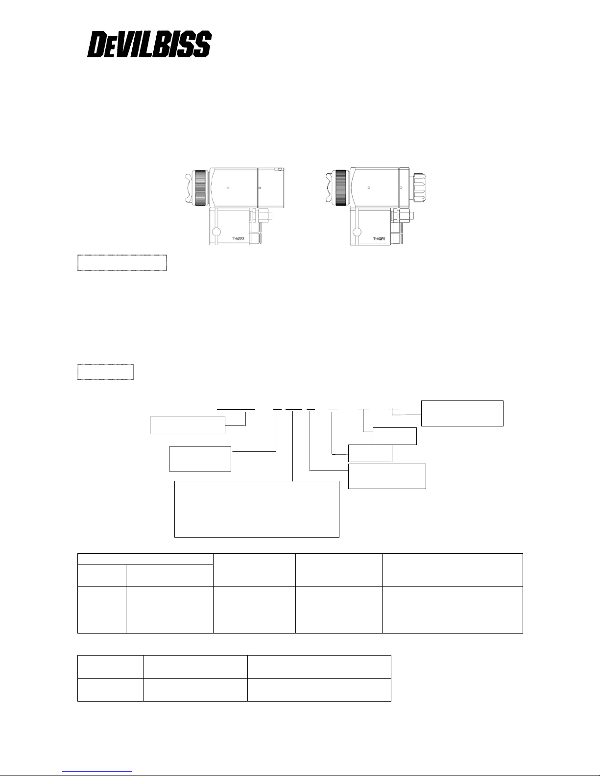
MODELS
Example:
T-AGPZ - □ □□ □- Z1 - 1.0 - TC
Chart 1
Air Cap
Fluid Tip Size
(mm)
Pattern Size Material of Fluid Tip and Needle
Marking Part Number
Z1 T-AGPZ-3-Z1 1.0 80mm Tungsten Carbide
Chart 2
Air Cap
Tip Marking (mm)
Part Number
(Tip, Needle & P ist on Set)
Z1 1.0TC T-AGPZ-440-1.0-TC
Specify only when ordering fully automatic
model 15:1.5m/m triggering
20:2.0m/m triggering
25:2.5m/m triggering (option)
(Ref: Part item no. 15- rear piston)
Basic Part Number
F: Full-Auto
S:Semi-Auto
8: Non-Circulation
9: Circulation
Air Cap
Tip Size
Tungsten Carbide
Fluid Tip and Needle
Page 2
- 2 -
SAFETY PRECAUTIONS
This manual contains important information that ALL users should know and understand BEFORE using
this equipment. This information relates to USER SAFETY and PREVENTING EQUIPMENT PROBLEMS.
To help you recognize this information, we use the following terms to draw your attention to certain
equipment labels and portions of this manual. Pay special attention to any label or information that is
highlighted by one of these terms:
WARNING
Important information to alert you to a situation that might cause serious injury or loss
of life if instructions are not followed.
CAUTION
Important information that tells how to prevent damage to equipment.
NOTE
Information that you should pay special attention to.
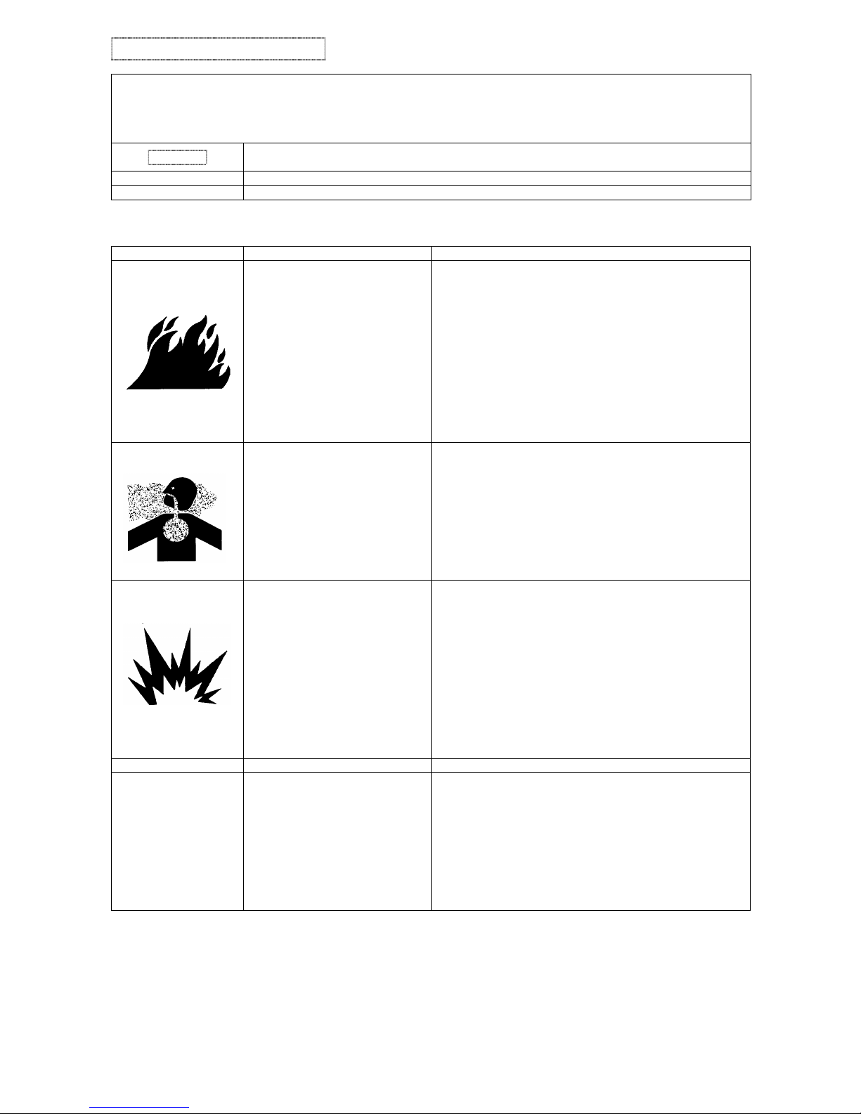
WARNING
The following hazards may occur during the normal use of this equipment. Please read the following chart.
HAZARD
CAUSE
SAFEGUARDS
Fire
Solvents and coatings can be
highly flammable or
combustible,
especially when sprayed.
1. Adequate exhaust must be provided to keep the air
free of accumulations of flammable vapors.
2. Smoking must never be allowed in spray area.
3.
Fire extinguishing equipment must be present in the
spray area.
4. Static discharges must be prevented. Ground (earth)
all conductive objects in the spray area, such as a
cleaning solvent bucket, fire extinguisher, etc.
5. When using solvents for cleaning;
・
Those used for equipment flushing must have a flash
point equal to or greater than that of the coating.
・ Those used
for general cleaning must have flash
points above 100°F(37.8℃).
Inhaling Toxic
Substances
Certain materials may be
harmful if inhaled, or if there
is contact with the skin.
1. Follow the requirements of the Material Safety Data
Sheet supplied by coating material manufa ctur er.
2.
Adequate exhaust must be provided to keep the air
free of accumulations of toxic materials.
3.
Use a mask or respirator whenever there is a chance
of inhaling sprayed materials. The mask must be
compatible with the material being sprayed
and its
concentration. Equipment must be as prescribed by
an industrial hygienist or safety expert, and be NIOSH
approved.
Explosion Hazard-
Incompatible
Materials.
Halogenated hydrocarbon
Solvents- for example:
methylene chloride and 1,1,1,
-Trichloroethane are not
chemically compatible w ith
the aluminum that might be
used in many system
components. The chemical
reaction caused by these
solvents reacting with
aluminum can become violent
and lead to an equipment
explosion.
The T -AGPZ spray gun can not be used with these
solvents.
Aluminum is widely used in other spray
application equipment – such as material pumps,
cups, regulators, valves, etc.
Check all other equipment items before use of these
solvents. Read the label or data sheet for the
material you intend to spray. If in doubt as to where
or not a coating or cleaning material is compatible,
contact your material supplier.
HAZARD
CAUSE
SAFEGUARDS
General Safety
Improper operation or
maintenance may create a
hazard.
Operators should be given adequate training in the
safe use and maintenance of the equipment (in
accordance with the requirements of NFPA-33,
Chapter 15 in U.S.). Users must comply with all
local and national codes of practice and insurance
company requirements governing
ventilation, fire precautions, operation, maintenance
and housekeeping (in the U.S., these are OSHA
Sections 1910.94 and 1910.107 and NFPA-33).
Page 3
- 3 -
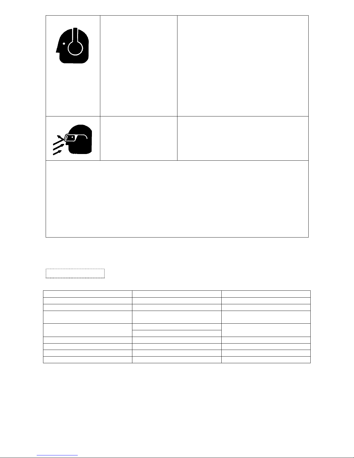
Noise Levels
The continuous A-weighted
sound pressure level of this
spray gun may exceed
85dB(A) depending on the air
cap/nozzle set-up being
used. Sound levels are
measured using an impulse
sound level meter and
analyzer, when the gun is
being used in a normal
spraying application. Details
of actual noise levels
produced by the various air
cap/nozzle set-ups are
available on request.
Wear earplugs when using the spray gun.
Spraying solvent
Pressured air/fluid passage
may be broken when
cleaning or flashing with
solvent.
The solvent may be harmful
if contacted with eyes.
Always wear eye protection when spraying or
cleaning the equipment.
MISUES:
・ All spray guns project particles at high velocity and must never be aimed t any part of body.
・ Never exceed the recommended safe working pressure for any of the equipment used.
・ The fitting of non-recommended or non-orig inal accessories or spare parts may create hazardous
conditions.
・ Before dismantling the equipment for cleaning or maintenance, all pressures, air and material, must be
isolated and released.
Disposal of non-metallic materials must be carried out in an approved manner. Burning may
generate
toxic fumes. The removal of waste solvents and coating materials should be carried out by an
authorized local waste disposal service.
SPECIFICATION
FULL-AUTO
SEMI-AUTO
Max. Air Pressure
0.7MPa (7 bar)
0.7MPa (7 bar)
Recommended Fluid Pressure
0.01MPa-0.1MPa (0.1-1 ba r )
0.01MPa-0.1MPa (0.1-1 ba r )
Recommended Atomization Air
Pressure (CAP Air)
0.1MPa – 0.3MPa (1-3 bar)
0.1MPa – 0.3MPa (1-3 bar)
Cylinder Air Pressure
Front CYL 0.25MPa
0.25 – 0.4MPa
Rear CYL 0.4MPa
Fluid Inlet
6 x 4mm
6 x 4mm
FAN / CAP Air Inlet
6 x 4mm x 2
6 x 4mm x 2
Cylinder Air Inlet
6 x 4mm x 2 (Front & Rear)
6 x 4mm
Weight
550 g
507 g
Page 4

- 4 -
INSTALLATION
Figure 1. Dimensions
CAUTION
The air supplied to the gun should be clea n air that removed any impurities.
OPERATION
Full-Auto Type (F)
1. Mix, prepare and strain the coating material to be sprayed according to paint manufacturer’s
instructions.
2. Adjust the Front CYL air at 0.25MPa and Rear CYL air at 0.4MPa.
3. Adjust CAP/FAN air at 0.1MPa - 0.15MPa.
4. Set the Fluid Delivery Level, for example, at 50 – 60cc/min by the fluid regulator HGB-510-R4 (option).
5. Turn on CYL air and test spray. Adjust fluid and air pressure until desired pattern is obtained.
Control fluid delivery at source supply. Always attempt to keep CAP air as low as possible to minimize
overspray.
Semi-Auto Type (S)
1. Mix, prepare and strain the coating material to be sprayed according to paint manufacturer’s
instructions.
2. Choose the triggering length between 1.5mm or 2.0mm and set it by turning the dial while pressing
inward on it.
3. Adjust the CYL air at 0.25MPa - 0.4MPa.
4. Adjust CAP/FAN air at 0.1MPa - 0.15MPa.
5. Set the Fluid Delivery Level, for example, at 50 – 60cc/min by the fluid regulator HGB-510-R4 (option).
6. Turn on CYL air and test spray. Adjust fluid and air pressure until desired pattern is obtained.
Control fluid delivery at source supply. Always attempt to keep CAP air as low as possible to minimize
overspray.
WARNING
Risk of injury. Equipment and fluid may be unde r pressure. Pressure in the system must be
relieved before beginning the cleaning procedure and before replacing any parts. Follow the
procedures in the literature provided with the system.
Page 5

- 5 -
CLEANING
1. When you clean the Full-Auto type gun, Rear CYL air should be stopped. In case of Semi-Auto t ype
gun, you should set the dial to “CLEAN” position.
2. Relieve air pressure from pressure tank. Carefully follow instructions in bulletin sent with tank.
3. Replace material in container with a suitable solvent.
4. Re-pressurize system.
5. Trigger gun (Front CYL air / ON at FULL-AUTO) and repeat procedure until gun and hose are thoroughly
Clean. A SolventSaver™ type hose and gun cleaner which supplies a mixture of air and solvent can be
used to most effectively clean gun and hose internal passages.
See “Accessories” for SolventSaver™. Wipe exterior of gun with a solvent dampened cloth.
6. If a recirculating system is used, it may be necessary to fit a shut off valve in return line to ensure fluid tip
and forward portion of sprayhead passage are properly cleaned when flushed with solvent.
CAUTION
Do not totally submerge gun in solvent. It may damage the inside of the gun with solids.
CAUTION
The air cap can be immersed in solvent for cleaning. If orifices are clogged, use a cocktail stick
or toothpick to remove obstruction. Never use a steel wire or hard instrument. This will damage
air cap and result in a destroyed spray pattern.
REPLACEMENT
Tools required:
• Special tool for adjusting needle seal kit (for Item No. 5)
• 19mm Box Wrench (for Item No. 4)
• 2.5mm Hex Wrench (for Item No. 30)
• 4mm Hex Wrench (for Item No. 17, 19)
• 6mm Hex Wrench (for Item No. 31)
☆ Replacing Tip, Needle & Piston Set (4)
1. Relieve all air and fluid pressure in system.
2. It is recommended to remove the Gun from the Manifold (24) by removing Bolt (31) before carrying out
any maintenance.
3. First, remove rear body (13 or 18) with 4mm Hex Wrench, then remove Needle Spring (12). Pull
Needle Assy from Gun body. When pulling out the needle ass y., use the bolt Hex (17 or 19) which
could screw into the rear side of piston.
4. Remove Retaining Ring (1) and Air Cap (3).
5. Remove Fluid Tip with 19mm Box Wrench.
6. Reassemble in reverse order.
*Recommended torque for Fluid Tip:12N・m / for M5 Bolt (17, 19, 30): 2.5N・m
* Apply petroleum jelly on cylinder of gun body and MiniY-Packing (11) and insert into gun.
* Apply petroleum jelly (Vaseline) on the rear cylinder, piston and O-Ring (16).
CAUTION
*Please ensure that t here is no foreign matter at the tip and the area where the tip will be set at the
gun body.
*It is recommended that Tip, Needle & Piston Set (4) and Needle Seal K it ( 5) MiniY-Packing(11) should
be replaced at the same time.
*Tip, Needle & Piston Set (4) is a precision machining part set. Therefore, they should be handled
with care and do not push and rotate the needle to the tip by hand after the tip has been set to the
gun body. It may damage the tungsten part of tip and needle.
☆ Replacing Needle Seal Kit (5)
1. Please follow the procedure of above replacing Tip, Neeld & Piston Set (4) until #3.
2. Remove the Needle Seal Kit from the gun body by using special tool for adjusting needle packing
T-AGPZ-34 (33 / optional accessory).
3. Set the Needle Seal Kit (5) to the special tool (option)
Insert and screw it to the gun body until it stops.
A slightly tighten it after it stops. Then the setting is completed.
The special tool is also used for checking the tightness of needle seal. If the needle movement is not
smooth enough, then seal needs to be adjusted (loosen a little).
CAUTION
*It is recommended t o use T-AGPZ-34 (33) the special tool for adjusting needle packing when you
Page 6

- 6 -
need to change the needle seal kit. The stem part of the tool is used for checking and adjusting the
tightness of sealing. (If it is too tight, the need le can’t move smoothly.)
*At the initial setting it has been set with the torque of 0.5N・m. After you reassemble all the
parts and using the Cylinder Air at 0.2MPa, if the needle does not move smoothly, need to
readjust the needle seal.
*Recommended Front Cylinder Air Pressure is 0.25MPa and Rear Cylinder Air Pressure is 0.4MPa.
*It is recommended to purchase T-AGPZ-34 (3 3) special tool, since the general tools in th e market
may not be easy to use for inserting the needle seal and adjusting the tightness.
Page 7

- 7 -
Figure 5. Gun Exploded View
Page 8

- 8 -
Item
No.
Part Number Description Q’ty Reference
1 T-AGPZ-6 Retaining Ring (with seat) 1
2 JJ-50-K5 Seat Kit of 5 1
3 Refer to Chart 1 Air Cap 1
4 Refer to Chart 2 Tip, Needle & Piston Set 1
5 T-AGPZ-10-1 Needle Seal Kit 1 Item no. 6,7,8,9,10
6 T-AGPZ-11-4-K5 Front Seal Kit of 5 1
7 T-AGPZ-190-K5 O-Ring (S9) Kit of 5 2 Perfluoro
8 T-AGPZ-12 Omni-Seal (P4) 2
9 T-AGPZ-11-3-K5 Seal Stopper Kit of 5 1
10 T-AGPZ-15-K5 Seal Stopper Clip Kit of 5 1
11 MY-18FX Mini Y-Packing 1
12 T-AGPZ-106 Needle Spring 1
13 T-AGPZ-60-20 Rear Body (2.0mm Triggering) 1
T-AGPZ-60-15 Rear Body (1.5mm Triggering) 1
14 T-AGPZ-115 Cover Ring 1
15 T-AGPZ-116-20 Rear Piston (2.0mm Triggering) 1
T-AGPZ-116-15 Rear Piston (1.5mm Triggering) 1
T-AGPZ-116-25 Rear Piston (2.5mm Triggering) 1 Option
16 T-AGPZ-P20 O-Ring (P20) 1 Perfluoro
17 ------------------ Bolt with Hex hole M5xL30 2
18 T-AGPZ-50 Rear Body (Semi-Auto) 1
19 ------------------ Bolt with Hex hole M5xL15 2
20 T-AGPZ-70
Manual Needle Position
Adjustable Kit
1 Option
21 T-AGPZ-117 Lock Nut 1
22 DA-34 Spring D 1
23 T-AGPZ-118 Adjustin g Kno b 1
24 ------------------ Manifold 1 Not for sale
25 T-AGPZ-140-K5 O-Ring (S4) Kit of 5 2 Perfuloro
26 T-AGPZ-130-K10 O-Ring (S3) Kit of 10 6 Perfuloro / 4 for Semi-Auto
27 EF7014-1-1 Fluid Connector Kit with O-Ring 2 1 for Non-Circulating
28 T-AGPV-131-K5 O-Ring (P5) Kit of 5 2
29 EC-6-R1/8A-M-R1001 Air Connector 4 3 for Semi-Auto
30 ------------------ Set Screw M5xL8 2
31 ------------------ SS Bolt with Hex Hole M8xL35 1
32 KK-4995 Gun Stud 1
33 T-AGPZ-34
Special Tool for Adjusting Needle
Seal Kit
1 Option
Page 9

- 9 -
SERVICE CHECK
Normal Spray Pattern
The proper combination of fluid pressure, fan and atomization air pressure,
and fluid tip size should result in a pattern of this shape.
PROBLEM
CAUSE
CORRECTION
Will not spray.
No pressure to gun.
Piston stops moving.
Check air and material lines.
Check CYL air pressure.
Improper spray
pattern.
A. Gun not adjusted properly.
A, B Material build up on the air
cap (3)or fluid tip.
Damage on the air cap
or fluid tip
A. Re-adjust. See “Operation
Section”.
A, B Clean the air cap or fluid tip.
Replace the air cap or fluid tip
See “Preventive Maintenance”.
Note
To determine where the material build up is, rotate the air cap 180°and test
spray. If the pattern stays in the same position, the condition is caused by
material build up on the flu id tip. If the pattern changes with air cap m ovem ent,
the build up is in the air cap.
C, D. W rong material or material
too thick.
Insufficient material or
atomizing air pressure too
high.
C, D Adjust material pressure or thin
material.
Increase material or reduce
atomizing air pressure.
Jerky or fluttering
spray.
1. Insufficient material in the tank
or an obstruction in the line.
2. Gun material passage plugged.
3. Worn Needle Seal Kit (5).
4. Loose or damaged Fluid Tip.
1. Fill tank or clear obstruction.
2. Clean.
3. Replace or tighten.
4. Tighten or replace.
Air leaking from
Rear Body.
1. Damaged or worn
MiniY-Packing (11).
2. Damaged cylinder of Gun Body.
1. Replace.
2. Replace.
Dripping from Fluid
Tip.
1. Clogged by foreign matter
2.
Worn or damaged Fluid Tip
or Needle
3.
Needle Spring damaged or
deformed.
1. Clean
2. Replace.
3. Replace.
Air or fluid leaking
from 3 holes (2mm ) of
Gun Body (5).
Damaged or worn Needle Seal Kit
(5)
Replace.
ACCESSORIES
Part Number
Description
SSL-10
Gun Lube
42884-214-K5
Cleaning Brush Kit of 5
GC-100-K48
Gun Cover Kit of 48
HD-505
Quick Cleaner (5L)
83GZ-5200
Solvent Saver (10L)
 Loading...