

Page 1
Air Cap
Marking
Part Number
G(0.7)
E(1.8)
G(0.7)
E(1.8)
Basic Part Number
Fluid Tip(Size)
E :1.8mm
Air Cap No.
807MT2
Delivery adjustable
B:Fixed type
Body material
7:Stainless steel
Paint passage
9:Circulation
T2AGPV LVMP
COMPACT AUTO GUN Operation Manual
Important:Read and follow all instructions and SAFETY PRECAUTIONS before using this equipment.
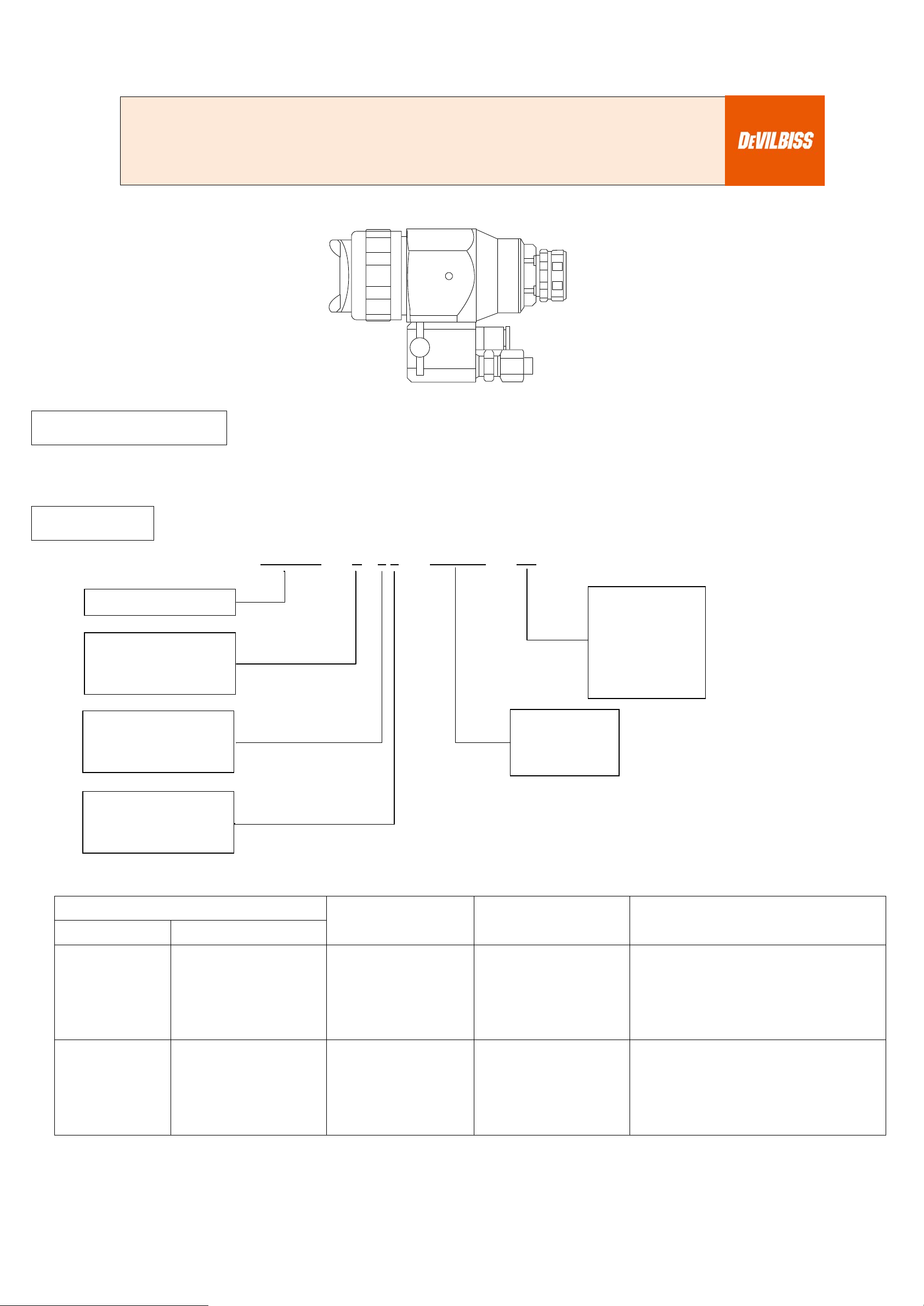
DESCRIPTION
T2AGPV LVMP gun is a small, light-weight Automatic Compact gun and suitable for robots and automatic machines.
Models and application information follows.
MODELS
Example: T2AGPV - A 7 8 - 805MT2 - FX
G :0.7mm
FX :1.1mm
A:Adjustable type
6:Aluminum
805MT2
FF :1.4mm
FW :1.6mm
8:Non-Circulation
Chart 1
805MT2 AV-1239-805MT2
807MT2 AV-1239-807MT2
Fluid Tip Size (mm) Pattern Size Shape Typical Applications
FX(1.1)
FF(1.4)
FW(1.6)
FX(1.1)
FF(1.4)
FW(1.6)
220mm Blunt
280mm Taper
Most conventional materials
Waterborne
Most conventional materials
Waterborne
1
Page 2

Chart 2
G(0.7)
T2AG-440-G
FX(1.1)
T2AG-440-FX
FF(1.4)
T2AG-440-FF
E(1.8)
T2AG-440-E
FF(1.6)
Fluid Tip
Needle
T2AG-4S-G
T2AG-4S-FW
T2AG-402-FZ
T2AG-402-FZ
805MT2
807MT2
Air Cap Tip Marking (mm) Part Number (Tip & Needle Lapped Set)
805MT2
807MT2
G(0.7)
FX(1.1)
FF(1.4)
T2AG-4S-FX
T2AG-4S-FF
T2AG-402-FZ
T2AG-402-FZ
2
Page 3
SAFETY PRECAUTIONS
Important information to alert you to a situation that might cause serious injury or loss of life if instructions
are not followed.
CAUTION
Important information that tells how to prevent damage to equipment.
NOTE
Information that you should pay special attention to.
HAZARD
CAUSE
SAFEGUARDS
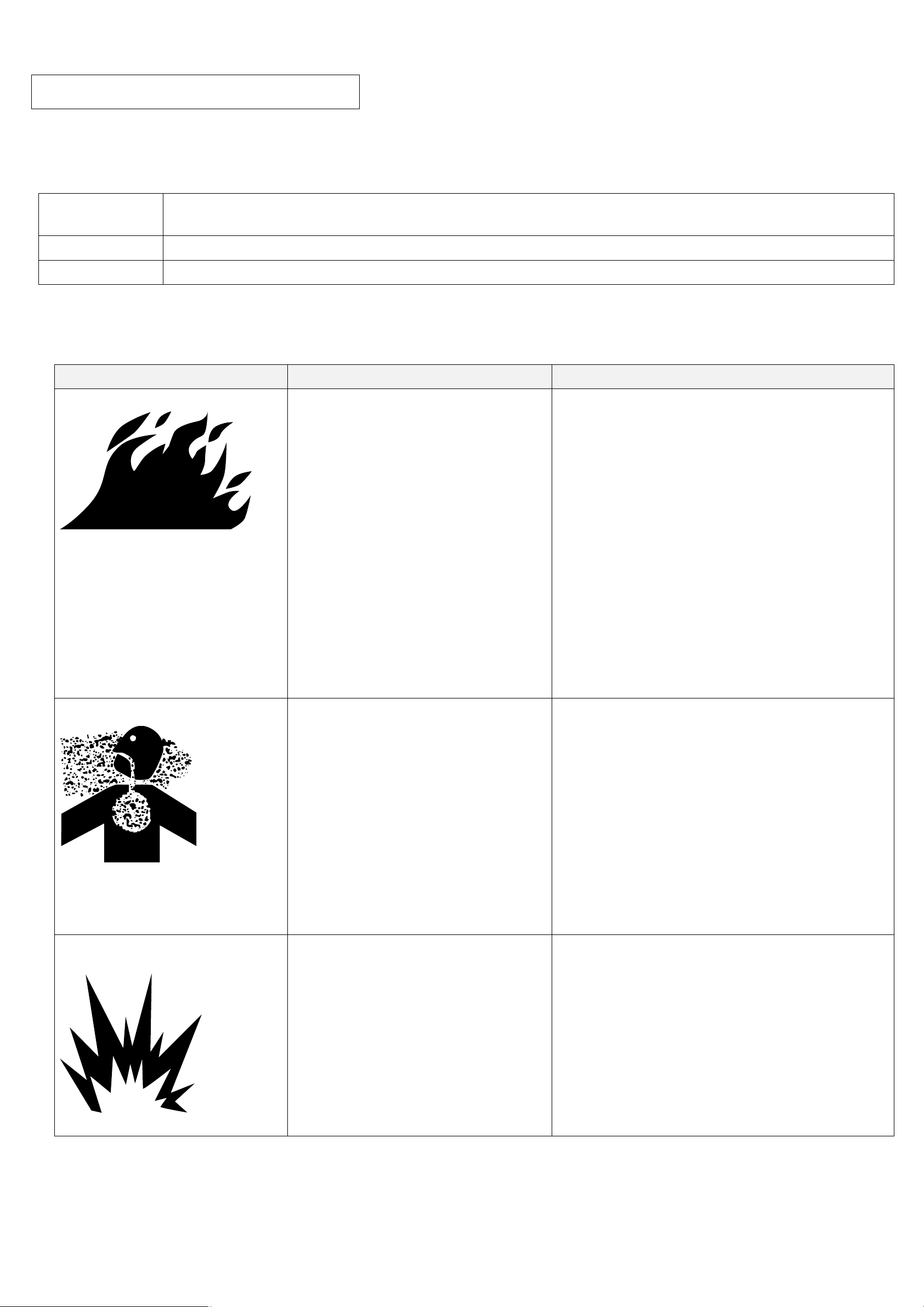
Fire
Solvents and coatings can be highly
1. Adequate exhaust must be provided to keep
have flash points above 100°F (37.8°C).
Inhaling Toxic Substances
Certain materials may be harmful if
1. Follow the requirements of the Material
NIOSH approved.
Explosion Hazard –
Halogenated hydrocarbon Solvents-
equipment explosion.
The T-AGB spray gun can be used with these
This manual contains important information that ALL users should know and understand BEFORE using this equipment. This
information relates to USER SAFETY and PREVENTING EQUIPMENT PROBLEMS.
To help you recognize this information, we use the following terms to draw your attention to certain equipment labels and
portions of this manual. Pay special attention to any label or information that is highlighted by one of these terms:
WARNING
WARNING
The following hazards may occur during the normal use of this equipment. Please read the following chart.
flammable or combustible, especially
when sprayed.
the air free of accumulations of flammable
vapors.
2. Smoking must never be allowed in the spray
area.
3. Fire extinguishing equipment must be
present in the spray area.
4. Static discharges must be prevented.
Ground(earth) all conductive objects in the
spray area, such as a cleaning solvent
bucket, fire extinguisher, etc.
5. When using solvents for cleaning:
• Those used for equipment flushing must
have a flash point equal to or greater than
that of the coating.
•
Those used for general cleaning must
inhaled or if there is contact with the
skin.
Safety Data Sheet supplied by coating
material manufacturer.
2. Adequate exhaust must be provided to keep
the air free of accumulations of toxic
materials.
3. Use a mask or respirator whenever there is a
chance of inhaling sprayed materials. The
mask must be compatible with the material
being sprayed and its concentration.
Equipment must be as prescribed by an
industrial hygienist or safety expert, and be
Incompatible Materials
for example:
methylene chloride and
1,1,1,-Trichloroethane are not
chemically compatible with the
aluminum that might be used in
many system components. The
chemical reaction caused by these
solvents reacting with aluminum can
become violent and lead to an
3
solvents.
However, aluminum is widely used in other
spray application equipment – such as material
pumps, cups, regulators, valves, etc. Check all
other equipment items before use of these
solvents. Read the label or data sheet for the
material you intend to spray. If in doubt as to
where or not a coating or cleaning material is
compatible, contact your material supplier.
Page 4

HAZARD
CAUSE
SAFEGUARDS
General Safety
Improper operation or maintenance
may create a hazard.
Operators should be given adequate training in
1910.107 and NFPA-33).
Noise Levels
The continuous A-weighted sound
request.
Wear earplugs when using the spray gun.
Spraying solvent
Pressured air/fluid passage may be
Always wear eye protection when spraying or
Misuse:
The removal of waste solvents and coating materials should be carried out by an authorized local waste disposal service.
pressure level of this spray gun may
exceed 85dB(A) depending on the
air cap/nozzle set-up being used.
Sound levels are measured using an
impulse sound level meter and
analyzer, when the gun is being used
in a normal spraying application.
Details of actual noise levels
produced by the various air
cap/nozzle set-ups are available on
the safe use and maintenance of the equipment
(in accordance with the requirements of
NFPA-33, Chapter 15 in U.S.). Users must
comply with all local and national codes of
practice and insurance company requirements
governing ventilation, fire precautions, operation,
maintenance and housekeeping (in the U.S.,
these are OSHA Sections 1910.94 and
broken when cleaning or flashing
with solvent.
The solvent may be harmful if
contacted with eyes.
• All spray guns project particles at high velocity and must never be aimed t any part of body.
• Never exceed the recommended safe working pressure for any of the equipment used.
• The fitting of non-recommended or non-original accessories or spare parts may create hazardous conditions.
• Before dismantling the equipment for cleaning or maintenance, all pressures, air and material, must be isolated and
released.
Disposal of non-metallic materials must be carried out in an approved manner. Burning may generate toxic fumes.
cleaning the equipment.
4
Page 5

SPECIFICATIONS
Max. Fluid Pressure
0.69MPa (7.0kgf/cm2)
Cylinder Air Pressure
Min. 0.34MPa (3.5 kgf/cm2)
Max. 0.49MPa (5.0 kgf/cm2)
Weight
Mounting Stud
Dia. 19mm x 51mm
Fluid Tube
6x4mm
Max. Air Pressure 0.69MPa (7.0kgf/cm2)
730g (SUS / Adjustable type / Type for Non-Circulation)
336g (Aluminum/Adjustable type /
CYL Air Tube 6x4mm
CAP Air Tube 6x4mm
FAN Air Tube 6x4mm
Type for Non-Circulation)
INSTALLATION
Figure 1. Dimensions
5
Page 6

Figure 2. Installation
Mount the gun with the stud (Ø19) or tighten with Manifold (14) 8.2mm whole.
CAUTION:
The air supplied to the gun should be clean air that removed any impurities.
OPERATION
1. Mix, prepare and strain the coating material to be sprayed according to paint manufacturer’s instructions.
2. Adjust the CYL air at 0.34~0.49Mpa.
3. When the adjustable type is used, turn the Adjusting Screw counter-clockwise about 4.0 turns from fully closed position to
make it fully opened (where it lightly bumps against). Do not turn it more than that.
4. Adjust the CAP/FAN air at about 0.20Mpa.
5. Adjust fluid air at about 0.07Mpa~0.1Mpa.
6. Turn on CYL air and test spray. Adjust fluid and air pressure until desired pattern is obtained. Control fluid pressure at
source supply. Always attempt to keep CAP pressure as low as possible to minimize overspray.
WARNING
Risk of injury. Equipment and fluid may be under pressure. Pressure in the system must be relieved before beginning the
cleaning procedure and before replacing any parts. Follow the procedures in the literature provided with the system.
CLEANING
1. Please follow the instruction manual for the pressure tank or the feed pump to clean the supply equipment.
2. Supply gun with thinner from that supply equipment or another supply device.
3. Turn on CYL air and clean the fluid passages until the thinner comes out clean and clear. Quick Cleaner which supplies a
mixture of air and solvent can be used to improve cleaning efficiency and save solvent. See “ACCESSORIES” for Quick
Cleaner. Wipe gun exterior with a solvent dampened cloth.
4. When the gun is used in a paint circulation system, it may be necessary to design a system in which the paint return line
will be shut off temporarily in order to clean the forward portion of the gun.
CAUTION
Do not totally submerge gun in solvent. It is possible to damage the inside of the gun with solids.
CAUTION
The air cap can be immersed in solvent for cleaning. If orifices are clogged, use a cocktail stick or toothpick to remove
obstruction. Never use a steel wire or hard instrument. This will damage air cap and result in a distorted spray pattern.
6
Page 7

REPLACEMENT
Tools Required
Crescent Wrench
10mm or 13mm Box Wrench
Pliers (for Needle Assy)
Open Wrench
Hex Wrench
Fluid Tip (5)
1. Relieve all air and fluid pressure in system.
2. Remove Rear Body (10or11), Needle Spring (9). Pull Needle Assy (8) out from gun body with Pliers.
3. Remove Retaining Ring (1) and Air Cap (4).
4. Remove Fluid Tip (5) with 1/2 Box Wrench.
5. Reassemble in reverse order. Recommended torque of Fluid Tip (5): 16~20N・m.
Replacing Needle Assy (8), Piston Seal (7)
1. Remove Rear Body (10or11), Needle Spring (9). Pull Needle Assy (8) out from gun body with Pliers.
2. Insert the new Needle Assy and install the Spring and Rear Body.
3. Piston Seal should not be reused because it would be damaged when removed.
Replacing Needle Seal Kit (6)
1. Remove Rear Body (10or11), Needle Spring (9). Pull Needle Assy (8) out from gun body with Pliers.
2. Remove Needle Seal Kit (6) with 13mm Box Wrench or specialized tool (Optional).
3. Attach new Needle Seal Kit (6) to the gun body with the 13mm Box Wrench or specialized tool (Optional). Before doing it
please apply a little bit of vaseline to the O-ring of the Seal Kit.
4. Before inserting to the gun, apply vaseline to the Piston Seal (7) of Needle Assay (8).
5. Insert Needle Spring (9), and assemble Rear Body.
6. Pressure 0.35Mpa on CYL and check the movement of needle.
Figure 5. Gun Exploded View
7
Page 8

Item No.
Part Number
Description
Q’ty
Remarks
1
T2AG-368
Retaining Ring
1
with Cap Seat and Ring Gasket
2
T2AG-50-K5
Cap Seat
1
5 pieces
3
T2AG-55-K5
Ring Gasket
1
5 pieces
4
Refer to Chart1
Air Cap
1
5
Refer to Chart2
Fluid Tip
1
6
T2AG-10
Needle Seal Kit
1
7 T2AG-102
Piston Seal
1
8 Refer to Chart2
Needle
1
9
T2AG-106
Needle Spring
1
10
T2AG-500
Rear Body(Fixed type)
1
11
12
T2AG-140
O-Ring (Small) S4
3
2 for fluid, 1for air
13
T2AG-130
O-Ring (Big) S6
2
for air
14
T2AG-100AL
T2AG-100SS
Manifold (Aluminum)
Manifold (SUS)
1
15
--------
Hexagon Socket Bolt M6×L25
1
Commercial product
16
--------
Plug 1/8
1
Commercial product
17
T2AG-STU-64
Joint for Fluid
2
with Fluid Seal
18
EC6-R1/8A-M-R1001
Joint for Air
3
19
T2AG-TU-1-K5
Fluid Seal Kit of 5
2
T2AG-3-K
Mounting Stud Kit
Optional
T-AGPZ-34
Specialized Tool for Needle Seal Kit
Optional (Refer to Figure 5.)
T2AG-700
Rear Body(Adjustable type with scale)
Optional (Refer to Figure 5.)
T2AG-600 Rear Body(Adjustable type) 1
8
Page 9

SERVICE CHECK
Will not spray.
No pressure to gun.
Piston stops moving.
Check air and material lines.
Check CYL air pressure.
Improper spray pattern.
A. Gun not adjusted properly.
A. Re-adjust. See “Operation Section”.
Note
spray. If the pattern
. If the
pattern changes with air cap movement, the buildup is in the air cap (4).
C, D. Wrong material or material too thick.
pressure too high.
C, D Adjust material pressure or thin material.
air pressure.
Jerky or fluttering spray
1. Insufficient material in the tank or an obstruction
1. Fill tank or clear obstruction.
Air leaking from the
Damaged or worn Piston Seal (7).
Replace.
be used depending on the
extent of the damage.
Liquid spill from Fluid Tip
Clogged Needle (8) of the Fluid Tip (5)
Damaged or deformed Needle Spring (9)
Clean.
Replace.
Air or paint leaking from
body
Damaged or worn Needle Seal Kit (6)
Replace.
SSL-10
Gun Lube (60cc)
42884-214-K5
Cleaning Brush Kit of 5
Quick Cleaner(5)
HD-510
Quick Cleaner(10)
KK-5033-805MT
Air Cap Test Gauge (for AV1239-805MT2)
KK-5033-807MT
Air Cap Test Gauge (for AV1239-807MT2)
AGA-415
Universal Clamp
Normal spray pattern
©2017 Carlisle Fluid Technologies.
HP http://www.carlisleft.co.jp
DIVISION
®DEVILBISS is a registered trademark of Carlisle Fluid Technologies.
®Jupiter is a registered trademark of CFT Ransburg Japan KK.
Ransburg Japan KK
The proper combination of fluid pressure, fan and atomization air pressure,
Problem Cause Correction
and fluid tip size should result in a pattern of this shape.
A, B. Material build up on the air cap (4)or fluid
tip (5).
To determine where the material build up is, rotate the air cap (4) 180°and test
stays in the same position, the condition is caused by material build up on the fluid tip (5)
Insufficient material or atomizing air
in the line.
2. Gun material passage plugged.
3. Worn Needle Seal Kit (7).
4. Loose or damaged Fluid Tip (3).
A, B. Clean the air cap or fluid tip. See
“Preventive Maintenance”.
Increase material or reduce atomizing
2. Clean.
3. Replace or tighten.
4. Tighten or replace.
center hole of Rear Body
(5)
the 3mm hole of the gun
Damaged cylinder part of the gun body
Damaged or worn Fluid tip (5) or Needle (8)
ACCESSORIES
Part No. Description
GC-100-K48 Gun Cover Kit of (48)
Gun body may not
Replace.
HD-505-W
9
2017-08-
T2AGPV LVMP
 Loading...