

Page 1
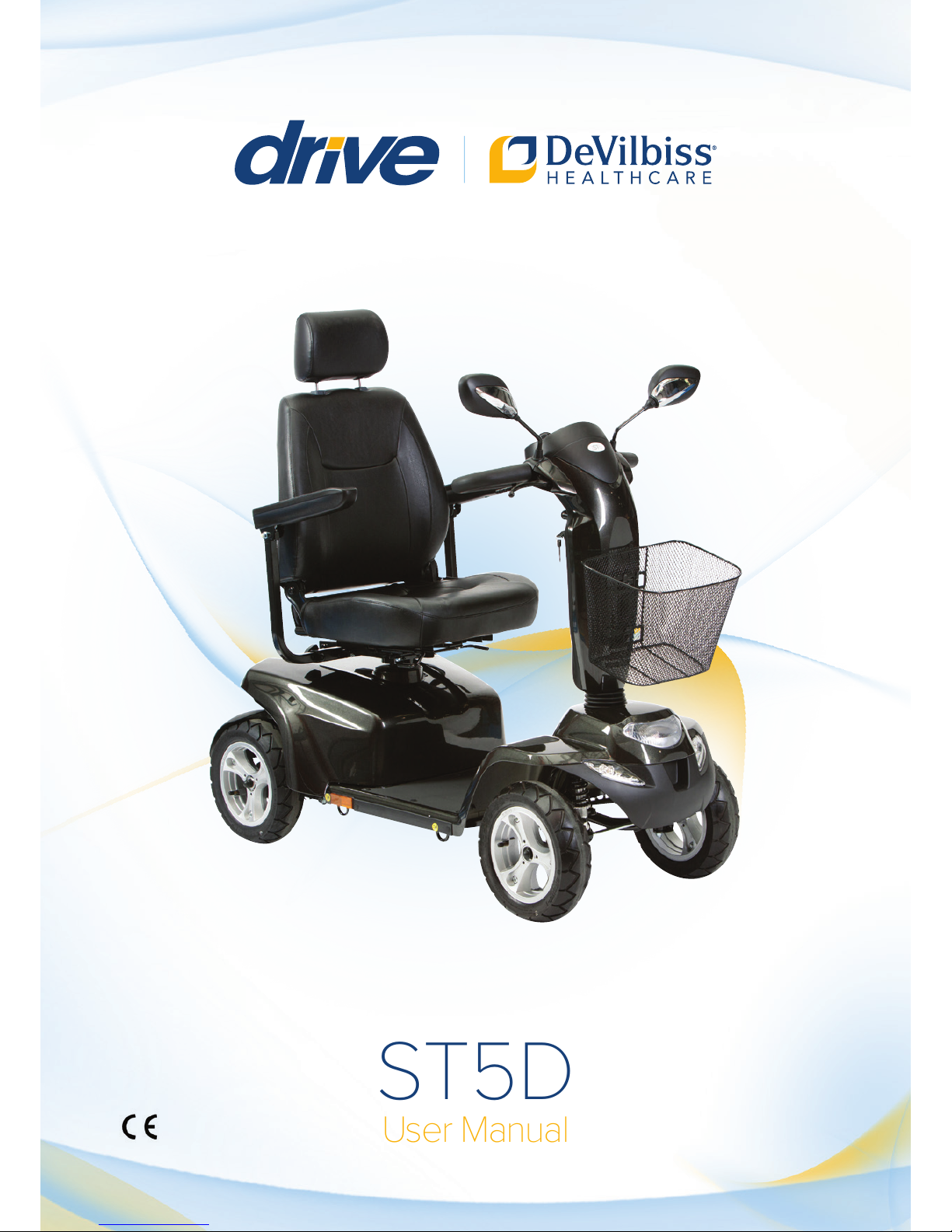
ST5D
User Manual
Page 2

ST#5
Instruction Booklet
TABLE OF CONTENTS
INTRODUCTION
--------------------------------------------------------- 1
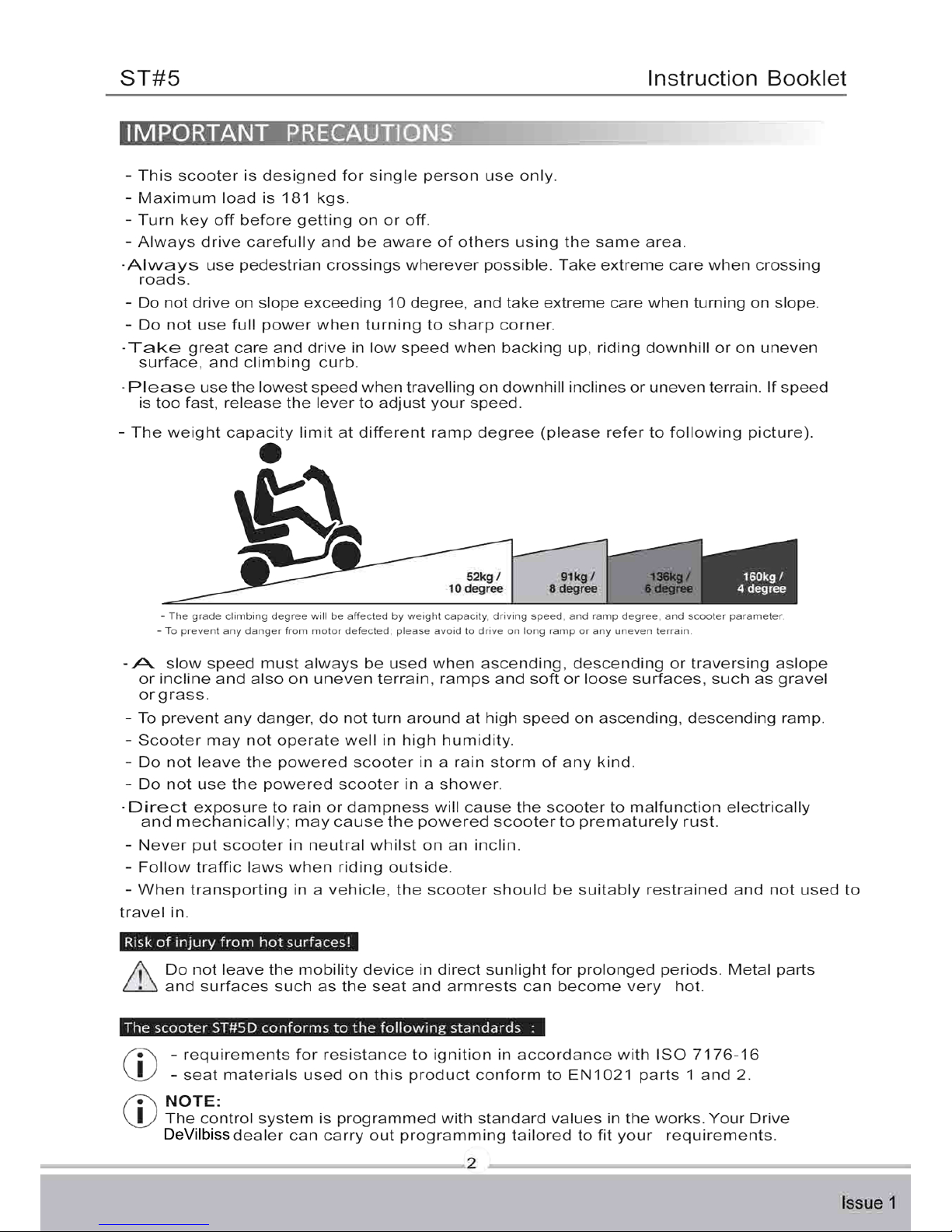
IMPORTANT PRECAUTIONS
----------------------------------------- 2
ELECTROMAGNETIC INTERFERENCE AND WARNINGS
----- 3
IDENTIFICATION OF PARTS
CHARGING THE BATTERIES
----------------------------------------5
-
-------------------------------------11
DISASSEMBLING YOUR SCOOTER
-------------------------------- 12
ASSEMBLING Y
OUR SCOOTER
-------------------------------------- 13
CARE AND MAINTENANCE
------------------------------------------ 14
OPERATING YOUR SCOOTER
------------------------------------ 15
TROUBLESHOOTING
------------------------------------------------- 17
TECHNICAL
SPECIFICATIONS
---------------------------------------- 19
INSPECTION CHECKS
---------------------------------------------- 20
Page 3
ST#5
Instruction Booklet
1
Issue 1
Thank you and congratulations on purchasing your new Drive DeVilbiss mobility
scooter. It is designed to provide you with transportation ability indoors and outdoors.
We pride ourselves on providing safe and comfortable products. Our goal is to ensure
your complete satisfaction. We sincerely hope you enjoy your new Mobility Scooter.
Important symbols in this manual & Product Markings
General risks
This symbol warns you of general hazards!
Always follow the instructions to avoid injury to the user or damage to the product.
READ THIS MANUAL FULLY BEFORE OPERATION!
This symbol advises you to read information carefully.
This symbol identifies general information
which is intended to simplify working
with your product and which refers to special functions.
Please read and observe all warning and instruction provided in owner's manual
before you operate the various functions of this scooter. Also, please
retain this booklet for future reference.
The vehicle has been successfully safety-tested to German and international standards.
It was also successfully tested to EN60529 IPX4 for splash water insensitivity, and is
therefore ideally suitable for typical central European weather conditions.
If you are visually impaired, this document can be viewed in PDF format at
www.drivedevilbiss.co.uk or alternatively is available on request in large text.
Life expectancy
We estimate a life expectancy of five years for this product, provided it is used in
strict accordance with the intended use as set out in this document and all maintenance
and service requirements are met. The estimated life expectancy can be exceeded if
the product is carefully used and properly maintained, and provided technical and
scientific advances do not result in technical limitations. The life expectancy can also
be considerably reduc
ed by extreme or incorrect usage.
The fact that we estimate a life expectancy for this product does not constitute an
additional warranty.
If you have any question, you can contact :
Information of European Representative :
EMERGO EUROPE
Molenstraat 15
2513 BH, The Hague
The Netherlands
or your local dealer:
Page 4
DeVilbiss
Page 5
ST#5
Instruction Booklet
3
Issue 1
CAUTION: It is very important that you read this information regarding the possible
effects of Electromagnetic Interference on your motorized scooter.
Powered wheelchairs and motorized scooters may be susceptible to electromagnetic
interference (EMI), which is interfering electromagnetic energy (EM) emitted from sources
such a radio stations, TV stations, amateur radio (HAM) transmitters, two-way radios, and
cellular phones. The interference (from radio wave sources) can cause the motorized
scooter to release its brakes, move by itself, or move in unintended directions. It can also
permanently damage the motorized scooter control system. The intensity of the interfering
EM energy can be measured in volts per meter (V/m). Each motorized scooter can resist
EMI up to a certain intensity. This is called its "immunity level." The higher the immunity
level, the greater the protection. At this time, current technology is capable of achieving at
least a 20 V/m immunity level, which would provide useful protection from the more
common sources of radiated EMI. The immunity level of this motorized scooter model is not
known.
There are a number of sources of relatively intense electromagnetic fields in the everyday
environment. Some of these sources are obvious and easy to avoid. Others are not
apparent and exposure is unavoidable. However, we believe that by following the warnings
listed below, your risk to EMI will be minimized.
The sources of radiated EMI can be broadly classified into three types :
1. Hand-held portable transceivers (transmitters-receivers) with the antenna mounted
directly on the transmitting unit. Examples include: citizens band (CB) radios, "walkie
talkie," security, fire, and police transceivers, cellular telephones, and other personal
communication devices
2. Medium-range mobile transceivers, such as those used in police cars, fire trucks,
ambulances, and taxis. These usually have the antenna mounted on the outside of the
vehicle; and
3. Long-range transmitters and transceivers such as commercial broadcast transmitters
(radio and TV broadcast antenna towers) and amateur (HAM) radios
Page 6

ST#5
Instruction Booklet
4
Issue 1
Motorized Scooter Electromagnetic Interference:
Because EM energy rapidly becomes more intense as one moves closer to the transmitting
antenna (source), the EM fields from hand-held radio wave sources (transceivers) are of
special concern. It is possible to unintentionally bring high levels of EM energy very close to
the motorized scooter control system while using these devices. This can affect motorized
scooter movement and braking. Therefore, the warnings listed below are recommended
to prevent possible interference with the control system of the motorized scooter.
Safety information on electromagnetic interference
This electric vehicle was successfully tested in accordance with International standards
as to its compliance with Electromagnetic Interference (EMI) regulations. However,
electromagnetic fields, such as those generated by radio and television transmitters, and
cellular phones can influence the functions of electric vehicles. Also, the electronics used in
our vehicles can generate a low level of electromagnetic interference, which however will
remain within the tolerance permitted by law. For these reasons we ask you to please
observe the following precautions:
Warnings:
Danger of malfunction due to electromagnetic interference!
‧
Do not switch on or operate portable transceivers or communication devices (such as
radio transceivers or cellular phones) when the vehicle is switched on.
‧
Avoid getting near strong radio and television transmitters.
‧
In case the vehicle should be set in motion unintentionally or the brakes are released,
switch it off immediately.
‧
Adding electrical accessories and other components or modifying the vehicle in any way
can make it susceptible to electromagnetic interference. Keep in mind that there is no
sure way to determine the effect such modifications will have on the overall immunity
of the electronic system.
‧
Report all occurrences of unintentional movement of the vehicle, or release of the electric
brakes to the manufacturer.
Important Information:
1.20 volts per meter (V/m) is a generally achievable and useful immunity level against
EMI (as of May 1994). The higher the level, the greater the protection.
2.The immunity level of this product is at least 20/Vm.
Page 7
ST#5
Instruction Booklet
5
Issue 1
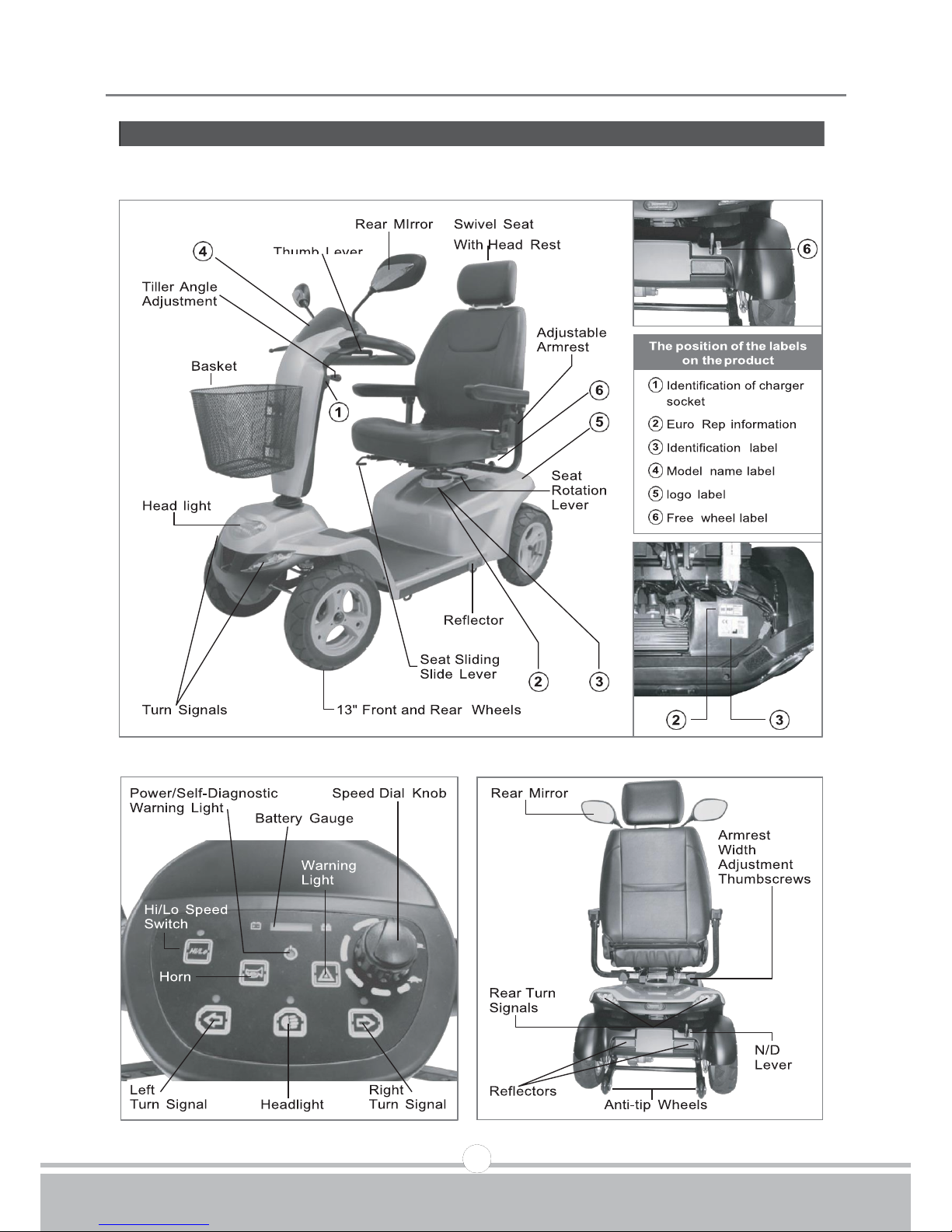
Before attempting to drive this scooter on your own, it is important that you familiarize
yourself with the controls, and how to operate
Figure 1 - ST-5 Front View
Figure 2
-
ST-5 Control Panel Figure 3 - ST-5 Rear View
Page 8

ST#5
Instruction Booklet
6
Issue 1
FUNCTION OF PARTS:
MAIN SWITCH (A)
1.
To switch on the machine turn the key clockwise to ON.
2.
To switch the machine off turn the key anti-clockwise to OFF.
Speed Dial Knob (B)
Maximum speed can be limited by setting the control to tortoise for slow or hare for fast.
Horn Button (C)
depress
Battery Gauge (D)
There is a meter shows batteries capacity status.
When battery gauge light trends to , it means sufficient power capacity.
When battery gauge light trends to , it means insufficient power capacity.
TOP CONTROL PANEL (Hi/Lo)
High & Low Speed Switch allows speed to be changed from the normal maximum 12.8 kmph
to half for pavement use.
Panel Control
Pressing down to activate left turn signal.
Pressing down to activate right turn signal.
Pressing down to activate warning light.
Pressing down to activate headlight.
Pressing down
HI/LO
to activate Hi/Lo speed.
Indicator:
1. Light means activated Hi/Lo speed.
2.Light means activated left turn signal
3.Light means activated headlight.
4.Light means activated right turn signal
Page 9
ST#5
Instruction Booklet
7
Issue 1
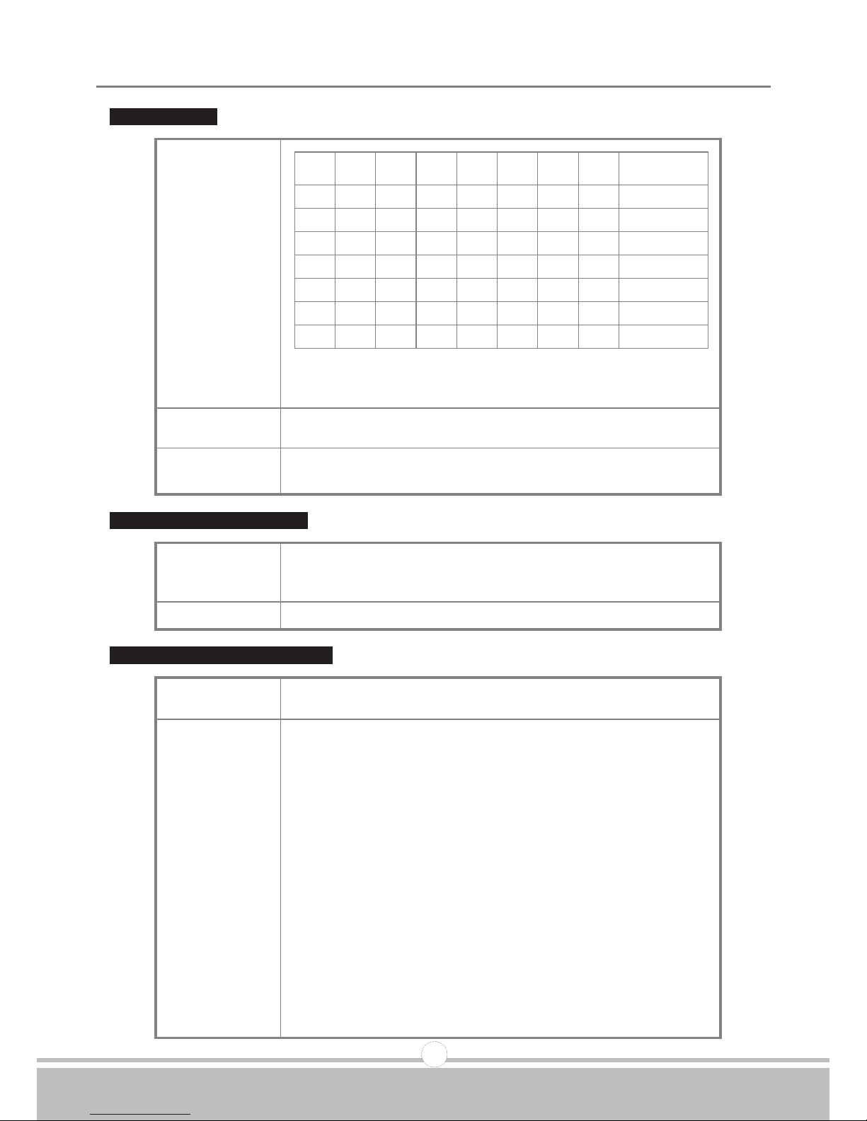
Battery Gauge
Capacity
Display
D1、D2 : Red LED
D3、D4 : Amber LED D5
、D6、
D7 : Green LED
Operation
Characteristic
LED blocks will only decrease gradually during driving.
Usage
Condition
(1)
When turn off power
(2)
When charging, function will shut off.
Low Voltage Warning Sound
Operation
Characteristic
Warning sound will signal, when battery capacity's lower
than 25%, after turn on the power, 2 short "Be" sounds
will signal 3 times (Be Be-Be Be-Be Be)
Remark
Can be set as on or off.
Warning Sound (On, Off) Setting
Operation
Characteristic
Sound of turn signal, stop, low voltage, reversing can
be set as on or off
Description of
Volume
Setting Steps
1.Ensure power is turned off
2.Pressing left and right turn signal buttons downwards
simultaneously.
3. Turn on the power.
4.After 2 seconds, LED (D7) flashes to indicate the setting
start, if hold on buttons for 10 seconds without releasing
(left and right turn signal buttons) will automatically
leave setting mode.
5.Pressing volume setting button (As Stop (Warning) light
button) to access volume setting mode, by pressing
button (Ex: Stop (Warning) light button) to adjust volume.
6.Waiting for 10 seconds without action, or pressing left
and right turn signal buttons downwards simultaneously
for 2 seconds to return to normal operation mode.
LED D1 D2 D3 D4 D5 D6 D7
Battery
Capacity%
7
☆ ☆ ☆ ☆ ☆ ☆ ☆
>80
6
☆ ☆ ☆ ☆ ☆
☆
<80 5
☆ ☆ ☆ ☆ ☆
<65
4
☆ ☆ ☆
☆
<50 3
☆ ☆ ☆
<35
2
☆
☆
<25 1
☆
<20
Page 10
ST#5
Instruction Booklet
8
Issue 1
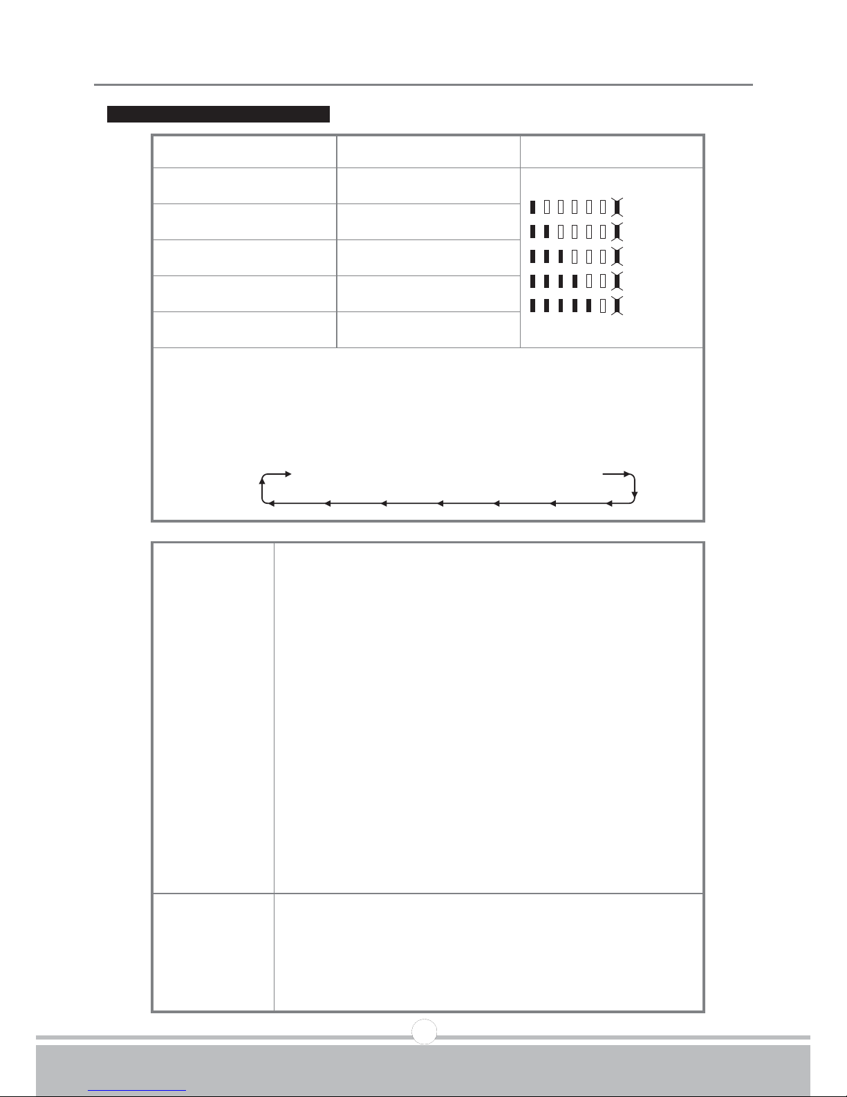
Table of Warning Sound Settings
Function
Volume Button
Volume Adjustment
Reverse Warning Sound
Head Light Button
Flash
Off
Minimum
Low
Mid
Loud
Except horn volume can
not be set as off
Turn Signal Warning
Sound
Left or Right Turn Signal
Button
Stop (Warning) Warning
Sound
Stop (Warning) Light
Button
Low Voltage Warning
Sound
Hi & Lo Button
Horn Volume
Horn Button
P.S: Pressing volume button (ex:Stop (Warning) to access volume adjustment
mode, the LED displays to volume blocks and the volume (ex:Stop
(Warning) Sound signal, press (Stop (Warning) Light button again, the
volume and LED will decrease gradually, by pressing button once will
increase or decrease one block:
Loud >> Mid >> Low >> Minimum >> Off
Examples
Reversing Warning Sound Volume Adjustment
1.Turn off the power (Key off)
2. Pressing left and right turn signal buttons downwards
simultaneously.
3.Turn on the power(Key on)
After 2 seconds, LED (D7) flashes (meaning accessed
in volume setting mode),
Release the buttons within 10 seconds (left and right
turn signal buttons).
4. Pressing Head Light button to access Reverse Warning
Sound.
5.Pressing Head Light button to adjust volume
6. After setting, waiting for 10 seconds without action, or
pressing left and right turn signal buttons downwards
simultaneously for 2 seconds to return to normal
operation mode.
Default
Turn Signal Warning Sound=Mid
Stop (Warning) Light Warning Sound=Mid
Low Voltage Warning Sound=Mid
Reversing Warning Sound=Mid
Horn Volume=Loud
Page 11
ST#5
Instruction Booklet
9
Issue 1
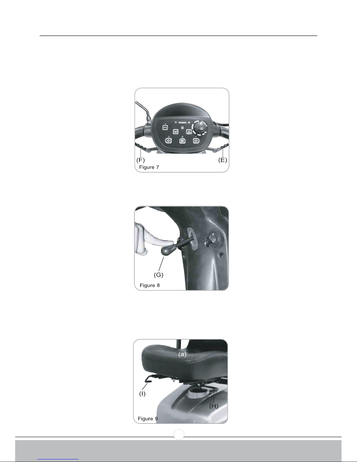
Thumb Lever
Pulling right thumb lever (E) moves scooter forward. Pulling left thumb lever (F) moves
the scooter backward. (This can be reversed if required by local dealer.) Releasing both,
engages automatic brake. These are also your accelerator. The further you depress them,
the faster you go. (Subject to the position of the Rabbit/Turtle control).
Tiller Angle Adjustment
Pulling the tiller adjustment (G) downwards to adjust tiller's angle and release to lock at
a desired comfortable position.
Seat Swivel Adjustment
Setting at a comfortable angle by pulling lever (H) upwards to rotate seat (a) left and right..
Seat fore-aft Adjustment
Setting at a comfortable position by lifting lever (l) upwards to adjust the seat (a).
Page 12
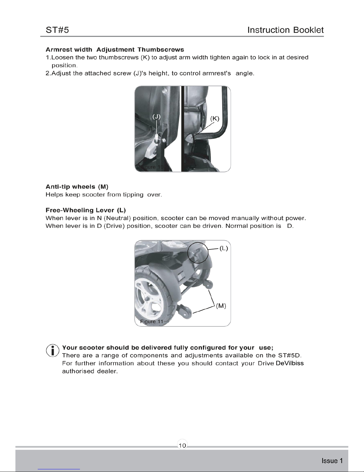
DeVilbiss
Page 13
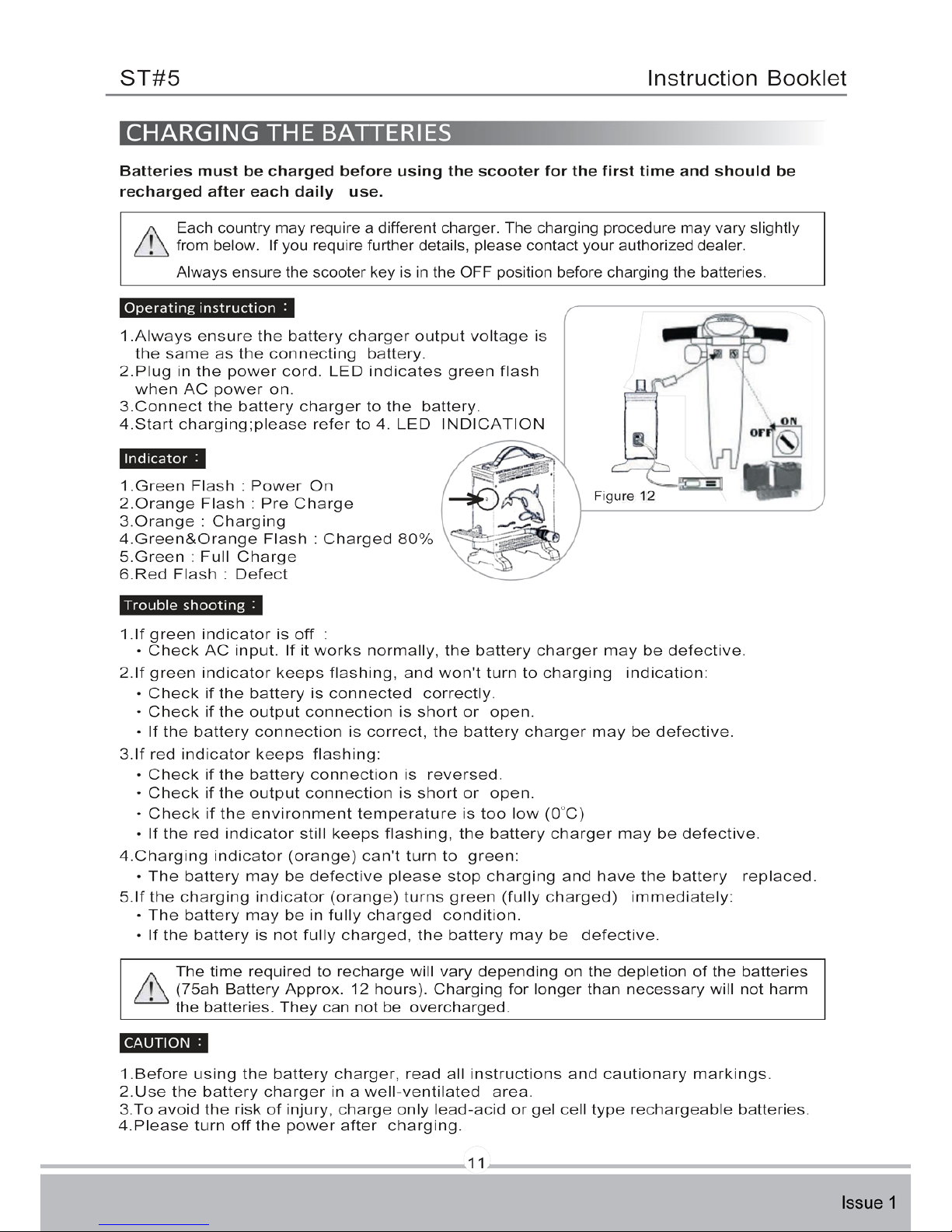
Page 14
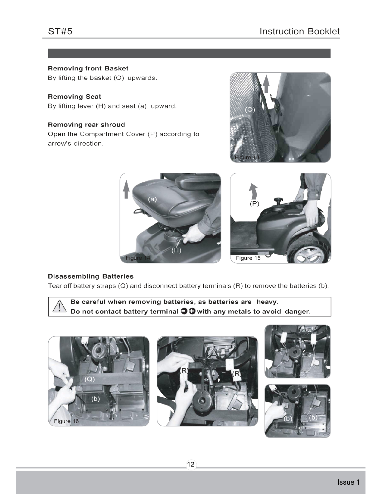
12
Page 15
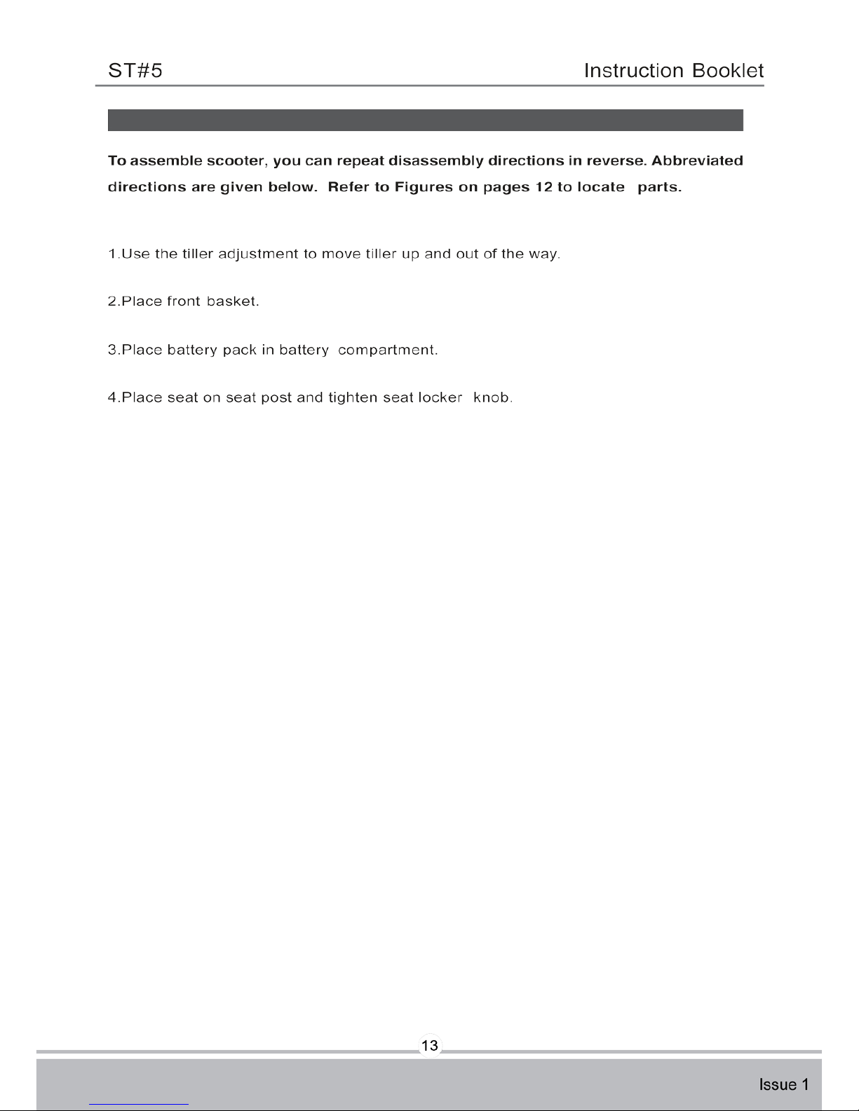
13
Page 16
DeVilbiss
DeVilbiss
14
Page 17
15
Page 18
16
Page 19
17
Page 20
18
Page 21
19
Page 22
DeVilbiss
Page 23
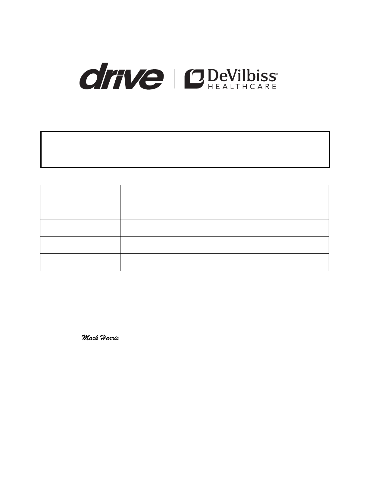
CERTIFICATE OF NEWNESS
THIS DOCUMENT SHOULD BE SUBMITTED WITH THE V55/4 FORM
TO REGISTER THE VEHICLE WITH THE DVLA.
Make Drive DeVilbiss
Type of Body Metal and Plastic
Serial Number
Weight w/Batteries 138 kg / 304 Ibs
Top Speed 12.8 kmph / 8 mph
I declare that the mobility scooter described above is new and
unused, and has not been registered before.
Signed:
On behalf of Drive DeVilbiss
Date:
Drive DeVilbiss Healthcare Ltd.
Heathfield Lane, Birkenshaw,
West Yorkshire, BD11 2HW
Page 24
Dealer Stamp
Drive DeVilbiss Healthcare Ltd, Heathfield Lane,
Birkenshaw, West Yorkshire, BD11 2HW
Tel: 0845 0600 333
Fax: 0845 0600 334
Email: info@drivedevilbiss.co.uk
www.drivedevilbiss.co.uk
Warranty Information
Drive DeVilbiss ST5D Scooters are warranted for 12months
(24 months frame) from the date of purchase on side frames
and crossbars. (NB Batteries are warranted for 12 months.)
» During the warranty period any parts that have become defective
due to faulty workmanship or material will be repaired or replaced
without charge by Drive DeVilbiss supplier/dealer
» The warranty excludes tyres, punctures and items that become worn
due to normal wear and tear such as upholstery and armrest pads
» The warranty excludes all items that have been
subject to undue wear and tear and misuse
» Unauthorised changes or modifications will forfeit your warranty
» If a defect or fault is discovered, the Drive DeVilbiss
supplier/dealer from whom the Wheelchair was purchased
should be notified immediately
Limitation of Liability
The warranty does not extend to the consequential costs resulting
from fault clearance, in particular freight and travel costs, loss of earnings,
expenses, etc. The manufacturer will not accept responsibility for any
damage or injury caused by misuse or non-observance of the
instructions set out in this user manual.
 Loading...