

Page 1
SB-E-2-510
Operation Manual
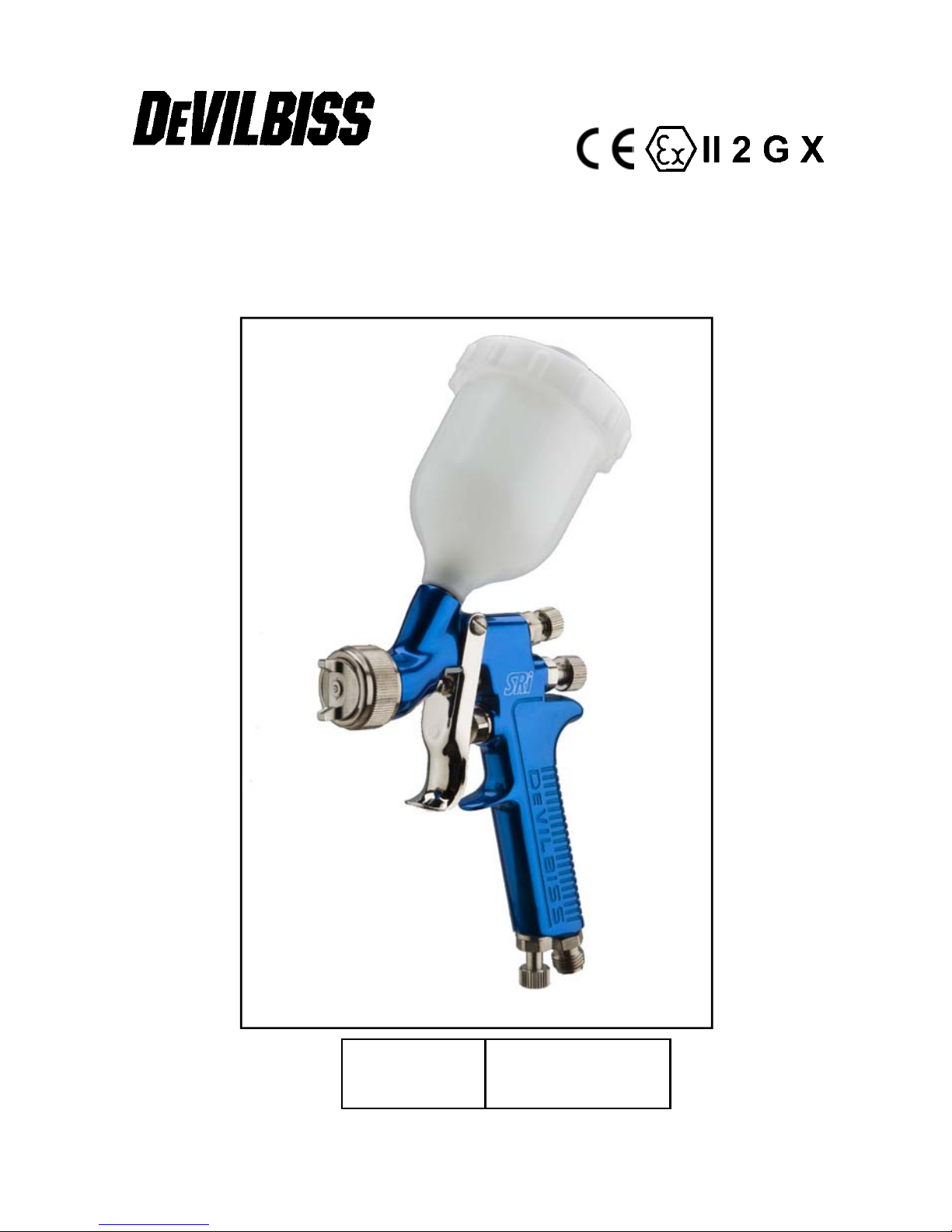
SRi – Gravity Spraygun
ISS.04
E
E
P 2 - 8
Page 2
EE
Operation Manual
Devilbiss SRi – Gravity Spraygun
Important
Read and follow all instructions and Safety Precautions before using
this equipment
Description
The Devilbiss SRI is a small Gravity fed Spraygun designed for spraying spot repairs
and small areas. It is approved to ATEX regulations 94/9/EC, protection level;
II 2 G X, Suitable for use in Zones 1 and 2
Important: These Sprayguns are suitable for use with both waterbased and solvent based
coating materials. The design uses EPA compliant atomising (Devilbiss Trans-Tech®)
technology to reduce overspray and improve coating efficiency. Nozzles and Needles are
manufactured in Stainless Steel. These guns are not designed for use with highly corrosive
and/or abrasive materials and if used with such materials it must be expected that the need for
cleaning and/or replacement of parts will be increased. If there is any doubt regarding the
suitability of a specific material contact your local Distributor or ITW Finishing direct.
Model Part Number
Example: SRI-G210B-08
Fluid nozzle size
Aircap
(08 = 0,8 mm)
EC Declaration of Conformity
We: ITW Finishing UK, Ringwood Rd, Bournemouth, Dorset, BH11 9LH, UK, as the
manufacturer of the Spraygun model SRi, declare, under our sole responsibility, that the
equipment to which this document relates is in conformity with the following standards or other
normative documents:
BS EN 292-1 PARTS 1 & 2: 1991, BS EN 1953: 1999; and thereby conform to the
protection requirements of Council Directive 98/392/EC relating to Machinery Safety Directive,
and;
EN 13463-1:2001, council Directive 94/9/EC relating to Equipment and Protective
Systems intended for use in Potentially Explosive Atmospheres protection level II 2 G X.
This product also complies with the requirements of the EPA guidelines, PG6/34.
Transfer efficiency certificates are available on request.
ITW Finishing Systems and Products reserve the right to modify equipment specification without prior notice.
© 2003 ITW Finishing Systems and Products
2
B. Holt, General Manager
30th June 2003
Page 3
SAFETY WARNINGS
EE
Fire and explosion
Solvents and coating materials
can be highly flammable or
combustible when sprayed. ALWAYS
refer to the coating material suppliers
instructions and COSHH sheets
before using this equipment
Users must comply with all local
and national codes of practice
and insurance company
requirements governing
ventilation, fire precautions, operation
and house-keeping of working areas
This equipment, as supplied,
is NOT
Halogenated Hydrocarbons
Static Electricity can be
generated by fluid and/or air
passing through hoses, by the
spraying process and by cleaning nonconductive parts with cloths. To prevent
ignition sources from static discharges,
earth continuity must be maintained to
the spraygun and other metallic
equipment used. It is essential to use
conductive air and/or fluid hoses.
suitable for use with
.
Personal Protective
Equipment
Toxic vapours – When sprayed,
certain materials may be
poisonous, create irritation or be
otherwise harmful to health.
Always read all labels and safety data
sheets for the material before spraying
and follow any recommendations. If In
Doubt, Contact Your Material Supplier
The use of respiratory protective
equipment is recommended at all
times. The type of equipment
must be compatible with the material
being sprayed.
Always wear eye protection when
spraying or cleaning the spraygun
Gloves must be worn when
spraying or cleaning the
equipment
Training – Personnel should be given
adequate training in the safe use of
spraying equipment.
Misuse
Never aim a spraygun at any part of the
body
Never exceed the max. recommended
safe working pressure for the equipment
The fitting of non-recommended or nonoriginal spares may create hazards
Before cleaning or maintenance, all
pressure must be isolated and relieved
from the equipment
The product should be cleaned using a
gun washing machine. However, this
equipment should not be left inside gun
washing machines for prolonged periods
of time.
Noise Levels
The A-weighted sound level of
sprayguns may exceed 85 dB
(A) depending on the set-up
being used. Details of actual
noise levels are available on request. It is
recommended that ear protection is worn
at all times when spraying.
Operating
Spray Equipment using high pressures
may be subject to recoil forces. Under
certain circumstances, such forces could
result in repetitive strain injury to the
operator.
3
© 2003 ITW Finishing Systems and Products
Page 4
EE
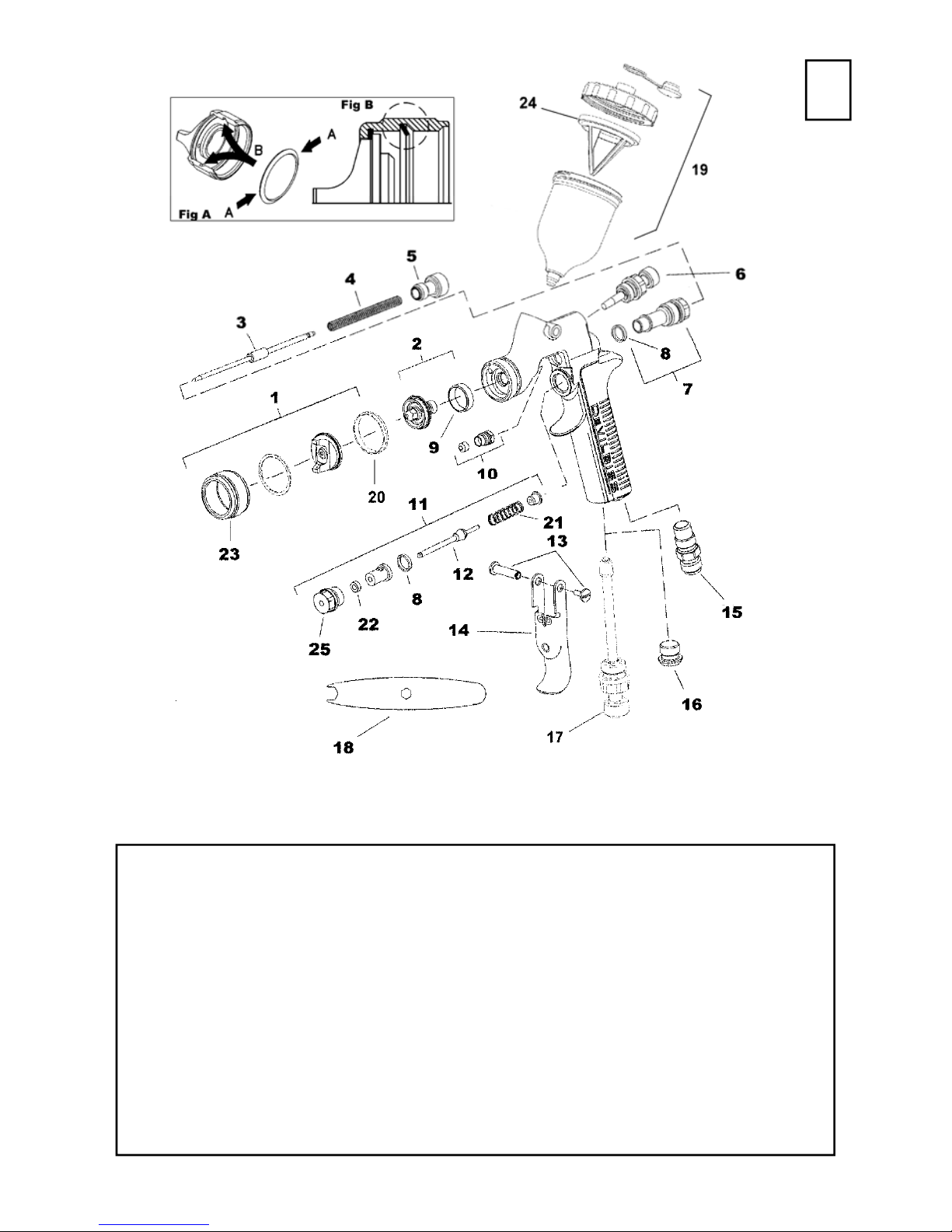
Parts List
Ref. No Description Part Number Qty
1
+2
+3
*4 Needle Spring SRI-18-K2 1
5 Needle Adjusting Knob SRI-19-K2 1
6 Spreader Valve SRI-401-K 1
7 Body Bushing and Seal Kit SRI-17-K 1
*8 Seal SRI-16-K5 1
*9 Separator SRI-6-K5 1
*10 Needle Packing Kit of 3 SRI-411-K3 1
11 Air Valve Assembly SRI-404-K 1
Air Cap/Retaining ring HVLP SRI-407-205 1
Air Cap/Retaining ring Compliant SRI-407-210 1
Nozzle 0.7 mm seal SRI-2-07-K 1
Nozzle 0.8 mm seal SRI-2-08-K 1
Nozzle 1.0 mm seal SRI-2-10-K 1
Nozzle 1.2 mm seal SRI-2-12-K 1
Needle for 1.0 and 1.2 mm Nozzle SRI-3-K 1
Needle for 0.7 and 0.8 mm Nozzle SRI-37-K 1
12 Air Valve Stem Assembly - 1
13 Trigger Stud and Screw Kit SRI-412-K 1
14 Trigger SRI-9-K 1
15 Air Inlet Adaptor SRI-20-K 1
16 Blanking Plug (to replace airflow valve) SRI-21 1
17 Airflow Valve SRI-402-K 1
*18 Spanner SRI-50-K2 1
19 Cup and Lid Kit of 12 SRI-510 1
*20 Aircap Seal SRI-35-K5 1
*21 Airvalve Spring SRI-23-K2 1
*22 Airvalve Seal - 1
23 Retaining Ring - 1
24 Filter —Kit of 3 SRI-42-K3 1
25 Airvalve Body - 1
Parts marked with * are contained in the service Kit SRI-416
+ SRI-440-07
© 2003 ITW Finishing Systems and Products
4
Page 5
EE
Patent No 2372465 (GB)
Air supply connection - Universal 1/4“ BSP and NPS (M)
Maximum Static Air inlet pressure - P
Nominal gun Air inlet pressure with gun
triggered - 2 bar (29 psi)
Gun Weight (with Cup and Lid) - 390g
Maximum Service temperature - 40°C
Materials of Construction for wetted parts
Gun body - Anodised Aluminium
Nozzle - Stainless steel
Needle - Stainless Steel
Cup - Anti-static Acetal
Cup Lid - Anti-static Acetal
Specification
= 9 bar (130 psi)
1
5
© 2003 ITW Finishing Systems and Products
Page 6
EE
Installation
Important: To ensure that this equipment
reaches you in first class condition,
protective coatings have been use. Flush
the equipment through with a suitable
solvent before use.
1. Attach air hose to connector (15).
Recommended hose size 8 mm
Operation
1. Mix coating material to manufacturers
instructions.
2. Screw Cup (19) to Gun. Do not over
tighten.
3. Place the filter (24) in the cup and fill
to required level with paint, or use
funnel (SRI-17) and use paper filter.
Screw on lid.
4. Turn needle adjusting screw (5) fully
clockwise to shut off fluid (for setting
up air supply pressure).Turn spreader
valve (6) counter-clockwise to fully
open.
5. Attach air supply to Gun and adjust
inlet air pressure up to 2 bar (29psi) at
the gun inlet with the gun triggered.
(pressure gauge attachments shown
under Accessories are recommended
for this).
6. Turn Needle Adjusting Screw anticlockwise 2 turns to find the mid
position.
7. Test spray. If the finish is too dry
reduce airflow by reducing inlet
bore. The hose must be conductive
and electrical bond from the
spraygun to earth should be checked
with an ohmeter. A resistance of less
than 10
2. Air supply should be filtered and
regulated.
pressure. If finish is too wet reduce
fluid flow by turning needle screw (5)
clockwise. If atomisation is too
coarse, increase inlet air pressure. If
too fine reduce inlet pressure.
8. The pattern size can be reduced by
turning Spreader valve (6) clockwise.
9. Hold gun perpendicular to surface
being sprayed. Arcing or tilting may
result in uneven coating.
10. The recommended spray distance is
75-150 mm (3”-6”).
11. Spray edges first. Overlap each
stroke a minimum of 50%. Move gun
at a constant speed.
12. Always turn off air supply and relieve
pressure when gun is not in use.
Air Flow Valve (17)
1. The airflow valve (17) is fitted to
reduce the inlet pressure through the
gun. Screw the Adjusting Knob
clockwise to reduce pressure.
6
Ω is recommended.
Preventative Maintenance
1. Turn off air supply and relieve
pressure in the airline, or if using QD
system, disconnect from airline.
2. Empty coating material into a
© 2003 ITW Finishing Systems and Products
suitable container and clean the gun
and cup, preferably in a gun wash
machine.
3. IMPORTANT– the cup must not be
6
Page 7

EE
cleaned or rubbed with a dry cloth
or paper. It is possible to generate
a static charge, by rubbing, which
if discharged to an earthed object
could create an incendive spark
and cause solvent vapours to
ignite. Only use a dampened cloth
or antistatic wipes if additional
cleaning is required in a
Hazardous area.
4. Remove air cap and clean. If any of
the holes in the cap are blocked with
Replacement of Parts
Spanner (18) - The spanner is provided
for removal of the Nozzle (2) with the
centre hex and the adjustment of the
Needle Packing (10) with the open end.
Aircap (1) - Unscrew Aircap from the
Spraygun. Remove seal (20). Remove
Aircap from the Retaining Ring (23).
Clean Aircap and Ring. Re-assemble
Aircap to Retaining Ring (23). Fit new
Seal (20) as in Fig A on exploded view,
by lightly squeezing and inserting into
the ring. Make sure the seal is fitted the
correct way round as in Fig B.
Nozzle (2) and Needle (3) – Remove
parts in the following order: (5), (4), (3),
(1), (2) and (9). Replace any worn or
damaged parts and re-assemble in
reverse order. It is recommended that
the Separator (9) is replaced whenever
the Tip (2) is removed. Recommended
tightening torque for nozzle (2) 9 Nm (80
lbf in).
Packing (10) – Remove parts (5), (4),
(3). Unscrew cartridge (10). Fit new
cartridge finger tight. Re-assemble parts
(3), (4), and (5) and tighten cartridge
(10) with spanner (18) sufficient to seal
but to allow free movement of needle.
Lubricate with gun oil.
coating material use a toothpick to
clean. Never use metal wire which
could damage the cap and produce
distorted spray patterns.
5. Ensure the tip of the nozzle is clean
and free from damage. Build up of
dried paint can distort the spray
pattern.
6. Lubrication – stud/screw (12/13), nee-
dle (3) and air valve (11) should be
oiled each day.
Air valve (11) – Remove trigger (14).
Remove body (25) and withdraw
complete valve. Remove rear bush,
spring and Stem assembly. Remove the
Airvalve Cage from the Valve body and
remove seal (22). Replace new seal
(22), making sure the seal is correctly
fitted with the lip facing inwards.
Remove old seal (8) from body if left in
place. Place new seal (8) on the cage
before replacement of the Valve
assembly. Slide Stem assembly (12) into
the cage assembly, fit the spring (21) on
the valve head and fit collar. Fit
complete assembly to Gunbody.
Spreader valve (6) – Caution: always
ensure that the valve is in the fully open
position by turning screw fully counterclockwise before fitting to body.
Air cap / Nozzle Selection
Refer to coating material manufacturers
recommendations or ITW Finishing UK
Website:
www.itweuropeanfinishing.com
7
© 2003 ITW Finishing Systems and Products
Page 8
EE
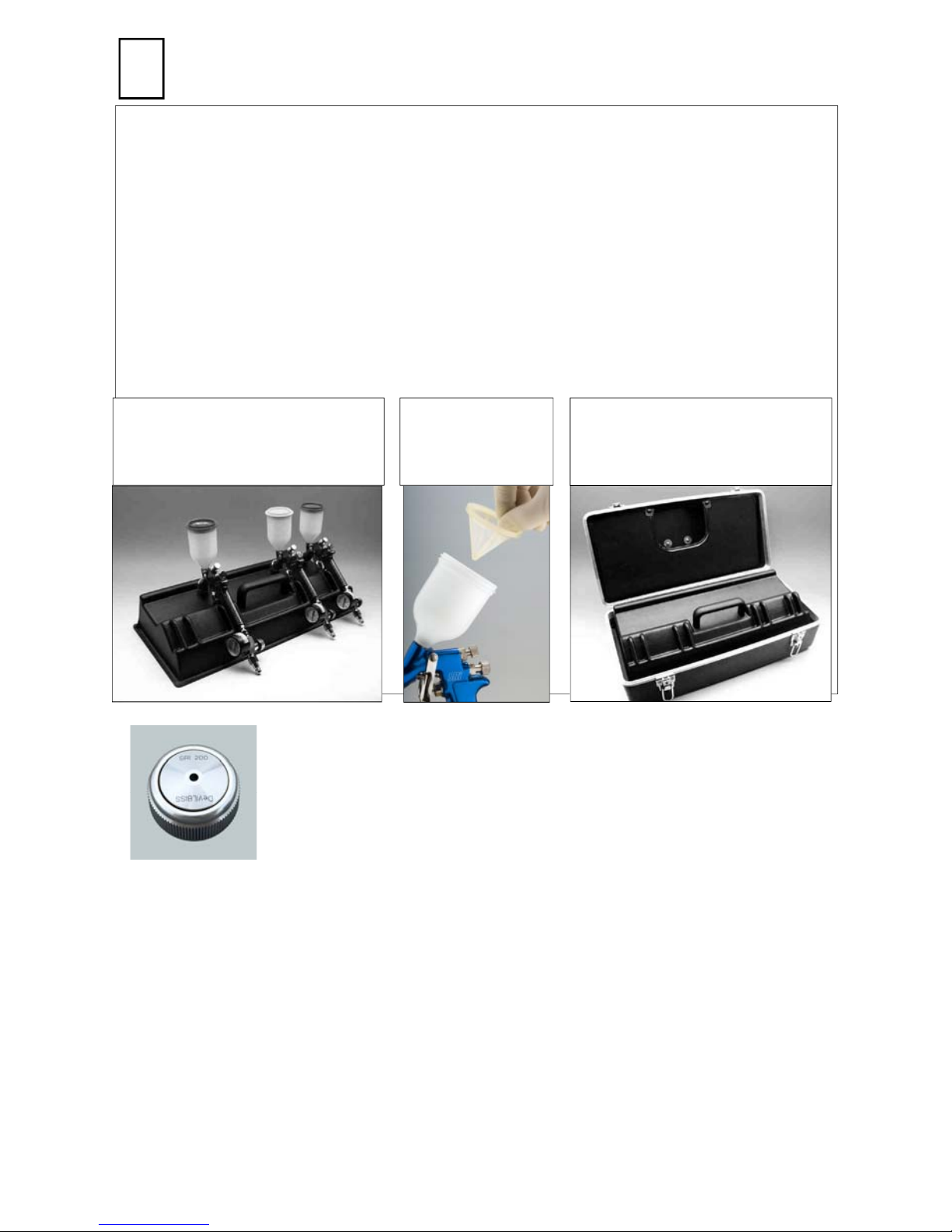
Accessories
Aircap, Tip and Needle set - SRI-450-***-** (*** = Aircap No, ** = Tip size)
Spanner – SRI-50-K2
Cleaning Brush – SRI-65-K2
Service Kit – SRI-416
Gun Mounted Regulator with Mini QD– HAV-601
Lubricant - GL-1-K10
SRI-478-K3 Black Cup and Lid set (3 sets) - suitable for use with UV curing
paints.
SRI-51-K12 Funnel kit of 12
SRI-100 - Gun Carry tray
(Guns not included)
Roundspray Aircap - SRi-407-200
HVLP Mode - Air Inlet Pressure = 1.2 Bar (17.5 PSI)
Tanstech Mode – Air Inlet Pressure = 2 bar (29 PSI)
Approx Spot Size = Ø40mm
SRI-42-K3
Filter kit of 3
SRI-410 - Carry case for
up to 3 Guns, with SRI-100
Tray
ITW Finishing Systems and Products
Ringwood Road,
Bournemouth,
BH11 9LH,
England.
Tel. No. (01202) 571111
Telefax No. (01202) 581940,
Website address http://www.itweuropeanfinishing.com
ITW Oberflächentechnik GmbH & Co. KG
Justus-von-Liebig-Straße 31
63128 Dietzenbach
Tel (060 74) 403-1
Telefax: (060 74) 403300
Website address http://www.itw-finishing.de
© 2003 ITW Finishing Systems and Products
ITW Surfaces Et Finitions
163-171 avenue des Auréats B.P. 1453
26014 VALENCE CEDEX FRANCE
Tél. (33) 475-75-27-00
Télex 345 719F DVILBIS
Téléfax: (33) 475-75-27-99
ITW Finishing Systems and Products is a Division of ITW Ltd.
Reg. Office:
Admiral House,
St Leonard’s Road,
Windsor,
Berkshire,
SL4 3BL,
UK
Registered in England: No 559693 Vat No 619 5461 24
8
February 06
 Loading...