

DeVilbiss SolAiris III 30307, SolAiris III 30305, SolAiris III 303CZ, SolAiris III 303CS User manual
Page 1
Solâiris
Ш.
Oxygen
Concentrator
Service
30307,
303CZ,
and
Series
Manual
Models
30305,
303CS
LT-1691
©
1996
Rev.
DHC,
A
Inc.
Page 2
я
nf
=
©
—
=
©
©
ドー
©
©
で
pm
Table
General
introduction
Warranty
ImportantSafeguards.....................................
Safety
Theory
-Operation/Installation
SolAiris
Microprocessor-Controlled
OSD
SolAiris
Exterior
Specifications
Operating
Performing
Suggested
Maintenance
of
Information
Information
Precautions
of
Operation
Operation
Option
III
Overview
and
the
Initial
Patient
Contents
Interior
.....................
SolAiris
Inspection
Setup
and
Parts
General
Photos
III...
Warnings
Pressure-Sensing
e.
..
....
System
Patient
Patient
Diagnostic
Troubleshooting
Normal
Simplified
Troubleshooting
OSD
Component
Proper
Leak
Cabinet
Power
Flow
Pressure
Sieve
Final
Molecular
Compressor
Cooling
Four-Way
Printed
Capacitor
OSD
Ordering
Alert & Diagnostic
Alert
System
System
Operating
Troubleshooting
Troubleshooting
Testing,
Repair
Testing
Removal...
Cord...................
Meter
Regulator
Bed
Check
Check
(oxygen
Valve
Sieve
...........
Fan
Valve
Circuit
Information
Sequence...
Chart
Chart
Repair,
Procedures...
....
Valves......
........
Beds
..............
Board
sensing
device)
and
System
.
and
Parts
Replacement
List..
Page 3
General
Introduction
This
service
maintenance,
in-depth
school
manual
service,
classroom-type
information,
Information
was
created
and
training,
contact
repair
the
Service
for
DeVilbiss
procedures
DeVilbiss
Department
on
holds
qualified
the
service
SolAiris
oxygen
at
1-800-338-1988.
technicians
III
Oxygen
concentrator
to
define
Concentrator.
service
schools.
the
For
For
proper
more
service
EU
©
=
ο
=
5
Warranty
SolAiris
The
SolAiris
warranted
directly
This.equipment
as
stated
*
Valving
¢
OSD
+
All
¢
Routine
DeVilbiss’
Authorized
under
an
will
remove
container,
This
DeVilbiss,
ranty
Service Center.
this
Authorized
be
warranty
must
information
III
Limited
III
Oxygen
as
stated
from
DeVilbiss,
below
warranted
warranted
other
maintenance
obligation
Service
warranty,
Service
issued.
the
For
defective
properly
does
in
removing
be
performed
Warranty
Concentrators,
below.
or
is
warranted
from
date
of
for
for
the
components
under
Center
the
original
Center.
component
component
identify
not
cover
or
replacing
by a qualified
manufactured
This
warranty
through
shipment
the
warranted
items,
this
or
by a Return
its
by
DeVilbiss
life
of
life
of
the
such
warranty
supplying a replacement
purchaser
The claim
part(s)
part(s),
the
cost
the
extends
Providers,
to
be
free
by
DeVilbiss
the
unit.
unit
(OSD
for
three
as
filters,
is
limited
must
will
be
return(s),
properly
Authorization
of
labor
warranty
DeVilbiss
it
incurred,
and
sold
only
to
the
Buyer
Distributors,
from
to
the
models
years.
are
excluded
to
the
for
notify
evaluated
shall
package
Number,
component
provider
or
defects
original
only).
option
component
DeVilbiss
and,
be
the
responsibility
in a DeVilbiss
either
by
part(s).
and/or
by
DeVilbiss
purchasing
Agents,
in
workmanship
purchaser:
from
Warranty.
of
repairing
part(s).
at
its
if
bona
and
to
the
homecare
Service
an
Authorized
Health
as
New
at
plant
in
fide,
further
of
approved
make
shipment
under
Care,
the
equipment
equipment.
and
materials
its
plant
To
make
Somerset,
instructions
the
provider
shipping
provider
this
DeVilbiss
Inc.
are
or
an
claim
PA
or
to
prepaid.
or
war-
=
©
=
3
5
=
©
=>
NOTE—This
trator
NOTE—Replacement
be
This
warranty
*
*
*
+
+
that
warranted
This
equipment
operating
Routine
service
The
equipment
components
The
equipment
The
filters
filters
warranty
is
being
for
shall
not
is
and
service
maintenance,
personnel.
has
(i.e.,
fails
that
were
approved
by
does
repaired
components
the
unexpired
apply,
not
regenerated
and
operated
instructions.
servicing,
been
repaired
resulting
used
on
DeVilbiss.
not
obligate
with a loaner
do
not
portion
DeVilbiss
and
sieve
from
the
unit
shall
maintained
and
repair
or
altered
material).
misuse,
were
DeVilbiss
unit
carry a new
of
the
original
be
relieved
in
accordance
is
not
performed
by
the
use
abuse,
not
negligence,
authorized
to
replace
during
the
warranty
Limited
of
any
obligation
by
of
non-authorized
or
DeVilbiss
an
oxygen
time
of
and
Warranty.
with
DeVilbiss
qualified
accident;
filters
concen-
repair.
shall
or
DeVilbiss
parts
and
or
only
liability
or
quality
if:
Page 4
=
2
~
に
=
im
£
=
Г:
|
È
=
©
©
General
THERE
MERCHANTABILITY
DURATION
ANY
AND
WARRANTIES
STATES
THE
ABOVE
This
from
DeVilbiss
DeVilbiss
free
our
turned
otherwise
IS
NO
OTHER
OF
AND
ALL
LIABILITY
ARE
DO
NOT
LIMITATION
LIMITATION
warranty
state
to
state.
Labor
backs
three-year
Somerset,
to
*
Labor
(provider).
ο
Routine
PA
our
other
stipulated:
warranty
maintenance
THE
IMPLIED
gives
up
labor
Information
EXPRESS
AND
EXPRESS
FOR
CONSEQUENTIAL
EXCLUDED
ALLOW
OR
EXCLUSION
OR
you
Warranty
its
reputation
warranty
facility
authorized
is
effective
WARRANTY.
FITNESS
WARRANTIES
LIMITATIONS
EXCLUSION
specific
or
an
items,
FOR
LIMITED
TO
THE
OF
legal
for
when
Authorized
service
from
such
unexcelled
the
IMPLIED
A
PARTICULAR
WARRANTY
ARE
EXCLUDED.
AND
EXTENT
ON
HOW
CONSEQUENTIAL
MAY
NOT
rights,
centers
date
and
unit
DeVilbiss
of
as
filters,
AND
INCIDENTAL
EXCLUSION
LONG
APPLY
you
product
or
components
are
not
shipment
are
WARRANTIES,
PURPOSE,
TO
THE
THIS
IS
DAMAGES
IS
AN
IMPLIED
OR
INCIDENTAL
TO
YOU.
may
also
quality
under
Warranty
covered
from
excluded.
Center.
by
DeVilbiss
INCLUDING
ARE
LIMITED
EXTENT
THE
EXCLUSIVE
UNDER
PERMITTED
WARRANTY
have
other
and
reliability
warranty
Repairs
our
free
to
THOSE
TO
PERMITTED
REMEDY
ANY
BY
LAW.
DAMAGE,
rights
labor
original
which
by
extending
are
returned
to
units
policy
OF
THE
BY
LAW
AND
ALL
SOME
LASTS,
purchaser
SO
THE
vary
re-
unless
OR
to
a
Optional
The
Extended
manship
ment
Under
the
units
unless
A
$50
Extended
Optional
by
+
Valving
*
OSD
*
Routine
the
unit
returned
otherwise
charge
Note—International
Extended
Warranty,
and
materials
DeVilbiss
warranted
Optional
or
components
for
Warranty
Warranty
the
equipment
for
to
the
warranted
for
maintenance
Extended
under
to
our
other
stipulated.
the
Optional
(303
a
period
original
for
the
authorized
warranties
purchaser.
the
life
life
of
items,
Warranty
warranty
Extended
Extended
must
be
is
warranted
of
five
of
the
the
unit
such
service
Warranty)
selected
years,
unit.
(OSD
as
filters,
you
will
are
returned
centers
Warranty
may
vary.
at
time
by
DeVilbiss
except
models
are
excluded
receive
to
our
are
will
be
Part
of
purchase.
as
stated
only).
a
free
Somerset,
not
covered
added
#303EXTWAR
to
be
free
below,
from
Warranty.
five-year
PA
by
to
your
Under
from
defects
from
labor
warranty
facility.
our
free
invoice
the
Optional
date
Repairs
labor
at
billing.
in
of
ship-
work-
when
to
policy
Page 5
General
Important
Read
all
highlighted
WARNING—important
serious
Safeguards
instruction
by
these
injury.
Information
before
operating
terms:
safety
the
oxygen
information
concentrator.
for
hazards
Important
that
might
information
cause
is
©
O
=>
©
=
2
CAUTION—information
NOTE--information
Safety
A.
B.
C.
D.
Е
G.
H.
Precautions
Federal
Oxygen
a
minimum
use
Do
and
Do
switch;
Do
Only
filter
Electric
by a qualified
Disconnect
Extra
removed.
(U.S.A.)
promotes
person
receiving
of
five
in
rooms
not
then only a bubble-type
not
not
operate
is
care
heated
place a humidifier
connect
the
outlet
use
an
the
wet.
shock
hazard.
the
should
for
preventing
to
which
and
law
restricts
rapid
burning.
oxygen
feet
from
by
paraffin
the
oxygen
should
electrical
oxygen
DeVilbiss
power
be
be
adapter
Do
homecare
cord
taken
damage
you
should
General
this
therapy.
hot,
with
humidifier
concentrator
independent
concentrator
not
remove
from
if
it is
Warnings
device
Do
not
Do
sparking,
or
portable
an
oxygen
or
extension
cabinet.
provider.
the
wall
necessary
pay
to
sale
smoke
not
or
patient
should
to
of
with
outlet
to
the
special
by
or
when
operate
burning
gas
heaters.
unless
be
used.
an
electrical
other
appliances.
cord
with
all
filters
The
before
to
operate
product.
attention.
on
the
order
using
the
oxygen
objects
in
cabinet
attempting
the
or
prescribed
outlet
the
oxygen
place;
may
unit
of a physician.
this
unit
or
concentrator
naked
controlled
do
with
flames.
by a physician
concentrator.
not
operate
only
be
repairs
the
cabinet
when
near
within
Do
by a wall
if
the
removed
on
the
unit.
a
not
air
=
©
=
=
a
=.
に
=
I.
J.
K.
Use
L.
Theory
An
oxygen
applications.
Room
The
delivery
N
air
concentrator draws
Do
not
use
Use
only
When
come
Do
replacing
in
only
not
use
of
Operation
concentrator
is a mixture
of
the
concentrated
oils,
greases,
materials
the
contact
DeVilbiss
with
regenerated
is a device
of
78%
in
or
that
are
capacitor,
the
terminals
Health
the
Care
sieve
nitrogen,
air,
separates
oxygen
any
petroleum-based
compatible
do
not
touch
on
the
concentrator
material.
that
delivers
21%
oxygen, 1%
the
to
the
patient
with
oxygen.
the
capacitor.
replacement
highly
nitrogen
through
solvents/cleaners
terminals
concentrated
argon
from
the
or
allow
parts
、
and
other
the
oxygen,
oxygen
and
oxygen
port.
on
or
near
the
metal
gases.
objects
accessories.
for
therapeutic
and
allows
unit.
to
Page 6
=
©
uje
で
で
Pas
w
=
``
=
Ro)
pari
©
上
二
トリ
©
ο
Operation/Installation
SolAiris
The
SolAiris
filter
and
The
compressed
The
sieve
silicate.
as
it
passes
As
one bed
The
vacuum
its
pressurization
four-way
compressor.
orifice
The
beds
This
cycling
(A
typical
Oxygen
A
pressure
and
enters
adjusted
passes
Operation
III
into
beds
It is
very
through
is
being
process
and
Also
into
the
will
continue
process
cycle
leaving
regulator
the
to
the
through
uses
a
pressure-vacuum
a
double-head
air
passes
contain
is
released
bed
time
the
flow
level
the
molecular
porous
the
pressurized
removes
cycle.
during
being
to
will
at
sieve
on
meter.
prescribed
final
compressor.
through
and
has
sieve
bed.
and
the
The
nitrogen
through
each
bed
evacuated.
be
alternately
vary
in
length
3
LPM
is
approximately
beds
is
directed
the
tank
controls
The
flow
by
bacteria
system.
a
four-way
sieve
material
the
unique
:
producing
nitrogen
being
an
exhaust
pressurization,
This
pressurized
depending
through
the
meter
the
patient's
filter,
check
The
valve
ability
oxygen,
from
the
evacuated
muffler
helps
purge
oxygen
allows
physician.
valve,
air
and
which
to
sieve
located
a
small
and
on
altitude
8
seconds
a
check
pressure
the
oxygen
and
is
selectively
out
the
is
drawn
is
a
a
vacuum
material
of
amount
nitrogen
evacuated
valve
outlet
into
directed
synthetically
adsorb
the
sieve
on
the
and
at
sea
level.)
to
as
it
flow
From
the
port
the
unit
into
one
produced
nitrogen
is
drawn
that
was
bed
vacuum
of
oxygen
from
the
as
the
oxygen
the
accumulator
leaves
to
the
be
controlled
flow
meter,
to
the
through
of
two
on
the
adsorbed
passes
unit
output
patient.
through
head
flows
bed.
operates.
flow
accumulator
the
the
air
sieve
beds.
inorganic
from
the
air
other
bed.
during
the
of
the
through
tank.
and
oxygen
an
rate.
Microprocessor-Controlled
The
SolAiris
unit.
The
a
pressure
lator
tank
cycle
time
A
cycle
board
the
green
With
the
a
vacuum
accumulator
way
to
sieve
bed
the
PC
process
The
PC
condition
The
alarm
component
III
operates
cycling
transducer
by
1/16"
at
this
change
will
four-way
deactivate
board
is
board
takes
send
12
“4-way”
is
drawn
tank,
and
a
vacuum
is
not
repeated
also
or
when
system
failure.
is
controlled
mounted
diameter
point.
place
VDC
indicator
in
the
on
the
or
go
illuminated
every
activates
the
will
Pressure-Sensing
on
a
microprocessor-controlled
and
tubing
when
to
the
four-way
light
activated
the
right
PC
board
to
the
“rest”
is
drawn
time
the
the
cycle
time
also
activate
monitored
on
the
and
the
pressure
on
the
position,
sieve
bed.
removes
position
on
the
when
PC
board
alarm
has
exceeded
in
PC
board.
allows
valve
PC
When
the
left
the
voltage
senses
system
the
case
System
by
the
PC
The
transducer
the
PC
in
the
accumulator
causing
board
will
compressed
the
PC
12
VDC
from
and
compressed
sieve
bed.
is
removed
15
PSI
whenever
its
preset
of
a
power
pressure-sensing
board.
board
the
illuminate.
air
board
The
in
it
minimum
This
is
to
sense
valve
to
is
directed
senses
the
four-way.
air
is
green
from
the
oxygen
senses
failure
a
and
is
accomplished
connected
the
tank
reaches
activate.
to
15
then
“4-way”
the
valve.
low
or
or
maximum
electrical
system
the
PSI
This
directed
accumulator
to
to
the
oxygen
indicator
high
15
At
the
left
sieve
in
the
causes
to
This
pressure
limits.
or
pressure
cycling
cycle
PSI.
same
oxygen
the
pneumatic
the
by
use
accumu-
and
The
PC
time
bed
and
the
four-
right
light
on
tank.
of
Page 7
Operation
OSD
Option
The
SolAiris
of
oxygen
front
+
*
panel.
III
leaving
Normal
Low
Oxygen
with
the
the
Oxygen
(yellow
accumulator
(green
/Installation
optional
OSD
(oxygen
tank.
light) - oxygen
light) - oxygen
sensing
There
levels
levels
are
two
>85%
<85% + 2% - requires
device)
monitors
additional
+2%
the
concentration
indicator
servicing
lights
on
the
NOTE—If
sound.
SolAiris
This
service
service,
information
tenance
NOTE—DeVilbiss
oxygen
nents
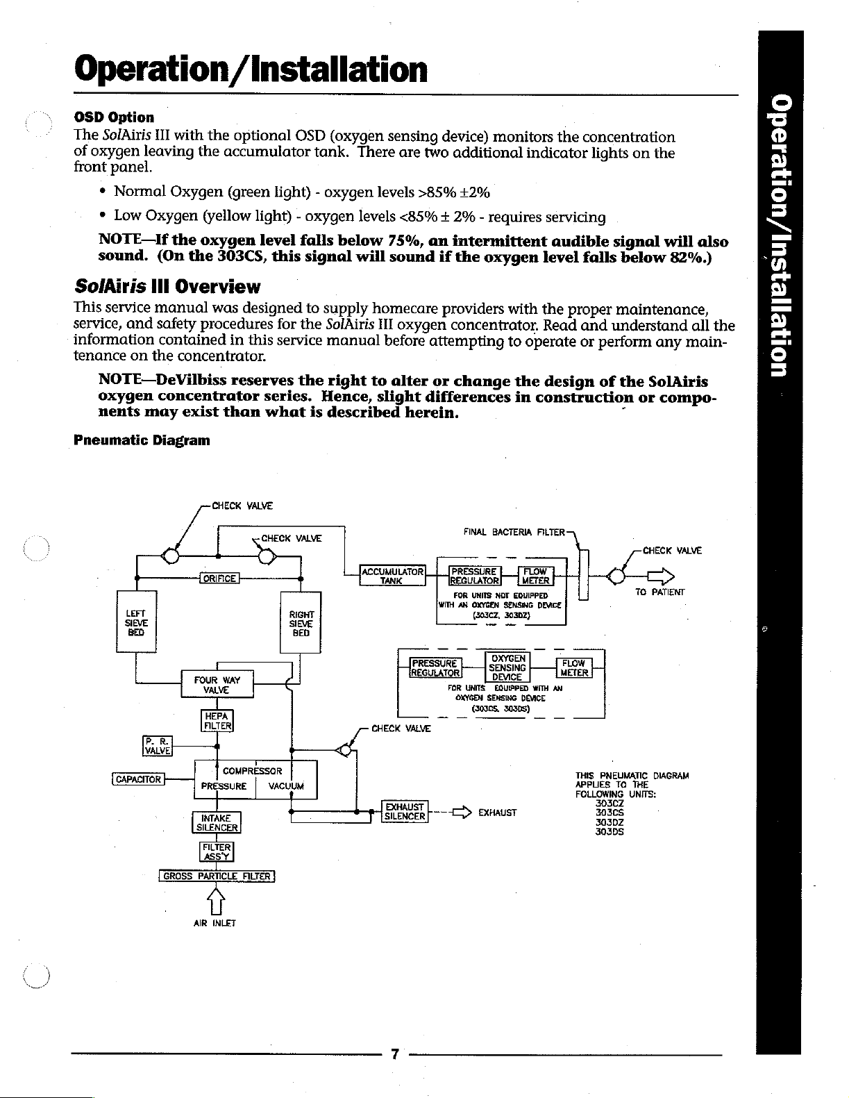
Pneumatic
III
and
on
the
may
Diagram
LEFT
SIEVE SIEVE
BED BED
PR
VALVE
CAPACITOR
the
oxygen
(On
the
303CS,
Overview
manual
safety
contained
concentrator
was
procedures
in
concentrator.
reserves
exist
than
CHECK
A
REE
5
a
πα
Mie
HEPA
FILTER
COMPRESSOR
PRESSURE
j
level
falls
this
designed
for
the
this
service
the
series.
what
VALVE
CHECK
VALVE
RIGHT
て
T
|
VAcu
below
signal
to
supply
SolAiris
manual
right
Hence,
is
described
75%,
an
will
sound
homecare
III
oxygen
before
to
slight
ACCUMULATOR|
CHECK
EXHAUST
SIENCER
attempting
alter
or
differences
herein.
|.
PRESSURE
REGULATOR}
VALVE
ーー
intermittent
if
the
oxygen
providers
concentrator.
change
FINAL
[PRESSURE
FOR
WITH
AN
FOR
OXYGEN
一
一
>
with
to
BACTERIA
UNITS
NOT
OXYGEN
SENSING
(30302.
30302}
Lo
OXYGEN
—
|
SENSINO
UNITS
EQUIPPED
SENSING
(30308,
30308)
EXHAUST
the
in
RIA
[8
EQUIPPED
audible
level
falls
the
proper
Read
and
operate
construction
FILTER
DEVICE
or
design
FLOW
METER
WITH
AN
DEVICE
一
一
THIS
APPLIES
FOLLOWING
signal
below
maintenance,
understand
perform
of
the
or
.
CHECK
TO
any
SolAiris
compo-
PATIENT
PNEUMATIC
30308
0302
303DS
TO
THE
UNITS:
DIAGRAM
will
82%.)
main-
VALVE
also
all
the
4
}ellelsul/uoleedo
©
5
Page 8
=
2
~
で
で
de
[A]
pS
a
<
©
jeď
©
>=
©
о.
©
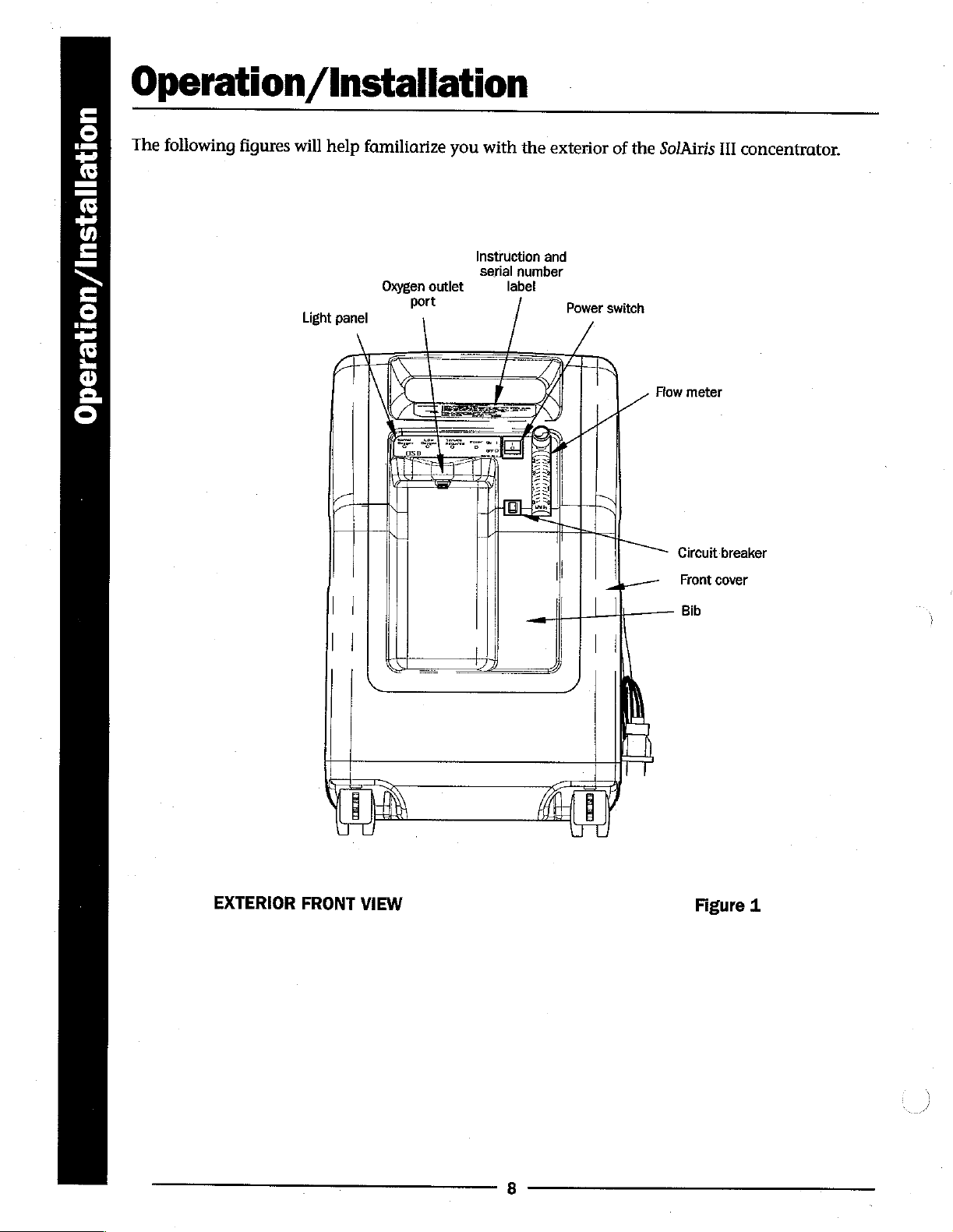
Operation
The
following
figures
will
Light
/Installation
help
familiarize
Oxygen
panel
outlet
port
you
with
Instruction
serial
the
number
label
/
exterior
and
Power
/
"TA
of
the
SolAiris
switch
Flow
meter
II]
concentrator.
EXTERIOR
|
|
| | |
FRONT
VIEW
EN
(O
Circuit
breaker
Front
cover
Bib
Figure
1
Page 9
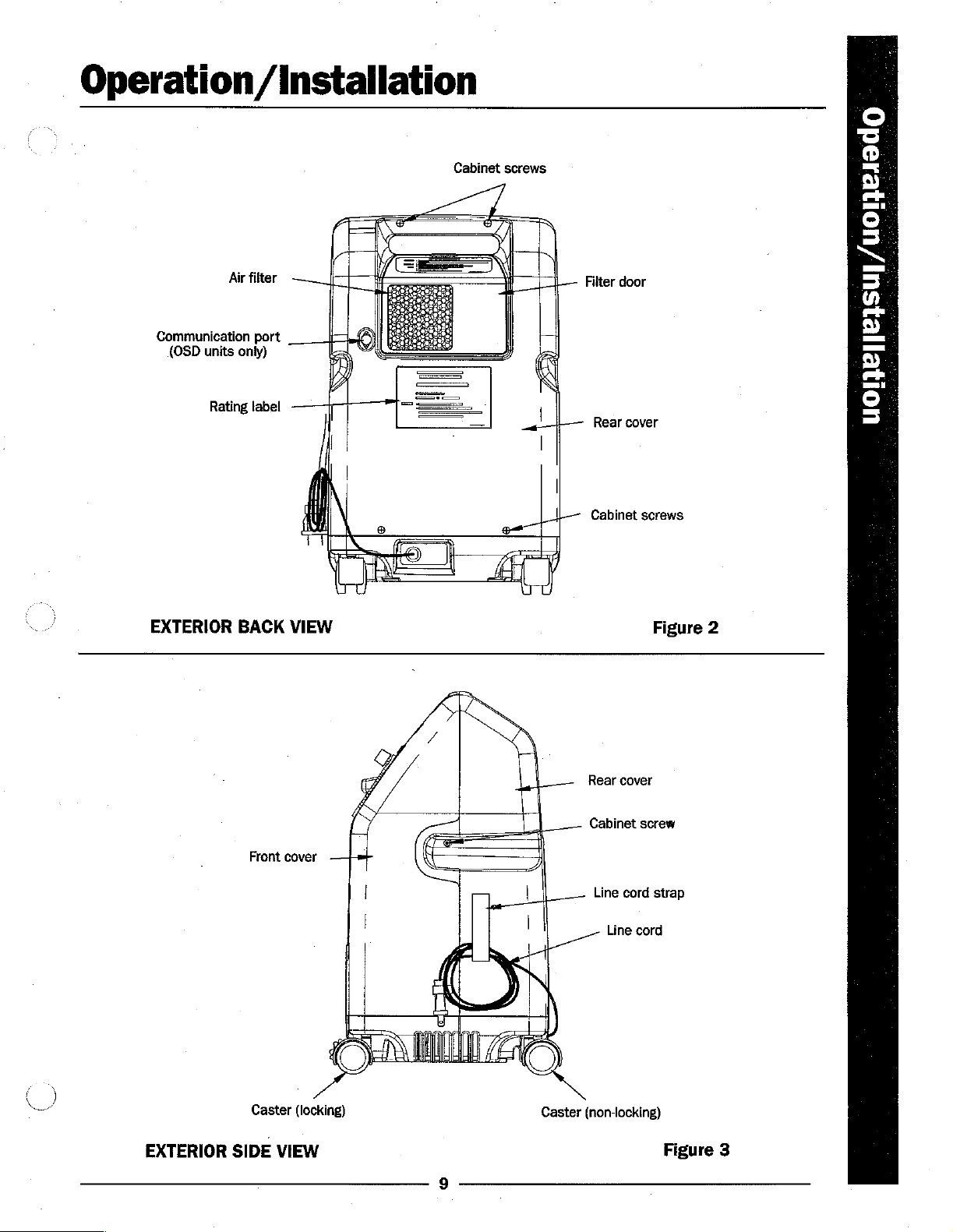
Operation
Air
filter
Communication
(OSD
units
only)
Rating
label
/Installation
Cabinet
port
|
screws
+
|
|
|
Filter
door
Rear
cover
Cabinet
screws
©
=
O.
-
=.
©
CE
に
к}
の
l
>
И
=
©
-
EXTERIOR
BACK
Front
VIEW
cover
一
|
|___
|
|
]
Rear
cover
Cabinet
Line
cord
Figure
screw
strap
2
Line
cord
+7
N
ο”
Caster
(locking)
EXTERIOR
SIDE
VIEW
Caster
(non-locking)
Figure
3
Page 10
=
©
し
で
©
~
0
=
N
=
©
—
©
=
©
©
ο
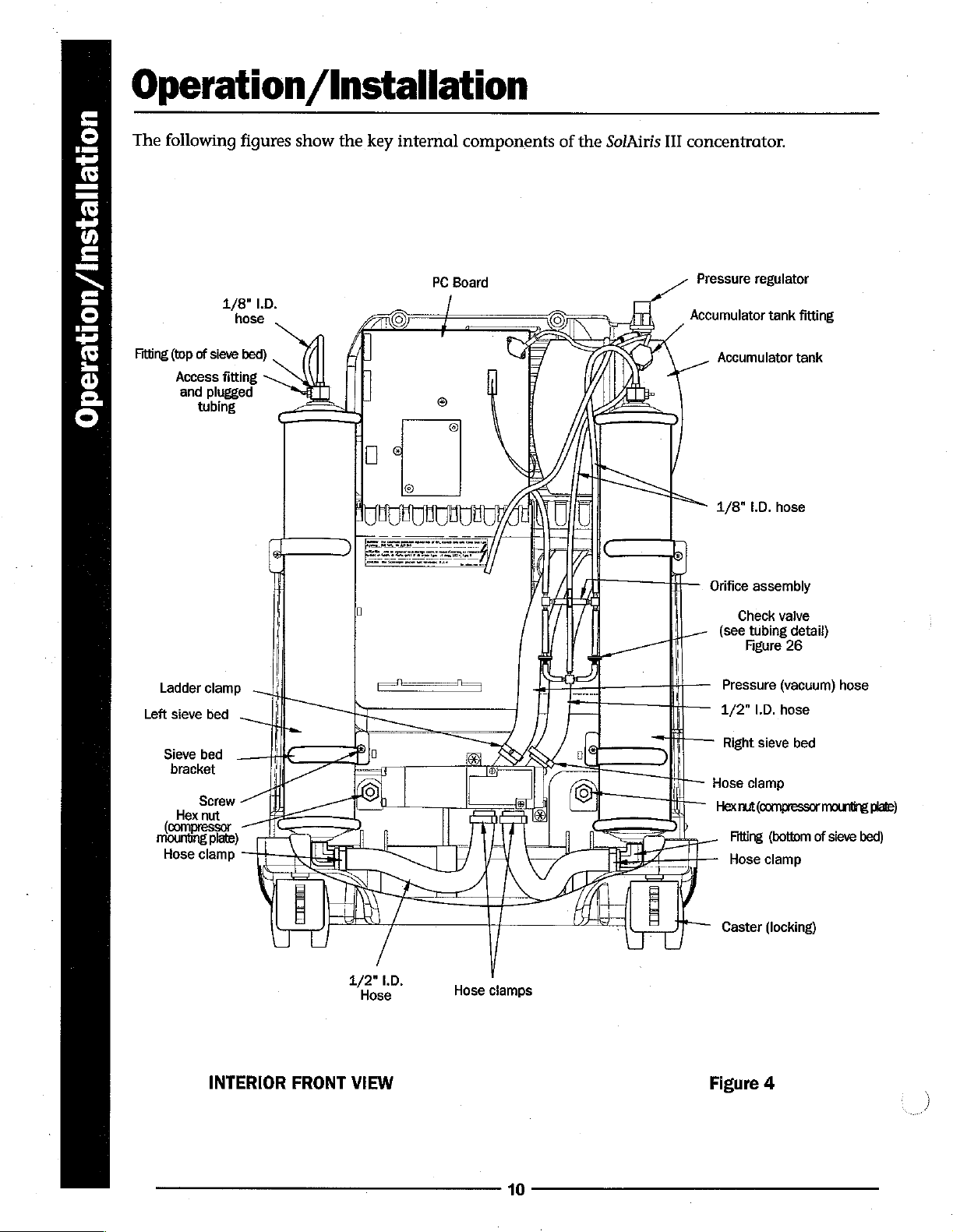
Operation
The
following
ニー』
Fitting
(top
of
sieve
Access
and
plugged
tubing
figures
1/8"
I.D.
hose
bed)
fitting
/Installation
show
the
key
internal
components
PC
Board
of
the
SolAiris
III
concentrator.
Pressure
Accumulator
Accumulator
regulator
tank
fitting
tank
Ladder
clamp — |
Left
sieve
bed — |
Sieve
bed
bracket
Screw < |
Hex
nut
(compressor.
mounting
Hose
plate)
clamp
ή
4
__—¿£
|
n
レレ
—T/C
[SX
1/8"
LD.
нове
一
Orifice
assembly
|
| — (see
|
|
[—~
a
L
Check
Pressure
1/2"
Right
Hose
Hex
nut
Fitting
Hose
Caster
valve
tubing
detail)
Figure
26
(vacuum)
1.0.
позе
sieve
bed
clamp
(compressor
(bottom
clamp
(locking)
hose
mounting
of
sieve
plate)
bed)
1/2"
Hose
INTERIOR
FRONT
VIEW
/
1D.
Hose
|
clamps
10
Figure
4
Page 11
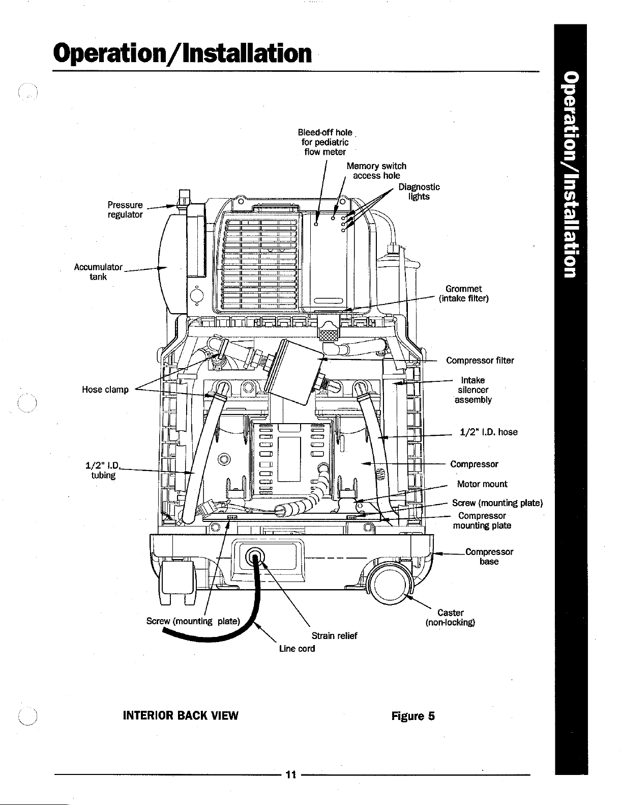
Operation
Pressure
regulator
Accumulator
tank
/Installation
Bleed-off
for
pediatric
flow
meter
hole
Memory
.
access
switch
hole
Diagnostic
lights
Grommet
{intake
filter)
©
で
©
=
W
=
©
=
=
=
mn
i
>
S
=.
©
=
y
Hose
1/2"
tubing
clamp
1.0.
Screw
(mounting
plate)
Line
Strain
cord
relief
Compressor
Intake
silencer
assembly
1/2"
Compressor
Motor
Screw
Compressor
mounting
Compressor
Caster
(nor-locking)
filter
1.D.
hose
mount
(mounting
plate
base
plate)
INTERIOR
BACK
VIEW
11
Figure
5
Page 12
=
©
--]
5
©
Pai
の
=
N
[一
©
=
6
=
©
に
O
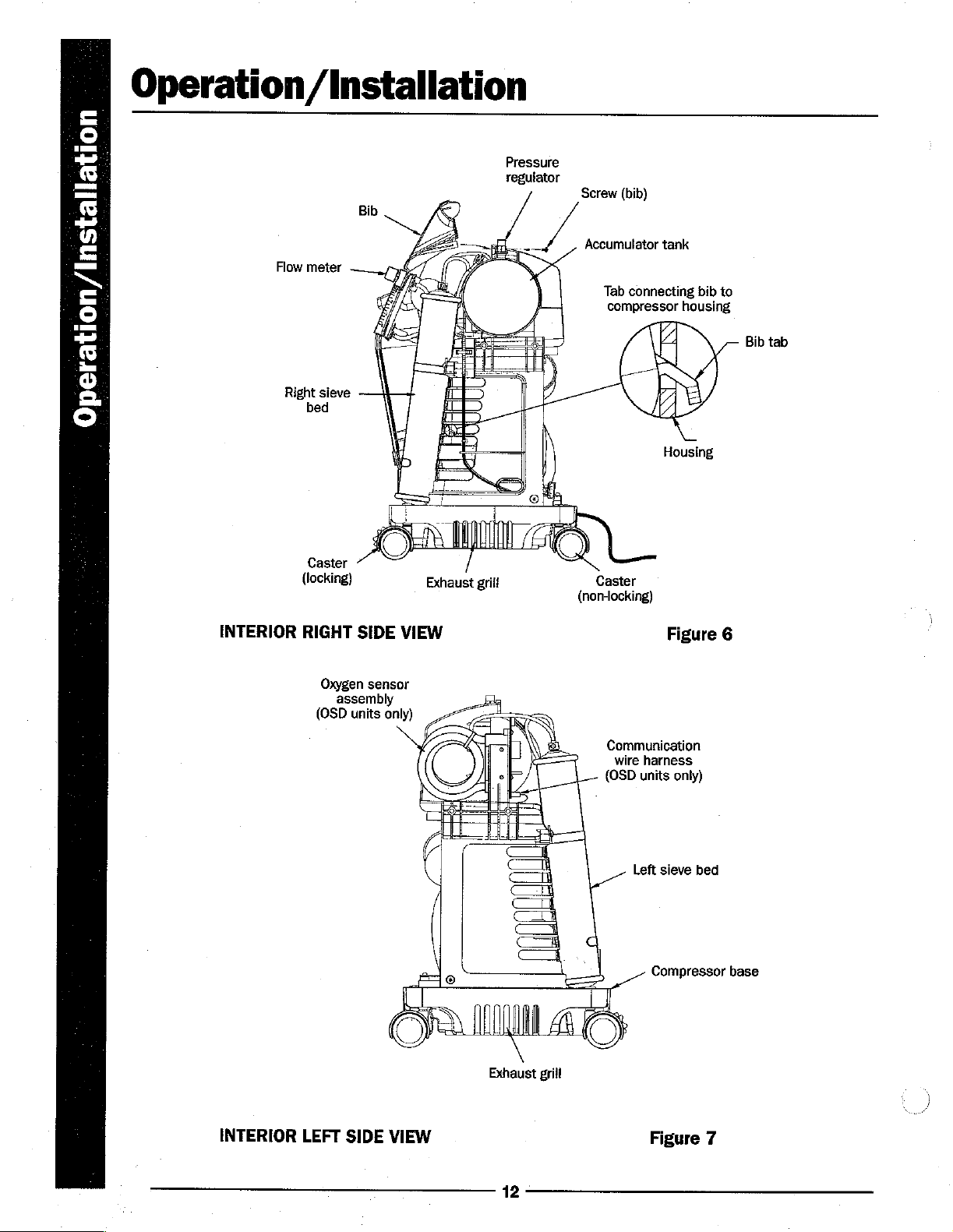
Operation
Flow
Right
/Installation
Pressure
regulator
Bib
meter
sieve
bed
Screw
(bib)
Accumulator
Tab
connecting
compressor
tank
housing
bib
to
Bib
tab
INTERIOR
Caster
(locking)
RIGHT
Oxygen
assembly
(OSD
SIDE
sensor
units
Housing
Exhaust
VIEW
only)
grili
Caster
(non-locking)
Figure
6
Communication
wire
harness
(OSD
units
only)
Left
sieve
bed
INTERIOR
LEFT
SIDE
©
VIEW
Exhaust
12
grill
-
O
Compressor
Figure
base
7
Page 13
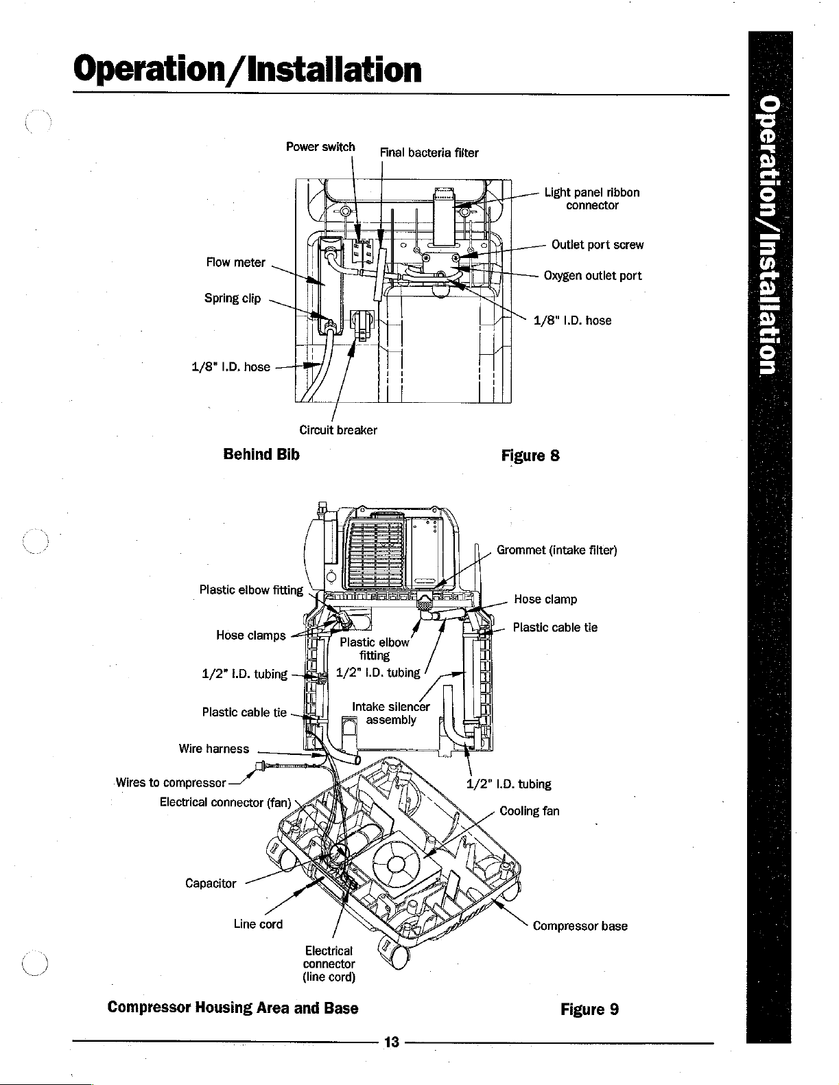
Operation/
Flow
meter
Spring
1/8"
I.D.
Installation
Power
clip
hose
Circuit
switch
breaker
Final
bacteria
filter
Light
Outlet
Oxygen
1/8"
panel
connector
1.0.
ribbon
port
screw
outlet
позе
port
o:
"S
©
|
トリ
Fu
©
—
=
=
a
ea
9
98
=
©:
5
a
ali
X
Wires
Wire
to
compressor
Electrical
Behind
Plastic
H
ose
1/2"
1.D.
Plastic
harness
connector
elbow
|
camps
tubing
cable
Bib
fitting
tie
(fan)
$
Plastic
fitting
1/2"
LD.
Intake
assembiy
elbow
tubing
silencer
x
y
1/2"
Figure
Grommet
Hose
Plastic
1.D.
tubing
Cooling
8
(intake
clamp
cable
fan
filter)
tie
ς
ーー
Ea
)
Compressor
Capacitor
Line
Housing
©
cord
み
Area
Electrical
connector
(line
cord)
and
Base
13
Compressor
Figure
base
9
Page 14
Operation/Installation
=
©
pe
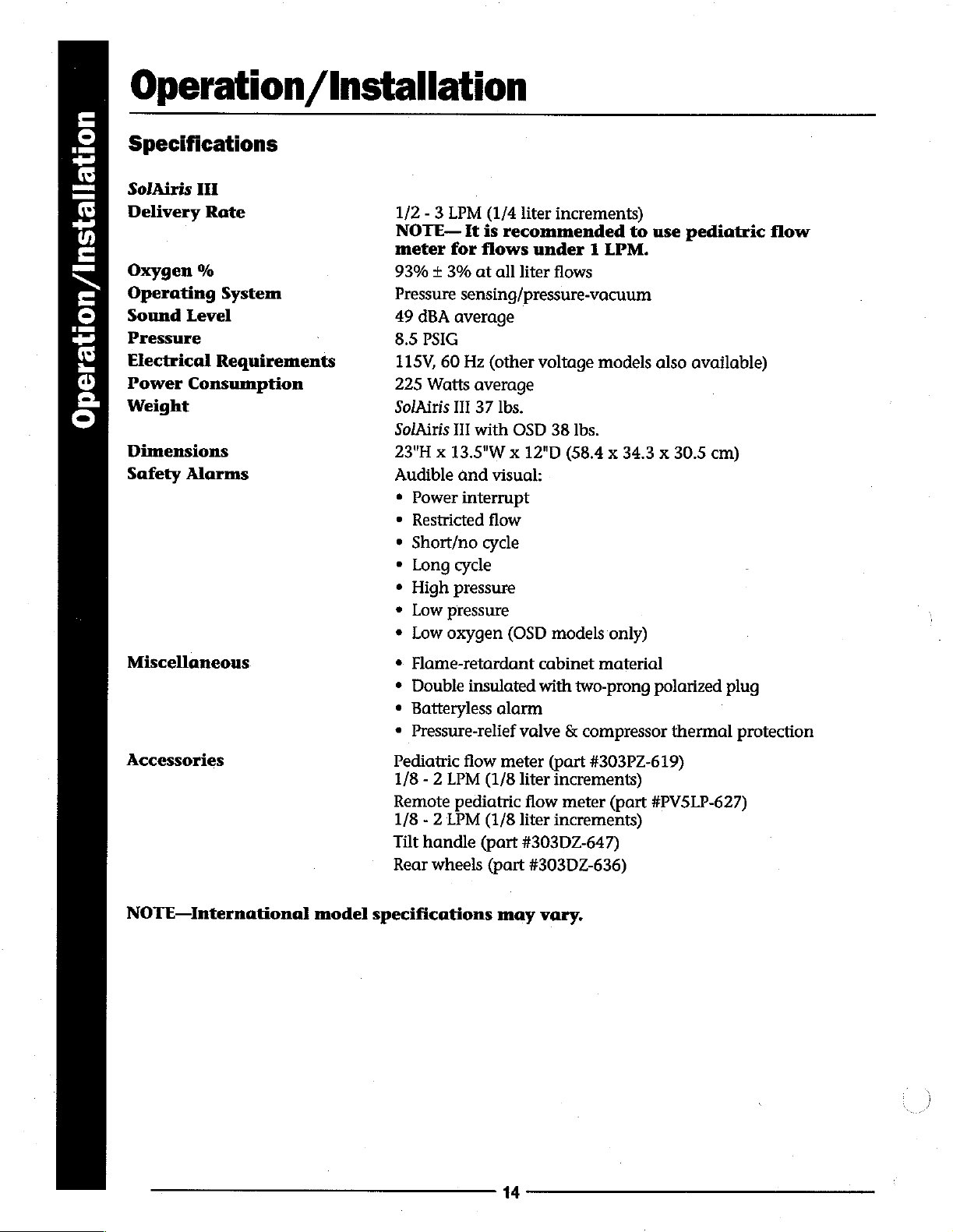
Specifications
S
E:
Y
=
M
=
©
pi
σ
m
Ф
©
©
SolAiris
Delivery
Oxygen
Operating
Sound
Pressure
Electrical
Power
Weight
Dimensions
Safety
IH
Rate
%
Level
Consumption
Alarms
System
Reguirements
1/2 - 3
NOTE—
meter
93% + 3%
Pressure
49
8.5
115V,
225
SolAiris
SolAiris
23"H x 13.5"W x 12"D
Audible
©
©
*
e
*
*
*
LPM
(1/4
It is
for
flows
at
sensing/pressure-vacuum
dBA
average
PSIG
60
Hz
(other
Watts
Power
Restricted
Short/no
Long
High
Low
Low
average
III
37
III
with
and
interrupt
flow
cycle
cycle
pressure
pressure
oxygen
liter
increments)
recommended
under 1 LPM.
all
liter
flows
voltage
lbs.
OSD
38
visual:
(OSD
models
to
use
pediatric
models
lbs.
(58.4 x 34.3 x 30.5
only)
also
available)
flow
cm)
Miscellaneous
Accessories
NOTE—International
model
*
Flame-retardant
*
Double
*
Batteryless
*
Pressure-relief
Pediatric
1/8 - 2
Remote
1/8 - 2
Tilt
Rear
specifications
insulated
flow
LPM
pediatric
LPM
handle
wheels
(1/8
(1/8
(part
(part
cabinet
with
alarm
valve & compressor
meter
may
(part
liter
flow
liter
#303DZ-647)
#303DZ-636)
vary.
material
two-prong
#303PZ-619)
increments)
meter
increments)
(part
polarized
thermal
#PV5LP-627)
plug
]
protection
14
Page 15
Operation
Operating
1.
Remove
in
the
2.
Insert
is
double-insulated
NOTE—The
other.
outlet
the
the
“Off”
the
plug
To
only
SoiAiris
power
position.
reduce
into
plug
one
cord
way.
/Installation
Ill
completely
an
electrical
to
protect
on
the
the
risk
Do
SolAiris
not
from
outlet.
against
concentrator
of
electric
attempt
the
strap.
The
SolAiris
electric
shock.
shock,
to
defeat
this
Make
sure
the
III
has a two-prong
has
one
blade
plug
is
intended
this
safety
power
feature.
switch
polarized
wider
to
is
than
fit
in a wall
plug
the
and
ο
で
ο
-
ad
=.
©
=
に
=
CAUTION—Improper
other
WARNING—
or
concentrator
objects
gas
Press
quired”
tarily.
Only
The
duced
+
*
NOTE—If
mittently.
below
When
quired,
few
electric
when
or
heaters.
the
power
light
The
SolAiris
OSD
by
Normal
Low
Oxygen
82%.)
the
Low
seconds,
Oxygen
near a person
naked
will
“Power”
is
an
optional
the
unit.
Oxygen
the
(On
unit
with
Oxygen,
only
use
of
the
shock
within a minimum
switch
II
(yellow
oxygen
the
hazards.
promotes
receiving
flames.
to
illuminate
light
Concentrators
The
(green
303CS,
the
and
the
“Power”
Do
the
“On”
and
also
illuminates.
device
OSD
operates
light) - oxygen
light) - oxygen
level
falls
this
OSD
is
Normal
and
within
tured
power
Do
not
rapid
oxygen
of
not
use
position.
audible
with
SolAiris
as
follows:
levels
below
signal
"On,”
Oxygen)
“Normal
cord
use the
burning.
therapy.
five
feet
in
rooms
When
signal
levels
will
OSD
concentrators
>85% + 2%
<85% + 2%
75%,
will
sound
all
four
on
the
Oxygen”
and
plugs
unit
Do
from
heated
the
sound
an
audible
if
indicator
front
lights
can
if
the
not
smoke
Do
not
hot,
sparking,
by
unit
is
turned
(the
that
(requires
signal
the
oxygen
lights
panel
will
will
cause a burn,
power
paraffin
patient
monitors
remain
cord
when
operate
on,
the
alert
the
servicing).
will
level
(Power,
briefly
illuminate.
on.
is
damaged.
using
the
oxygen
or
burning
or
portable
“Service
system)
oxygen
sound
falls
Service
fire,
or
this
unit
Re-
momen-
pro-
inter-
Re-
After
a
2
o
=.
©
=
a
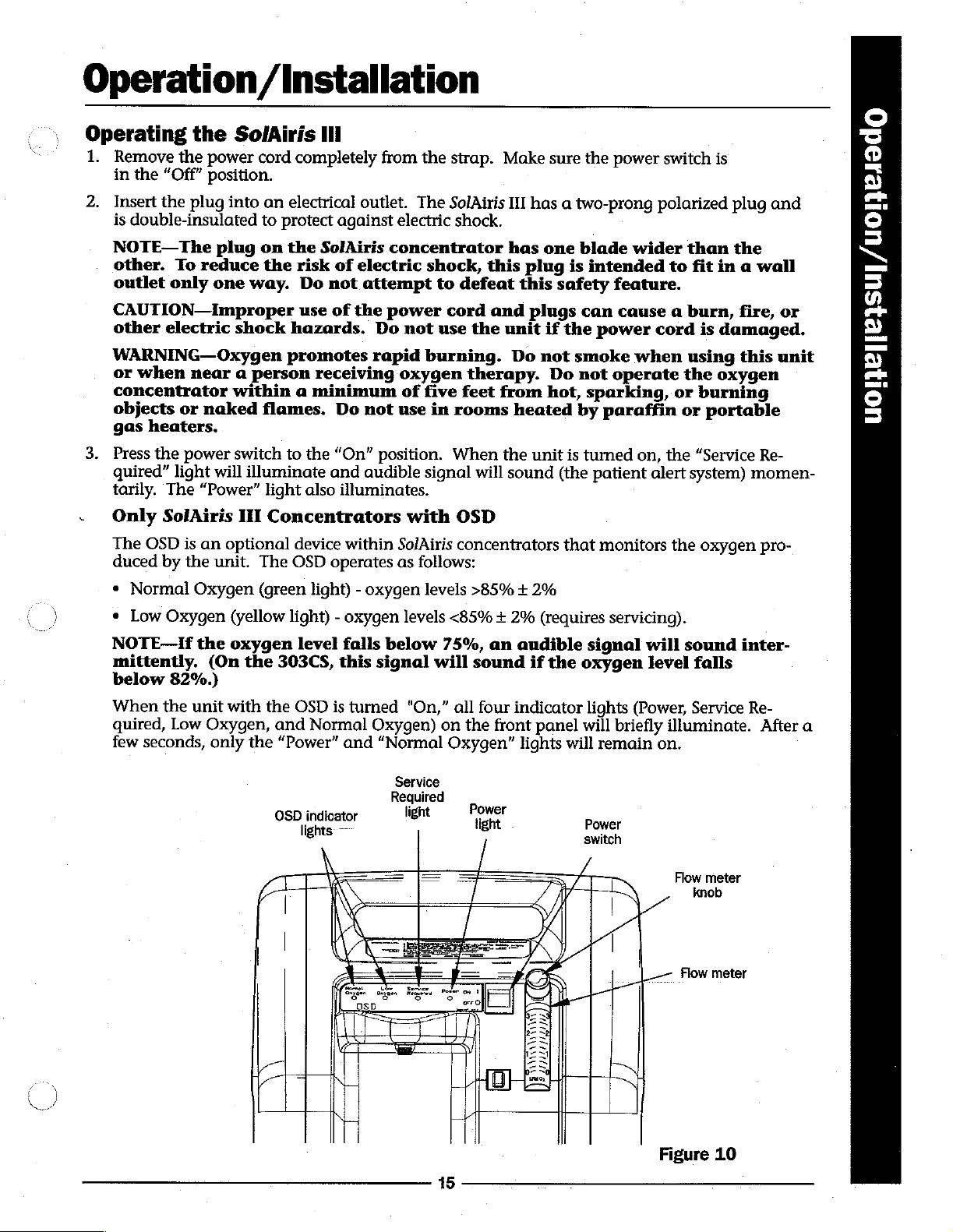
Service
Required
light
s
JE
oe
indi
|
m
15
=
p
‘ower
tight
/
/
Power
switch
B
|
Figure
Flow
knob
Flow
meter
meter
10
Page 16
に
©
ドー
S.
©
pa]
ELA
=
へ
へ
=
©
rar)
©
dm
Ф
©
©
Operation/Installation
For the
illuminated
monitoring
NOTE—If
alarms
switch
Required”
4.
Slowly
the
NOTE—When
eventually
clockwise,
NOTE—If
Restricted
audible
first
fifteen
during
the
oxygen
the
“Service
during
“Off.”
light
turn
the
appropriate
the
will
the
the
flow
Flow
and
visible
minutes
the
oxygen
twice
operation,
Then
flow
flow
remains
meter
rate.
flow
shut
flow
meter
Alarm.
alarm
turn
off
increases.
of
operation,
stabilization
every
Required”
the
unit
the
unit
on,
refer
knob
until
meter
the
is
The
knob
oxygen
turned
unit
may
the
second.
light
will
“On”
to
the
the
flow
is
turned
flow).
to
approximately 0 LPM,
will
be
activated.
green
process.
illuminates
automatically
continue
“Normal
again.
Troubleshooting
meter
clockwise,
When
After
and
If
the
ball
is
the
to
run,
Oxygen”
that
time,
the
shut
“Service
Chart
centered
the
knob
however
light
the
OSD
audible
off.
Turn
on
on
the
flow
decreases
is
turned
it
may
an
will
remain
will
begin
signal
the
power
page
line
intermittent
31.
next
counter-
activate
to
(and
the
NOTE—Use
rates
NOTE—The
and
if
5.
6.
under 1 LPM.
flow
necessary.
The
flow
flow
rate,
a
1/16"
Allen
The
SolAiris
meter
Performing
It
is
suggested
1.
After
removing
If
shipping
1-800-338-1988
2.
Record
3.
Check
4.
Plug
visible
5.
Set
6.
Using
the
the
an
the
to
be
unit
alarms.
flow
oxygen
a
pediatric
unit
rate
to
has a locking
tighten
bit.
III
oxygen
the
Initial
that
an
the
damage
for
number
sure
the
into
an
meter
at 3 LPM
analyzer,
flow
may
require
stabilize.
hex
screw
No
adjustment
concentrator
Inspection
initial
inspection
SolAiris
has
specific
of
extended
HI
occurred,
hours
electrical
and
check
on
meter
The
device.
located
from
instructions.
the
life
outlet,
let
the
(part
up
to
20
flow
rate
If
it
is
on
can
be
made
is
now
is
performed
the
carton,
contact
hour
filter
the
the
meter.
and
turn
unit
concentration
#303PZ-619
minutes
should
necessary
the
hex
without
ready
the
for
upon
examine
DeVilbiss
the
air
filter
unit
run
for
or
*PV5LP-627)
for
the
oxygen
be
monitored
to
preset
nut
just
loosening
use
receiving
it
Shipping/Traffic
are
“On,”
at
least 20
at 3 LPM
below
for
in
and
any
(page
and
the
place.
check
minutes.
concentration
and
lock
in
the
the
control
the
hex
screw.
oxygen
external
19).
concentrator:
damage.
Department
the
audible
for
flow
readjusted
prescribed
knob
using
at
and
7.
Using
SMART
each
sieve
NOTE—If
times
DeVilbiss
are
Track
bed
at 3 LPM.
the
unit
not
within
Service
(OSD
units
fails
to
operate
specification)
Department.
only)
or a stop
properly
or
if
internal
watch,
(i.e.
oxygen
16
check
]
damage
the
cycle
time
concentration
is
found,
(page
21)
or
cycle
contact
for
the
Page 17
Operation
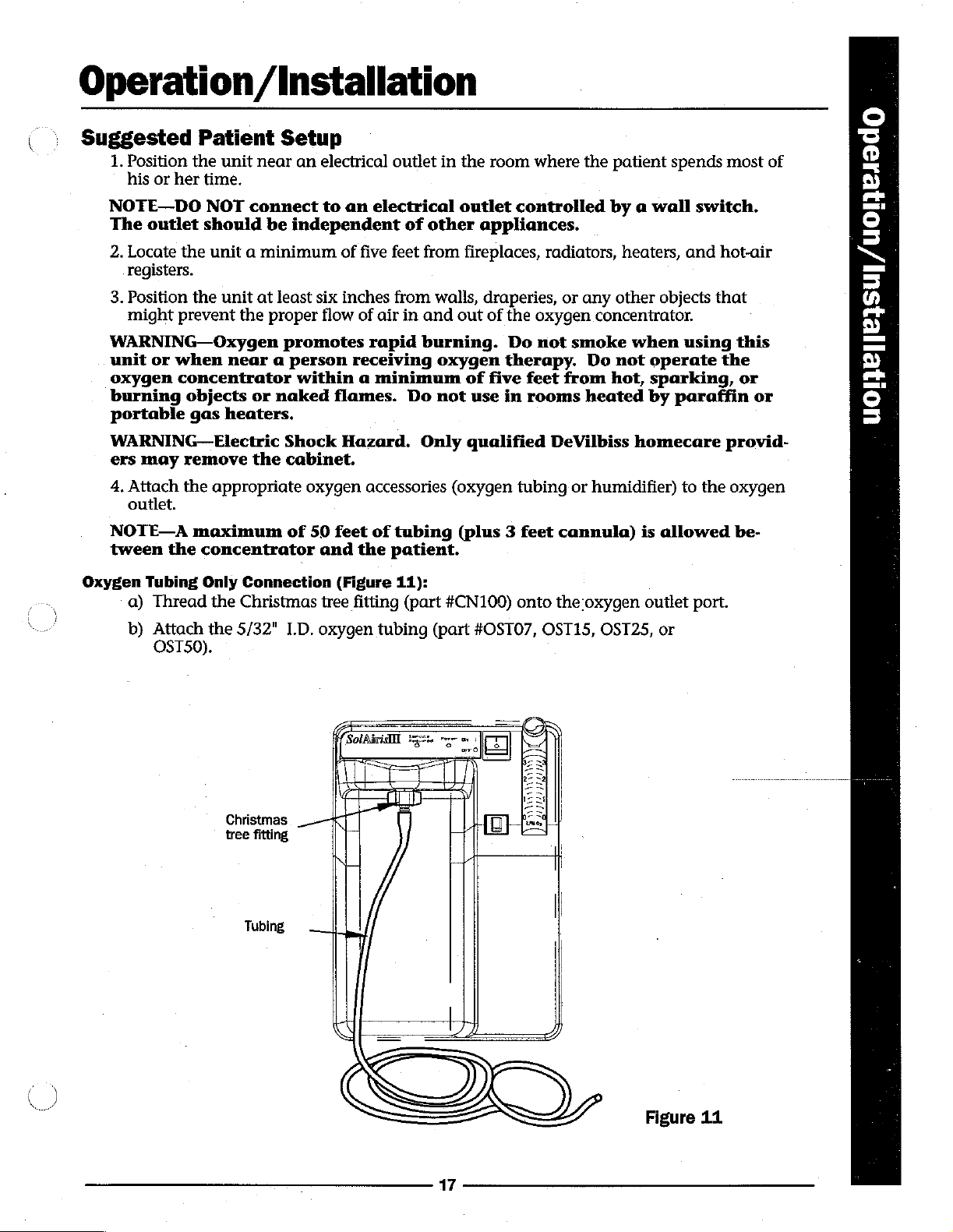
Suggested
1.
Position
his
NOTE—DO
The
outlet
2.
Locate
registers.
3.
Position
might
WARNING—
unit
or
oxygen
burning
portable
WARNING—Electric
ers
may
4.
Attach
outlet.
Patient
the
unit
or
her
time.
NOT
should
the
unit a minimum
the
unit
prevent
Oxygen
when
concentrator
near a person
objects
gas
heaters.
remove
the
appropriate
the
/Installation
Setup
near
an
connect
be
independent
at
least
proper
promotes
within a minimum
or
naked
Shock
the
cabinet.
electrical
to
an
of
six
inches
flow
flames.
Hazard.
oxygen
outlet
electrical
of
five
feet
from
from
of
air
in
and
rapid
receiving
accessories
burning.
Do
Only
in
other
walls,
oxygen
not
(oxygen
the
room
where
outlet
fireplaces,
out
of
qualified DeVilbiss
controlled
appliances.
draperies,
of
the
oxygen
Do
therapy.
five
feet
use
in
rooms
tubing
the
radiators,
or
any
concentrator.
not
smoke
Do
from
heated
or
humidifier)
patient
by a wall
heaters,
other
not
hot,
spends
objects
when
operate
sparking,
by
paraffin
homecare
to
most
switch.
and
hot-air
that
using
the
provid-
the
of
this
or
or
oxygen
ο
3
©
=
W
=
©
=
会
の
l
2
S
=
©
=
в
NOTE—A
tween
Oxygen
Tubing
a)
Thread
b)
Attach
OST50).
maximum
the
concentrator
Only
the
the
Christmas
tree
of
Connection
Christmas
5/32"
I.D.
fitting
Tubing
50
feet
of
tubing
and
the
patient.
(Figure
tree
oxygen
Γι
一
-|
11):
fitting
(part
tubing
(part
(plus 3 feet
#CN100)
onto
#OSTO7,
cannula)
the
oxygen
OST15,
9
ん
na
MU
мм
41111111811
En
T
8
D
is
outlet
OST25,
allowed
port.
or
be-
Figure
17
11
Page 18
<
©
ビー
S
K
Pas
の
=
N
=
©
—
©
um
©
Qi
©
Operation
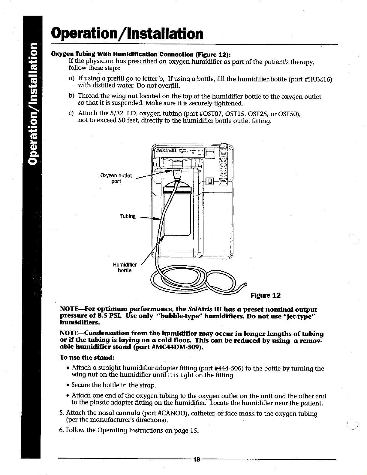
Oxygen
Tubing
If
the
physician
follow
a)
If
using
with
b)
Thread
that
so
c)
Attach
not
With
steps:
these
a
prefill
distilled
the
wing
suspended.
is
it
the
5/32
to
exceed
Oxygen
port
Humidification
has
water.
50
/Installation
prescribed
go
to
Do
nut
located
I.D.
oxygen
feet,
outlet
Connection
an
letter
b,
not
overfill.
on
sure
Make
tubing
directly
to
oxygen
If
using
the
the
(Figure
humidifier
a
bottle,
top
of
the
securely
is
it
(part
#OST07,
humidifier
12):
as
part
fill
the
humidifier.
humidifier
tightened.
OST15,
bottle
outlet
of
the
bottle
OST25,
fitting.
patient's
bottle
to
the
or
(part
oxygen
OST50),
therapy,
#HUM16)
outlet
NOTE—For
pressure
humidifiers.
NOTE—Condensation
or
if
the
able
humidifier
To
use
*
Attach a straight
wing
Secure
of
tubing
the
nut
the
optimum
8.5
PSI.
is
stand:
on
the
bottle
stand
Tubing
Humidifier
bottle
performance,
Use
only
from
laying
(part
humidifier
humidifier
in
the
“bubble-type”
the
humidifier
on a cold
#MC44DM-509).
adapter
until
it
strap.
the
SolAiris
floor.
fitting
is
tight
III
humidifiers.
may
occur
This
can
(part
#444-506)
on
the
fitting.
Figure
has a preset
Do
not
in
longer
be
reduced
to
the
12
nominal
use
lengths
by
using a remov-
bottle
output
“jet-type”
of
by
turning
tubing
the
*
Attach
to
5.
Attach
(per
6.
Follow
one
end
the
plastic
the
the
manufacturer's
the
adapter
nasal
Operating
of
the
oxygen
fitting
cannula
directions).
Instructions
on
(part
tubing
#CANOO),
to
the
humidifier.
on
page
the
oxygen
Locate
catheter,
15.
18
outlet
the
or
face
on
the
unit
humidifier
mask
to
the
and
the
near
the
oxygen
other
end
patient.
tubing
Page 19
Maintenance
|
Routine
The
oxygen
Oxygen
The
patient
supplied
Patient
Humidifier
by
followed:
1.
Wash
2.
Soak
the
minutes.
3.
Rinse
Cannula/Mask
The
patient
Air
Filter
The
air
filter
steps
should
1.
Remove
2.
Wash
3.
Rinse
before
WARNING—Do
filter
is
NOTE—The
abnormal
NOTE—Operation
without
filter
and
Maintenance
patient
should
the
the
thoroughly
should
should
be
the
thoroughly
reinstalling.
still
the
should
(reusable
clean
the
manufacturer.
humidifier
humidifier
This
solution
with
and
Tubing
clean
and
be
cleaned
followed:
the
air
filter,
air
filter in a solution
with
not
attempt
damp.
air
filter
amounts
of
air
filter
cause a decrease
perform
bottles
the
only)
humidifier
If
no
cleaning
bottle
in a solution
in a solution
acts
as a germicidal
hot
tap
water
replace
located
warm
should
of
dust,
the
will
the
at
least
once a week
on
the
of
tap
water
to
operate
be
monitored
lint,
SolAiris
prematurely
in
the
following
bottle
daily.
instructions
of
of
one
part
and
refill
cannula
back
of
warm
water
and
the
and
power.
III
concentrator
occlude
unit
performance.
maintenance.
The
patient
were
hot
water
white
and
vinegar
agent.
with
distilled
and
tubing
by
the
patient.
the
unit.
and
dishwashing
towel
dry.
The
unit
without
more
closely
in
the
should
supplied,
dishwashing
to
three parts
water
for
as
instructed
To
clean
detergent.
filter
should
the
air
in
environments
extreme
extended
follow
these
the
instructions
steps
should
detergent.
hot
water
use.
Do
not
by
the
manufacturer.
the
air
filter
be
completely
filter
or
environments
life
intake
be
for
30-45
overfill.
these
dry
while
the
with
or
bacteria
te
Pettey
Exterior
Cabinet
The patient
mild
household
WARNING--Do
based
solvents
Periodic
Every
SolAiris
continued
by
the
unit
SolAiris
A.
trouble-free
homecare
will
void
III
Check
non-OSD
To
verify
1.
Calibrate
lyzer
NOTE—Changes
oxygen
conditions
should
clean
cleaner
not
or
Homecare
III
oxygen
provider
the
warranty.
Recommended
oxygen
concentration*
models
the
oxygen
the
should
concentration
to
the
concentrator
and
wipe
it
apply
cleaning
liquid
agents.
Provider
concentrator
performance,
during
and
oxygen
be
properly
in
the
location
periodic
Preventative
once a year
concentration:
analyzer
calibrated
temperature,
reading.
exterior
dry.
directly
Preventative
is
thoroughly
the
following
oxygen
Maintenance
with an
of
oxygen
for
OSD
prior
to
using
altitude,
The
the
concentrator.
cabinet
to
the
cabinet
tested
preventative
patient
analyzer
models.
checking
the
manufacturer's
or
analyzer
19
by
using a damp
or
utilize
Maintenance
and
burned-in
maintenance
visits.
humidity
Failure
(PM)
(part
the
oxygen
should
#O2ANA) - every 3 months
concentration.
may
be
calibrated
cloth
or
any
petroleum-
at
the
factory.
should
to
properly
recommended
affect
the
in
sponge
be
with
To
assure
performed
maintain
The
ana-
procedure.
analyzer's
similar
a
the
for
Page 20

=
=
=
©
©
=
=
©
G
Maintenance
2.
The
concentrator
oxygen
3.
Connect
4.
Record
B.
Check
turned
lights
C.
Change
To
change
1.
Open
2.
Pull
3.
Place
4.
Securely
NOTE—If
may
be
*
Round
Rectangular
AND
*
Intake
D.
Change
concentration.
the
analyzer
the
reading.
the
audible
“On,”
are
operating.
Extended
the
the
extended
the
current
insert
the
DeVilbiss
substituted.
Felt
Pre-Filter
Bacteria
Final
alarm
listen
Life
the
filter:
filter
door.
the
Felt
Pre-Filter
Filter
Bacteria
must
9
for
the
Intake
life
date
new
Extended
Note
(part
(part
Filter
operate
to
the
unit's
and
indicator
audible
Bacteria
filter
out
and
hours
extended
the
different
#444-503)
(part
#444-504)
(part
for
a
minimum
oxygen
lights
alarm
from
Life
#MC44D-722)
-
#PVSLD-651)
and
Filter
the
rubber
of
operation
life
filter
Intake
PM
-
change
-
change
of
20
outlet
(part
port
-
once
check
#MC44D-605)
grommet
on
the
into
the
Filter
schedules.
once
a
-
change
every
-
every
minutes
and
a
year.
to
see
if
label
grommet
is
not
month
every
six
months
two
years.
before
wait
until
When
(Figure
the
front
-
of
a
and
used,
OR
three
the
once
new
checking
the
power
panel
a
year.
13)
and
extended
close
the
the
following
months
the
display
switch
indicator
discard.
life
filter
stabilizes.
is
filter.
door.
filters
Bib
screw
Grommet
Rear
cover
Filter
door
Air
filter
Extended
life
intake
bacteria
filter
20
Figure
13
Page 21

Maintenance
To
1.
Unplug
2.
Remove
Flow
change
meter
the
the
the
final
unit
hose
bacteria
and
remove
from
each
filter:
the
end
of
cabinet
the
filter
Bib
oe
Spring
(see
(Figure
ol
clip
page
34).
14).
>
=
©
=
일
am
še
©
3.
Discard
4.
Install
E.
Recommended
hours
Track
for
normal
NOTE—Increases
decreases
various
Sea
2500
5000
F.
Change
To
change
1.
Remove
2.
Install
G.
Change
(whichever
the
the
of
operation
or a stop
cycle
in
the
altitudes
Level - approximately 8 seconds
feet - approximately
feet - approximately
Exhaust
the
tubing
Compressor
comes
filter.
new
final
Compressor
(whichever
watch)
times)
in
altitude
two
variables
are
Silencer - when
the
exhaust
hose
clamps
on
the
HEPA
first).
filter
and
if
with
as
follows:
new
Cycle
silencer
with “IN”
Time
Check - prior
comes
longer
no
and
and
silencer,
Filter - every
first).
than
leaks,
flow
will
10
11
the
(Figure
tubing
inspect
slightly
seconds
seconds
compressor
and
Final
bacteria
fitting
normal
from
Monitor
and
rate
secure
five
years
toward
will
at 3 LPM
at 3 LPM
at 3 LPM
33):
the
filter
flow
to
or
the
unit
cycle
times
change
slightly
decrease
is
rebuilt
exhaust
with hose
or
25,000
meter.
at
three
years
cycle
exist
(refer
internal
cycle
or
silencer.
components
increase
times.
replaced.
clamps.
hours
times
to
of
operation
Figure
or
12,000
(using
page
cycle
Cycle
14
SMART
27
as
needed.
times
times
and
at
To
replace
1.
Unplug
2.
Loosen
3.
Using a wrench,
4.
Discard
the
the
hose
the
compressor
unit
and
clamp
unscrew
HEPA
filter.
remove
and
remove
HEPA
the
only
the
HEPA
filter:
the
rear
hose
filter
21
cabinet
from
from
the
(refer
the
outlet
compressor
to
page
fitting
head.
34).
end
of
the
HEPA
filter.
Page 22

Maintenance
NOTE—Teflon
prior
5.
NOTE—Make
6.
Maintenance
7,
*
environment.
concentrator
frequency
which
Between
to
installation
Install
until
the
tight.
Attach
Leak
test
to
fittings
The
Preventative
(not
takes
Patient
A.
Discard
filter
B.
Wash
C.
Check
extended
must
the
the
and
operating
into
(if
or
oxygen
be
tape
or
of
new
HEPA
filter
sure
the
hose
to
the
HEPA
filter
connections
Maintenance
The
homecare
environment
to
exceed
three
consideration
Maintenance
oxygen
using
replace
tubing,
these
the
concentration.
life
intake
changed
annually).
LOX-8
HEPA
by
using
filter
outlet
end
fitting
fittings.
with
the
Schedule
provider
months
the
cannula,
filters
instead
air
filter.
bacteria
paste
should
filter.
a
wrench
marked
end
Apply
unit
running.
is
responsible
and
on
specific
humidifier
of
If
the
filter
does
be
applied
to
attach
“IN”
of
the
filter
the
leak
test
If
an
stated
above
for
determining
non-OSD
models
operating
bottle,
the
extended
unit
falls
within
not
need
to
the
the
filter
is
toward
and
solution
air
leak
reflects
compressor.
secure
(such
is
present,
a
normal,
with
determining
a
preventative
or
one
environment.
intake
life
to
be
bacteria
intake
93%
+
replaced
compressor
to
the
compressor
hose
as
Epi-Seal®
the
clean
the
condition
maintenance
year
on
filter
bacteria
3%
at
3
between
fitting
clamp.
LEAK-SEEK®)
solution
will
operating
of
OSD
models)
and
filter).
LPM,
the
patients
head
bubble.
the
interval
felt
pre-
(but
Epi-Seal®
LEAK-SEEK®
is
a
registered
trademark
of
Bonded
Products,
22
Inc.
Page 23

Patient
Patient
The
SolAiris
situations.
a
malfunction
The
diagnostic
malfunction.
The
visible
is
internally
audible
e
e
»
*
e
*
e
The
visible
tion.
After
few
seconds.
NOTE—Hf
run several
Alert
III
patient
This
system
should
lights
alarm
powered;
alarm
low/high
minimum/maximum
valve
bed
compressor
restricted
power
If
the
that
sounds,
pressure
failure
failure
flow
fail
(blinking
and
audible
unit
is
time,
the
the
minutes
Alert
System
alert
system
is
comprised
occur.
on
the
PC
located
failure
turned
concentrator
on
no
batteries
other
cycle
(blinking
visible
alarms
“On”
alarm
will
before
the
than
&
will
of
board
front
are
during
visible
produce
alarm
alarm and
will
activate
and
not
has
the
Diagnostic
detect
both
will
panel
required.
an
been
power
unit
visible
help
reads
unit
start-up, a problem
and
pulsing
for
plugged
audible
unused
component
and
audible
service
When
pulsing
approximately
fail
personnel
"Service
the
audible
in,
no
alarm
pulse
for
alarm
Required.”
indicator
audible
alarm)
and
the
an
will
failure
20
will
extended
System
as
well
as
alarms
diagnose
alarm)
visible
activate.
which
The
lights
has
occurred
minutes
sound
for
alarm
period,
signal
the
cause
audible
illuminate
such
in a no
the
will
restricted
alarm
power
first
blink
the
flow
the
patient
of
the
system
or
the
as:
situa-
10
seconds.
every
unit
must
if
IU
W
=
®
=
eb
>
©
=
=
Ro
に
トリ
ge.
=
©
の
=
o
の
by
の
=
©
3
The
printed
well
as
the
transducer
pressure
within
Most
to
the
or
the
major
unit.
circuit
alarms
indicates a malfunction,
component
preset
malfunctions
(PC)
board
by
using a pressure
failure.
minimum
and
will
is
responsible
Alarms
maximum
shut
the
for
transducer.
the
patient
will
also
cycle
unit
off
monitoring
When
alert
system
be
activated
times.
automatically,
and
the
pressure
will
if
The
alarm
preventing
controlling
sensed
activate
the
system
system
the
entire
by
the
regardless
fails
cannot
any
if
to
operate
be
further
system
pressure
it
overridden.
damage
is
as
a
23
Page 24

Е
©
цы
の
Ed
の )
о
ドー
の
©
トー
0
©
à
3
~
da
E
x
0
=
ko
=)
G
в.
Patient
Diagnostic
The
PC
board
unit
will
shut
should
page
be
43)
Oxyger
(OSD
System
has
off,
used
as
because
sensor
assembly
units
only)
and
there
Alert
three
red
these
a
troubleshooting
may
&
diagnostic
lights
be
more
PC
board
Diagnostic
lights
will
illuminate
aid
than
(Figure
in
conjunction
one
Diagnostic
(on
back
of
15).
in
a
reason
lights
PC
board)
particular
for
System
Should
with
the
a
malfunction.
a
unit
malfunction
sequence.
pressure-vacuum
The
diagnostic
occur,
gauges
the
lights
(refer
to
"4-way"
indicator
light
Figure
15
24
Page 25

Patient
Alert
&
Diagnostic
System
"|
The
diagnostic
This
gives
the
been
turned
view
To
unit:
the
1.
Turn
2.
Open
3.
Use
release
vertical
the
WARNING—Electric
when
uct
off.
the
the
the
the
light
pressing
damage.
system
service
light
unit
air filter
plastic
the
diagnostic
sequence
will
technician
sequence
“On.”
error
Memory
the
also
keep
corresponding
door.
indicator
Switch
light
access
for
the
last
Shock
memory
the
last
the
ability
tool
(part
“S”
through
holes (located
failure
Hazard.
switch;
Pediatric
bleed
diagnostic
to
view
the
the
to
#303DZ-635)
the
single
on
mode
(unless
Do
not
doing
flow
so
meter
off
light
cause
unit
access
the
PC
the
use
metal
may
Memory
access
failure
of a unit
malfunction
or
memory
cause
switch
hole
sequence
other
non-metallic
hole
located
board).
or
other
personal
Diagnostic
access
shutdown
The
has
holes
in
without
to
the
PC
board
been
conductive
injury
light
memory.
after the
opening
`
tool
to
left
of
will
cleared).
and
unit
has
press
and
the
three
display
tools
prod-
W
=
©
=
ee
2
©
=
[asi
名
2
o
ga
=
©
n
=
o
の
<
DI
©
3
ペー
=
св
=
ca
co
=
E
=
Figure
25
16
Page 26

E
©
Y
m
Y
К
Patient
After
To
viewing
clear
1.
Unplug
into
2.
Plug
the
、
the
diagnostic
unit
the
wall
unit
back
Alert
light
seguence,
light
while
still
outlet
into
running.
until
the
&
the
memory:
the
wall
Diagnostic
memory
Do
first
alarm
outlet.
may
not
sounds
This
be
turn
the
process
cleared
unit
(approximately
will
System
for
future
“Off.”
reset
Do
not
10
diagnostic
assistance.
plug
the
unit
seconds).
light
memory.
back
©
©
=
OD
AU
o
9
~
=
や
<
Li
=
o
ドー
©
o.
Shown
their
test
observed
switch
below
respective
points.
x
x
O
|
x
O
|
O
|
о
x
O
|
o
o
O
|
NOTE—These
(Refer
HIGH
POSSIBLE
4-WAY
(VOLTAGE
LONG
POSSIBLE
LEAK,
(VOLTAGE
SHORT
POSSIBLE
SIEVE
(VOLTAGE
PC
BOARD
POSSIBLE
WIRE
ELECTRONIC
when
“S”
are
the
meanings.
to
PRESSURE
VALVE,
CYCLE
CAUSE:
WORN
CYCLE
BEDS
CAUSE:
HARNESS,
alarms
while
failure
Normal
CAUSE:
TO
combinations
It
is
extremely
Operating
A
PC
BOARD
4-WAY)
A
COMPRESSOR
To
4-way)
A
CAUSE:
TO
4-WAY)
FAILURE
DEFECTIVE
COMPONENT.
will
unit
it
turned
unit
is
ranning.
IMPORTANT
for
beneficial
Sequence
illuminate
off
and
the
diagnostic
to
attach
on
page
27).
x
x
Ж
|
x
O
|
№
|
ο
x
x
o
x
O
|
when
on
unit
again
shuts
by
service
pressure
HIGH
POSSIBLE
AS
VOLTAGE)
LONG
POSSIBLE
AS'A
VOLTAGE)
SHORT
POSSIBLE
AS
VOLTAGE)
AN
DURING
POSSIBLE
CROSS
depressing
lights(top
gauges
PRESSURE
CAUSE:
'A'
(NO
CYCLE
CAUSE:
(NO
CYCLE
CAUSE:
'A'
(NO
UNEVEN
OPERATION
CAUSE:
PORT
off
and
to
to
SAME
4-WAY
SAME
4-WAY
SAME
4-WAY
CYCLE
LEAK,
VALVE
can
be
and
releasing
bottom)
the
sieve
TIME
LEAKAGE
and
bed
When
continue
control
a
system
to
run.
panel
NOTE—The
when
be
not
the
pressurizing.
considered
error
is
The
will
illuminate.
green
four-way
an
sensed,
audible
“4-way”
valve
When
alarm
alarm
it
the
compressor
will
indicator
is
activated.
is
off,
the
indicator.
also
right
will
automatically
sound
light
At
26
and
on
the
bed
the
"Service
the
PC
same
should
shut
off,
Required”
board
time
be
will
the
pressurizing.
but
the
light
illuminate
left
sieve
cooling
on
the
only
bed
should
This
light
fan
will
is
Ne
Page 27

Troubleshooting
Normal
NOTE—Most
and
When
attaching
1.
2.
3.
NOTE—Increases
decreases
various
Operating
types
possibly a change
the
concentrator
the
pressure-vacuum
Left
sieve
bed
will
drawn
a)
Right
drawn
a)
(approximately
Four-way
1)
Approximately
green
sieve
(approximately
Four-way
1)
There
the
Step 1 is
in
altitudes
valve
“4-way”
bed
will
valve
is
no
PC
board
repeated
the
Sequence
of
unit
in
is
turned
gauges
pressurize
11
is
shifted.
12
VDC
indicator
pressurize
11
is
in
the
12
VDC
is
not
illuminated.
again.
in
altitude
two
variables
are
as
follows:
malfunctions
cycle
“On,”
(approximately
in.
Hg).
is
light
(approximately
in.
Hg).
rest
signal
and
of
the
times
this
to
supplied
position.
at
will
or a unit
normal
the
sieve
is
illuminated
the
four-way
flow
rate
slightly
SoiAiris
will
cause a deviation
shutdown.
cycling
bed
test
15
PSI)
from
PC
board
on
15
PSI)
and
will
decrease
III
Series
sequence
points
and
the
slightly
the
and
located
right
to
the
PC
left
green
cycle
should
at
bed
will
four-way
board.
sieve
bed
“4-way”
increase
times.
in
this
sequence
be
observed
the
top
of
the
have a vacuum
and
the
will
have a vacuum
indicator
cycle
Cycle
times
times
by
unit.
light
and
at
on
|
=
©
トー
=
©
wn
Pz
©
©
=
E]
de,
*
Sea
Level - approximately 8 seconds
*
2500
feet - approximately
*
5000
feet - approximately
Simplified
key
The
effective
solutions
Type
I-Unit
Approach-Connect
proper
components
Type
fan
Approach-Check
cycling
Il-Power
runs,
«
If
WARNING—Mechanical
working
*
If
Troubleshooting
simple
to
approach
follows:
as
are
runs
for a while
sequence.
(i.e.
if
switch
but
compressor
voltage
voltage
is
on
is
troubleshooting
problem.
solving
to
the
the
right
is
the
compressor
present,
compressor.
not
the
and
shuts
pressure-vacuum
something
If
bed
pressurizes
in
the
“On”
will
not
start.
voltage
then a defective
Hazard.
present,
then a defective
10
seconds
11
seconds
recognize
to
is
off.
in
position
at 3 LPM
different
The
gauges
sequence
the
first,
and
(115
VAC)
capacitor
Keep
wire
at 3 LPM
at 3 LPM
of
which
to
troubleshoot
fingers,
type
types
the
sieve
incorrect,
is
“Power”
(Figure
or
compressor
harness
bed
indicator
32).
loose
or
problem
problems
of
test
points
troubleshoot
the
four-way
light
exists.
clothing,
PC
board
and
exists
the
and
]
and
valve).
is
illuminated,
etc.
exists.
select
approaches
look
for
appropriate
the
away
when
most
the
the
cooling
for
27
Page 28

‘on
=
e
o
©
=
の
2
K
=
©
de
=
Troubleshooting
Type
IM-The
Approach-Check
*
If
/
*
If
¥
Y”
/
/¥
NOTE—Check
solution
present,
the
+
If
Y
unit
is
operating
cycle
cycle
times
are
times
leaks
to
all
the
solution
back
times
sieve
are
filters
compressor
for
fittings
in
are
sieve
defective
cycle
occluded
system
defective
malfunctioning
unit
cycle
topofthe
times.
shorter
beds
longer
or
leaks
service.
normal,
than
or
or
sieve
and
will
beds
and
continues
than
normal,
normal,
‘bed
check
using
a
hose
“bubble-up.”
check
to
check
check
valves
certified
connections
for
an
oxygen
cycle,
for:
for:
leak
All
leaks
leak:
but
has
low
detection
with
unit
should
oxygen
solution.
running.
be
concentration.
repaired
Apply
If
an
before
leak
air
test
leak
putting
is
accumulator
¥
pressure
V
flow
/
final
v
outlet
/
+
If
cycle
gauges
¥
Ifvacuum
regulator
meter
bacteria
port
times
are
look
and
reading
tank
filter
normal
proper
for
is
and
vacuum
low,
no
oxygen
the
compressor
leaks
levels.
exist,
may
then
be
defective.
connect
the
pressure-vacuum
Page 29

Troubleshooting
Pulsating
2.
Excessive
or
vibration.
Fluctuating
flow.
4
Little
flow.
5.
Low
tration
increase
6.
Low
tration
in
cycle
air
noise
or
no
oxygen
and
in
oxygen
and
time.
nojse. | 1.
2.
and/|
oxygen | 1.
2.
3.
4.
5.
6.
7.
8.
9.
10.
11.
oxygen | 1.
2.
3.
4.
concen- | 1.
possible | 2.
cycle
time. | 3.
4.
5.
6.
concen- | 1.
decrease | 2.
Intake
defective.
Compressor
nected.
1.
2.
3.
Flow
Hose
Oxygen
blocked.
Occluded
Occluded
Leak
Defective
Defective
Defective
Four-way
Contaminated
Compressor
(broken
check
occluded).
filter
Defective
Defective
Defective
Occluded
Use
of
improper
Occluded
Occluded
and
tubing.
Use
of
excessive
Defective
Leak
in
system.
Defective
Defective
Defective
Pressure
properly
regulator
meter
disconnected
delivery
filters.
in
system.
sieve
compressor
compressor.
valve
reed
valve
or
compressor.
cooling
flow
compressor
sieve
or
humidifier.
vacuum
not
in
place
intake
hose
loose
motor
fan.
humidifier.
humidifier.
filters.
or
defective
meter.
compressor.
defective.
not
adjusted properly
tubing
bed
not
sieve
valve
or
exhaust
tubing.
reed
bed
check
not
to
flow
is
check
reed
fully
beds.
head
defective
cannula
problem
or
discon-
mounts.
valve.
valve.
adjusted
meter.
kinked
or
valve.
valve.
shifted.
dump
silencer
1.
Check
filter
and
2.
Reconnect
1.
Replace
2.
Replace
3.
Replace
1.
Clean
2.
Use
only a bubble-type
3.
Clean
4.
Detach
delivery
attained,
other
straighten
tubing
5.
The
unit
on
50
cannula
(4
mm)
Smaller
addition
may
flow
6.
Replace
7.
Check
8.
Replace
9,
Replace
10.
Replace
11.
Adjust
1.
Adjust
2.
Reconnect
3.
Straighten
4.
Clean
1.
Clean
2.
Check
3.
Replace
4,
Replace
5.
Replace
6.
Clean
1.
Replace
2.
Check
dump
replace
hose.
or
tighten
compressor.
cooling
or
replace
or
replace
cannula
tubing.
check tubing
obstructions.
as
required
if
necessary.
is
designed
feet
(15
meters)
of
approximately
inside
diameter
diameter
of
any
prevent
rate.
or
or
or
obtaining
flow
meter.
all
hoses
compressor.
compressor
check
valve.
or
replace
flow
meter.
hose.
tubing
replace
replace
all
hoses
and
check
valve.
compressor
compressor.
replace
sieve
beds.
vacuum
check
head
valve,
if
necessary.
motor
mounts.
fan.
humidifier.
humidifier.
filters.
from
oxygen
If
proper
for
Clean
or
replace
to
deliver 3 LPM
and 3 feet
tubing.
tubing
other
and
pressure
or
humidifier.
filters.
four-way
or
flow
the
fittings.
reed valve.
remove
fittings.
reed
valve.
reed
exhaust
flow
is
not
kinks
or
or
of
5/32"
the
restriction
desired
regulator.
obstruction.
valve.
valve,
silencer.
=
=
ら
=
2
の
の
>
©
©
=.
=
ga
Page 30

où
=
に
©
©
=
Y
2
2
=
©
~
=
Troubleshooting
Audible
sound
not
is
turned
during
NOTE-If
concentrator
been
extended
the
unit
several
before
fail
alarm
activate.
2.|
"Service
light
illuminate
unit
is
OFF
alarm
when
on
power
the
unused
period,
must
minutes
the
Required”
does
not
when
turned
does
unit
or
failure.
has
for
an
run
power
will
on.
1.
Unit
extended
2.
Defective
3.
Defective
4.
Defective
1.
Defective
2.
Defective
has
OFF
not
period
PC
power
wire
PC
light
Symptom
been
used
of
board.
switch.
harness.
board.
panel.
Symptom
for
time.
an
ON
1.
Allow
and
retry.
2.
Replace
3.
Replace
4,
Replace
1.
Replace
2.
Replace
unit
PC
power
wire
PC
light
to
run
board.
switch.
harness.
board.
panel.
for
20
minutes
1.|
No
1.|
Fan
indicator
illuminated
board.
2.|
Fan
oxygen
flow.
Blinking
operating,
off.
no
lights
on
PC
1.
Severe
a.
Crimped
b.
Occluded
c.
Flow
1.
Blow
fuse
2.
Defective
1,
Line
cord
defective.
2.
Oxygen
breaker
3.
No
power
4.
Line
cord
inside
5.
Defective
6.
Defective
Pulsing
restriction
meter
Pulsing
PC
not
concentrator
activated.
quick-connect
unit
power
circuit
of
tubing.
humidifier.
turned
on
PC
board.
board.
properly
at
receptacle.
is
disconnected.
switch.
breaker.
flow
due
off or
installed
circuit
terminal
to:
set
too
or
ON
la.
low.
OFF
1.
2.
la.
b.
2.
3a.
b.
4,
5.
6.
Straighten
b.
Clean
or
c.
Adjust
flow
Replace
Replace
Insert
Replace
Press
button.
again,
Check
fuse,
checked
Circuit
other
receptacle
Reconnect
Replace
Replace
fuse.
PC
plug
line
the
If
check
building
or
have
by
may
appliances
power
unit
ON
tubing.
replace
board.
in
unit
unit
qualified
may
quick-connect
humidifier.
meter.
OFF
receptacle.
cord.
circuit
breaker
circuit
breaker
internal
house
be
be
switch.
circuit
wiring.
circuit
breaker
wiring
electrician.
fully
loaded
and
another
required.
breaker.
reset
opens
or
with
terminal.
Page 31

Troubleshooting
Fan
operating.
Unit
warm
to
the
touch
and
cannot
restarted
minutes.
3.
Fan
middle
and
tic
on
Fan
4.
or
diagnostic
illuminated
board.
5.
Fan
and
three
lights
on
Fluctuating
or
for
operating,
or
middle
bottom
lights
PC
operating,
top
operating,
middle
PC
no
diagnos- | 2,
illuminated
board.
and
bottom
lights
or
diagnostic
illuminated
board.
flow.
several
top
on
top
all
1.
Compressor
defective.
2.
PC
Defective
3.
Defective
4.
Defective
1.
Compressor
be]
a.
b.
c.
2.
Defective
3.
Defective
1.
Four-way
properly.
Contaminated
1.
Maximum
due
a.
b.
c.
d.
1.
Four-way
2.
Defective
System
1.
a.
b.
c.
Four-way
Occluded
Restricted
passage.
Low
Four-way
Leak
Defective
Defective
Leak
Defective
capacitor.
PC
compressor.
or
high
cooling
compressor.
valve
cycle
to:
in
system,
valve
PC
pressure
in
system.
valve
connector
board.
overheated
filters.
input
valve
compressor
compressor.
board.
compressor.
or
output
line
voltage.
fan.
failed
sieve
beds.
time
was
not
not
shifting.
below
not
fully
Symptom
disconnected/
due
to:
air
to
shift
exceeded
fully
shifted.
reed
valve.
to:
due
9
PSI
shifted.
1.
Reconnect/replace.
2.
Replace
3.
Replace
4.
Replace
la.
Clean
b.
Remove
c.
Check
circuit
appliances.
2.
Replace
3.
Replace
1.
Refer
shoot
2.
Refer
shoot
la.
Clean
b.
Check
c.
Replace
d.
Replace
1.
Refer
shoot
2.
Replace
Check
la.
|
b.
Replace
c.
Clean
NOTE—When
time
diagnostic
nect
operating
NOTE--Refer
explanations
diagnostic
capacitor.
PC
board.
compressor.
or
replace
obstruction.
line
voltage,
independent
cooling
compressor.
to
page
Four-Way
to
page
Sieve
Beds.
or
replace
all
hoses
compressor
compressor.
to
page
Four-Way
PC
board.
hoses
all
compressor.
or
replace
and
stops
lights
gauges
and
sequence.
to
lights
filters.
fan.
51
on
Valve.
43
on
four-way
and
51
on
Valve.
and
four-way
unit
runs
and
illuminate,
look
page
of
the
and
use
alternate
of
other
How
to
How
to
fittings.
reed
valve.
How
to
fittings.
for a short
any
of
for
proper
26
for
various
alarms.
Trouble-
Trouble-
valve.
Trouble-
valve.
the
red
con-
=
-
©
=
=
©
n
=
©.
©
=.
=
go.
BLINKING
1.
Fan
operating.
1.
Defective
ULSING
PC
board.
31
OFF
1.
Replace
PC
board.
Page 32

ορ
=
je
©
©
=
Y
2
2
=
©
[
=
Troubleshooting
OSD
A
Troubleshooting
No
OSD
illuminated.
2.
Both
illuminated.
Yellow
light
Yellow
light
and
audible
sounds.
lights
OSD
lights
Low
Oxygen |
is
illuminated.
Low
Oxygen | 1.
is
illuminated
an
intermittent
alarm
are
1.
are | 1.
2.
1.
Defective
Connector
PC
board.
Defective
Oxygen
Oxygen
82%
on
level
level
303CS)
OSD.
off
OSD.
is
is
between
below
below
OSD
and
85%.
75%
(below | 1.
1.
Replace
1.
Reconnect
2.
Replace
1.
Check
concentration
oxygen
tion
the
below
and
ing
Check
oxygen
tion
the
below
Numbers
Troubleshooting
analyzer.
is
within
OSD.
85%
A6
in
Chart.
concentration
analyzer.
is
within
OSD.
75%
OSD.
connector.
OSD.
If
specification,
If
the
concentration
refer
to
the
Unit
If
specification,
If
the
concentration
(82%
on
A5
and
A6
Chart.
with
an
the
concentra-
replace
is
Numbers
Troubleshoot-
with
the
303CS),
in
A5
an
concentra-
replace
is
refer
the
Unit
to
32
Page 33

Component
Proper
The
a
Service
testing
separately,
The
Service
(D)
(1)
(1)
(1)
-
(1)
(1)
(2)
(1)
Repair
SolAiris
following
(1)
(1)
(D)
(2)
(1)
(1)
(1)
(1) 3 mm
(1)
Il]
Kit
(part
instruments
the
Kit
Slotted
#1
Phillips
#2
Phillips
7/16"
Socket
Crescent
8"
Duckbill
5/32"
Allen
9/64"
Allen
7/64"
Allen
0-30
PSI
Tool
box
Pressure
Torx
screwdriver
AC/DC
1/4"
Ratchet
T-15
Torx
Procedures
oxygen
#444-501)
to
part
number
parts
are
bit
bit
bit
wrench
pliers
bit
bit
bit
0-30
test
assembly
test
light
Hexbit
“L”
Testing,
concentrator
is
available
properly
included
1/4"
Drive
in.
Hg
w/bits
(part
wrench
wrench
service
is
indicated
gauge
(part
(part
#PVO2D-603)
is
designed
the
in
in
the
Service
and
hose
#444-502)
#MC44D-712)
Repair,
for
ease
which
contains
oxygen
parenthesis.
(part
concentrator.
Kit.
#PVO2D-602)
&
of
service.
the
necessary
Replacement
To
aid
On
gauges,
parts
service
that
personnel,
tools,
and
are
sold
O
©
3
"©
©
.
=
©
=
eb
—
©
7
=
=
da
7
O
>
일
=
ge
7
の
pl
W
(nl
©.
=
©
=
ee
(1)
10
(1)
1/4"
(1)
Plastic
(1)
Plastic
In
addition
check
testing.
Teflon
oxygen
NOTE—Be
procedures
NOTE—After
minutes
CAUTION—When
correct
material
must
the
possibility
may
be
is a registered
mm
Socket
Drive
extension
storage
error
indicator
to.
the
Service
concentration
sure
in
repairing
and
check
tools
be
are
not
compatible
applied
used
in
trademark
1/4"
case
Kit,
to
read
this
manual.
servicing
used
to
the
of
tape
place
of
Drive
tool
(part
an
oxygen
levels. A volt
all
of
or
replacing a component,
the
oxygen
the
and
that
with
male
threads
particles
of
Teflon
DuPont.
LOX-8
#303DZ-635)
analyzer
meter
the
steps
concentration.
SolAiris
the
oxygen.
entering
tape.
is a trademark
will
involved
HI,
parts
Teflon“
omitting
33
(part
#O2ANA)
be
be
absolutely
are
free
the
oxygen
of
Fluoramics,
needed
before
run
of
tape
the
first
Inc.
is
needed
for
more
beginning
the
unit
certain
oil
and
grease
is
recommended
thread
system.
to
periodically
accurate
any
for
20
that
or
to
eliminate
LOX-8™
voltage
of
the
the
any
and
sealant
Page 34

pro
=
©
=
©
ω
8
S
©
o
od
Е
©
S
©
o
5
トー
=
©
=
de
Ξ
©
=
©
&
E
©
O
Component
WARNING—Electric
be
removed
WARNING—Disconnect
repairs
unit
with
Leak
Check
test
the
service.
Cabinet
To
Testing
for
leaks
solution
solution
remove
1.
Ensure
2.
Using
ture
and
NOTE—All
3.
Remove
4.
Remove
outward
pulled
Removal
the
by
on
the
the
cabinet
using
to
all
fittings
will
bubble.
front
and
the
unit
a
screwdriver,
the
bib
six
screws
the
back
the
front
away
out
of
the
Testing,
shock
a
qualified
the
unit.
from
Extra
removed.
a
certified
and
All
leaks
back
is
unplugged
remove
(Figures
are
cabinet
cabinet
behind
base
of
leak
hose
cabinets:
17
the
by
by
the
hazard.
DeVilbiss
power
care
connections
should
from
the
and
sliding
pushing
the
unit.
cord
should
detection
be
the
six
screws
18).
same
bib.
size.
it
toward
the
Tilt
Repair,
Do
not
remove
homecare
from
be
solution
with
repaired
wall
outlet.
that
top
the
top
provider.
the
wall
taken
the
shoulders
if
such
the
unit
before
hold
the
rear
of
the
&
Replacement
cabinet.
outlet
it
is
necessary
as
Epi-Seal
running.
putting
back
until
clear.
toward
front
cabinet
|.
The
before
LEAK-SEEK.
If
an
the
concentrator
cabinet
the
back
Back
to
forward
cover
cabinet
to
air
the
of
may
attempting
operate
leak
internal
the
until
Apply
is
present,
back
unit,
then
it
the
in
struc-
can
only
leak
be
Front
cover 一 一
Figure
—
17
34
一
一
Cabinet
screw
Page 35

Component
Testing,
Repair,
&
Replacement
The
majority
However,
to
of
all
gain
the
servicing
access
to
に
and
the
components
8
Ww
repairs
—
Figure
can
behind
Cabinet
18
be
the
screws
q]
ary
done
without
bib,
it
| ㅡ Rear
し
ルー
|
removing
may
Cabinet
be
loosened
cover
screw
the
front
or
bib.
removed.
duo
}U9U0
«
1}S9]
E]
da
su
O
"S
2
a
名
su
O
5
W
о
O
=
O
=
ee
To
loosen
1,
Remove
internal
the
bib:
the
structure
two
screws
(Figure
(located
19).
directly
This
above
will
allow
Figure
35
the
hour
access
19
to
the
meter)
that
hold
components
the bib
behind
to
the
the
bib.
unit's
Page 36

=
©
Е
©
©
AL
a
d
c
Y
Z
©
a
©
e
ob
トー
ドー
Component
To
REO
RED
remove
1.
2.
WIRE
WIRE
the
bib
Disconnect
Unsnap
SWITCH
bib
DETAIL
Ele
completely:
the
from
EITHER
RED
WIRE
CAN
BE
EITHER
LEFT
HAND
TERMINAL
CONNECTED
Testing,
wires
and
mark
housing.
BROWN
WIRE
2
BLACK
WRES
TO
OF
SWITCH
these
Flow
meter
(1/8"
Repair,
wires
accordingly.
Power
Hose
1.0.)
&
Replacement
switch
Outlet
Oxygen
Нозе
port
outlet
(1/8"
screw
port
1.5.)
È
=
uje
=
©
=
©
La
E
©
©
3.
Remove
To
reassemble
1.
Reconnect
2.
Insert
housing
3.
Push
4.
Secure
Power
To
replace
Cord
the
1.
Ensure
the
wall
2.
Remove
(refer
3.
Disconnect
(Figure
NOTE—Loosening
compressor
may
make
power
cord
the
bib:
the
bib
slot
until
bib
power
the
outlet.
the
to
page
21).
it
hose
connected
the
wires
tab
into
above
the bib
with
unit
back
the
mounting
easier
snaps
the
cord:
is
unplugged
cabinet
34).
power
or
the
to
and
hose.
the
compressor
four-way
into
two
screws.
cord
connector
removing
plate
service
to
the
valve.
place.
from
bottom
Circuit
breaker
of
the
flow
Wires
compressor
та
connector
cord
Power
Figure
meter
to
20
(Figure
20).
36
Power
cord
electricai
connector
Figure
Compressor
base
21
Page 37

Component
4.
Note
wire
colors
5.
Using a pair
of
the
6.
Insert a new
7.
Insert
then
reconnect
8.
Replace
Flow
The
(exception:
To
Meter
SolAiris
check
for
1,
Check
2.
Apply
3. If
an
the
concentrator
III
+0%/-5%
air
unit.
sockets
leaks
of
power
into
back
cabinet
pressure-compensated
in
for
leaks
leak
test
leak
is
Testing,
and
socket
duckbill
cord
connector
the
power
at 3 LPM).
the
flow
using a certified
solution
present,
back
pliers,
through
cord
and
secure
The
meter
to
the
in
service.
locations
housing
all
solution
Repair,
before
squeeze
connector.
flow
flow
tubing:
leak
fittings
hole
in
(Black
with
the
meter
meter
detection
and
will
the
removing
power
the
base
wire
six
screws.
has
an
is
designed
solution
hose
connections
bubble.
&
sockets
cord
strain
of
the
unit
position
accuracy
for
use
such
All
leaks
Replacement
from
the
connector
relief
and
pull
it
out
and
1,
white
level
of + 5%
at
8.5
as
with
should
secure
PSI
Epi-Seal
the
wire
into
of
at
flow
unit
be
repaired
with
strain
position
full
scale
rates
LEAK-SEEK.
running.
before
housing.
of
the
base
relief.
3)
and
up
to 3 LPM.
putting
O
©
3
cS
©
=
O
=
=
©
4
=
=
da
À
©
"S
2
=
WARNING—Electric
electrical
To
replace
1.
2.
3.
4.
5.
6.
flow
Ensure
Remove
Remove
Using
Push
Install the
the
needle-nose
the
Flow
Fiow
connections.
meter
unit
the
hose
flow
new
meter
knob
meter
is
front
from
meter
flow
(Figure
unplugged
and
each
pliers,
Shock
22):
back
cabinets
end
remove
through
meter
in
Hazard.
from
the
of
flow
the
the
bib.
reverse
Use
wall
and
loosen
meter.
two
spring
order.
Bib
caution
outlet.
the
clips
Spring
clip
1/8"
/
when
bib
that
I.D.
(refer
hold
hose
leak
to
meter
testing
page
34).
to
near
the
bib.
gp
Es
O
pl
トリ
©
©
3
o
=
et
Figure
37
22
Page 38

Loud
で
[+
y
=
=
eo
+
=
sd
.-
O
[一
©
=
©
©
a
いり
©
a
©
=
©
=
©
©
©
Е
©
Component
Power
To
replace
Hour
To
replace
Pressure
The
the
To
test
Switch
the
1,
Ensure
2.
Remove
3.
Note
the
4.
While
of
5.
Install
6.
Reconnect
1.
Ensure
2.
Remove
3.
Disconnect
4,
Remove
5.
Install a new
6.
Connect
pressure
system.
1.
Turn
2.
Set
squeezing
the
bib.
Meter
the
It
the
pressure
the
the
power
the
unit
the
front
position
new
switch
wires
hour
the
unit
the
front
the
the
two screws
hour
the
hour
Regulator
regulator
is
preset
unit
“On.”
flow
meter
Testing,
switch:
is
unplugged
and
back
of
the
wires
the
locking
in
correct
on
the
switch
meter:
is
unplugged
and
back
hour
meter
meter
meter
stabilizes
at
8.5 PSI
regulator:
at 2 LPM.
connector
securing
and
to
the
the
and
Repair,
from
the
wall
cabinets
and
tabs
orientation
from
cabinets
secure
flow
and
switch
on
the
terminals
the
wall
and
from
the
hour
with
PC
board.
of
oxygen
should
not
outlet.
loosen
before
sides
of
making
(Figure
outlet.
loosen
the
meter
the
two
to
have
&
the bib
removing
the
switch,
sure
that
20).
the
bib
PC
board.
and
remove
screws.
the
patient
to
be
adjusted
Replacement
(refer
to
page
34).
the
wires
from
switch
push
the
it
locks
(refer
to
the
and
switch
into
page
34).
hour
meter.
establishes
in
the
field.
out
position.
back
terminals.
of
the
front
pressure
on
3.
Use a pressure-vacuum
outlet
4.
If
outlet
Service
NOTE—Ensure
A
malfunction
+ a loss
* a decrease
or
on a short
the
pressure-vacuum
blocked,
Department
no
in
the
or
fluctuation
in
oxygen
adjustment
pressure
gauge
piece
gauge
at
800-338-1988.
leaks
in
the
concentration.
(part
of
tubing
reads
to
the
exist
before
regulator
oxygen
#PVO2D-602)
connected
anything
pressure
will
flow
regulator
adjusting
cause
which
and a fitting
to
the outlet.
other
than
may
pressure
either:
will
be
seen
suitable
approximately
be
required.
regulator.
on
the
flow
If
meter
to
fit
8.5
so,
on
the
PSI
with
call
DeVilbiss
or
oxygen
gauge
Page 39

Component
To
replace
1.
2.
3.
4.
5.
pressure
Ensure
Remove
Remove
Unscrew
Install a new
the
the
hose
the
unit
front
clamp
regulator
regulator
Testing,
regulator:
is
unplugged
and
back
cabinets
and
hose
from
accumulator
on
accumulator
from
from
Repair,
the
wall
outlet.
(refer
to
page
the
pressure
tank.
tank
and
&
34).
regulator
attach
the
Replacement
(Figure
hose
23).
and
clamp.
©
©
=
κ]
о
=
©
=
gp
Sieve
Two
check
tank
when
of
flow
Bed
valves
the
oxygen
Check
(Figure
bed
pressure
from
Valves
24)
is
accumulator
the
allow
oxygen
greater
|
1/4"
than
to
©
to
the
the
1.D.
hose
pass
tank
sieve
through
pressure.
beds.
©
É
Accumulator
Pressure
Hose
1/16"
Accumulator
1
Figure
the
sieve
These
tank
regulator
clamp
1.0.
позе
fitting
23
beds
to
valves
the
accumulator
also
prevent
reverse
o
wn
=
E]
da
ヒッ
O
©
トリ
=
go
À
Ф
S
9)
©
©
=
©
=
>-
|
日
ーー
o
;
s
39
A
|
E]
___
L-
Check
|
|
Orifice
assembly
valve
(see
tubing
Figure
24
detail
Figure
26)
P
i
©
Page 40

Pai
=
©
Е
©
©
S
a
©
a
y
de
©
2.
©
de
o
=
ドー
©
=
de
[一
©
=
©
a
Component
A
defective
pressures.
To
check
1.
2.
3.
4.
5.
6.
7.
check
accumulator
Ensure
Remove
Use
the
(part
#444-502)
Remove
fitting
Attach
mulator
Install
Turn
on
the
the
valve
the
unit
front
pressure-vacuum
the
1/16"
the
pressure
the
1/16"
tank
fitting.
gauge
unit
“On”
Testing,
will
result
pressures
is
“Off.”
and
back
cabinets
gauge
included
diameter
diameter
on
test
the
with
in
assembly.
hose
pressure
the
Repair,
in a decrease
(Figure
the
hose
flow
25):
(refer
(part
Service
from
on
the
test
rate
Hour
to
#PVO2D-602)
Kit.
the
other
assembly.
set
meter
in
oxygen
page
34).
accumulator
end
of
to 3 LPM.
vacuum
&
Replacement
concentration
and
pressure
tank
the
pressure
Pressure-
gauge
test
and
test
and
lower
assembly
attach
it
assembly
Accumulator
1/16"
Tubing
accumulator
to
the
barbed
to
the
tank
1.D.
hose
to
PC
board
accu-
E
©
©
During
the
mately
flow
allowing
pressure
each
four-way
11
rate,
NOTE-—A
pressures
time.
cycle,
valve
PSI
at 3 LPM.
the
lower
oxygen
is
reached
defective
the
will
the
to
flow
(15
below
Tubing
pressure
shift
This
pressure
into
PSD
approximately
to
minimum
the
again
check
in
the
start a new
will
accumulator,
starting
valve
to
flow
oxygen
pressure
drop
may
11
meter
accumulator
1/2
cycle.
will
in
the
accumulator
pressure
another
PSI
new
cause a rapid
at 3 LPM,
The
vary
will
1/2
will
rise
pressure
according
start
cycle.
or a longer
will
tank.
to
drop
Pressure
Accumulator
1/8"
Figure
to
approximately
then
decrease
to
flow
rate.
When
increase
in
the
check
until
accumulator
than
assembly
1.0.
hose
25
to
The
valve
maximum
normal
test
tank
fitting
15
PSI
and
approxi-
higher
pressure,
the
opens
cycle
Page 41

Component
To
repiace
1.
2.
3.
4.
5.
the
check
Ensure
Remove
Cut
Remove
Insert a new
the
the
cable
the
To
Plastic
tie
unit
front
that
tubing
check
left
sieve
"T" fitting
Testing,
valves:
is
unplugged
and
back
secures
from
valve
bed
from
cabinets
the
check
both
(part # PVOZD-607)
TUBING
ends
Repair,
the
wall
outlet.
and
loosen
valves
of
the
DETAIL
and
check
with
To
tubing.
&
the
bib
valve.
flat
side
right
sieve
Replacement
(refer
to
page
34).
facing
bed
Orifice
up
assembly
toward
orifice.
ο
©
=
"S
©
=
O
=
【
|
©
の
=
=
da
ヒ
リ
O
で や
トリ
Gi
.
-
Final
Another
This
oxygen
A
unit
tion
Check
check
defective
is
turned
of
flow
check
valve
flow
final
and
Check
Valve
valve
allows
stops,
the
check
off.
This
making
valve
is
located
only
check
valve
may
it
Plastic
between
oxygen
valve
closes
may
allow
occlude
difficult
the
to
"T"
the
to
flow
to
water
final
adjust
To
fitting
final
bacteria
out
of
the
prevent
to
be
bacteria
the
flow
accumulator
fitting
bottom
filter
unit.
water
from
drawn
filter
rate.
in
and/or
1/8"
tank
and
When
being
from
hose
1.D.
the
oxygen
the
unit
drawn
the
humidifier
the
flow
is
turned
into
meter
Outlet
Oxygen
Figure
outlet
port
outlet
26
fitting.
off
and
the
unit.
bottle
when
causing a restric-
screw
port
the
go
ps]
O
pl
5
о
©
=
O
=]
e
|
1/8"
1.0.
позе
<
Figure
41
27
Page 42

jeď
=
©
=
©
ω
s
>.
©
a
Y
=
©
[A
©
~
o
一
=]
©
p=
Pal
=
©
=
©
[=
£
©
©
Component
To
replace
1.
2.
3.
4.
5.
6.
7.
the
Ensure
Remove
Remove
Remove
the
assembly.
Remove
Attach
check
Replace
valve
final
the
unit
the
the
the
the
the
hoses
the
front
hose
two
hose
is
outlet
Testing,
check
directed
vaive:
is
unplugged
and
back
from
the
screws
to a new
from
from
each
away
fitting
check
assembly
from
cabinets
outlet
the
end
Final
from
side
back
of
valve
the
Repair,
the
wall
outlet.
and
loosen
of
the
final
of
the
oxygen
final
check
Final
bacteria
Figure
(part
oxygen
and
connect
valve
check
filter
28
#PV02D-607).
outlet
&
the
bib
bacteria
outlet
(Figure
valve
fitting.
the
hose
Replacement
(refer
to
page
34).
filter.
fitting
Piastic
Ensure
to
28).
Oxygen
the
assembly
outlet
elbow
fitting
that
filter.
port
the
and
flat
remove
side
of
the
Outlet
port
screw
Final
bacteria
filter
Final
check
valve
\
Oxygen
outlet
42
port
Bib
Figure
29
Page 43

Component
Molecular
The
two
and
provide
Sieve
bed
the
top
of
Normal
pressurized,
The
efficiency
moisture.
ties
resulting
increase
reaches
The
the
NOTE—The
to
prevent
following
*
(2)
*
(2)
Sieve
molecular
the
pressures
each
pressure-vacuum
the
Contamination
in
faster
minimum
Pressure-vacuum
Pressure
sieve
patient
can
sieve
other
of
the
a
decrease
due
to
unit
problems
tools
test
Testing,
Beds
beds
alternately
with
a
constant
be
read
by
bed
(Figure
observed
has a vacuum
molecular
causes
in
contamination
preset
should
are
needed
assemblies
30).
sieve
the
oxygen
cycle
run
associated
to
gauges
Repair,
remove
supply
attaching
will
drawn.
material
molecular
concentration.
which
time,
for
test
(part
(part
pressure-vacuum
be
approximately
will
results
the
patient
a
minimum
with
sieve
#PVO2D-602)
#444-502)
the
nitrogen
of
oxygen.
be
impaired
sieve
material
Also,
in
a
shorter
alert
of
moisture
beds:
&
Replacement
from
the
gauges
15
PSI/11
if
to
the
pressure
cycle
system
20
minutes
contamination
it
becomes
lose
time.
will
sound
in.
its
air
passing
to
the
test
Hg.
While
contaminated
nitrogen
within
before
the
Once
due
in
to
turning
the
through
points
one
bed
adsorbing
sieve
bed
the
cycle
a
short
system.
them
located
is
by
proper-
will
time
cycle.
“Off”
at
©
©
3
=
©
5
@
Е
mm
=
©
A
Е
go,
À
の
"S
개
=
To
test
the
1.
Remove
2.
Remove
3.
Attach
the
barbed
access
and
of
Sequence,
4.
After
short
sieve
the
sieve
fitting
fitting.
observe
3
LPM,
20
cycle
beds
the
front
the
1/16"
1/16"
beds.
Attach
on
Connect
the
cycling.
depending
page
27).
minutes
times
Pressure
assembly
(Figure
and
back
plugged
I.D.
hose
one
the
test
the
on
altitude
of
operation,
and
low
test
Fitting
Left
sieve
bed
30):
cabinets
piece
from
of
the
assembly.
pressure-vacuum
Normal
oxygen
(refer
of
tubing
the
test
assembly
plugged
Attach
cycle
times
and
the
check
the
concentration
Pressure-vacuum
f
п.
to
page
on
the
pieces
the
gauges
are
liter
flow
oxygen
==
34).
top
of
each
to
one
of
of
tubing
second
indicates
pressure
to
the
approximately
setting.
concentration
gauge
(O)
E
Je
村
sieve
bed.
the
access
on
the
test
assemblies.
(Refer
contaminated
Pressure
Right sieve
s
fittings
top
of
test
assembly
8-11
seconds
to
the
levels.
À
test
bed
on
the
the
bed
to
the
to
the
Tum
the
at
a
flow
Normal
combination
sieve
assembly
Operating
beds.
top
of
1/16"
other
unit
rate
of
on
Ro
ヒ
リ
©
=
EN
©
©
E
(1°)
5
=
-
a
EDI
ğ
Figure
30
|
E
©
E
Page 44

aj
[一
©
=
©
©
S
(>
の
=
Component
NOTE—If
has
been
beds
cause
If
the
molecular
malfunction
To
replace
a.
Ensure
the
short
activated
or a restriction
such a restriction.
sieve
or
cause
the
molecular
the
unit
Testing,
cycle
it
material
(such
is
unplugged
(middle
must
of
as
sieve
be
flow. A flow
is
found
leaks)
beds
from
Repair,
or
middle
determined whether
meter
to
be
no
for
contamination
(after
the
the
wall
and
turned
longer
problem
outlet.
effective,
and
&
bottom
the
off
take
has
been
Replacement
diagnostic
problem
or
crimped
first
locate
corrective
corrected)
lights)
is
with
tubing
the
source
action.
(Figure
alarm
the
may
of
31):
sieve
the
og
=
hy
に
3
©
a
=
=
Е
je
【
=
Ф
<
©
>.
=
©
©
b.
Loosen
the
c.
Remove
d.
Remove
e.
Install
of
NOTE—Ensure
prior
5.
Leak
test
the
unit
and
the
the
new
the
unit.
to
connecting
all
1/8"
screws
swing
1/8"
hose
sieve
that
hose
connections
1.0.
позе
Fitting
for
the
the
I.D.
hose
clamps
beds
in
the
hoses.
sieve
bed
brackets
brackets
and
reverse
sealing
to
the
from
the
top
reinforced
order.
caps
with a certified
DO)
9
0
©
side.
of
tubing
The
are
©
5
that
each
sieve
bed
removed
leak
detection
|
secure
bed.
from
the
serial
number
OF
トーゴ
sieve
beds
bottom
from
the
compound.
CTT
CT
to
of
the
label
new
internal
sieve
should
sieve
structure
beds.
be
at
the
beds
of
top
just
を
|
|
——Tif.
|
|
|
k
k
Sieve
Left
Bracket
bed
sieve
brackets
bed
screw
A
Hose
clamp
a
HA
p
©
1/2"
m
|
|
1.D.
Bİ
hose
i
|
e
[+
E
9
p
un
Hose
clamp
|
i
—
)
|
|
t—
B
Orifice
Pressure
1/2"
Right
~
Hose
assembly
exhaust
1.D.
hose
sieve
clamp
m
Fitting
Figure
hose
bed
31
Page 45

Component
Compressor
The
SolAiris
bed
while
metal
a
A
compressor
e
cause
*
result
*
cause
Long
cycle
and
the
A
worn
*
compressor
*
o-ring
©
gasket
*
Teflon
Ili
the
second
with
plate
that
excessive
in
lower
times
red
(long
or
defective
ring
uses
a
four
is
a
long
oxygen
will
cycle
compressor
reed
Testing,
double-head,
head
draws
rubber
worn
or
noise
cycle
or
concentrations.
activate
time)
valve
a
motor
defective
and/or
a
reduced
the
alarm
diagnostic
can
Repair,
oil-free
vacuum
vibration
be
compressor.
on
mounts.
may:
vacuum
system
light
on
caused
the
or
when
the
by
One
other
reading
the
unit
PC
board
a
defective
&
head
sieve
on
each
exceeds
will
internal
Replacement
is
used
to
pressurize
bed.
The
compressor
sieve
bed
or
the
maximum
illuminate
component
(refer
is
preset
to
page
such
one
sieve
secured
cycle
26).
as:
to
O
©
3
E]
©
=
O
E]
sb
o
の
=
=
da
ヒッ
©
E)
W
=
These
To
turned
components
NOTE—A
overheated.
NOTE—A
high
test
compressor
115
VAC
on,
1.
This
connected
position,
built-in
pressure
pressure
is
required
voltage
the
voltage
to
Figure
are
included
This
build
operating
to
operate
input
can
be
the
black
32.)
thermal
protects
relief
up
in
voltage:
the
must
checked
and
Compressor
Test
leads
FA
in
the
Compressor
cutoff
the
(PR)
the
be
white
electrical
connector
switch
compressor
valve
system should
compressor.
tested:
at
the
compressor
wires.
——
will
is
located
If
The
<
Service
shut
from
on
a
component
the
compressor
connector
volt
meter
İLEN
>
©
Kit
(part
the
compressor
damage
the
pressure
using
is
the
= =
CE
= =
ca
CT
CT
=
#PVO2D-671).
caused
head
malfunction
does
not
start
a
volt
best
way
=
©
off
by
a
when
meter
to
test.
て
=
©
if
it
heat
to
prevent
or
test
(Refer
becomes
build-up.
occur.
the
unit
light
to
is
test
ge
©
pl
トリ
の
©
3
©
=
ok
Volt
meter
45
Figure
32
Page 46

hs
=
Ф
Е
の
(2)
S
a
の
a
9
κ
G
[=
©
a
vi
=
Е
=
n
4
=
の
5.
©
a
Е
©
©
Component
2.
If
no
compressor
3. If
the
4.
If
there
itself
To
test
the
NOTE
will
1.
Remove
2.
Connect a set
A
defective
one
long
reduced
If
these
¢
The
compressor
+
There
*
Compressor
Figure
If
the
filters
repaired
To
remove
1.
Ensure
2.
Disconnect
3.
Remove
4.
Remove
Figure
ig
Compressor
voltage
wiring
is
compressor
—If the
be
long
bed.
cycle
conditions
unit
may a severe
36).
are
or
replaced.
compressor:
is
connector
is
is
voltage
defective.
compressor
and
the
front
pressure
Pressure
alarm.
and
may
filter(s)
filter
reed
not
the
unit
the
hose
hose
33).
)
Pressure
Testing,
detected,
good,
at
(Refer
for
the
and
of
pressure-vacuum
may
If
shorten
are
observed
may
for
valves,
occluded and
is
unplugged
compressor
clamp
clamps
valve
disconnect
and
PC
replace
the
compressor
to
Simplified
proper
head
the
occlusions.
leak
and
relief
output:
is
Patient
back
on
only
vacuum
the cycle
be
occluded - check
in
Teflon
wires
tubing
and
tubing
Repair,
power
board.
the
PC
board.
connector,
Troubleshooting
not
providing a high
Alert
cabinets
the
reach a certain
then:
system - check
no
from
Compressor
System
(refer
gauges
compressor
head
is
time.
ring
or
the
leaks
are
the
wall
by
disconnecting
from
the
from
the
filter
1/2°1.
to
defective,
the
found,
outlet
silicon
tubing
and
check
then
might
to
page
34).
the
test
will
be
indicated
level
and
the
air
intake
for air
compressor
pressure
leaks
the
outlet.
the
fitting
Hose
D.
compressor
intake
&
Replacement
for
loose
either
the
on
page
enough
be
activated.
points
on
then
stop
amount
filter,
extended
using a leak
itself
may
white
electrical
on
the
compressor
and
clamp
Brass
Ladder
or
broken
capacitor
27.)
output,
the
top
of
by
slowly
and
eventually
of
vacuum
detection
be
defective
must
then
connector
vacuum
elbow
clamp
Pressure
exhaust
wires
or
the
the
cycle
the
sieve
rising
drawn
life
filter,
solution.
(refer
be
removed
filter
intake
hose
between
compressor
pressure
activate
and
(Figure
Figure
fittings
time
beds.
will
be
the
to
and
33).
the
in
32).
the
Dump
check
valve
"D"
clamp
hose
Exhaust
silencer
Compressor
46
1/4"
Plastic
Motor
Motor
mounting
Vacuum
Vacuum
|.D.
reinforced
“T" fitting
mount
mount
Compressor
screw
exhaust
tubing
screw
mounting
dump
fitting
plate
fitting
Figure
33
Page 47

Е}
Component
5.
Remove
the
two
Testing,
screws
from
the
Repair,
back
of
the
&
compressor
Replacement
mounting
plate
(Figure
34).
o
©
El
K
©
=
©
=
=
o
V
=
=
da
6.
Remove
housing
Compressor
electrical
connector
Compressor
the
two
(Figure
sy
Compressor
mounting
mounting
hex
35).
plate
nuts
These
screw
that
nuts
secure
are
located
©
the
mounting
on
each
OF
plate
side
to
of
the
the
plate
screw
Figure
front
of
the
four-way
34
compressor
valve.
Φ
や
일,
2,
Ro
ヒ
リ
Φ
3
トリ
о
©
3
『
©
=
|
A
E
7.
Lift
CAUTION—Hf
compressor
the
and
unit
Compressor
mounting
has
been
plate
up
running
mounting
and
out
recently,
47
plate
of
hex
nut
the
compressor
the
nm
Figure
housing
compressor
35
area.
may
be
hot.
Page 48

n=)
=
Ф
=
©
©
$
2.
Ф
a
co9
=
©
©
の
o
où
E
Е
=
q
=
Ф
=
©
으
=
©
[
Component
VACUUM
SIDE
VIEW
Piston
head
screw*
(inverted
vacuum
head)
Housing
on
Testing,
Vacuum
exhaust
fitting
Vacuum
dump
fitting
で
—
SØS
ぐふ
ST
dee
Repair,
H
ead
Y
dt
デー
S
Reed
Black
ie.
Reed
bolt
Vacuum
Compressor
Vacuum
Reed
Black
Reed
Head
Valve
O-ring*
valve*
reed
valve
Piston
Head
Compressor
&
exhaust
intake
valve
reed
valve*
gasket*
plate
vaive
keeper
screw
sleeve
spacer
Replacement
fitting
head
fitting
screw
valve
keeper
Head
nima
Reed
valve
Valve
plate
;
Oring*
Reed
valve
PRESSURE
intake
SIDE
Fan
fitting
fitting
Fan
(gray)
Pressure
Pressure
exhaust
«©.
CES
screw
VIEW
Clamp
Metal
retainer
Nylon
keeper*
Reed
vaive*
Metal
retainer
Eccentric
Eccentric
set
screw
Fan
"Included
clamp
in
Fan
the
Eccentric
(black)
compressor
_
Piston
bearing
service
Strain
relief
kit
(part # PVO2D-671).
Pressure
Electrical
connector
relief
valve
Figure
36
Page 49

K
Component
To
inspect
1.
2.
3.
NOTE—Scratches
These
4.
To
replace
5.
6.
To
replace
and/or
Remove
heads,
Check
heads.
Remove
The
flush
compressor
a)
b)
c)
Check
plate.
Remove
badly
a)
the
be
sure
for
proper
Replace
reed
are
caused
compressor
with
valve
the
compressor
Remove
reed
valve.
NOTE—Pressure
vacuum
Position
valve
plate.
Place
the
reed
valves
nylon
reed
Remove
keeper.
valve
for
proper
Replace
piston
worn
Teflon
replace
eight
valve
reed
screw
side
the
nylon
or
ring
screws
Testing,
internal
screws
to
keep
placement
if
damaged.
or a slight
by
reed
plate,
valve.
holding
valve
new
on
the
The
screw.
placement
if
damaged.
sleeves
damaged.
(Figure
from
that
each
plates. A reed
the
compressor
valves
or
foreign
reed
compressor
valve
plate
reed
so
keeper
and
bottom
vacuum
by
pulling
37):
top
components
hold
the
head
and
of or
damage
valve
indentation
should
valve
that
of or
of
matter
(Figure
plate
has
it is
metal
of
the
valve
damage
upward
piston.
be
has
centered
pressure
Repair,
(Figure
compressor
its
components
to
is
located
reed
flush
with
is
detected
37):
reed
valve
nylon
black
retainer
plate
keepers.
has
to
and
heads
the
gaskets
on
on
the
valve.
the
in
keepers
and
completely
on
the
valve
black
the
rubber
inspect
&
Replacement
36):
in
place.
with
the
on
each
side
top
of
valve
plate.
inside
position
plate
the
and
—
compressor
have
keeper
o-ring
Teflon
correct
the
bottom
of
the
the
piston
If
head,
on
valve
metal
covers
reed
only
only.)
on
the
ring
on
When
Secure
removing
compressor
of
the
valve
is
the
valve
clean
or
plate
retainers,
the
hole
valve.
the
metal
these
bottom
pistons.
the
side.
compressor
plates.
normal.
is
broken,
replace
and
in
(Compressor
retainer
of
Replace
the
discard
the
the
with
the
valve
the
not
and
if
©
©
3
κ.)
©
=)
o
=
=
o
Ф
ct
=
da
ヒ
リ
©
"S
トリ
Gi
fo
ヒ
リ
©
호
W
©
®
글
©
=
se
7.
8.
9.
10.
b)
Remove
c)
Discard
d)
Place
new
e)
The
vacuum
f)
Replace
g)
Secure
Reposition
Place
aligned
Install the
compressor
Secure
with
valve
with
compressor
compressor
the
retainer
defective
Teflon
retainer
sleeve
plates
the
housing.
Teflon
ring into
side
Teflon
plate.
screws.
on
on
indentation
heads
plate.
ring.
ring
piston.
the
compressor
heads
with
position.
should
so
in
top
of
so
that
the
the
screws.
be
inverted.
that
heads
pistons.
holes
in
49
of
compressor
the
heads
are
reed
aligned
valve
with
screws
the
holes
are
in
the
Page 50

~
=
©
=
©
о
S
a
©
a
ο.
=
G
[=
Ф
o
“5
=
Component
1/2"
1.0.
(vacuum)
Compressor
mounting
hex
Testing,
позе
plate
nut
Repair,
Pressure
&
Replacement
hose
Ladder
clamp
Hose
clamp
Compressor
EPA
filt
é
Compressor
A
Compressor
mounting
screw
Mounting
plate
plate
Е
p=
Pel
=
の
=
©
©
=
©
O
To
replace
NOTE—For
1.
Inspect
ing
mounting
2.
Position
aligned
3.
Secure
of
4,
Reconnect
5.
Reconnect
6.
Reconnect
To
remove
1.
Turn
2.
Remove
located
NOTE—If
removed
operation,
replaced
replaced
compressor:
motor
plate.
compressor
with
mounting
the
plate.
compressor
compressor
the
in
the
compressor
from
a
or
or
O
mounting
mounts.
Secure
screws.
rubber
braided
the
rebuilt.
rebuilt.
the
notches
plate
hose
tubing
compressor
from
upside
four
compressor
middle
the
defective
new
compressor
plate
Replace
plate
on
the
on
with
and
the
down
of
each
must
The
and
if
to
the
base
of
the
front
two
screws
clamp
and
clamp
connector.
mounting
so
mounting
motor
be
replaced,
compressor
filter
exhaust
motor
damaged.
bottom
the
unit
of
the
on
to
compressor
to
plate:
that
it is
screws
mount.
should
muffler
mount
Install
of
the
so
unit
base.
the
the
pressure
resting
the
head
should
removal,
motor
new
compressor
that
the
studs
back
and
filter.
intake
on
the
and
mounting
compressor
fittings.
be
installed
be
Motor
refer
mounts
on
install
heads.
changed
nuts
and
plate.
filter
Depending
on
mount
to
on
using
the
mounting
on
vacuum
One
and
the
compressor
if
Figure
sections
compressor
the
four
compressor
plate
the
front
intake
mounting
hoses
on
the
the
compressor
37
below.
mount-
are
side
fittings.
screw
must
hours
if
it
be
of
is
is
is
To
remove
1.
2.
motor
Place
compressor
Remove
the
mounts:
mounting
two
screws
that
plate
on
secure
the
each
work
motor
50
surface.
mount
to
the
plate.
Page 51

Component
Cooling
The
cooling
A
defective
and
shut
minutes
If
the
1.
2.
3.
4.
5.
6.
NOTE—When
of
7,
8.
Four-Way
The
electrically
sor
to
Four
*
+
*
Fan
fan
cooling
the
compressor
for
the
cooling
Ensure
Remove
Remove
Disconnect
Note
the
Remove
screws.
the
Reconnect
Replace
the
fittings
Top
Top
Bottom
fan
the
the
the
the
base
of
the
fan
the
Valve
two
molecular
are
left
fitting - to
right
left
provides a constant
fan
thermo-protective.device
is
unit
front
compressor
the
position
the
defective
is
directed
the
compressor.
operated
connected
fitting - to
fitting - to
Testing,
may
cause
off.
Should
defective,
is
unplugged
and
cooling
of
unit.
installing
quick-connect
four-way
sieve
pressure
it
back
(refer
fan
the
fan
fan
and
the
away
beds.
to
the
vacuum
left
molecular
Repair,
air
flow
to
cool
the
compressor’s
this
condition
to
reset.
must
be
replaced:
from
the
wall
cabinets
to
quick-connect
before
secure
fan,
from
terminal.
valve
four-way
exhaust
intake
(refer
page
46).
removing
the
replacement
be
sure
the
compressor.
alternately
valve
of
the
fitting
sieve
the
compressor.
internal
occur,
outlet.
to
page
terminal.
the
the
base
compressor
on
bed.
the
34).
four
air
distributes
(Figure
the
head
&
Replacement
thermo-protective
compressor
retaining
fan
in
position
flow
directional
pressure
38).
(black
of
the
The
tubing).
will
screws
compressor.
that
with
supplied
fittings
device
require
secure
the
four
arrow
by
the
are:
to
activate
several
the
fan
retaining
on
the
compres-
to
side
©
©
3
3
に
5
©
=
ee
ol
の
s
=
ge.
ヒッ
©
で
ER
E
ый
ヒッ
©
pl
回
©
©
E
る
5
+
ジ
ペー
*
Bottom
right
fitting - to
Four-way
right
Fourwa
vaha
valve
molecular
bale
\
sieve
bed.
Fitting
o
pressure
exhaust)
|
η
E,
{
intake)
(to
T
Fitting
left
bed)
51
(to
e
i
.
Figure
38
:
-
Page 52

~
=
©
=
©
о
&
>.
©
a
y
=
σ
>.
©
a
т
=
Е
μα
und
=
©
=
©
a
=
©
о
Component
The
four-way
when
the
moves
way
accumulator
way
compressed
If
pressure)
The
reasons
To
the
directs
and
the
four-way
cause
¢ A continuous
*
The
*
Foreign
*
Defective
+
Sleeve
test
the
1.
Remove
2.
Connect
sieve
3.
Turn
(Figure
Pressure
assembly
valve
PC
board
spool
compressed
tank
the
spring
air
lights
of
the
four-way
for
solenoid
matter
o-rings
four-way
the
the
bed
the
unit
40).
test
electromagnetically
is
to
the
does
the
on
four-way
coil
or
damaged
front
pressure-vacuum
(Figure
Pressure-vacuum
Testing,
is
a
DC
operated
sends
a
12
VDC
air
to
the
filled
through
returns
not
failure
or
between
may
“On”
right
shift
board
PC
no
12
may
be
valve:
and
39).
and
gauge
the
spool
bed
the
failure
are:
VDC
be
defective.
the
spool,
wor
back
observe
solenoid
signal
and
left
bed
the
to
and
draws
Patient
illuminate.
will
must
signal
spool
sleeve,
or
relaxed
cabinets
gauges
the
Repair,
valve.
to
the
solenoid
compresses
and
draws
left
bed,
the
its
rest
position.
a
vacuum
Alert
System
be
determined
to
the
solenoid
and
sleeve
or
spring
and
(refer
to
to
the
green
indicator
Oxygen
assembly
(OSD
The
spool
portion
a
spring.
a
vacuum
PC
board
In
on
the
should
before
coil.
preventing
may
exist.
not
keeping
page
34).
test
points
light
sensor
units
only)
&
Replacement
is
moved
of
In
the
on
the
stops
sending
its
rest
position,
left
bed.
activate
corrective
free
movement.
the
sleeve
located
labeled
PC
board
to
an
the
valve.
activated
right
bed.
a
the
and
the red
action
in
position.
at
the
top
“4-way”
activated
The
solenoid
position
Once
signal
to
four-way
diagnostic
can
be
of
each
on
the
position
the
the
oxygen
the
four-
directs
taken.
PC
board
!
four-
(high
Some
Fittin
s
;
Left
sieve
A
bed
Figure
39
Pressure
Right
test
assembly
sieve
bed
Woe
suf
52
"4-way"
indicator
Figure
=
hO
=
<
light
40
Page 53

Component
NOTE—When
left
sieve
an
indication
NOTE—If
*
pressure
reached
*
if
the
(Refer
4.
5.
to
Place
the
test
position,
“4-way”
tank
pressure
the
brown
PC
board.
If
12
VDC
four-way
valve
must
this
bed
should
that
the
left
is
or
left
the
Normal
test
leads
Figure
indicator
reaches
and
is
measured
is
defective
be
Testing,
light
sieve
directed
bed
light
purple
removed
Four-way
,
』
|
F È
i
|
|
i
|
|
|
|
is
illuminated
be
pressurizing.
the
four-way
bed
to
continues
Operating
of a volt
41).
electrically
meter
Approximately
on
the
15
PSI).
wires
leading
at
the
so
that
valve
\
a
İN
el,
fe
pressurizes
the
to
PC
If
wires
it
Et
coy
Repair,
the
If
did
not
first,
right
no
or
can
sieve
pressurize.
Sequence,
on
the
four-way
12
board
from
some
illuminates
voltage
back
to
the
foreign
be
cleaned
in
se
e
Κε]
AS
ο
four-way
the
right
shift.
observe
bed
after
page
VDC
should
is
present
the
PC
four-way
matter
or
ος
=
&
Replacement
should
bed
pressurizes
whether:
the
27.)
wires
in
the
be
measured
(voltage
at
the
terminals,
board.
replaced.
in
is
ーー
4
If
the
electrical
causing
a
=
be
shift
electrical
is
supplied
the
wires
activated and
instead,
point
it
pressure
connector
while
the
until
check
are
good,
connector,
to
stick.
>
|
!
i
|
Wi
il
Valve
Volt
test
accumulator
continuity
The
harness
Electrical
connector
il
the
this
is
(refer
green
replace
then
the
four-way
wire
meter
leads
is
to
of
the
©
に
)
3
κ-]
©
E]
©
mě
=
©
E
=
da
ヒッ
©
3
개
a
fo
ヒッ
る
=.
回
©
©
3
©
5
-+
Volt
meter
Figure
53
41
Page 54

은
=
©
Е
©
Q
Lo)
Qa
0
=
As
=
©
a
の
co
eb
=
E
=
nd
=
®
=
o
©
に
ο
o
Component
To
remove
1.
2.
3.
4.
NOTE—The
unit
it
and
four-way
Ensure
Disconnect
Remove
Remove
is
the
the
the top
whether
recommended
dirt
from
unit
the
two
valve
the
entering
Testing,
valve
(Figure
is
unplugged
electrical
Allen
head
(solenoid/spool)
base
valve
that
Four-way
\
|
i
上
i
|
|
1
i
1
i
|
|
wires
does
is
the
the
valve
LN
©
©
42):
from
by
cap
not
being
valve
sieve
Four-way
vaive
ES
T
p
MP
Repair,
the
wall
pulling
screws
part
need
cleaned
beds.
base
二
the
using a 9/64"
of
the
to
base
Allen-head
cap
screws
\
©
outlet.
two
valve
be
removed.
or
replaced.
ports
:
parts
only
be
covered
&
Replacement
of
the
Allen
along
9
©
electrical
wrench.
with
The
base can
During
to
prevent
기
the
valve
i
i
i
i
則
HT
|
i
|
connector
gasket
Valve
apart.
(Figure
remain
maintenance,
air,
wire
harness
Electrical
connector
36).
on
moisture,
the
Figure
42
Page 55

Component
To
clean
the
four-way
1.
Remove
2.
Remove
3.
Remove
4.
Remove
5.
Remove
6.
On
solenoid
7,
Carefully
NOTE--Spool
different
the
solenoid
the
two
the
valve
the
rubber
the
slotted
the
end
portion
remove
and
valve
Testing,
valve
9/64"
plates,
end
of
parts.
Allen
body.
gasket
screws
of
the
valve
spool
sleeve
(Figure
head
located
from
plastic
the
valve,
from
are
43):
screws
between
both
spacers,
remove
to
remain
valve
body.
a
matched
Repair,
from
the
front
the
valve
ends
of
the
valve.
and
spring.
only
intact.
set.
Solenoid
the
Care
Note
slotted
&
Replacement
of
the
four-way
body
and
valve
base.
the
screws.
should
position
be
Solenoid
of
This
will
taken
retaining
valve.
these
allow
not
to
screws
parts.
the
mix
ο
©
3
で
ゼ
©
=
O
=
>-
o
の
ci
=
da
Es
©
5
トリ
Gi
*Spring
*End
End
retaining
gasket
cap
8.
Using
push
NOTE—Pushing
9.
Inspect
replaced
10.
The
cleaner;
ALCONOX®.
DO
11.Rinse
12.
Ensure
foreign matter.
these.
13.Carefully
the
Valve
spacer
a
non-metallic
the
sleeve
the
o-rings
using
spool
and
e.g.
NOT
USE
the
spool
that
the
push
o-rings.
*Sleeve
retaining
screws
P
*Base
gasket
rod
out
either
too
fast will
on
the
the
Valve
sleeve
ENVISROSTECH
If
ANY
using
TYPE
and
air
passages
A
clean,
the
sleeve
can
these
sleeve
o-ring
Valve
or
dowel
end
of
the
cause
sleeve.
Rebuild
be
cleaners,
OF
thoroughly
lint-free
into
If
Kit
cleaned
1677”,
CLEANSER
(ports)
cloth
valve
2
body
with
valve
o-rings
they
(part
using
or
follow
and
in
both
body,
Fourway
electrical
connector
a
diameter
body.
to
roll
are
badly
#MC44I-707).
a
spray-on
cleaned
THAT
or
a
with
manufacturer’s
IS
ABRASIVE
dry
with
the
valve
compressed
turning
*End
gasket
Connector
wire
no
greater
and
worn
or
evaporative
a
detergent
a
soft,
body
air
it
slightly,
*
Figure
than
the
jam.
defective,
instructions
OR
LEAVES
clean,
and
hose
so
they
electro-contact
powder;
A
lint-free
manifold
can
be
you
do
Included
four-way
rebuild
MC441-707)
sleeve,
carefully.
RESIDUE.
are
used
not
kit
43
slowly
should
e.g.
cloth.
free
to
clean
cut
or
in
the
valve
(part
be
of
any
nick
#
go
7
o
pl
5
о
©
글
©
=
ea
ALCONOX®
ENVI*RO*TECH
is
a
registered
1677™
trademark
is
a
trademark
of
Alconox,
of
Tech
Inc.
Spray,
Inc.
55
Page 56

jeď
=
©
=
©
(2)
Lo
S
の
[*
=
Component
14.To
in
15.Reassemble
To
replace
_
1.
Align
2.
Tighten
3.
Reconnect
ensure
until
the
the
proper
the
spacer
remaining
four-way
valve
the
two
the
Testing,
placement
is
flush
with
parts
valve
body
9/64"
electrical
(Figure
and
gasket
Allen
screws
connector.
of
sleeve,
mounting
of
valve
43):
on
Repair,
use a plastic
surface
in
reverse
the
valve
finger
tight
order.
base.
only.
&
spacer
for
the
Replacement
and push
spring
the
side
of
valve
sleeve
cap.
and
spacer
οὗ
=
©
全
E
de
ob
e
ドー
@
=
poe
[>
©
<=
に
=
E
Gİ
O
】
Printed
The
printed
A
pressure
tor
tank.
sends a signal
again,
The
PC
points,
System
NOTE—If
run
incorporates a retry
.
To
remove
1.
2.
3.
4.
5.
6.
Circuit
circuit
transducer
Once
to
it
removes
board
and a power
will
Ensure
Remove
Disconnect
the
Remove
Remove
Install
has
activate.
the
20
minutes
and
the
the
latches
the
the
the
Board
(PC)
board
on
the
pressure
the
four-way
the
signal
preset
replace
unit
front
the
and
1/16"
two
new
alarms
fail
alarm.
concentrator
before
the
is
unplugged
and
electrical
pulling
hose
screws
PC
board
the
PC
in
and
the
feature
PC
back
them
attached
that
is
valve
responsible
board
the
for
Should
board
connectors
and
continuously
accumulator
and
the
the
valve
minimum
any
has
been
power
which
(Figure
from
the
cabinets
straight
to
the
secure
the
secure
for
monitoring
tank
spool
moves
moves
fail
and
of
it
to
and
of
the
alarm
unused
alarm
virtually
44):
wall
outlet.
loosen
the
wire
out.
transducer.
board
using
the
senses
reaches
inside
its
rest
maximum
values
for
will
eliminates
the
bib
harnesses
to
the
unit
two
and
controlling
the
oxygen
approximately
the
valve.
position.
cycle
times,
be
exceeded,
an
extended
activate.
nuisance
(refer
to
page
from
the
and
remove
screws.
the
pressure
15
Upon
low
and
the
period,
The
alarm
34).
PC
board
the
PC
SolAiris
in
PSI,
service
III.
the
accumula-
the
sensing
high
Patient
the
unit
system
by
depressing
board.
PC
board
15
PSI
pressure
Alert
must
calls.
7.
Reattach
electrical
connectors
and
the
transducer
hose.
56
Page 57

Component
Oxygen
assembly
(OSD
units
Electrical
(OSD
OSD
(OSD
Green
indicator
Communication
(OSD
Capacitor
The
the
starting.
connector
only)
units
wire
harness
only)
light
only)
wire
units
"4-way"
arness
units
capacitor
compressor
enables
motor,
Testing,
PC
sensor
only)
the
compressor
A
defective
board
wire
Valve
harness
to
start
capacitor
Repair,
Diagnostic
(on
back
non
LI
Figure
and
will
lights
of
PC
sige
<
44
run
by
result
in
board)
supplying
the
&
Replacement
A
j
«4
compressor
Transducer
NET]
Vale
\
amp
voltage
fuse
to
running
Hour
electrical
I—
connector
>
Screws
the
windings
slower
meter
Wire
harness
connector
Wire
harness
of
or
not
©
©
3
"©
©
E]
©
=
er
|
@
7
=
=
da
so:
©
Ss
일.
내조
Ro
ヒッ
©
pa
o
о
©
3
©
=
WARNING—Electric
the
terminals
capacitor.
the
If
a
defective
To
replace
1.
Ensure
2.
Remove
3.
Remove
4.
Cut
5.
Disconnect
6.
Reconnect
7.
ン
Install
8.
Replace
9.
Replace
capacitor
the
the
the
the
or
capacitor:
unit
the
front
compressor
nylon
cable
the
the
wires
new
compressor.
cabinet
Shock
allow
is
is
and
two
capacitor
and
metal
suspected,
unplugged
back
and
lift
tie
holding
wires
from
to
the
secure
Hazard:
objects
a
new
from
cabinets
foam
the
the
capacitor
and
secure
with
the
When
to
one
must
the
wall
(refer
to
to
gain
access
capacitor
terminals
terminals.
with
a
six
screws.
57
replacing
come
outlet.
cable
in
be
installed.
page
to
in
place
on
the
tie.
the
contact
34).
the
compressor.
and
remove
capacitor.
capacitor,
with
the
terminals
the
capacitor.
do
not
touch
on
Page 58

Component
OSD
The
OSD
is
located
To
replace
1.
2.
3.
Replacement
&
NOTE—
hold
the
OSD:
Ensure
Remove
Disconnect
depressing
Lo
the
the
the
main
facilitate
beside
unit
front
the
the
latches
PC
Testing,
the
PC
board.
is
unplugged
and
back
cabinets
two
terminal
and
easier
board
connectors
pulling
access
in
place.
from
Repair,
the
wall
outlet.
and
loosen
for
the
OSD
them
straight
to
the
OSD
&
the
bib
at
out
(Figure
tubing,
Replacement
(refer
to
page
34).
the
end
of
the
wire
harnesses
44).
remove
the
two
screws
by
that
=
Ισ
a
Ф
[+
G5
=
Е
=
ha
med
=
©
[一
©
a
E
©
の
4.
Remove
(Figure
5.
Remove
6.
Replace
tie
on
7.
Mount
8.
Reconnect
9.
Reinstall
Tubing
accumulator
from
tank
the
45).
the
the
bed
the
main
two
screws
Snip
the
two
hose
two
1/4"
tubing.
OSD
to
the
two
PC
1/8"
(tubing
from
small
clamps
hoses
the
bracket
terminal
board
Back
1.0.
to
screws
of
PC
позе
flow
the
bracket
cable
tie
and
two
and
tighten
using
connectors.
if
they
board
meter)
A
0
that
1/4"
the
the
were
N
o
O
located
is
holding
hoses
hose
two
screws.
removed.
|
on
the
side
the
left
attached
clamps
Tubing
to
from
|
U
facing
bed
to
the
the
new
sieve
the
tubing
OSD
OSD.
bed
Cable
|
inner
structure
(Figure
Replace
.
tie
Da
Screws
45).
cable
позе
=
~
À
Hose
O
Figure
1/4"
|
1.0.
45
clamps
3
__
Oxygen sensor
assembly
Page 59

Ordering
Ordering
When
provided:
*
Unit
*
Unit
Information
ordering
Model
Serial
components,
Information
instruction
]
Number,
Number
and
guides,
or
service
Parts
manuals
List
the
following
must
be
=
7
>.
©
=.
=
go
*
Part
*
Quantity
SolAiris
SolAiris
Orders
PARTS
ALL
THE
NENTS.
ISSUED
REBUILT
PARTS
WILL
30
NENTS
NOT
Instruction
III
may
*
SMS
*
Warranty
+
Canada
*
International
RETURN
DEFECTIVE
FACTORY
TO
WITHIN
BE A CHARGE
DAYS,
THAT
HAVE
Number
Required
Guide - part
Service
800-333-4000
IF
THE
YOUR
EXCHANGE
THEN A NEW
TO
Manual - part
be
placed
and
905-660-2459
AND
COMPONENIS
IN
SOMERSET,
COMPONENTS
ACCOUNT.
30
DAYS.
ARE
OUI
BE
RETURNED
by
calling:
rebuilt
Department
ORDERING
PARIS
FOR
parts
PA
PRICING
COMPONENTS
SHIPPING.
COMPONENT
OF
WARRANTY
TO
#A-303
#LI-1691
U.S.A.
814-443-4881
POLICY
THAT
WITHIN
ARE
THE
800-DeV-1988
ARE
30
NOT
RECEIVED
IS
AVAILABLE
WILL
IF
THE
INVOICE
AND
FACTORY.
STILL
UNDER
DAYS
THEN
DEFECTIVE
WILL
NOT
ON A REBUILT/EXCHANGE
AFTER
WITHIN
ONLY
BE
COMPONENT
BE
WARRANTY
SHIPMENT
THIS
WITH
BILLED
ISSUED
THE
AT
TO
MUST
OF
THE
PERIOD,
RETURN
THE
REBUILT
IS
NOT
YOUR
BE
RETURNED
NEW
COMPO-
AN
INVOICE
OF
DEFECTIVE
COST;
RECEIVED
ACCOUNT.
PROGRAM
TO
WILL
THERE
WITHIN
COMPO-
DO
BE
5
mba
©
=
=
a
=.
©
=
トリ
=
2.
"y
トリ
=
=
4
E,
2
Before
1988
indicating
number,
outside
To
given
returning
or
814-443-4881)
and
of
the
expedite
to
the
e
Model
Serial
*
Hour
*
Account
*
Company
parts
or
to
the
return
account
package.
your
representative:
number
number
meter
number
authorization
number.
order
for
reading
name
and
units
to
the
factory,
obtain a return
number
The
return
warranty
for
each
address
or
non-warranty
concentrator
call
the
DeVilbiss
authorization
along
with
authorization
parts,
59
number.
your
company
number
the
Returns
following
Department
Include
name,
should
(1-800-DeV-
in
the
package a note
address,
also
be
written
information
phone
on
the
should
be
Page 60

Y
©
f=]
=
E]
pa
"5
=.
©
の
paa
©
2
=
ο
de
©
=
©
=
三
"0
<
=
©
區
A“
O:
dl
~】
Ordering
Description
Access
Accumulator
Accumulator
Air
В1Ь
Bib
Cabinet
Cabinet
Cobinet
(20206010 이 니 니 이 어 마 아 아 아 아
Carton
Coster
Coster
Check
Check
Circuit
Сотрге$$0Г
Compressor
Compressor
CompressorMotorMount...................................
Compressor
CompressorMountingPlate.................................................
CompressorMountngPloteHexNut...................................
Compressor
Compressor
Compressor
Cooling
Exhaust
Extended
FilterDoorAssembly..................................
Final
Final
Flow
Flow
Four-Way
Four-Way
Four-Way
Four-Way
Fuse
Handle................
Fitting & Plugged
Filter
„n
(30305).
(303DZ).....
(Front)
(Back)
Screws
w/2
(1ockind)
(mon-lockind)
valve
Valve
Breaker
.........
Fan
Silencer
Life
Bacteria
Check
Meter
Meter
(.4
.............
Knob.
Base
Valve
Valve
Valve
Amp)..
Information
.
Tubing
Tank
............................
Tank
Fitting
...
μμ
아 아 아 이 아 아 아 아 아 아 다
Foam
Pads
einen
sis
(DUMp)
(Final/Sieve
Base
HEPA
Motor
Mounting
Mountng
Service
ee
Intake
Filter
Valve
emer
Bed)
rennes
μμ
μμ
w/Casters
Filter...
Mount
Kit
μϱϱ"ᾧϱᾧϱΟΟὑϱ͵'''--Ὁ-Ὁ-
................
....
.....
Rebuild
WireHamess.....................
eee
SCrew
Plate
ScreW
..............
Bacteria
Kit....
лилии
............
eee
ϱϱϱϱ”ϱϱΟ“----
Screw
Filter
eee
이 아 다 이 이 아 아 아 아
eee
...............
een
...........
eserse
and
아 다 사 아 아 러 아 이 아 에 예 아 여 - 303102-624
rire
Parts
поют
…
…
....30307-605
…
....30307.-603
inner e nné
ee
ee
on
eon
nana
eman
e
eo
nnne
ee
rsrsrsr
rien
...
...30307-604
…
+.
…303DZ-617
…
…
…
…
emerken
List
Part
Number
MC44D-706
303DZ-616
444-582
303DS-603
303DZ-601
303DZ-602
303DZ-628
303DZ-621
PVSLD-604
PV5LD-603
444-527
PVO2D-607
303DZ-620
303DZ-614
303D7-625
303DZ-608
303DZ-609
303DZ-631
303DZ-610
303DZ-630
303DZ-628
303DZ-629
PVO2D-671
303DZ-618
303DZ-612
МС440-605
PVSLD-651
PVO2D-607
PVO2D-618
303DZ-627
303DZ-613
MC441-707
303DZ-626
PVO2D-610
303DZ-647
60
Page 61

O
Ordering
Description
Hose
(1/16"
Нозе
(1/4”
Hose ( 1/8"
Hose
727LDO う ーーー…ー
Hose
Clamp
Hose
Clamp
Hose
Clamp
Hour
Meter..................
Humidifier
Intake
Ladder
Light
Light
Line
Line
OSD
OSDOxygenSensorAssembiy...................................................
OSD
Oxygen
Oxygen
Oxygen
Oxygen
PC
PC
PlasticErrorindicatorlool................................................
Plastic T Fitting
Power
Pressure
Pressure
Pressure
Pressure-Vacuum
Pressure
RearWheelConversionKit................................
SieVe
Sieve
Sieve
SiliconTubing(1/2”1LD)............................
Spacer
SirainRelief......................
Wire
Silencer
Clamp
Panel
Panel
COrÀ
Cord
Communication
Wire
Outlet
Outlet
Outlet
TUbiBQ
Board
Board
Switch
HlOSE
Regulator
Test
Relief
Bed
Bed
Bed
and
Harness
Information
.
LD.)
1.0.)..........
лишили
ID.)
(BB)
...............
(G)
ie
(D)
sn
(Bubble).......
Assembly..
.............
(303DS)...
(303DZ)
μ-.ϱϐϱϐϱϐϱϐϱἛϱἛϱ“--.
and
Parts
ee
неизв
nsc
nere
ren r enes
bene
eee
Strap
Wire
Harness
Harness
(303DS)
(303D7)
Bracket
Check
Spring
uen,
Connector
Connector
Port...
rennes
.cconcconcnnnonnnconanononononcnoncnronorncancnono
.ee
een
in
rennes
Assembly
Gauge
Valve
Valve
Retaining
nes
us
……
(Christmas
(Metal
せ
Christmas
eee
Spacer
eee
Tree
Fitting)
Tree
Fitting)...........
conoce
eee
eee
ee
..
nrnannrarnaccaconona
eee
anon
nn
eeeeenven
ee
ono
ne
ss
rare
no
ee
eee
een
anne
tn
List
Part
Number
nen
444-526
444-525
vs
444-554
444.549
444-524
..
444-538
..400-0003-005
..
PVSLD-617
.HUM16
303DZ-611
444-566
..30305-615
303D7-615
PVSLD-618
MC29D-657
MC44DSM-685
303DS-621
CN200
303DZ-606
OST50
303DS-622
303DZ-622
303DZ-635
303DZ-632
505DZ-508
444-565
MC29D-612
ee
444-502
PVO2D-602
PVO2C-612
303DZ-636
Ca
|
©
=
a
o
x
πα
=
©
=
이
=
の
=
©
”
일
or
の
mi
ln]
の
=
61
Page 62

Notes
62
 Loading...