

DeVilbiss SleepCube nCPAP, SleepCube DV54-P, SleepCube DV53, SleepCube DV54, SleepCube DV53 PAP Service Manual
Page 1

SleepCube™ nCPAP Device
Model DV53/DV54/DV54-P
Service Manual
Page 2

2
LT-2026
EN
Table of Contents
1. General Information 3
A. Safeguards 3
B. Initial Inspection 3
C. Travel 4
D. DC Power 4
E. Setting Pressures and Features 4
F. Images: DeVilbiss DV54/DV53 PAP 4
2. Description of Normal Operation 5
3. Cleaning and Disinfecting 6
A. Routine Cleaning--Patient 6
B. Disinfecting 6
4. Maintenance 9
A. Initial Inspection—Equipment Provider 9
B. Routine Maintenance—Patient 9
C. Required 3-year Maintenance—
Equipment Provider 9
5. Testing 10
A. Pressure Accuracy Test 10
B. Keypad Test 10
C. Auto-ON / Auto-OFF Test 10
D. Backlight Test for LCD and Keypad 11
6. Alerts and Device Faults 12
A. Alerts Visible to Patients 12
B. Device Faults Visible to Patients 12
C. Reading and Clearing the Last Device Fault Code 12
7. Calibration 13
A. Manual Calibration 13
B. Calibration Errors 14
C. Auto-Calibration 14
D. Details on Tc Serial Command 14
8. Troubleshooting 15
9. Service Instructions 16
A. Cover Removal 16
B. Cover Replacement 16
C. Control PC Board Removal 16
D. Control PC Board Replacement 17
E. Power Supply Board Removal 18
F. Power Supply Board Replacement 18
G. Blower Removal 19
H. Blower Replacement 19
I. KeyPad & LCD Display Removal and Replacement 20
10. Unit Specifications 21
11. General Information- DV5HH 22
A. Safeguards 22
B. Travel 22
C. DC Power 22
D. Product Description 22
12. Description of Normal Operation (DV5HH) 23
13. Maintenance and Testing (DV5HH) 24
A. Cleaning and Disinfection 24
B. Maintenance 24
C. Testing 24
14. Troubleshooting (DV5HH) 25
15. Service Instructions (DV5HH) 26
A. Removing the DV5HH base cover 26
B. Replacing the DV5HH base cover 26
C. Removing and replacing silicone manifold 27
D. Removing and replacing the latch 27
16. Unit Specifications (DV5HH) 28
A. Ordering Non-Warranty Replacement Parts 29
B. Ordering Warranty Replacement Parts 29
C. Returning Warranty Defective Parts 29
D. Placing orders 29
17. Ordering and Returning Parts 29
18. Parts List 30
DV54/DV53 31
DV5HH 31
19. Warranties 31
Page 3

LT-2026
3
EN
1. General Information
A. Safeguards
When using electrical products, basic safety precautions
should always be followed. Read all instructions before using
this device. Important information is highlighted by the following terms.
DANGER: Urgent safety information for hazards
that will cause serious injury or death.
WARNING: Important safety information for hazards
that might cause serious injury.
CAUTION: Information for preventing damage to the
product.
NOTE: Information to which you should pay
special attention.
PLEASE READ ALL INSTRUCTIONS
BEFORE USING THIS DEVICE.
DANGER!
• ELECTRIC SHOCK HAZARD – Do not use while bathing.
• ELECTRIC SHOCK HAZARD – Do not immerse this device
into water or any other liquid.
• ELECTRIC SHOCK HAZARD – Do not attempt to open or remove the enclosure. There are no user-serviceable internal
components. If service is required, return the product to
your home care provider. Opening or tampering with the
product will void the warranty.
WARNING!
• The DeVilbiss IntelliPAP™ and SleepCube™ devices should
be used only with masks recommended by DeVilbiss, your
physician or respiratory therapist.
• To avoid rebreathing of exhaled air, do not use a CPAP
mask unless the device is turned on and providing a supply
of air. Venting in the mask should never be blocked. When
the device is turned on and providing a fresh supply of
air, exhaled air is fl ushed out of the mask vent. However,
when the device is not operating, exhaled air may be
rebreathed. Rebreathing of exhaled air for longer than
several minutes can in some circumstances lead to suffocation. This warning applies to most CPAP devices.
• The DeVilbiss IntelliPAP and SleepCube devices are not a
life support devices and may stop operating with certain
device faults or with a power failure. It is intended to be
used on spontaneously breathing individuals weighing 66
lbs/30 Kg or greater.
• To avoid electric shock, always unplug power cord from
wall outlet power source when performing cleaning.
• Use only accessories recommended by DeVilbiss.
CAUTION– Product Damage: The circular data port connector
located on the back of the IntelliPAP and the SleepCube
is used to attach accessories to the device. The connector
must only be used with accessories approved for use by
DeVilbiss. Do not attempt to attach any other device to
this connector as it may damage the CPAP or the accessory device.
CAUTION– Product Damage: Never rinse or place the device in
water. Never allow liquids to get into or around any of the
ports, switches or air fi lter; doing so will result in device
damage. If this occurs, discontinue use and remove the
power cord from the power source. Allow the device to
completely dry before use.
CAUTION– Product Damage: Do not place the IntelliPAP or
SleepCube where it can be bumped onto the fl oor or
where the power cord may create a trip hazard.
CAUTION– Product Damage: Only the DeVilbiss DV5 series
Heated Humidifi er system is recommended for use with
the IntelliPAP and SleepCube. Other humidifi er systems
may prevent the device from detecting snoring and may
cause inappropriate pressure levels in the mask.
CAUTION– Product Use: Oxygen is a prescription gas and
should only be administered under the supervision of a
physician.
B. Initial Inspection
DeVilbiss recommends equipment inspection upon delivery
❏ Power up the DV54/DV53 PAP using AC power.
❏ Test pressure accuracy using an outlet cap (DV54/
DV53D-620), a calibrated pressure gauge and the procedures listed under Pressure Accuracy Test.
❏ Test the keys on the keypad using the procedures listed
under Keypad Test.
Page 4
4
LT-2026
EN
C. Travel
The DeVilbiss DV54/DV53 PAP:
• Automatically adjusts for altitudes between sea level and
9000 ft (2750 m)
• Automatically accepts line voltages of 100-240 V, 50/60 Hz
• Needs power cord appropriate for area
o USA DV54/
DV53D-606
o Europe, except UK DV54/DV53D-607
o UK DV54/DV53D-608
o Australia DV54/DV53D-609
o Set of 3 (UK, Europe, Australia) DV54/DV53D-611
D. DC Power
The DeVilbiss DV54/DV53 PAP:
• Automatically accepts 12V DC power
• Operates on DC power only if AC power is not present
• Operates on AC power if both DC and AC power are present
• Optional 12V, 60 amp hour, deep cycle marine battery
• Optional DC to AC inverter:
minimum 200 watts @ 100/120 VAC
minimum 400 watts @ 220 VAC
• Appropriate DC power cord
o DV54/DV53D-619 DC accessory cable for DC plug-in
adapters
o DV54/DV53D-696 DC battery clamp-on adaptor for
stand-alone battery
E. Setting Pressures and Features
Use the following steps to enter Clinical/SetUp mode:
1. Apply AC power to the unit
2. Verify that LCD displays OFF
3. Press and hold the Down Arrow key and the Delay key.
4. While holding two keys, press the ON/OFF key.
5. The blower will begin operating and the LCD will display
‘Clinical Menu’.
6. Use the Left and Right Arrow keys to scroll through the
options
7. Use the Up and Down Arrow keys to select the option’s
value.
8. Press the ON/OFF key at any time to exit Clinical Mode.
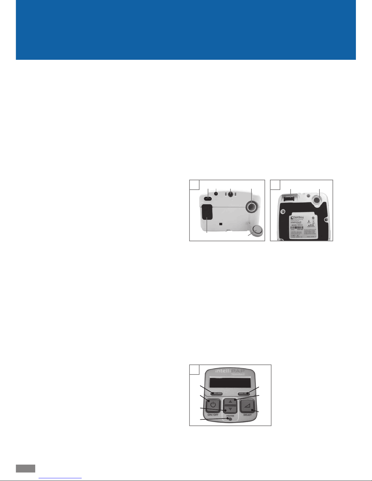
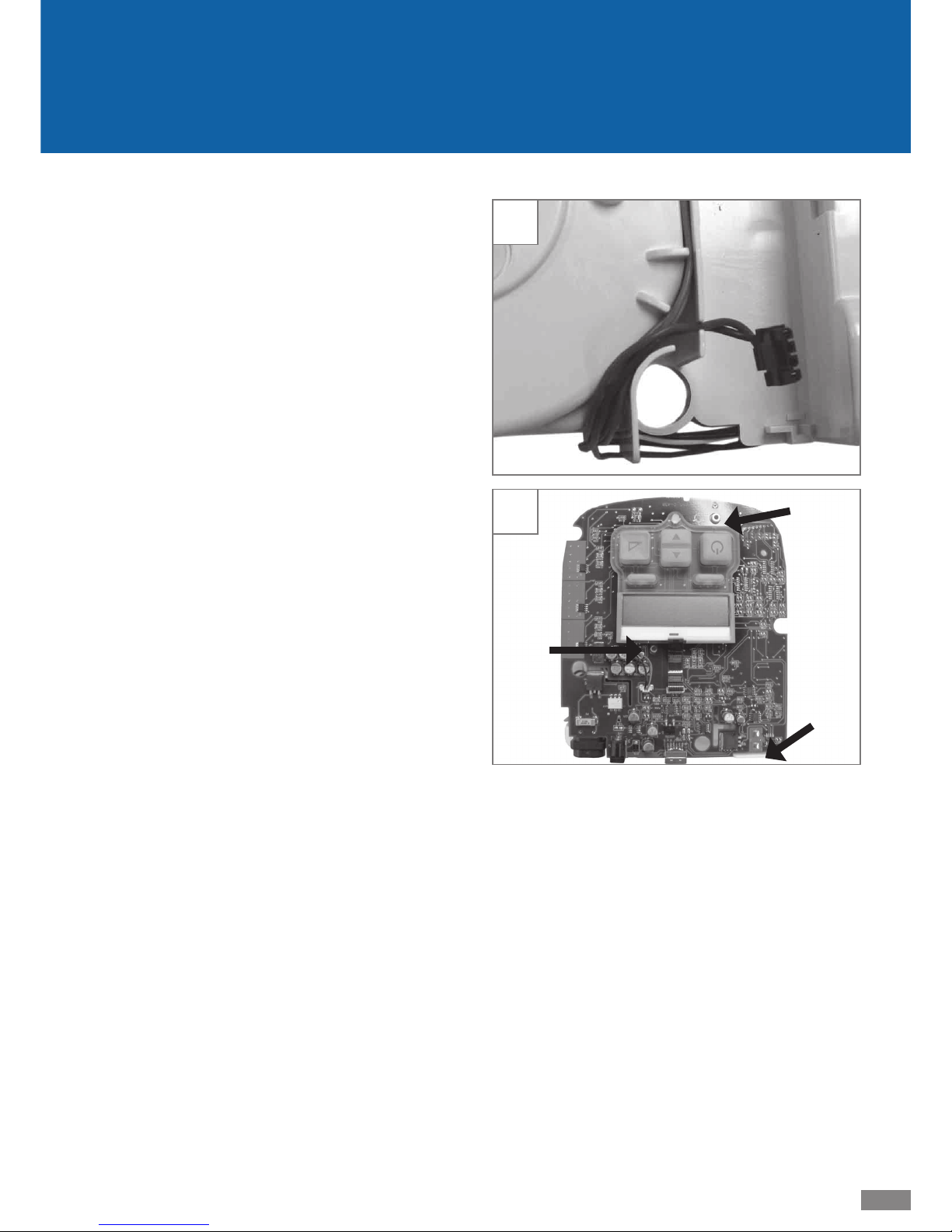
F. Images: DeVilbiss DV54/DV53 PAP
Figures A and B: DV54/DV53 Device Back and Bottom
1. Air supply port on back of device
2. Air supply port on bottom of device
(for optional humidifi er)
3. Air supply port plug
4. Heater power connector (for optional humidifi er)
5. AC power connector
6. DC power connector
7. Data por t
8. Air inlet fi lter opening
Figure C: Keypad
1. ON/OFF
2. Previous item
3. Next item
4. Delay
5. Decrease value
6. Increase value
7. Heater power LED
(for optional humidifi er)
C
5
1
2
4
6
3
7
B
2
4
A
1
3
56 7
8
Page 5

LT-2026
5
EN
2. Description of Normal Operation
An AC line cord (100-240 VAC, 50/60 Hz) or a DC line cord (12
VDC) supplies electrical power to the DV54/DV53 PAP. The
PAP converts the AC input voltage to DC voltage by means
of an internal switch mode power supply and uses the DC
voltage to power the internal electronics of the unit, such as
microcontroller, motor control circuitry, blower, LCD display,
etc. NOTE: The heated humidifi er will not operate when the
PAP uses external DC power.
The PAP produces positive pressure by spinning a reversecurved impeller with a brushless DC motor. Room air is drawn
through a fi lter into the blower, pressurized in the blower,
optionally passed through a heated humidifi er chamber, and
then discharged through a 22mm-ID, smooth-bore tube.
Pressure regulation is achieved using measured pressure as
feedback.
The DV54/DV53 PAP senses patient breathing by monitoring
changes in motor current: Breathing produces variations in
airfl ow; the airfl ow variations produce changes to the blower
load and result in variations to the motor current. A pressure
transducer triggers the auto-ON / auto-OFF functionality and
mask-OFF alerts.
Page 6

6
LT-2026
EN
A. Routine Cleaning–Patient
• Unplug the DV54/DV53 PAP and wipe enclosure with a
clean, damp cloth every few days to keep dust free. Allow
the device to dry completely before returning to power
source.
• Check the air-inlet fi lter every 10 days. Wash the dark
outer foam fi lter in a solution of warm water and mild
detergent. Rinse with water and allow the fi lter to dry
completely before returning to the device.
• Check the optional fi ne particle fi lter every 10 days and
replace if dirty or damaged.
• Clean the air supply tubing every day. Remove the tubing
from the device and mask and wash the inside of the tubing in a solution of warm water and mild detergent. Rinse
with water and allow to air dry before replacing device
and mask.
• Clean the mask and headgear according to the manufacturer’s instructions.
B. Disinfecting
CAUTION– Always work in an ESD (electro static discharge)
safe environment when assembling or disassembling
electronic components.
NOTE– DeVilbiss does not require disinfection as part of unit
maintenance. If disinfection is desired, the following procedure is recommended.
NOTE– Parts needed to perform the disinfection procedure
are NOT covered under the DV54/DV53 PAP warranty as
listed in this manual.
NOTE– Follow manufacturer’s instructions for cleaning and
disinfection solutions.
NOTE– Disinfection requires the following parts sold in Dis-
infection Kit, DV54/DV53D-682.
• Blower assembly, balanced
• Blower isolator-silicone
• Grommet-silicone
• 1/4 inch blower wrap foam
• 3 1/2 inch silicone tubing
• Air-inlet fi lter
• 5 1/2 inch silicone tubing—
discard, not needed for this model
• Tubing/Humidifi er air supply support plug
• 1/2 inch blower mount foam-round
• 1/2 inch top blower foam
• 1/8 inch inside bottom cover foam
• 5 inch silicone tubing
• Fine particle fi lter (optional)
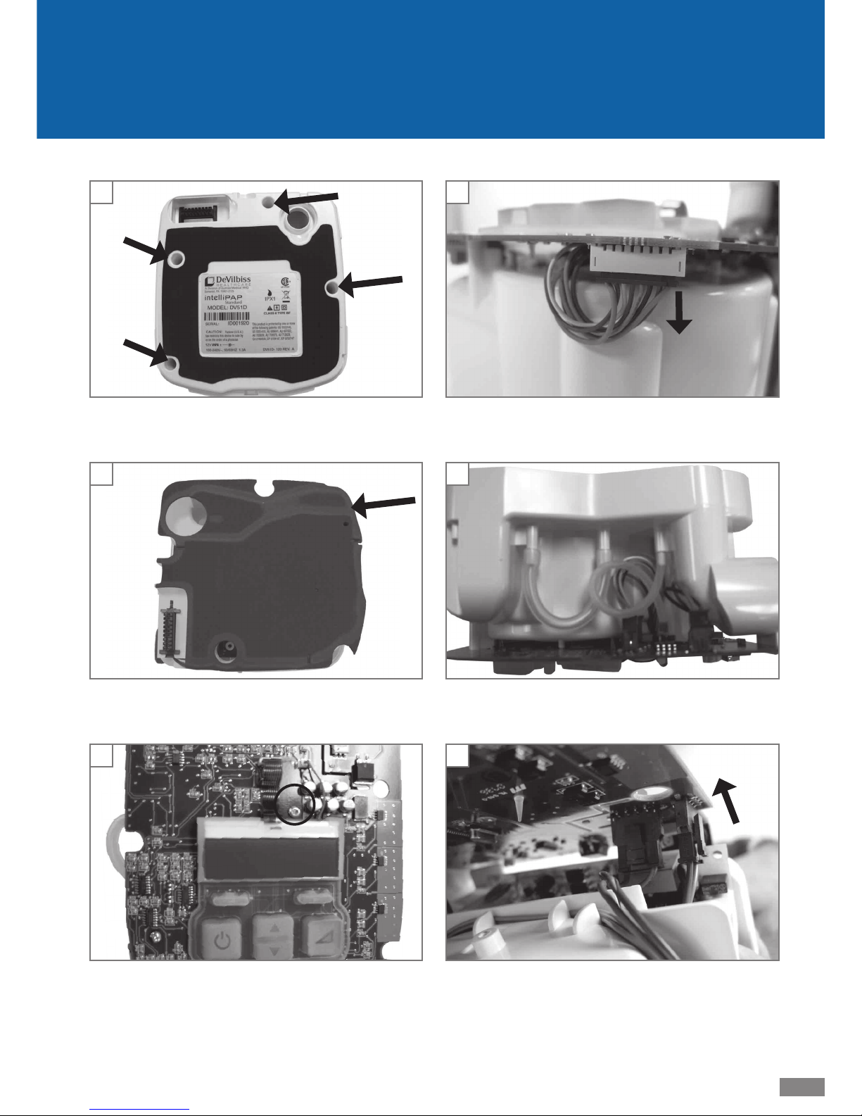
3. Cleaning and Disinfecting
Disinfection Procedure for the DV Series PAP
1. Make certain that the device is not connected to a power
source.
2. Dispose of the mask, headgear, air supply tubing, gray air
inlet fi lter and white fi ne particle fi lter, if applicable.
3. Place the unit, top side down, onto a clean work surface.
Remove the four (4) screws from the bottom cover and
remove the bottom cover from the unit. (Fig. 1)
4. Remove the black 1/8 inch foam from inside the bottom
cover assembly and discard. This foam may stick to the
chassis of the main unit. (Fig. 2)
5. Remove the black 1/2 inch top blower foam from the
chassis assembly and discard.
6. Turn the unit top side up and remove the top cover.
7. Using a T-15 driver, remove the screw holding the PC board
to the chassis. (Fig. 3)
8. Disconnect the 8-conductor blower wire harness from the
underside of the PC board. (Fig. 4)
9. Disconnect the two (2) pieces of tubing and discard. (Fig. 5)
NOTE– Pull the tubing straight off the connectors to prevent
damaging the chassis.
10. With the ports side of the chassis toward you, tilt the
PC board and its respective wire harnesses upward, and
remove the wire connections. Lift the PC board slowly so
that you can assist any wires that may become hung up
on the chassis or power supply. (Fig. 6)
Page 7
LT-2026
7
EN
41
3
2 5
6
Page 8
8
LT-2026
EN
7
8
9
10
11
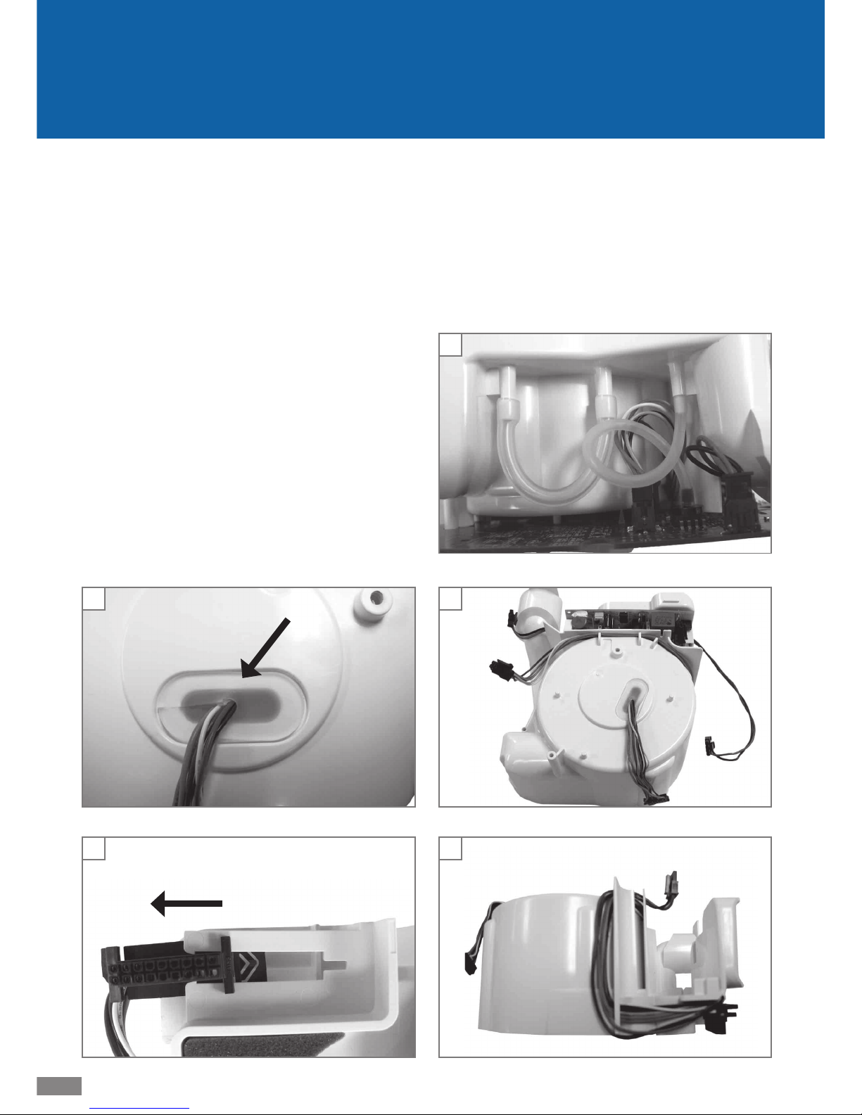
11. Remove the grommet that seals the blower’s wire harness.
(Fig. 7)
12. Remove the heater wire harness connector from the bottom of the chassis by sliding the connector outward while
pulling the top retaining tab upward slightly. (Fig. 8)
13. Remove the 1/4” blower wrap foam, the blower, and the
silicone isolator from the underside of the chassis.
14. Carefully spray, wipe or soak the air intake, fl ow path, and
blower chassis inside and outside using a 2% glutaraldehyde solution.
15. Wipe the power cord and the outside of both halves of the
PAP case with the same solution.
16. Let all components fully dry
17. Reassemble the unit using parts from the Disinfection
Kit—DV54/DV53D-682.
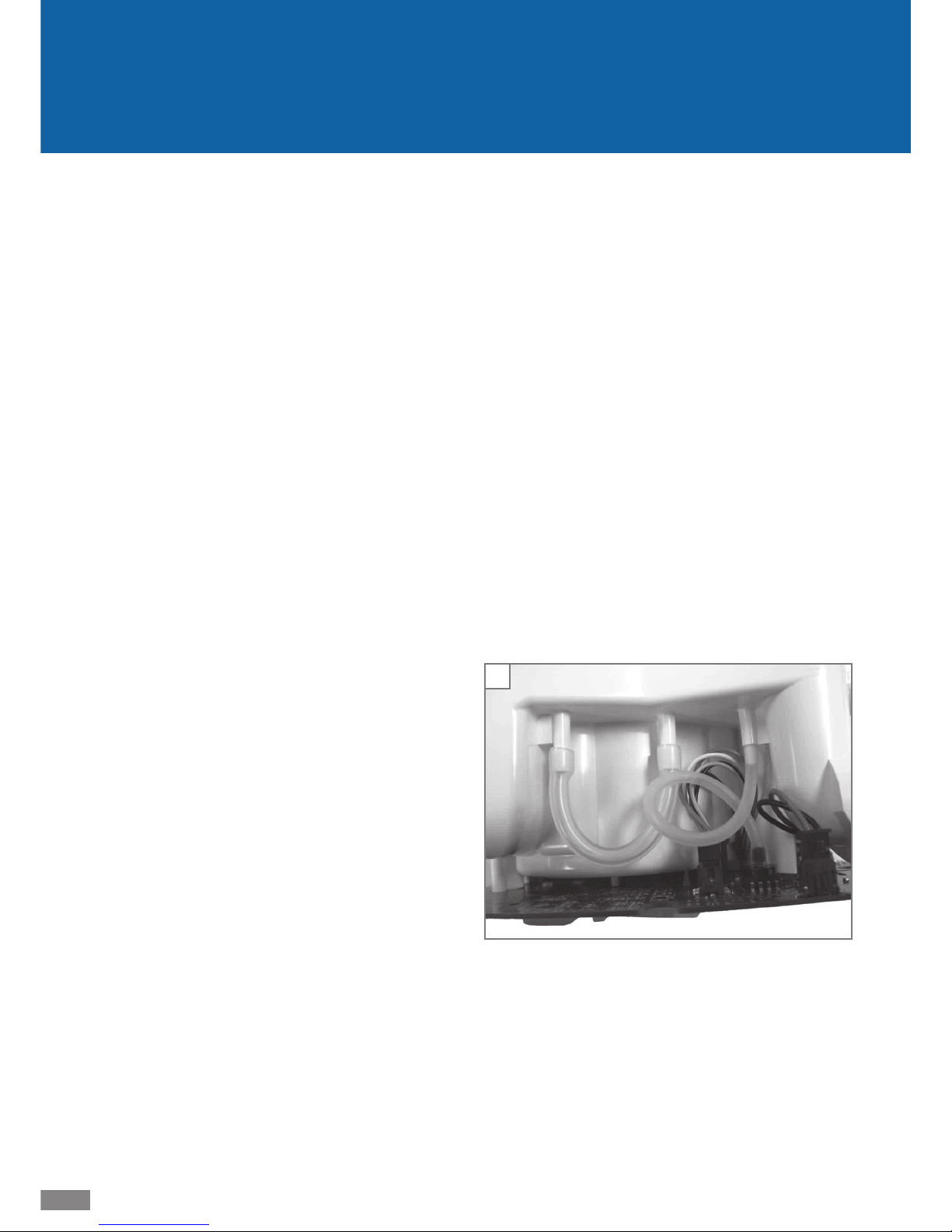
NOTES:
• Route the silicone tubing correctly, as shown, and ensure
that there are no kinks. (Fig. 9)
• Ensure that the silicone isolator is fully seated in the chassis and the blower.
• Ensure that the grommet is fully seated around the blower
wire harness.
• Route the wire harnesses properly, using the provided
strain reliefs on the chassis. (Fig. 10 & 11)
• Secure the power supply board within the mount clips on
the chassis before replacing the unit covers. (Fig. 10)
Page 9

LT-2026
9
EN
4. Maintenance
A. Initial Inspection—Equipment Provider
DeVilbiss recommends equipment inspection upon delivery
❏ Power up the DV54/DV53 PAP using AC power.
❏ Test pressure accuracy using an outlet cap (DV54/
DV53D-620), a calibrated pressure gauge and the procedures listed under Pressure Accuracy Test.
❏ Test the keys on the keypad using the procedures listed
under Keypad Test.
B. Routine Maintenance—Patient
❏ Wipe case with damp cloth every few days
❏ Check air-inlet fi lter every 10 days and clean as needed
❏ Clean air supply tubing daily
❏ Clean mask and headgear per manufacturer’s instructions.
C. Required three years Maintenance—
Equipment Provider
DeVilbiss requires the following maintenance from the equipment provider:
❏ Test pressure accuracy using procedures listed under Pres-
sure Accuracy Test. If the device is out of calibration, follow
corrective procedures as listed.
❏ Instruct patient on fi lter maintenance described in Instruc-
tion Guide:
Standard Filter
o Inspect fi lter every ten days
o Clean as needed
o Change every 6 months
Optional Fine Particle Filter
o Inspect fi lter every ten days
o Replace if dirty
o Change every 30 days
Page 10

10
LT-2026
EN
The following test procedures verify correct operation of the
DV54/DV53 PAP and should be performed on all repaired
units.
NOTE– Verify that the DV54/DV53 PAP contains the latest
fi rmware release before conducting maintenance or
repairs. Go to http://www.devilbisshealthcare.com/Products to download the latest fi rmware update. Download
and installation instructions are provided on the web site.
A. Pressure Accuracy Test
Additional equipment required: outlet cap (DV54/
DV53D-620), a calibrated pressure gauge (0-30 cmH2O, accuracy ±0.25 cmH2O)
1. Connect the pressure gauge to the unit outlet port.
2. Apply AC power to the unit. If the blower is running, press
the ON/OFF key on the keypad so that the blower stops
and the LCD displays ‘OFF’.
3. While pressing both the Down Arrow and Delay keys,
press the ON/OFF key to start the blower and enter clinical
mode.
4. Press the Next Item key until Set Pressure is displayed.
Use the Up and Down Arrow keys to adjust the pressure
to 12 cmH2O. Wait at least 30 seconds for the pressure to
stabilize.
5. Verify that the displayed pressure matches the pressure
measured on the gauge (pressure setting ±1.0 cmH2O).
Accuracy at other pressure settings can be checked if
needed.
6. If the pressure is out of calibration, turn the blower OFF for
approximately 1 minute to allow auto-calibration to occur.
Turn the blower back ON and allow 30 seconds for the
pressure to stabilize. If the pressure is still out of calibration, perform a full calibration using the Manual Calibration Procedure.
7. If manual calibration does not improve pressure accuracy,
there may be a problem with the fl ow path or control
board. Refer to Troubleshooting.
5. Testing
B. Keypad Test
No additional equipment required.
1. Apply AC power to the unit. If the blower is running, press
the ON/OFF key on the keypad so that the blower stops
and the LCD displays ‘OFF’.
2. While pressing both the Down Arrow and Delay keys,
press the ON/OFF key to start the blower and enter clinical
mode.
3. Press the Next Item key until Delay Time is shown on the
LCD display.
4. Note the Delay Time; then change it by pressing the Up and
Down arrow keys. Use the arrows keys to return the Delay
Time back to the original setting.
5. Use the Previous Item key to return to the Set Pressure
screen.
6. If any of the keypad keys did not function correctly during this test, replace the PC control board using Service
Instruc tions.
Page 11

LT-2026
11
EN
C. Auto-ON / Auto-OFF Test
Additional equipment required: 6 ft x 22 mm smooth bore
tubing.
1. Apply AC power to the unit. If the blower is running, press
the ON/OFF key on the keypad so that the blower stops
and the LCD displays ‘OFF’.
2. While pressing both the Down arrow and Delay keys,
press the ON/OFF key to start the blower and enter clinical
mode.
3. Press the Next Item key until Enable Menu is displayed,
then press the Down Arrow key to enter the sub-menu.
4. Press the Next Item key until the Auto-ON setting is displayed. Use the UP or DOWN arrow keys to set the value
to Enabled.
5. Press the Next Item key until the Auto-OFF setting is displayed. Use the UP or DOWN arrow keys to set the value
to Enabled.
6. Press the ON/OFF key on the keypad so that the blower
stops and OFF is displayed on the LCD.
7. Connect the 6 ft x 22 mm smooth bore tubing to the
CPAP and block the airfl ow with your hand or a plug.
8. Turn the blower ON by pressing the ON/OFF key on the
keypad.
9. Keep the airfl ow blocked for two minutes. Verify that the
blower continues running and no mask alerts appear.
10. Unblock the smooth bore tubing to open the unit’s airfl ow.
11. Verify that after approximately 10 seconds the LCD shows
‘Mask OFF’. If the mask alert did not appear, go to step 14.
12. After another 20 seconds the blower should turn OFF via
the Auto-OFF feature. Wait approximately two minutes
after the blower turns OFF. Verify that the blower does not
turn back ON without breathing present.
13. Tap the palm of your hand on and off the end of the tubing to simulate breathing and verify that the blower turns
ON via the Auto-ON feature.
14. If the Auto-OFF or Auto-ON features do not work correctly,
perform a full calibration using the Manual Calibration
Procedure.
D. Backlight Test for LCD and Keypad
No additional equipment required.
1. Apply AC power to the unit. If the blower is running, press
the ON/OFF key on the keypad so that the blower stops
and the LCD displays OFF.
2. Press the ON/OFF key and verify that the LCD and keypad
backlights are lit.
3. Wait one minute and verify that the LCD and keypad backlights reduce intensity.
4. Press any keypad key, except ON/OFF, and verify that the
LCD and keypad backlights return to full intensity.
5. If the LCD or keypad backlights did not function correctly
during this test, replace the LCD, keypad and/or PC control
board.
Page 12

12
LT-2026
EN
6. Alerts and Device Faults
A. Alerts Visible to Patients
Alert Description
Delay running
XX minutes left
Comfort Delay is active
Mask off. Please check
mask fi t.
High airfl ow during use
(Poor mask fi t or mask
removed)
Device Fault E0X. Call
provider.
Device error (See next table.)
B. Device Faults Visible to Patients
Only device faults classifi ed as critical are visible to the patient
on the LCD display.
These faults can be corrected by a service technician.
Device
Fault
Description
E01
Read Setting Error. Stored prescription settings are corrupted. Unit is in fail-safe state
(blower off) when this error displays. See
Troubleshooting and Service Instructions to
correct fault, or return unit for repair.
E03
Motor Error. Unit attempts to drive the motor, but the blower is not spinning (zero motor
speed). See Troubleshooting and Service
Instructions to correct fault, or return unit for
repair.
E04
Locked Rotor Error. Average motor speed is
low, while the motor current is high, for several
seconds. See Troubleshooting and Service
Instructions to correct fault, or return unit for
repair.
E07
Motor Fault Error. The motor control chip fault
output goes active low for a fi xed period of
time. See Troubleshooting and Service Instructions to correct fault, or return unit for repair.
C. Reading and Clearing the Last Device
Fault Code
NOTE– The last device fault code is stored in EEPROM to assist
in fi eld service of the unit.
Additional equipment: IBM or Compatible PC with a free serial
port, PAP to PC cable (DV54/DV53D-615), a terminal program
(Microsoft Windows HyperTerminal or equivalent).
1. Connect the DV54/DV53 PAP to the PC serial port with
PAP to PC cable.
2. Apply AC power to the unit. If the blower is running, press
the ON/OFF key on the keypad so that the blower stops
and the LCD displays ‘OFF’.
3. Use a terminal program (such as Windows HyperTerminal,
or equivalent) with COM settings 9600 baud, no parity, 8
data bits, 1 stop bit, and Flow Control set to none.
4. When connection is established with the PAP, the terminal
program will show: ‘RI;’ every 0.5 seconds. This display
indicates that the PAP is waiting for a handshake.
5. Type ‘ri’ (all commands are case sensitive) and press Enter.
The PAP should respond with the fi rmware version in the
form “V0.XX mm/dd/yyyy.” Repeat this step if necessary
to complete the handshake.
6. Request the last alert code and date by typing ‘El’ and
pressing Enter. The return value will be in the form ‘Exx
dd/mm/yyyy’. Exx is the alert code and dd/mm/yyyy is
the date the error occurred.
7. Clear the last alert code by typing ‘Ec’ and pressing Enter.
The PAP will respond with ‘OK’.
Page 13

LT-2026
13
EN
A. Manual Calibration
DeVilbiss recommends calibrating the DV54/DV53 PAP if
replacing the PC control board or when testing or troubleshooting indicate calibration is required. The manual
calibration procedure accesses a terminal program via the
unit’s communication port to calibrate the internal pressure
sensor and the motor current circuitry. Progress and confi rmation messages display on the terminal screen throughout
the procedure. If a failure occurs during calibration, the error
displays as well. See Calibration Errors below.
Additional equipment: IBM or Compatible PC with a free serial
port, PAP to PC cable (DV54/DV53D-615), a terminal program
(Microsoft Windows HyperTerminal or equivalent) and a
calibrated pressure gauge (0 to 30 cmH
2
O).
Please read all steps before beginning this process.
NOTE– Details on the Tc serial commands used in this proce-
dure are listed in Section D.
1. Use the PAP to PC cable to connect the DV54/DV53 PAP to
a PC serial port and apply AC power to the PAP.
2. Use a terminal program (such as Windows HyperTerminal,
or equivalent) with COM settings 9600 baud, no parity, 8
data bits, 1 stop bit, Flow Control set to none.
3. When connection is established with the PAP, the terminal
program will show: ‘RI;’ every 0.5 seconds. This display
indicates that the PAP is waiting for a handshake.
4. Type ‘ri’ (all DV54/DV53 commands are case sensitive)
and press ENTER. The PAP will respond with the fi rmware
version in the form ‘V0.XX dd/mm/yyyy’. Repeat this
step if necessary to complete the handshake.
5. Start the calibration process by typing ‘Tc= s’ and pressing
ENTER. The PAP will respond with
‘Calibration Started’. If the unit responds with ‘WF’,
resend the ‘Tc=s’ command.
6. The PAP will begin sending messages and prompting for
responses to complete the calibration. NOTE: If a calibration failure is encountered at any stage during the procedure, the PAP will respond with ‘Cal failed: EXX’,
where XX is a two digit error code.
a. PAP sends ‘Waiting for blower to stop spin-
ning’.
b. PAP sends ‘Cal press offset’ when spinning is
stopped.
During this stage of the procedure the PAP stops the
blower and saves the pressure sensor and motor current
offsets. After a short delay, the PAP increases the pressure
to approximately 20 cmH
2
O.
c. PAP sends ‘Set pressure to 20 cmH2O using
Tw+, Tw-, or Tw=’ ‘Send Tc=y when ready’
d. Connect the pressure gauge to the PAP outlet (the
7. Calibration
outlet should be in a deadhead or zero fl ow condition)
and, using the computer keyboard (‘Tw+’ followed by
ENTER increases the pressure and ‘Tw-’ followed by
ENTER decreases the pressure), adjust the PAP pressure
to 20 cmH2O (± 0.1 cmH2O), then type ‘Tc=y’ followed
by ENTER.
e. PAP sends ‘Reading and saving pressure hi
cal’ after confi rming that the pressure is correct.
During this stage of the procedure, the PAP calibrates
the pressure sensor by reading and saving the high
pressure calibration value.
NOTE– As an alternative to steps d and e, the current PAP
pressure gauge reading can be sent to the PAP from the
terminal. Perform the following steps for this option:
Use the ‘Tw+’, ‘ Tw-’, or ‘Tw=X’ (where X is a number
between 0 and 1023 to adjust the pressure to a value
between 15 and 30 cmH2O.
If the pressure is already within this range no adjustment
is needed.
NOTE: A more accurate calibration will be obtained, if the
value is close to 20 cmH2O.
7. Send the pressure to the PAP in the format ‘Tc=yxxxxx’,
where xxxxx is the gauge pressure in cmH2O multiplied
by 1000 (Example: 20 cmH2O is sent as ‘Tc=y20000’. )
8. After a short delay the PAP will respond with ‘cal suc-
cessful’. Calibration is now complete. Please check the
PAP pressure settings for accuracy.
Page 14

14
LT-2026
EN
B. Calibration Errors
Code Description
E95
Calibrate Motor Stop Error. The blower did
not stop during device calibration. This error only
occurs during the calibration procedure.
C. Auto-Calibration
The DV54/DV53 PAP automatically adjusts calibration to
maintain accuracy over time and under varying operating
conditions. Each time the blower is turned OFF, the PC control
board reads and saves the offset voltages from the pressure
transducer. The PAP uses these voltages to maintain calibration accuracy as the unit is used over time.
D. Details on Tc Serial Command
Tc serial commands are used in the manual calibration procedure listed in Section A. The ‘Tc’ command on the terminal
program reads the unit’s current calibration values, starts
the calibration procedure, and handles user feedback during the calibration process. Refer to the manual calibration
procedure for details on the calibration process.
• Sending ‘Tc=s’ to the PAP starts the calibration process.
• Sending ‘Tc’ without a modifi er requests the current
calibration values. A comma-separated list of all cal values
is returned.
Comma-separated response to ‘Tc’ with no modifi er:
llll,hhhh,mmmm<cr>
o llll is the pressure low cal (sensor offset). Convert to
voltage by dividing by 1024 and multiplying by 5.
o hhhh is the pressure high cal (sensor output at 20
cmH2O). Convert to VDC by dividing by 1024 and multiplying by 5.
o mmmm is the motor current calibration (adc offset)
• Feedback is provided to the calibration task by sending
‘Tc= y’ when prompted.
Page 15

LT-2026
15
EN
Symptom
Action (for symptoms listed at left, follow the
steps listed below)
Blower
does not
start when
powered
up
1. Remove the cover. See Service Instructions.
2. Search for disconnected wire harnesses
and reconnect, if needed.
3. Determine if fuses are open.
Without AC power to the unit, measure
the resistance across the F1 fuse with an
ohmmeter. If 0.0 to 0.5 ohms of resistance
are not present across the fuse, the fuse is
open and the power supply board should
be replaced. See Service Instructions.
Without AC power to the unit, measure
the resistances across the F2 and F3 fuses
with an ohmmeter. If 0.0 to 0.5 ohms of
resistance are not present across either
fuse, the fuse is open and the PC control
board should be replaced. See Service
Instruc tions.
4. If all fuses are closed, install a blower
known to operate properly, see Service
Instructions, and power up the unit.
If the new blower operates properly,
replace the old blower.
If the new blower does not operate prop-
erly, replace the control board. See Service
Instruc tions.
5. Replace the cover. See Service Instructions.
E03, E04,
or E07
errors
display
OR display
is blank
E01
error code
displays
Replace the control board
Blower is
loud
1. Remove the cover and control board. See
Service Instructions.
2. Inspect the assembly of the foam, blower,
and silicone isolator. See Blower Replacement instructions for correct placement.
3. Inspect the blower for visible space between the blower halves and press halves
back together, if needed.
4. If the assembly is not correct, reassemble
the components.
5. If assembly is correct, replace the blower.
See Service Instructions.
6. Replace the control board and cover. See
Service Instructions.
8. Troubleshooting
Symptom
Action (for symptoms listed at left, follow the
steps listed below)
Pressure
out of
tolerance
(Pressure ±
1.0 cmH
2
O
of setting)
1. Remove the cover. See Service Instructions.
2. Search for disconnected, occluded, or
kinked tubing on the pressure sensor or
chassis. Correct any issues.
3. Search for damage to any foam pieces
and/or tubing and replace the component, if damaged.
4. Remove the control board. See Service
Instructions.
5. Search for signs of water damage to the
blower assembly, pressure sensor and
replace the component, if damaged.
6. Inspect the blower. If a space is visible
between the top and bottom sections,
press the halves together to eliminate the
space.
7. Repeat the pressure test.
8. If the pressure remains out of tolerance,
re-calibrate the unit. See Service Instructions.
9. If the pressure remains out of tolerance,
replace the control board. See Service
Instruc tions.
10. Replace cover. See Service Instructions.
Calibration
failure–
Error code
E95
Display on
terminal
program
during
calibration.
1. Remove the cover. See Service Instructions.
2. Search for damage, and/or loose connections, on the air intake fi lter, intake
foam components, and all internal tubing
and replace or reconnect components, if
needed. Search for disconnected, occluded, or kinked tubing on the pressure sensor and chassis and reconnect or replace
tubing, if needed.
3. Remove the control board. See Service
Instruc tions.
4. Search for signs of water damage to the
blower assembly, pressure sensor and
replace, if damaged.
5. Inspect the blower. If a space is visible
between the top and bottom sections,
press the halves to eliminate the space.
6. Repeat Manual Calibration Procedure.
7. If the error codes are not resolved, replace
the control board. See Service Instructions.
8. Replace the cover. See Service Instructions.
Page 16
16
LT-2026
EN
C. Control PC Board Removal
CAUTION– Failure to wear anti-static equipment during ser-
vice may damage
this device.
1. Remove the cover. See instructions above.
2. Wearing an anti-static device, lift the cover off the chassis
and place it, with the control board facing up and the
blower facing down, onto a clean fl at surface.
3. Disconnect the two pieces of tubing from the outlet port
side of the chassis.
4. Disconnect accessible wire harnesses: one behind and one
to the left of the tubing in step 3, one at the right corner
under the keypad, and one on the outside of the power
supply board.
5. Remove one T-15 screw, located near the middle of the
board beside LCD screen. Lift the board off the chassis
slowly and disconnect any remaining wire harnesses from
the control board.
6. Place control board keypad facing down onto a clean, fl at,
static-free surface, if returning to the unit.
NOTE– After performing any service on the DV54/DV53 PAP,
please test the unit to ensure proper operation and calibrate, if necessary.
A. Cover Removal
CAUTION– Failure to wear anti-static equipment during ser-
vice may damage
this device.
1. If using a DV5HH, remove the heated humidifi er and unplug the tubing/humidifi er air supply support plug from
the back of the cover and re-plug it in the outlet on the
bottom cover.
2. Position the PAP on a clean, fl at surface with the keypad
facing down.
3. Remove four T-20 screws from the bottom cover.
4. Lift the bottom cover straight up off the top cover.
NOTE– Attempting to reorient the PAP in order to lift the
top cover, instead of the bottom cover, may damage this
device.
5. Wearing an anti-static device, turn the unit over and lift
the top cover off the chassis.
B. Cover Replacement
CAUTION– Failure to wear anti-static equipment during ser-
vice may damage
this device.
1. Wearing an anti-static device, search for and connect all
loose wire harnesses.
2. Place the top cover onto the chassis, with the keypad
facing the cover and fi tting the control board around the
screw posts in the cover.
3. Connect all tubing, carefully creating the correct loops and
eliminating any kinking. (Fig. 1)
4. With the 1/8 inch inside bottom cover foam oriented
correctly and lying fl at, place the bottom cover over the
chassis and onto the top cover, fi tting the screw posts into
proper alignment with the chassis and moving any protruding wire harnesses and tubing away from the edges of
the cover.
5. Replace four T-20 screws.
9. Service Instructions
1
Page 17
LT-2026
17
EN
D. Control PC Board Replacement
CAUTION– Failure to wear anti-static equipment during ser-
vice may damage
this device.
1. See instructions above to remove the cover and the control PC board.
2. Wearing an anti-static device, verify that the silicone rattails holding the keypad and LCD display onto the control
board are pulled through the appropriate holes in the
board. See Keypad & LCD Display instructions.
3. Place the chassis on a clean fl at surface with the blower
facing down. Orient the replacement board so that the
keypad is over the rounded end of the chassis.
4. Tilt the board and connect the two wire harnesses near
the power supply board and insert the brown and blue
wires into the notch on the chassis. Tilt the board and
connect the two wire harnesses near the outlet port.
Connect the wire harness near the right corner of the
keypad. (Fig. 2)
5. Position the board (Fig. 3) so that: the hole on the board
(A), located below the ON/OFF key, is over the peg on the
chassis; the small hole (B), located near the LCD screen, is
over the screw hole on the chassis; and the cut-out (C) on
the left rear corner fi ts around the protrusion above the
air outlet port on the chassis. Move any stray tubing from
between the board and the chassis, verify that all wire harnesses are properly routed, and replace the T-15 screw on
the board.
6. Replace the cover. See instructions above.
7. Connect the CPAP to a PC serial port with cable DV54/
DV53D-615 and turn the CPAP on.
8. Use a terminal program (such as Windows HyperTerminal,
or equivalent) with COM settings 9600 baud, no parity, 8
data bits, 1 stop bit, Flow Control set to none.
9. When connection is established with the CPAP, the
terminal program will show: “RI;” every 1/2 seconds. This
display indicates that the CPAP is waiting for a handshake.
10. Type ‘ri’ and press ENTER. The CPAP should respond with
the fi rmware version in the form “V0.XX dd/mm/yyyy.”
Please note that all commands are case sensitive. Repeat
this step if necessary to complete the handshake.
11. Type ‘Mn<cr>’. The CPAP will report the model number
saved in memory, it should be “000000” if the PC board is
new.
12. Read the model number from the CPAP label on the bottom of the unit (EX: DV54SE).
13. Type ‘Mn=nnnnnn<cr>’ where nnnnnn is the 6 digit
model number read in the previous step (use a space for
the last digit if necessary to make the string 6 digits). The
CPAP should return the new six-digit model number.
14. Type ‘Sn<cr>’. The CPAP will report the serial number
2
3
A
B
C
saved in memory, it should be “00000000” if the PC board
is new.
15. Read the serial number from the CPAP label on the bottom
of the unit.
16. Type ‘Sn=nnnnnnnn<cr>’ where nnnnnnnn is the 8 digit
serial number read in the previous step. The CPAP should
return the new eight-digit serial number.
Page 18

18
LT-2026
EN
17. Read the Hour Meter (“Uh<cr>”)– a new PC board should
have 00000 hours. It is recommended that the original
hour meter value be restored if the original blower is used.
Set the hour meter by sending ‘Uh=nnnn<cr>’ where
nnnn is the hour meter reading x 10 (Ex: 100.5 hours
would be set by typing ‘Uh=1005<cr>’).
18. Read the Compliance Meter (“Up<cr>”)– a new PC board
should have 00000 hours. Clear the Compliance meter if
it is not zero by typing ‘Up=c<cr>’. The CPAP will return
000000.0 hours.
19. Check the fi rmware and hardware version information.
Read and record the following:
• BIOS rev “VB<cr>”
• Firmware rev “VF<cr>”
Check the present version of fi rmware to make sure the
board is up to date. Install new fi rmware if the board has
an old version.
20. Check for last saved error, type ‘El<cr>’. The CPAP will
respond with “Exx dd/mm/yyyy” where xx is the last
saved error code and dd/mm/yyyy is the date that the
error was detected. Clear the last error by typing ‘Ec<cr>’,
the CPAP will return “OK.” Verify that the error code is “00”
by typing ‘El<cr>’.
21. Set all device settings to their default values by typing
‘TD<cr>’. The CPAP should return “OK.”
22. Recalibrate the unit.
E. Power Supply Board Removal
CAUTION– Failure to wear anti-static equipment during ser-
vice may damage
this device.
1. See instructions above to remove the cover and the control PC board.
2. Wearing an anti-static device and with the power supply
board facing you, apply thumb pressure to top left corner
of the board while pulling the top right corner up and out
of the mount clip at its bottom.
3. Pulling the top left corner out of its mount clip, lift the
board off the chassis.
4. If returning the power supply board to the unit, place the
board onto a clean, fl at, static-free surface with its large
components facing up OR if discarding the power supply
board, remove the two wire harnesses for use with the
replacement board or purchase a new wire harness kit.
F. Power Supply Board Replacement
CAUTION– Failure to wear anti-static equipment during ser-
vice may damage
this device.
1. See instructions above to remove the cover, the control PC
board and the power supply board.
2. Wearing an anti-static device, connect the wire harnesses
from the old power supply board to the new power supply
board or use a new wire harness kit.
3. Position the chassis so that the blower faces down and the
inlet and outlet ports face you. Position the power supply
board so that the components are facing away from you
with the large brown component in the bottom left corner and the small blue component in the top right corner.
4. Place the board into the mount clips at the bottom of the
power supply board cavity and press down fi rmly on the
top corners until the board is fully mounted.
5. See instructions above to replace the control PC board and
the cover.
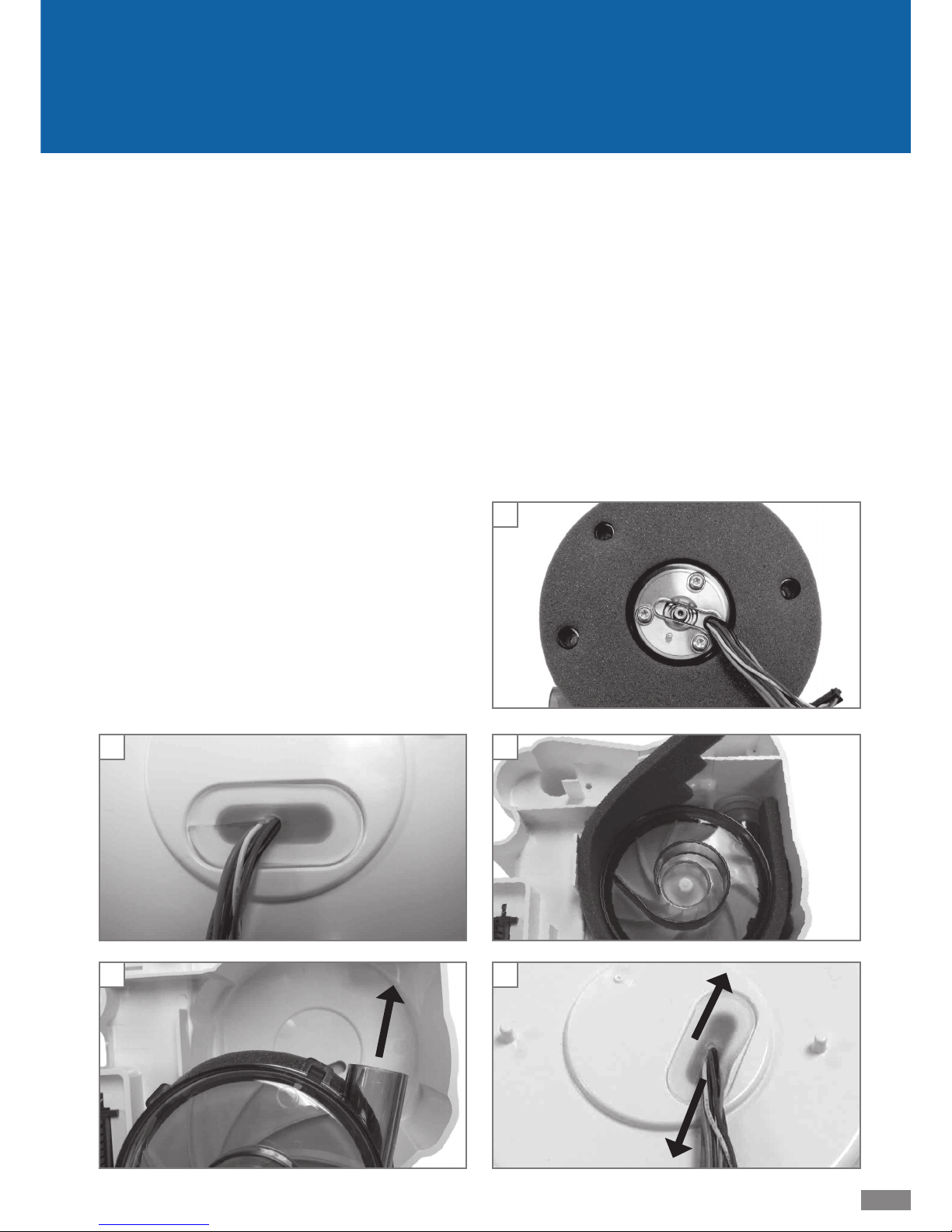
G. Blower Removal
CAUTION– Failure to wear anti-static equipment during ser-
vice may damage
this device.
1. See instructions above to remove the cover and control PC
board
2. Carefully remove the silicone grommet holding the blower
wire harness. (Fig. 4)
3. Holding the wire harness in your hand, turn the chassis
over so that the blower is facing up.
4. Remove the foam covering the blower and the foam
around the blower.
5. Reach into the blower cavity and push the silicone isolator off
the blower outlet. (Fig. 5)
6. Slowly lift blower out of the chassis and carefully pull the
wire harness through the hole in the chassis. If not returning blower to unit, remove foam from bottom of blower
and save for new blower.
Page 19
LT-2026
19
EN
6. Insert the top blower foam so that it conforms to the
edges of the blower cavity portion of the chassis.
7. Turn the chassis over so that the blower is facing down.
Gently pull any slack from the wire harness. Insert the
silicone grommet into the hole in the chassis so that the
slit in the grommet is toward the power supply board
location, all the wires are in the center hole of the grommet and the grommet fl ange is fully sealed. Route the wire
harness along the top of the chassis and down the front of
the blower cavity portion of the chassis. (Fig. 8)
8. See instructions above to replace the control PC board and
the cover.
H. Blower Replacement
CAUTION– Failure to wear anti-static equipment during ser-
vice may damage this device.
1. See instructions above to remove the cover, control PC
board and blower.
2. Insert the blower mount foam on the blower base so that
the holes in the foam align with the protrusions on the
blower and the blower wire harness is through the center
hole in the foam. (Fig. 6)
3. Turn the blower over so that the motor is facing down.
Guide the wire harness through the hole in the bottom of
the blower cavity portion of the chassis.
4. Lower the blower with its outlet port pointing at the
silicone isolator. Position the blower’s outlet port into the
top edge of the silicone isolator then tilt the outlet port
into the isolator opening without folding the isolator. Push
the outlet port into the isolator until the port is evenly
inserted into the isolator. See isolator image in Blower
Removal instructions.
5. Insert the blower wrap foam so that the single-notched
end is beside the blower outlet port. Wrap the remaining foam strip clockwise around the blower so that the
notched foam corresponds to the latches on the blower
body. Wrap the double-notched end around the blower
and over the outlet port. The top edge of the foam should
be almost fl ush with the blower. (Fig. 7)
4
6
7
Slit direction
harness direction
8
Page 20
20
LT-2026
EN
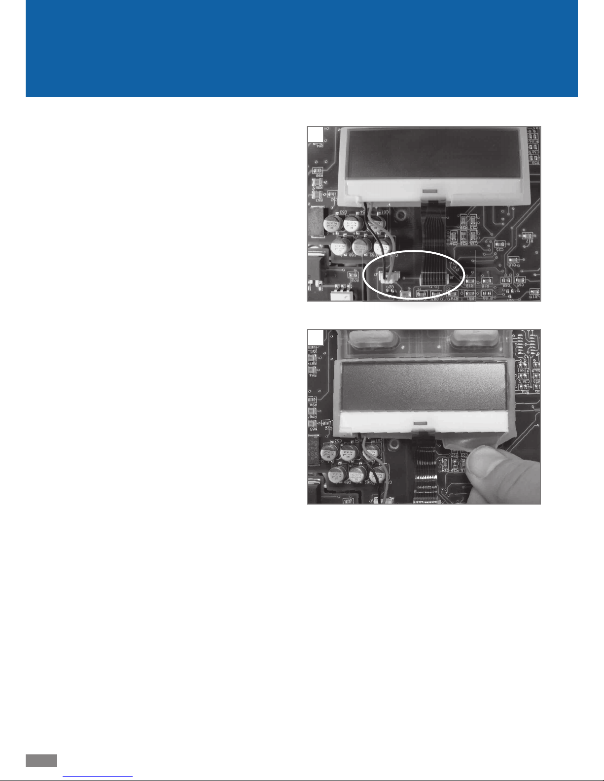
I. KeyPad & LCD Display Removal and
Replacement
CAUTION– Failure to wear anti-static equipment during ser-
vice may damage
this device.
1. See instructions above to remove cover and control PC
board.
2. Wearing an anti-static device, disconnect the two LCD
display wire harnesses. (Fig. 9)
NOTE– Do not touch the exposed contact area on the end of
the ribbon cable. Dirt and oils may damage it.
3. Gently roll the silicone frame away from the edges of the
LCD display screen (Fig. 10), lift the display off the keypad
and place it on a clean, fl at, anti-static surface, if returning
to the unit.
4. Lift the keypad off the board, gently pulling three silicone
rattails through the board.
NOTE– Do not touch the keypad contacts on the PC board.
Dirt and oils may damage them.
5. Replace the keypad by inserting the silicone rattails on the
replacement keypad through appropriate holes on the
control board and gently pulling the rattails through the
holes.
6. Insert the LCD display into the silicone frame on the
keypad and connect the wire harnesses to the appropriate
connectors on the board.
7. See instructions above to replace the control PC board and
the cover.
9
10
Page 21

LT-2026
21
EN
Unit Specifi cations
Size 4.2” H x 6.5” W x 6.9” D (10.7 cm x 16.5 cm x 17.5 cm)
Weight 2.7 lbs. (1.22 kg)
Electrical Requirements 100-240V~, 50/60 Hz
D.C. Operation 12 volts at 5 amps
Maximum Power Consumption 65 watts max from AC power source (PAP device only)
CPAP Pressure Range 3-20 cmH
2
O
Operating Temperature Range 41°F to 104°F (5°C to 40°C)
Operating Humidity Range 0% to 95% RH non-condensing
Operating Atmospheric Conditions Sea level to 9,000 feet
Storage & Transportation Temperature Range -40°F to 158°F (-40°C to +70°C)
Storage & Transportation Humidity Range 0% to 95% RH non-condensing
Maximum Limited Pressure 20 cmH
2
O under normal use
Sound Level 26 dBA
Filter Specifi cations
Standard Filter > 3.0 micron particles
Optional Fine Particle Filter > 0.3 micron particles
Max Flow Rates
83 L/m @ 6.5 cmH2O (1/3 max pressure)
134 L/m @ 13 cmH
2
O (2/3 max pressure)
163 L/m @ 20 cmH
2
O (max pressure)
Pressure Accuracy ± 1.0 cmH
2
O
Pressure Swings (cmH
2
O peak to peak at 500mL tidal volume, sine wave profi le)
Breaths per
minute
10 15 20
@ 6.5 cmH
2
O 0.5 0.5 0.5
@ 13 cmH
2
O 1.0 1.0 1.0
@ 20 cmH
2
O 1.0 1.0 1.0
Other Specifi cations
Equipment classifi cation with respect to protection
from electric shock
Class II
Degree of protection from electric shock Type BF Applied Part
Degree of protection against ingress of liquids IPX1
Drip Proof Equipment not suitable for use in the presence of a fl ammable anesthetic
mixture with air or with oxygen or nitrous oxide.
Mode of operation Continuous
Clinical Specifi cations for Digital Outputs
Pressure 0 to 25.5 cmH2O ± 1.0
Page 22

22
LT-2026
EN
11. General Information DV5HH
A. Safeguards
When servicing electrical products, basic safety precautions
should always be followed. Important safety information in
this manual is highlighted by the following terms.
DANGER: Urgent safety information for hazards
that will cause serious injury or death.
WARNING: Important safety information for hazards
that might cause serious injury.
CAUTION: Information for preventing damage to the
product.
NOTE: Information to which you should pay
special attention.
PLEASE READ ALL INSTRUCTIONS BEFORE
SERVICING THIS DEVICE.
DANGER!
• Electric Shock Hazard – Do not use while bathing.
• Electric Shock Hazard – Do not immerse this device into
water or any other liquid.
• Electric Shock Hazard – Do not attempt to open or remove the enclosure. There are no user-serviceable internal
components. If service is required, return the product to
your home care provider. Opening or tampering with the
product will void the warranty.
WARNING!
• Use the Heated Humidifi er system only for its intended
use as described in this manual.
• Be sure to read and understand all safety instructions
supplied with your IntelliPAP or SleepCube fl ow generator device.
• Use only accessories recommended by DeVilbiss.
• Always remove the water chamber from the humidifi er
cradle for fi lling.
• Use only tubing recommended or supplied with the fl ow
generator.
• If water has been spilled onto the cradle or it has been
submerged into water, unplug the power cord from the
power source immediately. Allow the device to completely
dry before use.
• If the device has been dropped, refer to the troubleshooting guide for instructions. Contact your homecare provider
for evaluation of the device.
• Never block the air openings of the cradle or chamber. Do
not insert any objects into any openings or tubes.
• For proper operation of the humidifi er, the device must be
placed on a fl at, level surface.
• Never place the system on a soft surface such as a bed or
couch during operation.
• This heated humidifi er is intended for single-patient
use only.
B. Travel
The DeVilbiss DV5HH humidifi er system
• Automatically accepts line voltages of 100-240 V, 50/60 Hz
• Needs power cord appropriate for area
o USA DV54/DV53D-606
o Europe, except UK DV54/
DV53D-607
o UK DV54/DV53D-608
o Australia DV54/
DV53D-609
o Set of 3 (UK, Europe, Australia) DV54/
DV53D-611
C. DC Power
The DeVilbiss DV5HH heated humidifi er system
• Will NOT operate, if the DC power is coming directly from
a 12V DC power source.
• Will operate, if the DC power coming to the PAP passes
through an inverter so that AC power is delivered to the
system.
• See DC Power information under the DV54/DV53 section
of this manual
D. Product Description
The DV5HH Standard Heated Humidifi er System is intended to
warm and add moisture to the pressurized air supplied to the
patient during the treatment of Obstructive Sleep Apnea (OSA).
The addition of heated humidifi cation to the air relieves dryness and irritation to the patient’s airway during OSA therapy.
The heated humidifi er is used in conjunction with the DV5X
series PAP devices and consists of a humidifi er chamber and
humidifi er heater.
The humidifi er chamber holds enough water for a minimum of 8 hours of operation, with the heating unit at the
maximum temperature setting at ambient conditions of
23°C and 25% R.H. with a system fl ow rate of 60 L/Min.
The chamber slides out of the unit for cleaning and fi lling,
without adjusting tubing connections. The chamber’s
halves separate for easy cleaning but, when assembled,
maintain a leak free seal to a maximum operating pressure
of 30 cmH2O.
Heat transferred from the humidifi er heater to the humidifi er chamber raises the effi ciency of the DV5HH system. The
patient controls the heater plate temperature using the up/
down arrow keypad keys on the attached PAP device to provide the appropriate level of humidifi cation depending upon
environmental conditions and individual preference.
Page 23

LT-2026
23
EN
DV5HH
The heated humidifi er connects mechanically and electrically
to a DV5X series PAP between the air stream going from the
PAP to the patient. The keypad on the PAP controls the heated
humidifi er’s output and ON/OFF functions. Before operation,
the humidifi er chamber is fi lled with water to a predefi ned
and visible water-fi ll level with the patient tubing and patient
interface attached to the outlet port on the heated humidifi er system.
During operation, the DV5X series PAP device routes AC
electrical power (100 – 240 VAC 50/60 Hz) to the heated
humidifi er’s drive circuitry, which is contained within the PAP
device. The drive circuitry directs the AC power to the heating
element on the heated humidifi er’s heater plate. A thermistor
on the heater plate provides continuous feedback back to the
control circuitry so that the temperature of the heater plate is
consistent with the setting selected via the PAP’s keypad. The
PAP’s internal switch-mode power supply routes DC electrical
power to the heater’s low-voltage circuitry.
The heated humidifi er’s heater plate transmits heat to the
chamber, and then to the water, through a heat transfer plate
located on the bottom of the humidifi er chamber. As the water is heated, its evaporation effi ciency increases. Air fl owing
into the humidifi er chamber from the PAP device is humidifi ed by the evaporation and is then transmitted to the patient
through the patient tubing and interface.
Page 24

24
LT-2026
EN
A. Cleaning and Disinfection
See the DV5HH Instruction Guide (A-DV5HH) for information
on cleaning the humidifi er chamber and heater base.
The DV5HH Standard Heated Humidifi er is single patient use
only and therefore does not require disinfection.
B. Maintenance
The DV5HH Standard Heated Humidifi er System does not
require regular maintenance.
C. Testing
Since the DV5HH device is powered and controlled by the PAP,
it is important to determine which unit is at fault when there
is an issue with humidity/heat. Use the following procedures
to determine whether the DV5HH device or the PAP device is
faulty.
1. Connect the DV5HH device to a known good PAP device.
2. After turning the system on,
• if the LCD display does NOT show “Heat:XXX” on the
bottom line, proceed to the troubleshooting section.
• if the DV5HH device does NOT produce heat, proceed
to the troubleshooting section.
3. Connect the PAP to a known good DV5HH device, if the
LCD display does NOT show “Heat:XXX” on the bottom
line, proceed to the troubleshooting section.
If you detect excessive air or water leaks in the DV5HH system, proceed to the troubleshooting section.
13. Maintenance and Testing DV5HH
Page 25
LT-2026
25
EN
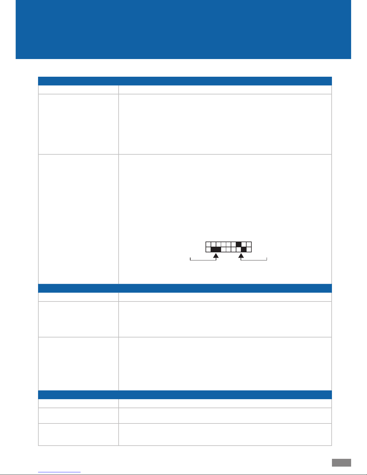
14. Troubleshooting
HEATER
Symptom Action
The PAP does not recognize the
heater. (With the PAP blower
ON, the PAP display does not
indicate Heat:xxx on the bottom line.)
Connect the heater to a known good PAP device, if one is available. If PAP display still does
not recognize the heater, replace the heater.
If a known good PAP device is not available, remove the PAP from the heater and check
the thermistor for resistance. The thermistor pins are located in the connector and are the
ones closest to each other. See image below. The resistance should be 10 K ohms +/- 1%
at 25° C (77°F). If open or shorted, replace the heater. See Service instructions. Alternatively: Replace the heater plate assembly, DV5H-607. If the resistance is in the correct range,
the issue is in the PAP device. Troubleshoot as indicated below.
Heater plate does not respond
to the PAP heat setting.
(With the PAP blower ON and
the heat setting at 1 or above,
the heater plate does not get
warm.)
Connect the heater to a known good PAP device, if one is available. If the heater still does
not respond to the heat setting, replace the heater.
If a known good PAP device is not available, connect the PAP, using the serial interface
cable DV54/DV53D-615, to a PC using a terminal program (such as Windows HyperTerminal, or equivalent) with Com settings 9600 baud, no parity, 8 data stop bits, 1 stop
bit, Flow Control set to none. Turn the PAP blower ON and increase the heat setting to
10 using the PAP keypad (UP key). In the terminal program, connect to the PAP device by
typing ‘ri’ followed by ENTER; then type ‘Ht’ followed by ENTER. Repeat the ‘Ht’ – ENTER
sequence every 2-3 minutes and verify that the returned value increases. If the value increases, the system is operating normally. If the value does not increase, remove the PAP
device from heater and measure the heater resistance. The heater terminals are the ones
diagonal to each other on the connector.
heater terminals
t
hermistor terminals
The resistance should be between 180 to 220 ohms; if not replace the heater. See Service
instructions. Alternatively: Replace the heater plate assembly, DV5H-607. If the resistance
is in the correct range, the issue is in the PAP device. Troubleshoot as indicated below.
PAP
Symptom Action
The PAP does not recognize a
known good DV5HH heater.
(With the PAP blower ON, the
PAP display does not indicate
Heat:xxx on the bottom line.)
Check the wire harness on the PAP / heater connector; repair or replace, if needed. If
the wire harness and connections are correct, replace the control PC board. See Service
Instructions.
Heater plate on a known good
DV5HH heater does not respond
to the PAP heat setting.
(With the PAP blower ON and
the heat setting at 1 or above,
the heater plate does not get
warm.)
Check the wire harness on the PAP / heater connector; repair or replace, if needed. If
the wire harness and connections are correct, replace the control PC board. See Service
Instructions.
MANIFOLD and O-RING
Symptom Action
Excessive air leak Remove the humidifi er chamber. Inspect the manifold in the heater base and replace, if
torn or worn. Inspect the O-Ring in the humidifi er chamber and replace, if worn or missing.
Water leak from the humidifi er
chamber.
Remove the humidifi er chamber. Inspect the chamber for cracks in the plastic or water leaking from the heat transfer plate. If cracks or transfer plate leaks are found, replace the water
chamber. Inspect the O-Ring in the humidifi er chamber and replace, if worn or missing.
DV5HH
Page 26
26
LT-2026
EN
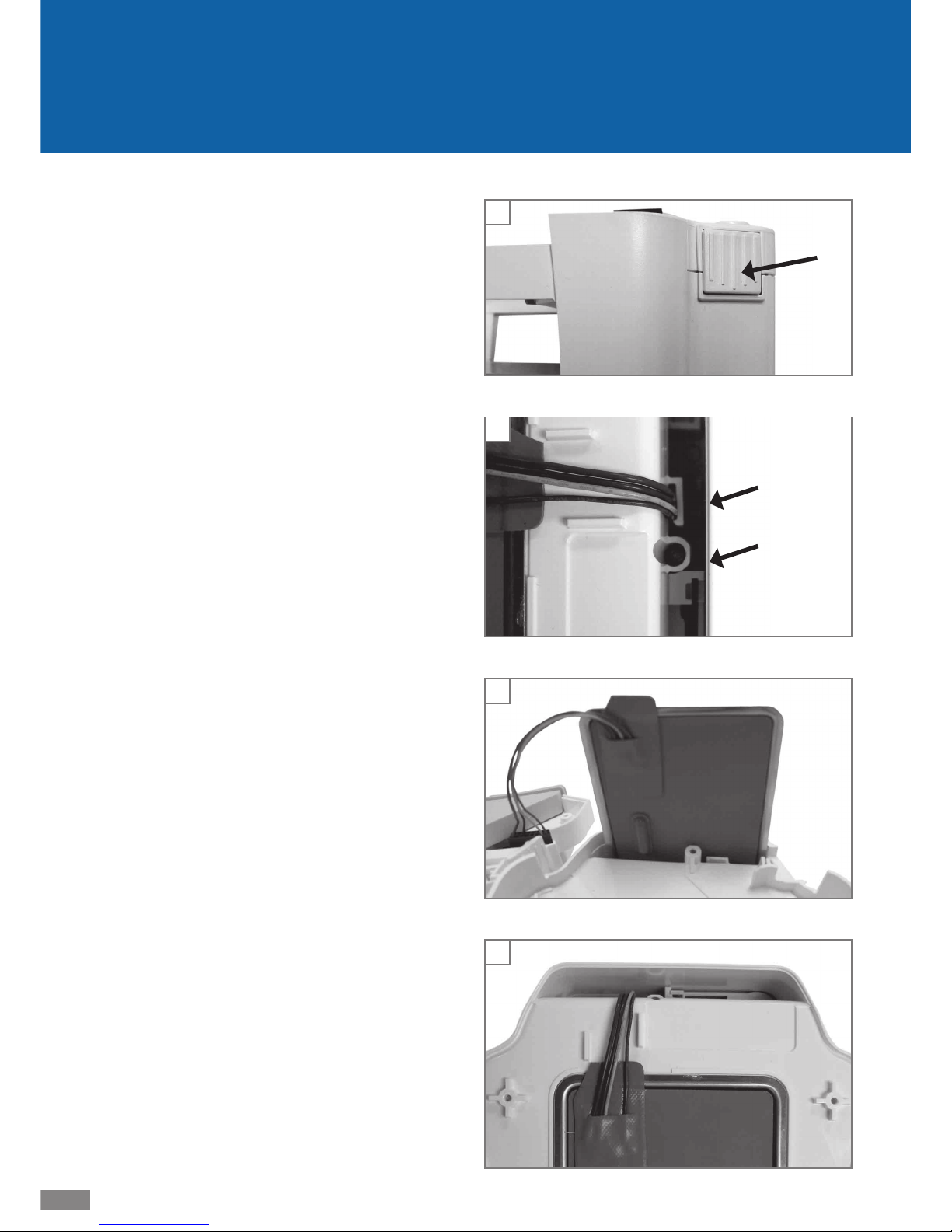
A. Removing the DV5HH base cover
1. Remove the humidifi er chamber from the DV5HH base.
2. Push the release button (Fig. 1) on the DV5HH base and
lift the PAP device off the heater base and set aside in a
safe place.
3. Remove two T-10 screws from the top cover of the heater
base.
4. Turn the base over so that the bottom of the unit faces up
and remove four T-10 screws.
5. Lift the bottom cover off the unit
6. Remove the fi nal T-10 screw beside the wire harness clip.
(Fig. 2)
7. Hold the heater plate onto the base and turn the unit over.
8. Gently pull the top of the unit off the chassis and carefully
tilt the top without pulling the wire harness out of the
connector.
9. Carefully release the wire harness from the harness clip.
Reposition the heater plate so that the orange side is facing the harness clip and carefully push the heater plate
through the opening. (Fig. 3)
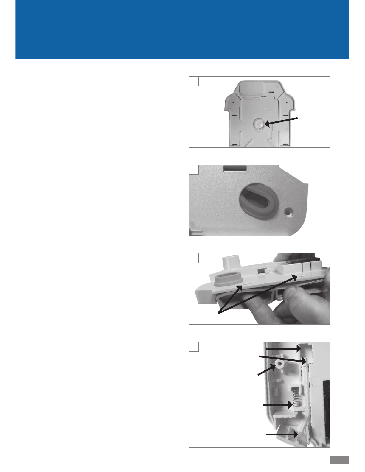
B. Replacing the DV5HH base cover
1. Position the heater plate so that the orange side is fac-
ing the harness clip and carefully push the heater plate
through the opening in the base. See image above.
2. Hold the heater plate onto the base and carefully insert
the harness wires, two at a time, into the harness clip. See
image above.
3. Install the top of the base onto the heater chassis with the
wire harness and manifold clear of all edges and the latch
working smooth and free. Fasten top to chassis with two
T-10 screws.
4. Holding the heater plate onto the base, turn the unit over
and position heater plate into the shallow opening with
the metal side facing down and the orange plastic side
facing up. Move the harness wires between wire guides.
(Fig. 4)
5. Replace the T-10 screw beside the wire harness clip.
6. Verify that the silicone spacer is in place on the inside of
the bottom cover. (Fig. 5)
7. Install the cover onto the bottom of the unit matching the
edges. Replace the 4 remaining T-10 screws in the bottom
cover.
8. With the air supply support plug attached to the back of
the PAP device, place the front of the PAP onto the front
of the heater base against the brackets and push the back
of the PAP down so that the latch closes and the electrical
connector is tight.
9. Slide the humidifi er chamber into the heater base until it
clicks into place.
DV5HH
1
harness
clip
T-10
screw
2
3
4
Page 27
LT-2026
27
EN
DV5HH
spring post
latch control
screw post
latch retainer
short leg
8
6
rattails
7
5
C. Removing and replacing silicone
manifold
1. Remove the cover as described above.
2. Squeeze the inlet port on the silicone manifold and push
the port down into the hole in the top cover, gently releasing the manifold from all other connections. Discard the
manifold or set aside in a safe place, if returning to the
unit. (Fig. 6)
3. To replace, pinch the inlet port coupler on the replacement
silicone manifold and insert it, from the inside of the cover,
through the cover hole so that the coupler collar is fully
and evenly positioned on the outside of the cover.
4. Press the manifold body into place and insert a fi nger into
each of the rectangular openings, pressing the manifold’s
rattails through the slots in the top cover until they are
fully seated. (Fig. 7)
5. Replace the cover as described above.
D. Removing and replacing the latch
1. Remove the cover and silicone manifold as described
above.
2. Raise the latch control away from the top cover so that it
lifts the attached spring. Remove the spring from the latch
and discard or set aside in a safe place, if returning it to the
unit. (Fig. 8)
3. Still holding the latch control in a raised position, push
it into the latch retainer and rotate the latch so that the
spring post faces up. Gently push the short leg of the latch
up and through the slot in the cover. Discard faulty latch.
4. Orient the replacement latch over the bottom side of the
top cover so that short leg of the latch is over the slot near
the screw post and the spring post is facing up.
5. Insert the latch into the slot by rotating the latch stem
back toward the screw post and gently applying pressure
to the short leg until it fi ts through the slot.
6. Place one end of the spring over the spring post and insert
the other end into the channel on the cover by slightly
compressing the spring. Push the latch control several
times to ensure that the system is confi gured properly.
7. Replace the silicone manifold and cover as described
above.
Page 28

28
LT-2026
EN
Humidity Output (in the operating fl ow range) ≥10 mgH2O/L air
Chamber/Cradle Dimensions
Size 2.6” H x 6.3” W x 8.4” D (6.6 cm x16.0 cm x 21.3cm)
Weight 1.75 lbs. (0.794 Kg)
Elec trical Rating:
Electrical Supply Frequency 50/60 Hz
Power Consumption 85 Watts
Voltage and Current
DV5HH 100-240VAC, 0.95 A
Heater Plate Cutout 152°C (305°F)
Power/Temperature Control Setting of 1 (minimum) to 10 (maximum)
Heater Plate Temperature approx. 29°C to approx. 65°C (84°F to 149°F)
Operating, Transport & Storage
Operating Temperature Range 41°F to 104°F (5°C to 40°C)
Operating Humidity Range 0 to 95% R.H. non-condensing
Operating Atmospheric Pressure Range 70.0 – 106.0 kPA
Transport & Storage Temperature Range -40°F to 158°F (-40°C to +70°C)
Transport & Storage Humidity Range 0 to 95% R.H. non-condensing
Transport & Storage Atmospheric Pressure Range 50.0 – 106.0 kPA
Class II Equipment; Type BF Applied Parts; Continuous Operation
IPX1, Drip-proof vertical
16. Unit Specifications DV5HH
Page 29

LT-2026
29
EN
DV54/DV53 and DV5HH
A. Ordering Non-Warranty Replacement
Parts
Order non-warranty parts and literature from your distributor
or, if you have a DeVilbiss account, from DeVilbiss Customer
Service. To expedite the process, be prepared to provide the
following information:
B. Ordering Warranty Replacement Parts
Order warranty parts from your distributor or, if you have a
DeVilbiss account, from DeVilbiss Customer Service through
the Return Material Authorization process. To expedite the
process, be prepared to provide the above information, along
with the following:
• How and where the product was being used
• A detailed description of the problem associated with
warranty replacement item
All warranty replacement orders require the return of the
defective part to DeVilbiss.
C. Returning Warranty Defective Parts
ALL DEFECTIVE PARTS, WHICH ARE STILL UNDER WARRANTY,
MUST BE RETURNED TO THE FACTORY IN SOMERSET, PA
WITHIN 30 DAYS AFTER SHIPMENT OF THE REPLACEMENT
PARTS. AN INVOICE WILL BE ISSUED IF THE DEFECTIVE PARTS
ARE NOT RECEIVED WITHIN THIS PERIOD.
D. Placing orders
Orders may be placed by calling
• Customer Service 800-338-1988
• Warranty Parts- USA 800-338-1988
• Canada 905-660-2459
• International Department 814-443-4881
Before returning parts or units to the factory, call the DeVilbiss Healthcare Customer Service Department at 800338-1988 or 814-443-4881 to obtain a return authorization
number. Include in the package a note indicating the return
authorization number along with your company name,
address, phone number, and account number. The return
authorization number should also be written on the outside
of the package.
17. Ordering and Returning Parts
• Account and ship-to numbers
• Ship-to address
• Part numbers and/or
descriptions
• Quantity required
• Unit catalog number
• Unit serial number
Page 30

30
LT-2026
EN
DV54/DV53 PAP
Air-Inlet Filter (4/pk) DV51D-602
Optional Fine Particle Filter (4/pk) DV51D-603
Air supply tubing 7351D-616
Air supply support plug DV51D-604
Disinfection kit DV51D-682
Blower assembly, balanced DV51D-672
Blower isolator and grommet-silicone DV51D-676
Foam Repair Kit DV51D-678
Tub ing Rep air Kit DV51D -6 81
Wire harness kit DV51D-675
Outlet cap (mask/leak simulator) DV51D-620
Pressure gauge with outlet cap 8000D-607
Oxygen adapter 7353D-601
Carrying case DV51D-610
IntelliPAP case repair kit-DV54/DV53 DV54D-670
SleepCube case repair kit-DV54/DV53 DV54I-670
Blower chassis DV51D-680
Keypad DV51D-671
Control PC board-DV54/DV53 DV51D-673
Power supply board-DV5X DV51D-674
LCD repair kit-DV5X DV51D-677
Heater connection cover DV51D-605
Flow control valve DV51D-621
DV5X series serial cable DV51D-615
USB to serial adapter DV51D-691
Power
AC Power cords
o USA DV51D-606
o Europe, except U.K. DV51D-607
o U.K. DV51D-608
o Australia DV51D-609
o International AC power cord set DV51D-696
DC battery clamp-on adapters DV51D-619
DC power cord DV54/
DV53D-619
DV5HH
Heated humidifi er assembly DV5HH
Humidifi er chamber DV5C
Sealing gasket for chamber DV5C-614
Silicone manifold for heater DV5H-600
Heater latch kit w/spring DV5H-601
18. Parts List
Silicone spacer on bottom cover DV5H-602
Heater bottom cover DV5H-603
Heater top cover DV5H-604
Heater chassis DV5H-605
Case screws DV5H-606
Heater assembly DV5H-607
Chamber latch spring DV5H-601
Literature
DV54/DV53 Instruction Guide
North America A-DV54/DV53
Europe / International SE-DV54/DV53
DV54/DV53 Set up Card DV54/
DV53D-125
DV54/DV53 Instructional DVD
North America LT-2012
Europe / International LT-2015
Service Manual DV54/DV53 LT-2026
Disinfection Instruction Guide A-682
Humidifi er/Heater Instruction Guide A-DV5HH
Page 31

LT-2026
31
EN
DV54/DV53
The DeVilbiss IntelliPAP™ and SleepCube™ devices are warranted to be free from defective workmanship and material
for a period of two years from date of purchase. Any defective
part(s) will be repaired or replaced at DeVilbiss’s option if the
device has not been tampered with or used improperly during
that period. Make certain that any malfunction is not due to
inadequate cleaning or failure to follow the instructions. If repair is necessary, contact your DeVilbiss provider or DeVilbiss
Customer Service Department for instructions:
U.S.A. 800-338-1988, 814-443-4881
Canada 800-263-3390
Europe 44-138-444-6688
NOTE– This warranty does not cover providing a loaner de-
vice, compensating for costs incurred in rental while said
device is under repair, or costs for labor incurred in repairing or replacing defective part(s).
THERE IS NO OTHER EXPRESS WARRANTY. IMPLIED WARRANTIES, INCLUDING THOSE OF MERCHANTABILITY AND FITNESS
FOR A PARTICULAR PURPOSE, ARE LIMITED TO THE DURATION
OF THE EXPRESS LIMITED WARRANTY AND TO THE EXTENT
PERMITTED BY LAW. ANY AND ALL IMPLIED WARRANTIES ARE
EXCLUDED. THIS IS THE EXCLUSIVE REMEDY AND LIABILITY
FOR CONSEQUENTIAL AND INCIDENTAL DAMAGES UNDER
ANY AND ALL WARRANTIES ARE EXCLUDED TO THE EXTENT
EXCLUSION IS PERMITTED BY LAW. SOME STATES DO NOT ALLOW LIMITATIONS ON HOW LONG AN IMPLIED WARRANTY
LASTS, OR THE LIMITATION OR EXCLUSION OF CONSEQUENTIAL OR INCIDENTAL DAMAGES, SO THE ABOVE LIMITATION
OR EXCLUSION MAY NOT APPLY TO YOU.
This warranty gives you specifi c legal rights, and you may also
have other rights which vary from state to state.
®Registered U.S. Patent and Trademark Offi ce and other
countries.
DV5HH
The DeVilbiss Heated Humidifi er System Model DV5HH is
warranted to be free from defective workmanship and materials for a period of two years from date of purchase (except
90 days on chamber). Any defective part(s) will be repaired or
replaced at DeVilbiss’s option if the unit has not been tampered with or used improperly during that period. Make certain that any malfunction is not due to inadequate cleaning or
failure to follow the instructions. This warranty does not cover
normal wear and tear on the o-ring seal. If repair is necessary,
contact your DeVilbiss provider or DeVilbiss Customer Service
Department for instructions:
U.S.A 800-338-1988 (814-443-4881)
Canada 905-660-2459
Europe 44-138-444-6688
NOTE– This warranty does not cover providing a loaner unit,
compensating for costs incurred in rental while said unit
is under repair, or costs for labor incurred in repairing or
replacing defective part(s).
THERE IS NO OTHER EXPRESS WARRANTY. IMPLIED WARRANTIES, INCLUDING THOSE OF MERCHANTABILITY AND FITNESS
FOR A PARTICULAR PURPOSE, ARE LIMITED TO THE DURATION
OF THE EXPRESS LIMITED WARRANTY AND TO THE EXTENT
PERMITTED BY LAW. ANY AND ALL IMPLIED WARRANTIES ARE
EXCLUDED. THIS IS THE EXCLUSIVE REMEDY AND LIABILITY
FOR CONSEQUENTIAL AND INCIDENTAL DAMAGES UNDER
ANY AND ALL WARRANTIES ARE EXCLUDED TO THE EXTENT
EXCLUSION IS PERMITTED BY LAW. SOME STATES DO NOT ALLOW LIMITATIONS ON HOW LONG AN IMPLIED WARRANTY
LASTS, OR THE LIMITATION OR EXCLUSION OF CONSEQUENTIAL OR INCIDENTAL DAMAGES, SO THE ABOVE LIMITATION
OR EXCLUSION MAY NOT APPLY TO YOU.
This warranty gives you specifi c legal rights, and you may also
have other rights which vary from state to state
19. Warranties
0044
Page 32

32
LT-2026
EN
32
LT-2026
D
Inhaltsverzeichnis – DV54/DV53
1. Allgemeine Informationen
A. Sicherheitsvorkehrungen 33
B. Erstinspektion 33
C. Transport 34
D. Gleichstromversorgung 34
E. Einstellung von Druck und Optionen 34
F. Abbildungen: DeVilbiss DV54/DV53 CPAP 34
2. Beschreibung des Normalbetriebs 35
3. Reinigung und Desinfektion 36
A. Routinemäßige Reinigungsarbeiten – Patient 36
B. Desinfektion 36
4. Technische Überprüfung und Reinigungsarbeiten 39
A. Erstinspektion 39
B. Vom Patienten durchführbare 39
routinemäßige Wartungsarbeiten
C. Wiederkehrende Geräteüberprüfung – 39
Fachhändler
5. Prüfung 40
A. Prüfung der Druckgenauigkeit 40
B. Prüfung der Flussgenauigkeit 40
C. Prüfung des Tastenfelds 40
D. Prüfung Auto-ON / Auto-OFF 41
E. Prüfung der Hintergrundbeleuchtung für 41
LCD und Tastenfeld
6. Alarmsignale und Gerätstörungen 42
A. Für den Patienten sichtbare Warnsignale 42
B. Für den Patienten sichtbare Gerätstörungen 42
C. Lesen und löschen des letzten
Störungscodes des Geräts 42
7. Kalibrierung 43
A. Manuelle Kalibrierung 43
B. Kalibrierungsfehler 44
C. Auto-Kalibrierung 44
D. Einzelheiten des seriellen Befehls “Tc” 44
8. Fehlersuche 45
9. Service-Anleitung 46
A. Abnehmen der Abdeckung 46
B. Wiederaufsetzen der Abdeckung 46
C. Entfernen der Platine 46
D. Austausch der Platine 47
E. Entfernen des Netzteils 48
F. Austausch des Netzteils 48
G. Entfernen des Gebläses 49
H. Austausch des Gebläses 49
I. Entfernen und Wiedereinsetzen des 50
Tastenfelds und des LCD
10. Technische Angaben 51
11. Allgemeines (Luftbefeuchtersystem DV5HH) 52
A. Sicherheitsvorkehrungen 52
B. Transport 52
C. Gleichstromversorgung 52
D. Produktbeschreibung 52
12. Beschreibung des Normalbetriebs (DV5HH) 53
13. Reinigung und Desinfektion (DV5HH) 54
A. Reinigung und Desinfektion 54
B. Wartung 54
C. Prüfung 54
14. Störungssuche (DV5HH) 55
15. Wartungsanleitung (DV5HH) 56
A. Entfernen der DV5HH-Sockel abdeckung 56
B. Wiederaufsetzen der DV5HH-Sockel abdeckung 56
C. Entfernen und Wiedereinsetzen 57
des Silikonverteilers
D. Entfernen und Wiedereinbau des Riegels 57
16. Technische Angaben des Geräts (DV5HH) 58
17. Bestellung und Rücksendung von Ersatzteilen
(DV51 & DV5HH) 59
A. Bestellung von Ersatzteilen, 59
auf die keine Garantie gewährt wird
B. Bestellung von Ersatzteilen, 59
auf die Garantie gewährt wird
C. Rücksendung defekter Garantieteile 59
18. Ersatzteilliste 60
A. DV54/DV53 CPAP 60
B. Stromversorgung 60
C. DV5HH 60
D. Empfohlene Masken 60
E. Literatur 60
19. Garantien 61
DV54/DV53 CPAP 61
Detaillierte EMC-Erklärung
(Elektro magnetische Verträglichkeit) 61
DV5HH 61
Page 33

LT-2026
33
EN
LT-2026
33
D
1. Allgemeine Informationen
A. Sicherheitsvorkehrungen
Bei der Verwendung von elektrischen Produkten müssen stets
grundlegende Sicherheitsvorkehrungen beachtet werden. Vor
der Verwendung dieses Geräts lesen Sie bitte die Gebrauchsanleitung. Wichtige Informationen werden durch die folgenden Begriffe angekündigt:
GEFAHR: Wichtige Sicherheitsinformationen bei Ge-
fahrenquellen, die zu ernsthaften Verletzungen oder zum Tod führen können.
WARN HINWE IS: Wichtige Sicherheitsinformationen bei Ge-
fahrenquellen, die zu ernsthaften Verletzungen führen können.
VORSICHT: Informationen zur Vermeidung von Schäden
am Gerät.
ANMERKUNG: Informationen, denen Sie besondere Auf-
merksamkeit schenken sollten.
VOR DER VERWENDUNG DIESES
GERÄTS LESEN SIE BITTE
DIE GEBRAUCHSANLEITUNG.
GEFAHR !
• Gefahr eines Elektroschocks – Das Gerät nie beim Baden
oder Duschen benutzen.
• Gefahr eines Elektroschocks – Das Gerät nie in Wasser
oder andere Flüssigkeiten eintauchen.
• Gefahr eines Elektroschocks – Versuchen Sie nie, das Ge-
rät zu öffnen oder die Gerätabdeckung abzunehmen. Das
Gerät enthält keine durch den Nutzer wartbaren Komponenten. Bei anfallenden Servicearbeiten schicken Sie das
Gerät bitte an Ihren Fachhändler zurück. Ein Öffnen des
Produkts oder unbefugte Arbeiten am Gerät führen zu
einer Außerkraftsetzung der Garantie.
WARNUNG !
• Der DeVilbiss SleepCube™ sollte ausschließlich mit Masken
benutzt werden, die von DeVilbiss, Ihrem Arzt oder einem
Beatmungstherapeuten empfohlen werden.
• Um das erneute Einatmen von ausgeatmeter Luft zu vermeiden, sollte keine CPAP-Maske verwendet werden, es sei
denn, das Gerät ist eingeschaltet und liefert Luft. Ventilationsöffnungen der Maske dürfen nie blockiert werden.
Wenn das Gerät eingeschaltet ist und Luft zuführt, wird
die Ausatemluft aus dem Auslassventil der Maske ausgeatmet. Wenn das Gerät nicht korrekt funktioniert, kann es
sein, dass die Ausatemluft erneut eingeatmet wird. Das
erneute Einatmen von Ausatemluft für länger als einige
Minuten kann unter Umständen zum Ersticken führen.
Dieser Warnhinweis gilt für die meisten CPAP-Geräte.
Der DeVilbiss SleepCube ist kein Gerät für die künstliche
Beatmung und kann bei bestimmten Funktionsstörungen
oder bei einer Unterbrechung der Stromversorgung den
Betrieb einstellen. Das Gerät ist zur Verwendung durch
spontan atmende Personen mit einem Körpergewicht von
30 kg oder mehr vorgesehen.
• Um die Gefahr eines Elektroschocks zu vermeiden, muss
das Stromkabel des Geräts bei Reinigungsarbeiten aus der
Steckdose gezogen werden.
• Bitte verwenden Sie ausschließlich Zubehörteile, die von
DeVilbiss empfohlen werden.
VORSICHT
VORSICHT: Die runde, an der Rückseite des SleepCubes
befi ndliche Datenschnittstelle ist zum Anschluss von
Zubehörteilen am Gerät vorgesehen. Dieser Anschluss darf
ausschließlich mit Zubehörteilen verwendet werden, die
von DeVilbiss empfohlen werden. Versuchen Sie nie, andere Geräte an diesem Anschluss anzuschließen, da dies zu
Schäden am CPAP oder am Zubehörteil führen kann.
VORSICHT: Gerät nie in Wasser eintauchen oder abspülen.
Achten Sie darauf, dass die Anschlüsse, Schalter oder der
Luftfi lter nie mit Flüssigkeiten in Kontakt kommen, da dies
zu Schäden am Gerät führt. In derartigen Fällen muss der
Einsatz des Geräts sofort beendet und das Stromkabel des
Geräts aus der Steckdose gezogen werden. Lassen Sie das
Gerät vor dem nächsten Einsatz völlig trocknen.
VORSICHT: Achten Sie darauf, dass der SleepCube nie an Orten aufgestellt wird, an denen er umgestoßen werden könnte
oder wo man über das Stromkabel stolpern kann.
VORSICHT: Mit dem SleepCube und dem SleepCube wird ausschließlich die Verwendung von beheizten Luftbefeuchtern
der DV5-Serie von DeVilbiss empfohlen. Der Einsatz anderer
Luftbefeuchter-Systeme kann zu einer Störung der Erkennung
des Schnarchens durch das Gerät und damit zu einem unangemessenen Druck in der Maske führen.
VORSICHT: Sauerstoff ist ein verschreibungspfl ichtiges Gas
und sollte ausschließlich von einem Arzt ver abreicht werden.
B. Erstinspektion
DeVilbiss empfi ehlt eine Inspektion des Geräts sofort nach
der Lieferung.
• Schließen Sie das DV54/DV53 CPAP an eine Netzsteckdose
an.
• Prüfen Sie die Druckgenauigkeit mithilfe eines Ausgangsverschlusses (DV54/DV53D-620), eines kalibrierten Druckmessgeräts und den unter „Prüfung der Druckgenauigkeit” aufgelisteten Verfahren.
Page 34

34
LT-2026
EN
34
LT-2026
D
F. Abbildungen: DeVilbiss DV54/DV53
CPAP
Abbildungen A und B: DV54/DV53 Rück- und Unterseite des
Geräts
1. Schlauchanschluß an der Rückseite des Geräts
2. Luftzufuhr an der Unterseite des Geräts für den optionalen Luftbefeuchter
3. Verschlußkappe
4. Stromanschluss für den optionalen Luftbefeuchter
5. Wechselstromanschluss (≈)
6. Gleichstromanschluss (=)
7. Datenschnit tstell e
8. Öffnung für Lufteinlassfi lter
Abbildung C: Tastenfeld
1. EIN/AUS (ON/OFF)
2. Vorhergehende Position
3. Nächste Position
4. Verzögerung
5. Wert herabsetzen
6. Wert erhöhen
7. LED für die Stromzufuhr der Beheizung (für optionalen
Luftbefeuchter)
C
5
1
2
4
6
3
7
B
2
4
A
1
3
56 7
8
• Prüfen Sie die Tasten des Tastenfelds mithilfe der unter
“Prüfung des Tastenfelds” angegebenen Verfahren.
C. Transport
Der DeVilbiss DV54/DV53 CPAP
• Passt sich automatisch an Höhen zwischen Meereshöhe
und 2750 m an.
• Stellt sich automatisch auf Spannungen zwischen 100-240
V, 50-60 Hz ein.
• Benötigt ein den Vorschriften des jeweiligen Landes entsprechendes Stromkabel.
o USA DV54/DV53D-606
o Europa mit Ausnahme von GB DV54/DV53D-607
o GB DV54/DV53D-608
o Australien DV54/DV53D-609
D. Gleichstromversorgung
Der DeVilbiss DV54/DV53 CPAP:
• Stellt sich automatisch auf eine 12 V Gleichstromversorgung ein. Arbeitet nur dann mit Gleichstrom, wenn kein
Wechselstrom anliegt. Arbeitet mit Wechselstrom, wenn
sowohl Gleichstrom als auch Wechselstrom anliegen.
• Optionaler Transformator von Gleichstrom zu Wechselstrom: Mindestens 200 Watt bei 100/120 V ≈.
Mindestens 400 Watt bei 220 V ≈
• Geeignetes Gleichstromkabel
o DV54/DV53D-619 Gleichstromzubehörkabel für
einsteckbare Gleichstromadapter
o DV54/DV53D-696 An die Gleichstrombatterie anklemmbarer Adapter für allein stehende Batterien
E. Einstellung von Druck und Optionen
Befolgen Sie die folgenden Arbeitsschritte zur Eingabe des
Klinik- / Einstellungsmodus:
1. Schließen Sie das Wechselstromkabel an das Gerät an.
2. Überzeugen Sie sich, dass das LCD „AUS“ anzeigt.
3. Halten Sie die Tasten “Pfeil nach unten” und „Verzögerung“ gedrückt.
4. Während Sie diese beiden Tasten gedrückt halten, drücken
Sie die Taste „EIN/AUS“.
5. Das Gebläse beginnt zu arbeiten und das LCD zeigt das
“Klinik-Menü” (Clinical Menu) an.
6. Benutzen Sie die Tasten “Pfeil nach rechts” und “Pfeil nach
links”, um durch die Optionen zu blättern.
7. Benutzen Sie die Tasten “Pfeil nach oben” und “Pfeil nach
unten”, um den Wert der Option zu wählen.
8. Drücken Sie die Taste „EIN/AUS“, um das Klinik-Menü zu
verlassen.
Page 35

LT-2026
35
EN
LT-2026
35
D
Ein Wechselstromkabel (100-240 V WS, 50/60 Hz) oder ein
Gleichstromkabel (12 V GS) sorgt für die Stromzufuhr zum
DV54/DV53 PAP. Der PAP wandelt die Wechselstromeingangsspannung durch eine innere schaltbare Stromversorgung auf
Gleichstrom um und verwendet diesen Gleichstrom zur Versorgung der internen Elektronikkomponenten des Geräts, wie
z. B. Mikro-Controller, Schaltkreise der Motorsteuerung, Gebläse,
LCD-Anzeige etc. ANMERKUNG: Der beheizte Luftbefeuchter
funktioniert nicht, wenn am PAP externer Gleichstrom anliegt.
Der PAP liefert Überdruck durch Rotation eines rückwärts
geformten Impellers mit Gleichstromantrieb ohne Kohleelektroden. Durch einen Filter wird Umgebungsluft in das
Gebläse angesaugt, im Gebläse verdichtet, dann wahlweise
durch eine beheizte Luftbefeuchterkammer geleitet und
durch einen glatten Schlauch mit 22 mm Innendurchmesser
ausgelassen. Die Druckregulierung erfolgt durch Feedback
von der Druck- und Flussmessung.
Der DV54/DV53 PAP überwacht die Atmung des Patienten
über ein Monitoring des Flusswandlersignals, das die durch Einund Ausatmung verursachten Schwankungen wahrnimmt.
Das Flusswandlersignal löst darüber hinaus die Warnsignale
„Mask-OFF“ (Maske ab) und die Auto-EIN / Auto-AUS-Funktionen
aus.
Im Modus „Automatische Einstellung“ analysiert die Software
des DV54/DV53 das Signal vom Flusswandler, um die durch die
programmierbaren Einstellungen vorgegebenen respiratorischen Ereignisse wie Apnoen, Hypopnoen, gemischte Apnoen,
Schnarchen und Ausstoßen von Atemluft durch geschlossene
Lippen wahrzunehmen. Über einen Onboard-Algorithmus
werden die wahrgenommenen respiratorischen Ereignisse
bewertet und der Luftdruck wie folgt angepasst: Der DV54/
DV53 PAP erhöht den Auslassdruck, wenn Apnoen, Hypopnoen
und Schnarchen wahrgenommen werden, das Gerät hält den
Druck aufrecht, wenn gemischte Ereignisse verzeichnet werden
und senkt den Druck in regelmäßigen zeitlich festgelegten
Intervallen, wenn die Anzahl der jüngsten respiratorischen
Ereignisse abnimmt.
2. Beschreibung des Normalbetriebs
Page 36

36
LT-2026
EN
36
LT-2026
D
3. Reinigung und Desinfektion
A. Vom Patienten durchführbare
routinemäßige Reinigungsarbeiten
• Ziehen Sie den Stecker des DV54/DV53 CPAP aus der
Steckdose und wischen Sie das Gehäuse alle paar Tage mit
einem sauberen feuchten Tuch ab, um das Gerät staubfrei
zu halten. Lassen Sie das Gerät völlig trocknen, bevor Sie
den Stecker wieder in die Steckdose stecken.
• Prüfen Sie den Lufteinlassfi lter alle 10 Tage. Waschen Sie
den dunklen äußeren Schaumstofffi lter in einer Lösung
aus warmem Wasser und einem milden Spülmittel.
Spülen Sie den Filter und lassen Sie ihn völlig austrocknen,
bevor Sie ihn wieder einsetzen.
• Prüfen Sie alle 10 Tage den optionalen Partikelfi lter und
tauschen Sie ihn bei Bedarf (verschmutzt oder beschädigt)
aus.
• Reinigen Sie den Luftzufuhrschlauch jeden Tag. Nehmen
Sie den Schlauch vom Gerät und von der Maske ab und
spülen Sie ihn mit einer Lösung aus warmem Wasser und
einem milden Spülmittel gründlich aus. Spülen Sie den
Schlauch mit Wasser nach und lassen sie ihn an der Luft
trocknen, bevor Sie den Schlauch wieder an das Gerät und
die Maske anschließen.
• Reinigen Sie die Maske und die Kopfgurte im Einklang mit
den Anweisungen des Herstellers.
B. Desinfektion
VORSICHT: Arbeiten Sie immer in einem Umfeld, das vor elek-
trostatischen Entladungen sicher ist, wenn Sie elektronische
Komponenten auseinander nehmen oder wieder zusammensetzen
ANMERKUNG: DeVilbiss verlangt keine Desinfektion als Teil
der Gerätwartung. Wird eine Desinfektion gewünscht, empfehlen wir folgende Vorgehensweise:
ANMERKUNG: Die zur Durchführung einer Desinfektion benötigten Teile werden durch die in diesem Handbuch aufgeführte DV54/DV53 CPAP-Garantie NICHT abgedeckt.
ANMERKUNG: Befolgen Sie die Anweisungen des Herstellers
zur Verwendung von Reinigungs- und Desinfektionslösungen.
ANMERKUNG: Zur Desinfektion benötigen Sie die folgenden
Teile, die als Desinfektionssatz erworben werden können:
DV54/DV53D-682.
• Gebläsebaugruppe, austariert Schlauch/Stecker für Luftzufuhr des Luftbefeuchters
• Gebläseisolator-Silikon
• 1,3 cm Gebläsebefestigung aus Schaumstoff - rund
• Ring - Silikon
• 1,3 cm Einlass-Schaumstoff
• 0,85 cm Schaumstoff Gebläseumhüllung
• Schaumstoff 0,42 cm in der unteren Abdeckung
• 9 cm Silikonschlauch
• 12,7 cm Silikonschlauch
• Lufteinlassfi lter
• Feinpartikelfi lter
• 14 cm Silikonschlauch – entsorgen, wird für dieses Modell
nicht benötigt
Desinfektion des SleepCube CPAP
1. Achten Sie darauf, dass das Gerät nicht an eine Stromquelle
angeschlossen ist.
2. Falls erforderlich, müssen Maske, Kopfgurte, Luftzufuhrschlauch, Grobluftfi lter aus grauem Schaumstoff und
weißer Feinpartikelfi lter entsorgt werden.
3. Stellen Sie das Gerät mit der Unterseite nach oben auf
eine saubere Arbeitsfl äche. Entfernen Sie die vier Schrauben aus der unteren Abdeckung und nehmen Sie diese
Abdeckung vom Gerät ab (Abb. 1).
4. Entfernen Sie den schwarzen, 0,3 cm dicken Schaumstoff
aus der unteren Abdeckung und entsorgen Sie ihn. Es ist
möglich, dass dieser Schaumstoff an der Grundplatte des
Geräts anhaftet (Abb. 2).
5. Entfernen Sie den 1,3 cm dicken Einlassschaumstoff von
der Grundplatte des Geräts und entsorgen Sie ihn.
6. Drehen Sie das Gerät um und nehmen Sie die obere Abdeckung ab.
7. Entfernen Sie mithilfe eines T-15 Schraubenziehers die
Schraube, mit der die Platine an der Grundplatte befestigt
ist (Abb. 3).
8. Ziehen Sie den Kabelstrang mit den acht Anschlüssen des
Gebläses von der Unterseite der Platine ab (Abb. 4).
9. Entfernen Sie die beiden Schlauchstücke und entsorgen
Sie diese (Abb. 5).
ANMERKUNG: Ziehen Sie die Schlauchstücke gerade von
den Anschlüssen ab, um Schäden an der Grundplatte zu
vermeiden. Entfernen Sie die Schlauchstücke und entsorgen Sie sie.
10. Achten Sie darauf, dass die Seite der Grundplatte mit den
Anschlüssen zu Ihnen zeigt. Kippen Sie die Platine und
ihren Kabelstrang nach oben und entfernen Sie die Kabelanschlüsse. (Abb. 6).
Page 37

LT-2026
37
EN
LT-2026
37
D
41
3
2 5
6
Page 38

38
LT-2026
EN
38
LT-2026
D
7
8
9
10
11
11. Entfernen Sie den Ring, der die Dichtung für den Kabelstrang des Gebläses bildet (Abb. 7).
12. Entfernen Sie den Kabelanschluss des Heizteils durch
Schieben des Anschlusses nach außen und leichtes Ziehen
der oberen Haltelasche nach oben von der Unterseite der
Grundplatte. (Abb. 8).
13. Entfernen Sie die 0,6 cm dicke Schaumstoffhülle des Gebläses, das Gebläse selbst und den Silikonisolator von der
Unterseite der Grundplatte.
14. Der Lufteinlass, der Luftweg und beide Gehäusehälften
innen und außen müssen sorgfältig mit einer 2%-igen
Glutaraldehydlösung eingesprüht, abgewischt oder darin
eingeweicht werden.
15. Wischen Sie das Stromkabel und die Außenseite beider
Hälften des CPAP-Gehäuses mit der selben Lösung ab.
16. Lassen Sie alle Komponenten gründlich trocknen.
17. Bauen Sie das Gerät wieder mit den Teilen aus dem Desinfektionssatz DV54/DV53D-682 zusammen.
ANMERKUNGEN:
o Verlegen Sie den Silikonschlauch korrekt wie in der Ab-
bildung 9 dargestellt und achten Sie darauf, dass keine
Knicke entstehen.
o Achten Sie darauf, dass der Silikonisolator korrekt auf der
Grundplatte und am Gebläse sitzt.
o Achten Sie darauf, dass der Ring korrekt um den Kabel-
strang des Gebläses sitzt.
o Den Kabelstrang mithilfe der beiliegenden Kabelhalter auf
der Grundplatte verlegen. (Abb. 10 + 11)
o Sichern Sie das Netzteil in den Befestigungsclips an der
Grundplatte, bevor Sie die Abdeckungen wieder anbringen. (Abb. 10)
Page 39

LT-2026
39
EN
LT-2026
39
D
4. Technische Überprüfung und Reinigungsarbeiten
A. Eingangskontrolle – Fachhändler
DeVilbiss empfi ehlt eine technische Kontrolle des Geräts
sofort nach der Lieferung.
• Schließen Sie den DV54/DV53 CPAP an eine Netzsteckdose an.
• Prüfen Sie die Druckgenauigkeit mithilfe eines Ausgangsverschlusses (DV54/DV53D-620), eines kalibrierten
Druckmessgerätes und den unter „Prüfung der Druckgenauigkeit“ aufgelisteten Verfahren.
• Prüfen Sie die Tasten des Tastenfelds mithilfe der unter
„Prüfung des Tastenfelds“ angegebenen Verfahren.
B. Vom Patienten durchführbare
routinemäßige Reinigungsarbeiten
• Wischen Sie das Gehäuse im Abstand von einigen Tagen
mit einem feuchten Tuch ab.
• Prüfen Sie alle 10 Tage den Lufteinlassfi lter und reinigen
Sie ihn je nach Bedarf.
• Reinigen Sie jeden Tag den Luftzufuhrschlauch.
• Reinigen Sie die Maske und die Kopfgurte im Einklang mit
den Anweisungen des Herstellers.
C. Wiederkehrende Geräteüberprüfung –
Fachhändler
Zur Erhaltung der Produkteigenschaften ist die nachfolgende
Geräteüberprüfung regelmäßig alle 3 Jahre durchzuführen:
• Prüfen Sie die Druckgenauigkeit mithilfe der unter
„Prüfung der Druckgenauigkeit“ aufgelisteten Verfahren.
• Muss das Gerät kalibriert werden, befolgen Sie die
aufgelisteten Korrekturverfahren.
• Zeigen Sie dem Patienten die notwendigen Kontrollen
der Filter wie in der Anleitung beschrieben:
Standardfi lter & Optionaler Feinpartikelfi lter
o Tägliche Überprüfung des Filters
o Ein verschmutzter Filter muss ausgetauscht werden.
o Austausch des Standardfi lters spätestens alle sechs Monate.
o Austausch des Feinpartikelfi lters alle 30 Tage.
Mithilfe der folgenden Testverfahren muss der korrekte Betrieb des DV54/DV53 CPAP geprüft werden. Diese Ver fahren
sollten auch an allen reparierten Geräten zur Anwendung
kommen.
ANMERKUNG: Überzeugen Sie sich, dass das DV54/DV53
CPAP mit der neuesten Firmware-Version arbeitet, bevor Sie
Wartungs- oder Reparaturarbeiten durchführen. Siehe http://
www.devilbisshealthcare.com/Products für Downloads der
neuesten Firmwareversionen. Download- und Installationsanweisungen können auf der Website eingesehen werden.
Page 40

40
LT-2026
EN
40
LT-2026
D
5. Prüfung
A. Prüfung der Druckgenauigkeit
Erforderliche zusätzliche Geräte: Auslassverschluss (DV54/
DV53D-620), kalibriertes Druckmessgerät (0-30 cmH2O, Genauigkeit ±0,25 cmH2O)
1. Schließen Sie das Druckmessgerät an den Schlauchanschluß des Geräts an.
2. Schließen Sie das Wechselstromkabel an das Gerät an.
Wenn das Gebläse läuft, drücken Sie die Taste „EIN/AUS“
auf dem Tastenfeld, um das Gebläse zu stoppen. Das LCD
zeigt „AUS“.
3. Während Sie die Tasten “Pfeil nach unten” und „Verzögerung“ gedrückt halten, drücken Sie die Taste „EIN/AUS“, um
das Gebläse zu starten und in den Klinikmodus zu gelangen.
4. Drücken Sie die Taste „Nächster Posten“ (Pfeil nach rechts),
um in den Bildschirm für den Betriebsmodus zu gelangen.
Drücken Sie die Tasten „Pfeil nach oben“ oder „Pfeil nach
unten“, um das Gerät in den CPAP-Modus zu bringen.
5. Drücken Sie die Taste „Nächste Position“, bis der eingestellte Druck angezeigt wird. Benutzen Sie die Tasten “Pfeil
nach oben” und “Pfeil nach unten”, um den Druck auf 12
cmH2O einzustellen. Warten Sie mindestens 30 Sekunden,
damit sich der Druck stabilisieren kann.
6. Überzeugen Sie sich, dass der angezeigte Druck dem
auf dem Druckmessgerät angezeigten Druck entspricht
(Druckeinstellung ±1,0 cmH2O). Die Druckgenauigkeit
kann bei Bedarf auch bei anderen Druckeinstellungen
geprüft werden.
7. Wenn der Druck kalibriert werden muss, schalten Sie das
Gebläse für ca. 1 Minute AUS, damit die Auto-Kalibrierung
ablaufen kann. Schalten Sie das Gebläse wieder EIN, und
warten Sie 30 Sekunden, damit sich der Druck stabilisieren
kann. Entspricht der Druck immer noch nicht der Kalibrierung, muss mithilfe des manuellen Kalibrierungsverfahren
eine vollständige Kalibrierung durchgeführt werden.
8. Lässt sich die Druckgenauigkeit nicht durch die manuelle
Kalibrierung verbessern, kann eine Störung des Flussweges
oder der Steuerplatine vorliegen. Siehe “Störungssuche”.
B. Prüfung der Flussgenauigkeit
Erforderliche zusätzliche Geräte: Kabel PAP an PC (DV51D-615),
ein kalibrierter volumetrischer Massenfl ussmesser (Bereich 0
bis 150 l/min., Genauigkeit ± 3 l/min.), ein Flusskontrollventil
DV51D-621 zur Einstellung des Luftfl usses sowie ein TerminalProgramm (z. B. Microsoft Windows HyperTerminal).
1. Führen Sie zunächst die Prüfung der Druckgenauigkeit
durch, um zu gewährleisten, dass der Druck korrekt ist.
2. Schließen Sie den volumetrischen Massenfl uss-Messer
und das Flusskontrollventil an den Auslassport des Geräts
an und schließen Sie das Ventil.
3. Stecken Sie das Netzkabel des Geräts in eine Netzsteckdose und schließen Sie das Gerät über das PAP an PC-Kabel
an das Terminal-Programm an.
4. Wenn das Gebläse läuft, drücken Sie die Taste „EIN/AUS“
auf dem Tastenfeld, um das Gebläse zu stoppen. Das LCD
zeigt „AUS“.
5. Während Sie die Tasten „Pfeil nach unten“ und „Delay“
(Verzögerung) gedrückt halten, drücken Sie die Taste
„EIN/AUS“, um das Gebläse zu starten und in den Klinikmodus zu gelangen.
6. Drücken Sie die Taste „Nächster Posten“ (Pfeil nach rechts),
um in den Bildschirm für den Betriebsmodus zu gelangen.
Drücken Sie die Tasten „Pfeil nach oben“ oder „Pfeil nach
unten“, um das Gerät in den CPAP-Modus zu bringen.
7. Drücken Sie die Taste „Next Item“ (Nächster Posten), bis
der eingestellte Druck angezeigt wird. Benutzen Sie die
Tasten „Pfeil nach oben“ und „Pfeil nach unten“, um den
Druck auf 12 cmH2O einzustellen. Warten Sie mindestens
30 Sekunden, damit sich der Druck stabilisieren kann.
8. Stellen Sie das Flusskontrollventil so ein, dass der Flussmesser 60 l/min. anzeigt. Warten Sie mindestens 30 Sekunden,
bis sich der Fluss stabilisiert hat.
9. Prüfen Sie, dass der Leckagefl uss(Terminal-Befehl:FI) dem
auf dem Flussmesser angegebenen Wert entspricht
(eingestellter Wert ± 10 l/min.). Je nach Bedarf kann die
Genauigkeit bei anderen Flusseinstellungen geprüft werden.
10. Muss der Fluss kalibriert werden, schalten Sie das Gebläse
für ca. 1 Minute AUS, damit die Auto-Kalibrierung ablaufen
kann. Schalten Sie das Gebläse wieder EIN und warten
Sie 30 Sekunden, damit sich Druck und Fluss stabilisieren
können. Liegen die Flusswerte immer noch außerhalb der
Kalibrierungsgrenzen, muss eine vollständige Kalibrierung
mithilfe des manuellen Kalibrierungsverfahren durchgeführt werden.
11. Wenn die Flussgenauigkeit nicht durch die manuelle Kalibrierung verbessert wird, kann eine Störung des Flusswegs
oder der Steuerkarte vorliegen. Siehe „Störungssuche“.
Page 41

LT-2026
41
EN
LT-2026
41
D
C. Prüfung des Tastenfelds
Keine zusätzlichen Geräte erforderlich.
1. Schließen Sie das Wechselstromkabel an das Gerät an.
Wenn das Gebläse läuft, drücken Sie die Taste „EIN/AUS“
auf dem Tastenfeld, um das Gebläse zu stoppen. Das LCD
zeigt „AUS“.
2. Während Sie die Tasten “Pfeil nach unten” und „Verzögerung“ gedrückt halten, drücken Sie die Taste „EIN/AUS“, um
das Gebläse zu starten und in den Klinikmodus zu gelangen.
3. Drücken Sie die Taste „Nächste Position“, bis die Verzögerungszeit auf dem LCD angezeigt wird.
4. Achten Sie auf die Verzögerungszeit; ändern Sie danach
die Verzögerungszeit durch Drücken der Tasten “Pfeil nach
oben” und “Pfeil nach unten”. Verwenden Sie die Pfeiltasten, um die Verzögerungszeit wieder auf den ursprünglichen Wert einzustellen.
5. Verwenden Sie die Taste „Vorhergehende Position“, um
wieder in den Druckeinstellungsbildschirm zu gelangen.
6. Wenn im Verlauf dieser Prüfung eine oder mehrere Tasten
des Tastenfelds nicht korrekt funktionierten, tauschen Sie
die Platine mithilfe der Service-Anleitung aus.
D. Prüfung Auto-ON (Auto-EIN) /
Auto-OFF (Auto-AUS)
Erforderliche zusätzliche Geräte: Schlauch mit glatter Innenoberfl äche (3 m lang, 22 mm dick).
1. Schließen Sie das Wechselstromkabel an das Gerät an.
Wenn das Gebläse läuft, drücken Sie die Taste „EIN/AUS“
auf dem Tastenfeld, um das Gebläse zu stoppen. Das LCD
zeigt „AUS“.
2. Während Sie die Tasten “Pfeil nach unten” und „Verzögerung“ gedrückt halten, drücken Sie die Taste „EIN/AUS“, um
das Gebläse zu starten und in den Klinikmodus zu gelangen.
3. Drücken Sie die Taste „Nächste Position“, bis das Aktivierungs-Menü angezeigt wird. Drücken Sie dann die Taste
“Pfeil nach unten”, um in das Unter-Menü zu gelangen.
4. Drücken Sie die Taste „Nächste Position“, bis die Einstellung Auto-EIN angezeigt wird. Verwenden Sie die Tasten
“Pfeil nach oben” oder “Pfeil nach unten”, um den Wert
auf „Aktiviert“ einzustellen.
5. Drücken Sie die Taste „Nächste Position“, bis die Einstellung “Auto-OFF” (Auto-AUS) angezeigt wird. Verwenden
Sie die Tasten “Pfeil nach oben” oder “Pfeil nach unten”,
um den Wert auf „Aktiviert“ einzustellen.
6. Drücken Sie die Taste „EIN/AUS“, um das Gebläse zu
stoppen. Das LCD zeigt „AUS“.
7. Schließen Sie den CPAP-Schlauch an das CPAP-Gerät an
und blockieren Sie den Luftfl uss mit Ihrer Hand oder
einem Verschluss.
8. Schalten Sie das Gebläse durch Drücken der Taste „EIN/
AUS“ auf dem Tastenfeld ein.
9. Halten Sie den Luftfl uss für zwei Minuten blockiert. Überzeugen Sie sich, dass das Gebläse weiterläuft und dass
keine Masken-Warnsignale erscheinen.
10. Öffnen Sie den CPAP-Schlauch, damit die Luft wieder
fl ießen kann.
11. Überzeugen Sie sich, dass das LCD nach etwa 10 Sekunden
anzeigt “Mask OFF” (Maske AB). Wenn das Masken-Warnsignal nicht erscheint, gehen Sie zu Arbeitsschritt 14 über.
12. Das Gebläse muss sich nach ca. 20 Sekunden über AutoOFF ausschalten. Warten Sie etwa zwei Minuten, nachdem sich das Gebläse ausgeschaltet hat. Überzeugen Sie
sich, dass sich das Gebläse nicht ohne Atmung wieder
einschaltet.
13. Verschließen Sie als Simulation der Atmung das Ende
des Schlauches in kurzen Abständen mit Ihrer Hand und
überzeugen Sie sich, dass das Gebläse über die Auto-ONFunktion wieder einschaltet.
14. Sollten die Auto-OFF- oder Auto-ON-Funktionen nicht
korrekt funktionieren, muss mithilfe des manuellen
Kalibrierungsverfahrens eine vollständige Kalibrierung
vorgenommen werden.
E. Prüfung der Hintergrundbeleuchtung
für LCD und Tastenfeld
Keine zusätzlichen Geräte erforderlich.
1. Schließen Sie das Wechselstromkabel an das Gerät an.
Wenn das Gebläse läuft, drücken Sie die Taste „EIN/AUS“
auf dem Tastenfeld, um das Gebläse zu stoppen. Das LCD
zeigt „AUS“.
2. Drücken Sie die Taste „EIN/AUS“ und überzeugen Sie sich,
dass die Hintergrundbeleuchtung von LCD und Tastenfeld
aufl euchtet.
3. Warten Sie eine Minute und überzeugen Sie sich, dass
die Helligkeit der Hintergrundbeleuchtung von LCD und
Tas tenfeld ab nim mt.
4. Drücken Sie eine Taste des Tastenfelds (mit Ausnahme von
“ON/OFF”) und überzeugen Sie sich, dass die Helligkeit der
Hintergrundbeleuchtung von LCD und Tastenfeld wieder
auf voller Stärke ist.
5. Sollte die Hintergrundbeleuchtung von LCD oder Tasten-
feld im Verlauf dieses Tests nicht korrekt funktionieren,
muss das LCD, das Tastenfeld und/oder die Platine ausgetauscht werden.
Page 42

42
LT-2026
EN
42
LT-2026
D
6. Alarmsignale und Gerätstörungen
A. Für den Patienten sichtbare
Warnsignale
Warnsignal Beschreibung
Verzögerter Betrieb
noch XX Minuten
(Delay running
XX minutes left)
Rampe aktiv – Anzeige der
verbleibenden Rampenzeit
LECK AN DER MASKE = XX%.
PASSUNG PRÜFEN.
Hoher Luftfluss für mindestens
10 % der vorhergehenden
Nutzungszeit (schlechte
Masken passung) (tatsächlicher
Prozentsatz wird aufgeführt)
Maske ab. Bitte Maskenpassung prüfen
(Mask off. Please check
mask fi t.)
Starker Leckage bei der
Verwendung (Schlechte
Maskenpassung oder Maske
abgenommen)
Device Fault E0X. Call
provider.
(Gerätstörung E0X.
Fachhändler anrufen)
Gerätstörung
(Siehe nächste Tabelle).
B. Für den Patienten sichtbare
Gerätstörungen
Nur die als kritisch klassifi zierten Gerätstörungen sind auf
dem LCD für den Patienten sichtbar. Diese Störungen können
durch einen Service-Techniker behoben werden.
Gerät-
störung
Störung Beschreibung
E01
Ablesen der Einstellung Die gespeicherten
Verschreibungswerte sind korrumpiert. Das
Gerät befi ndet sich in einem störungssicheren
Zustand (Gebläse aus), wenn diese Störung
angezeigt wird. Zur Korrektur der Störung siehe
“Störungssuche” und “Service-Anleitung” oder
schicken Sie das Gerät zur Reparatur zurück.
E03
Motorstörung Das Gerät versucht, den Motor
zu betreiben, aber das Gebläse dreht sich nicht
(Motorgeschwindigkeit Null). Zur Korrektur der
Störung siehe “Störungssuche” und “ServiceAnleitung” oder schicken Sie das Gerät zur
Reparatur zurück.
E04
Störung gesperrter Rotor Die durchschnittliche
Motorgeschwindigkeit ist niedrig trotz hoher,
mehrere Sekunden dauernder Stromaufnahme
durch den Motor. Zur Korrektur der Störung
siehe “Störungssuche” und “Service-Anleitung”
oder schicken Sie das Gerät zur Reparatur
zurück.
E06
Motorlaufstörung Hohe Motorgeschwindigkeit und Druck und Gesamtfl uss sind für einen
bestimmten Zeitraum niedrig (in der Nähe
von Null). Zur Korrektur der Störung siehe
„Störungssuche” und „Service-Anleitung” oder
schicken Sie das Gerät zur Reparatur zurück
E07
Störung Motordefekt Die Meldung des MotorKontrollchips wird für einen festen Zeitraum
aktiv erniedrigt. Zur Korrektur der Störung siehe
“Störungssuche” und “Service-Anleitung” oder
schicken Sie das Gerät zur Reparatur zurück.
C. Lesen und löschen des letzten
Störungscodes des Geräts
ANMERKUNG: Der letzte Störungscode des Geräts wird im
EPROM gespeichert, um den Service des Geräts im Feld zu
erleichtern.
Zusätzliche Geräte: IBM- oder IBM-kompatibler PC mit freier
serieller Schnittstelle, PC-Kabel (DV54/DV53D-615), ein
Terminal-Programm (Microsoft Windows HyperTerminal oder
entsprechend).
1. Schließen Sie das DV54/DV53 CPAP mit einem PC-Kabel an
die serielle Schnittstelle des PC an.
2. Schließen Sie das Wechselstromkabel an das Gerät an.
Wenn das Gebläse läuft, drücken Sie die Taste „EIN/AUS“
auf dem Tastenfeld, um das Gebläse zu stoppen. Das LCD
zeigt „AUS“.
3. Verwenden Sie ein Terminal-Programm (wie z. B. Windows
HyperTerminal oder entsprechend) mit COM-Einstellung
9600 Baud, keine Parität, 8 Datenbits, 1 Stop-Bit und Flusskontrolle eingestellt auf “Keine”.
4. Wenn die Verbindung mit dem CPAP hergestellt ist, zeigt
das Terminal-Programm: “RI;” alle 0,5 Sekunden. Das
Display zeigt an, dass das Gerät auf einen “Handshake”
wartet.
5. Geben Sie “ri” ein (achten Sie dabei auf Groß- und Kleinschreibung) und drücken Sie auf „Enter“. Das CPAP müsste
mit der Firmware-Version in der Form “V0.XX MM/TT/JJJJ”
antworten. Wiederholen Sie bei Bedarf diesen Arbeitsschritt, um den “Handshake” abzuschließen.
6. Forden Sie den letzten Warnsignal-Code mit Datum durch
Eintippen von “EI” und Drücken von „Enter“. Der gelieferte Wert hat das Format “Exx TT/MM/JJJJ”. Exx ist der
Warnsignal-Code und TT/MM/JJJJ ist das Datum, an dem
die Störung aufgetreten ist.
7. Löschen Sie den letzten Warnsignal-Code durch Eintippen
von “Ec” und Drücken von „Enter“. Das CPAP antwortet
mit “OK”.
Page 43

LT-2026
43
EN
LT-2026
43
D
7. Kalibrierung
A. Manuelle Kalibrierung
DeVilbiss empfi ehlt die Kalibrierung des DV54/DV53 CPAP,
wenn die Platine ausgetauscht wurde oder wenn als Teil einer
Prüfung oder Störungssuche angezeigt wird, dass eine Kalibrierung erforderlich ist. Das manuelle Kalibrierungsverfahren
greift über den Kommunikationsschnittstelle des Geräts auf
ein Terminal-Programm zurück, um den internen Drucksensor
und die Stromkreisläufe des Motors zu kalibrieren. Fortschritts- und Bestätigungsnachrichten werden im Verlauf des
Verfahrens auf dem Terminal-Bildschirm angezeigt. Tritt während des Kalibrierungsverfahrens ein Defekt auf, wird auch
diese Störung angezeigt. Siehe unten “Kalibrierungsfehler”.
Zusätzliche Geräte: IBM oder IBM-kompatibler PC mit freiem
seriellem Port, PAP an PC-Kabel (DV51D-615), einem TerminalProgramm (Microsoft Windows HyperTerminal oder entsprechend) und einem kalibrierten Druckmessgerät (0 bis 30
cmH2O), einem kalibrierten volumetrischen Flussmesser (0 bis
150 l/min.) und einem Kugelventil oder Äquivalent zur Einstellung des PAP-Flusses.
Bitte lesen Sie alle Arbeitsschritte sorgfältig durch, bevor Sie
mit diesem Verfahren beginnen.
ANMERKUNG: Einzelheiten der in diesem Verfahren verwen-
deten seriellen “Tc”-Befehle werden in Abschnitt D aufgeführt.
1. Verwenden Sie das PC-Kabel zum Anschluss des DV54/
DV53 CPAP an einer seriellen Schnittstelle und schließen
Sie das CPAP an eine Netzsteckdose an.
2. Verwenden Sie ein Terminal-Programm (wie z. B. Windows
HyperTerminal, oder entsprechend) mit COM-Einstellung
9600 Baud, keine Parität, 8 Datenbits, 1 Stop-Bit, und
Flusskontrolle eingestellt auf “Keine”.
3. Wenn die Verbindung mit dem CPAP hergestellt ist, zeigt
das Terminal-Programm: “RI”’ alle 0,5 Sekunden. Das Display
zeigt an, dass das Gerät auf einen “Handshake” wartet.
4. Tippen Sie “ri” ein (achten Sie dabei auf Groß- und
Kleinschreibung) und drücken Sie auf „Enter“. Das CPAP
antwortet mit der Firmware-Version im Format “V0.XX
TT/MM/JJJJ”. Wiederholen Sie bei Bedarf diesen Arbeitsschritt, um den “Handshake” abzuschließen.
5. Beginnen Sie das Kalibrierungsverfahren durch Eintippen
von “Tc=s” und Drücken von „Enter“. Das CPAP antwortet
mit “Calibration Started” (Kalibrierung begonnen). Antwortet das Gerät mit “WF”, schicken Sie den Befehl “Tc=s”
noch einmal.
6. Das CPAP beginnt mit dem Verschicken von Botschaften
und fragt Antworten ab, um die Kalibrierung abzuschließen.
ANMERKUNG: Tritt im Verlauf dieses Verfahrens ein
Kalibrierungsdefekt auf, antwortet das CPAP mit “Cal
failed: EXX (Kalibrierung ohne Erfolg: EXX), wobei XX ein
zwei stelliger Störungscode ist.
a. Das CPAP schickt “Waiting for blower to stop spinning”
(Warten bis Gebläse aufhört zu laufen).
b. Das CPAP schickt “Cal press offset”(Kalibrierungsdruck
verändert), wenn die Rotation stoppt.
An diesem Punkt des Verfahrens stoppt das CPAP das Gebläse
und speichert die veränderten Werte des Drucksensors
und der Motorstromaufnahme. Nach einer kurzen Verzögerung erhöht das CPAP den Druck auf ca. 20 cmH
2
O.
c. Das CPAP schickt “Set pressure to 20 cmH
2
O using Tw+,
Tw-, or Tw=” (Druck mithilfe von Tw+, Tw-, oder Tw= auf 20
cmH2O einstellen).
“Send Tc=y when ready” (Wenn bereit, Tc=y schicken)
d. Schließen Sie das Druck-Messgerät an den CPAP-Ausgang
an (der Ausgang sollte sich im Nullzustand befi nden, d. h.
kein Luftfl uss); verstellen Sie dann mithilfe der ComputerTastatur (“Tw+” gefolgt von EINGABE erhöht den Druck
und “Tw-” gefolgt von EINGABE verringert den Druck), den
CPAP-Druck auf 20 cmH
2
O (± 0,1 cmH2O), tippen Sie dann
“Tc=y” gefolgt von EINGABE ein.
e. Das CPAP schickt nach der Bestätigung, dass der Druck
korrekt ist, “Reading and saving pressure hi cal” (Hoher
Druckkalibrierungswert wird gelesen und gespeichert).
Im Verlauf dieses Teils des Verfahrens kalibriert das CPAP
den Drucksensor durch Ablesen und Speichern des hohen
Druck-Kalibrierungswerts.
ANMERKUNG: Als Alternative zu den Arbeitsschritten d) und
e) kann der aktuelle Druckwert vom Terminal an das CPAP
geschickt werden. Führen Sie für diese Option die folgenden
Arbeitsschritte durch:
a) Verwenden Sie “Tw+”, “Tw-”, oder “Tw=X” (wobei X eine
Zahl zwischen 0 und 1023 zur Einstellung des Drucks auf
einen Wert zwischen 15 und 30 cmH
2
O ist). Befi ndet sich
der Druck bereits in diesem Bereich, ist keine Veränderung
erforderlich. ANMERKUNG: Eine genauere Kalibrierung
wird erzielt, wenn sich der Wert in der Nähe von 20 cmH2O
befi ndet.
7. Schicken Sie den Druck im Format “Tc=yxxxxx” an das
CPAP, wobei xxxxx der gemessene Druck in cmH
2
O multipliziert mit 1000 ist (Beispiel: 20 cmH2O wird geschickt als
“Tc=y20000”.)
8. Schließen Sie einen kalibrierten Flussmesser an den PAP
an und verwenden Sie ein Kugelventil (oder entsprechend)
zur Einstellung des volumetrischen Flusses auf 110 l/min.
(+/- 1 l/min.).
9. Nach einer kurzen Verzögerung antwortet der PAP mit
„Set fl ow to 110 lpm“ (Fluss auf 110 l/min. einstellen) und
„type Tc=y when ready“ (wenn bereit, Tc=y eintippen). Nach
Erhalt dieser Anweisungen drücken Sie auf „Eingabe“.
10. Nach einer kurzen Verzögerung antwortet der PAP mit „cal
successful“ (Kalibrierung erfolgreich). Die Kalibrierung ist
damit abgeschlossen. Prüfen Sie bitte den PAP-Druck und
den Fluss auf Genauigkeit.
Page 44

44
LT-2026
EN
44
LT-2026
D
B. Kalibrierungsfehler
Fehler
Code Beschreibung
E95
Störung Motor-Stopp kalibrieren
Das Gebläse hielt während der Kalibrierung des
Geräts nicht an. Diese Störung tritt nur im Verlauf
des Kalibrierungsverfahrens auf.
E96
Störung Kalibrierung des Flussgleichgewichts
Keine Einstellung des Flussgleichgewichts durch
das digitale Potentiometer während der Kalibrierung des Geräts. Diese Störung tritt nur im Verlauf
des Kalibrierungsverfahrens auf.
E97
Störung Kalibrierung der Flusszunahme
Keine Einstellung der Flusszunahme durch das
digitale Potentiometer während der Kalibrierung
des Geräts. Diese Störung tritt nur im Verlauf des
Kalibrierungsverfahrens auf.
C. Auto-Kalibrierung
Das DV54/DV53 CPAP stellt die Kalibrierung automatisch
ein, um im Zeitverlauf und unter verschiedenen Betriebsbedingungen die Genauigkeit zu erhalten. Jedes Mal, wenn das
Gebläse Ausgeschaltet wird, liest die Platine die veränderten
Spannungen vom Druckwandler ab und steuert diese. Das
CPAP nutzt diese Spannungen, um die Kalibrierungsgenauigkeit bei der Nutzung dieses Geräts im Zeitverlauf zu erhalten.
D. Einzelheiten des seriellen Befehls “Tc”
In dem in Abschnitt A dargestellten manuellen Kalibrierungsverfahren werden serielle Tc-Befehle verwendet. Der Befehl
“Tc” im Terminal-Programm liest die aktuellen Kalibrierungswerte des Geräts ein, beginnt das Kalibrierungsverfahren und
bearbeitet des Feedback des Nutzers im Verlauf des Kalibrierungsprozesses. Siehe manuelles Kalibrierungsverfahren für
Einzelheiten des Kalibrierungsprozesses.
• Die Übermittlung des Befehls “Tc=s” an das CPAP startet
das Kalibrierungsverfahren.
• Das Verschicken des Befehls “Tc” ohne Modifi zierung fragt
die aktuellen Kalibrierungswerte ab. Eine durch Komma
getrennte Liste aller Kalibrierungswerte wird angezeigt.
Durch Komma getrennte Antwort auf”Tc” ohne Modifi zie-
rung: “llll,hhhh,mmmm<cr>”
o “llll” ist der niedrige Druck-Kalibrierungswert (Sensor ver-
ändert). Umstellen auf Spannung durch Division mit 1024
und Multiplikation mit 5.
o ”hhhh” ist der hohe Druck-Kalibrierungswert (Sensor-
Output liegt bei 20 cmH
2
O). Umstellen auf V Gleichstrom
durch Division mit 1024 und Multiplikation mit 5.
o mmmm” ist der aktuelle Kalibrierungswert des Motors
(adc verändert)
• Bei Aufforderung wird durch Verschicken von “Tc=y” Feedback zum Kalibrierungsverfahren geliefert.
Page 45

LT-2026
45
EN
LT-2026
45
D
8. Fehlersuche
Symptom Behebung
Gebläse startet nicht bei
Einschalten ODER Störungscodes E01, E03, E04, E07
werden angezeigt
bzw. das Display bleibt leer
Wird Störungscode E01 angezeigt, muss die Steuerplatine ersetzt werden.
Für andere links aufgelistete Symptome befolgen Sie bitte die nachfolgenden Arbeitsschritte:
1. Gehäuse abnehmen.
2. Suchen Sie das Gerät nach unterbrochenen Kabelstranganschlüssen ab und schließen Sie diese bei
Bedarf wieder an.
3. Prüfen Sie das Gerät auf defekte Sicherungen.
• Messen Sie die Spannung auf beiden Seiten der Sicherung F1. Wenn nicht 12 +/-0,5 V Gleichstrom
an beiden Seiten der Sicherung anliegt, ist die Sicherung offen und das Netzteil muss ausgetauscht
werden. Siehe Service-Anleitung.
• Messen Sie mithilfe eines Ohmmeters bei nicht in der Steckdose eingestecktem Gerät die Widerstände an den Sicherungen F2 und F3. Wenn eine der beiden Sicherungen defekt ist, ersetzen Sie
die Platine.
4. Wenn sämtliche Sicherungen intakt sind, installieren Sie ein funktionsfähiges Gebläse und schalten
Sie das Gerät ein.
• Wenn das neue Gebläse korrekt funktioniert, ersetzen Sie das alte Gebläse.
• Wenn das neue Gebläse nicht korrekt funktioniert, ersetzen Sie die Steuerplatine. Siehe ServiceAnleitung.
5. Setzen Sie die Abdeckung wieder auf.
Beim Einschalten startet das
Gebläse nicht,
Störungscode E06 wird angezeigt
1. Gehäuse abnehmen.
2. Prüfen Sie auf lose, verstopfte oder geknickte Schläuche am Drucksensor, Flusssensor und an
der Grundplatte. Beheben Sie derartige Defekte.
3. Prüfen Sie auf Schäden an der Grundplatte, an Schaumstoffteilen und/oder Schläuchen und
ersetzen Sie je nach Bedarf diese Komponenten.
4. Entfernen Sie die Steuerkarte.
5. Prüfen Sie auf Anzeichen von Wasserschäden in der Gebläsebaugruppe, am Drucksensor und/
oder am Flusssensor und ersetzen Sie je nach Bedarf diese Komponenten.
6. Prüfen Sie das Gebläse. Wenn zwischen dem oberen und unteren Teil ein Zwischenraum
sichtbar ist, fügen Sie die beiden Hälften wieder zusammen, so dass kein Zwischenraum vorhanden ist.
7. Kalibrieren Sie die Druck- und Flusssensoren erneut.
8. Wenn sich die Störung nicht durch die obigen Arbeitsschritte beheben lässt, muss die Steuerkarte ausgetauscht werden.
9. Gehäuse wieder aufsetzen.
Gebläse läuft laut. 1. Entfernen Sie die Abdeckung und die Steuerkarte.
2. Prüfen Sie die Baugruppe mit Schaumstoff, Gebläse und Silikonisolator. Siehe Anweisungen
zum Austausch des Gebläses für korrekte Positionierung.
3. Prüfen Sie das Gebläse auf sichtbaren Zwischenraum zwischen den Hälften des Gebläses und
drücken Sie bei Bedarf die beiden Hälften wieder zusammen.
4. Funktioniert die Baugruppe nicht korrekt, bauen Sie die Komponenten erneut zusammen.
5. Funktioniert die Baugruppe korrekt, ersetzen Sie das Gebläse.
6. Setzen Sie die Steuerkarte wieder ein und die Abdeckung wieder auf.
Page 46

46
LT-2026
EN
46
LT-2026
D
Druck oder Fluss liegt
außerhalb der Toleranzen.
(Druck innerhalb von ± 0,5
cmH
2
O der Einstellung)
(Fluss ± 10 l/min.)
1. Gehäuse abnehmen.
2. Prüfen Sie auf lose, verstopfte oder geknickte Schläuche am Drucksensor, Flusssensor oder an
der Grundplatte. Beheben Sie derartige Defekte.
3. Prüfen Sie auf Schäden an den Schaumstoffteilen und/oder den Schläuchen und ersetzen Sie
die Komponenten bei defektem Zustand.
4. Entfernen Sie die Steuerkarte.
5. Prüfen Sie auf Anzeichen von Wasserschäden in der Gebläsebaugruppe, am Drucksensor und
am Flusssensor und ersetzen Sie je nach Bedarf diese Komponenten.
6. Prüfen Sie das Gebläse. Ist zwischen dem unteren und oberen Teil Zwischenraum sichtbar,
drücken Sie die beiden Hälften zusammen, um den Zwischenraum zu eliminieren.
7. Wiederholen Sie die Prüfungen der Druck- und Flussgenauigkeit.
8. Liegen Fluss und Druck immer noch außerhalb der Toleranzen, muss das Gerät erneut kalibriert werden.
9. Liegen Fluss und Druck immer noch außerhalb der Toleranzen, muss die Steuerkarte ausgetauscht werden.
10. Gehäuse wieder aufsetzen.
Erfolglose Kalibrierung Störungscode
E95, E96, E97, E98
Display auf dem TerminalProgramm während der
Kalibrierung.
1. Gehäuse abnehmen.
2. Prüfen Sie auf Schäden und/oder lose Anschlüsse am Lufteinlassfi lter, den Schaumstoffkomponenten und an allen internen Schläuchen. Ersetzen Sie die Komponenten oder schließen
Sie diese je nach Bedarf wieder an. Prüfen Sie auf lose, verstopfte oder geknickte Schläuche
am Drucksensor, Flusssensor oder an der Grundplatte und schließen Sie diese Schläuche bei
Bedarf wieder fest an oder tauschen Sie sie aus.
3. Entfernen Sie die Steuerkarte.
4. Prüfen Sie auf Anzeichen von Wasserschäden in der Gebläsebaugruppe, am Drucksensor und
am Flusssensor und ersetzen Sie je nach Bedarf diese Komponenten.
5. Prüfen Sie das Gebläse. Ist zwischen dem unteren und oberen Teil Zwischenraum sichtbar,
drücken Sie die beiden Hälften zusammen, um den Zwischenraum zu eliminieren.
6. Wiederholen Sie das manuelle Kalibrierungsverfahren.
7. Lassen sich die Störungscodes nicht beheben, muss die Steuerkarte ersetzt werden.
8. Setzen Sie die Abdeckung wieder auf.
ANMERKUNG: Nach der Durchführung von Servicearbeiten
am DV54/DV53 CPAP prüfen Sie bitte das Gerät, um einen
korrekten Betrieb zu garantieren. Je nach Bedarf muss das
Gerät neu kalibriert werden.
A. Abnehmen der Abdeckung
VORSICHT: Bei Servicearbeiten muss eine Anti-Statik-Ausrüs-
tung verwendet werden. Ein Nichtbefolgen dieser Anweisung
kann zu Schäden am Gerät führen.
1. Wird ein DV5HH verwendet, muss der beheizte Luftbefeuchter entfernt und der Unterstützungsstecker für
Schlauch/Luftzufuhr des Luftbefeuchters an der Rückseite
des Gehäuses abgenommen werden und am Auslass der
unteren Abdeckung wieder eingesteckt werden.
2. Stellen Sie das CPAP mit dem Tastenfeld nach unten auf
eine saubere und fl ache Arbeitsfl äche.
3. Entfernen Sie die vier T-20-Schrauben aus der unteren
Gerätabdeckung.
4. Heben Sie die untere Gerätabdeckung direkt von der oberen Abdeckung hoch.
9. Service-Anleitung
ANMERKUNG: Versuche, das CPAP anders zu platzieren, um
zuerst die obere Abdeckung und nicht die untere Abdeckung
abzunehmen können zu Schäden am Gerät führen.
5. Bei diesen Arbeiten muss eine Anti-Statik-Ausrüstung
verwendet werden. Drehen Sie das Gerät um und heben
Sie die obere Abdeckung von der Grundplatte.
B. Wiederaufsetzen der Abdeckung
VORSICHT: Bei Servicearbeiten muss eine Anti-Statik-Aus-
rüstung verwendet werden. Ein Nichtbefolgen dieser Anweisung kann zu Schäden am Gerät führen.
1. Benutzen Sie eine Anti-Statik-Ausrüstung und prüfen Sie
auf lose Kabelstränge. Befestigen Sie lose Kabelstränge je
nach Bedarf erneut.
2. Legen Sie die obere Abdeckung auf die Grundplatte mit
dem Tastenfeld in Richtung Abdeckung und setzen Sie die
Steuerplatine um die Schraubenführungen in der Abdeckung ein.
3. Schließen Sie alle Schläuche wieder an und achten Sie
darauf, dass diese korrekt und ohne Knicke verlegt werden.
Page 47

LT-2026
47
EN
LT-2026
47
D
4. Achten Sie darauf, dass die 0,3 cm dicke Schaumstoffschicht korrekt ausgerichtet ist und fl ach liegt. Setzen Sie
dann die untere Abdeckung über die Grundplatte und auf
die obere Abdeckung; denken Sie daran, dass die Schraubenführungen korrekt an der Grundplatte ausgerichtet
werden müssen und achten Sie darauf, dass hervorstehende Kabelstränge und Schläuche von den Kanten der
Abdeckung weggedrückt werden müssen.
5. Setzen Sie die vier T-20-Schrauben wieder ein.
C. Entfernen der Platine
VORSICHT: Bei Servicearbeiten muss eine Anti-Statik-Aus-
rüstung verwendet werden. Ein Nichtbefolgen dieser Anweisung kann zu Schäden am Gerät führen.
1. Gehäuse abnehmen. Siehe oben stehende Anleitung.
2. Bei diesen Arbeiten muss eine Anti-Statik-Ausrüstung
verwendet werden. Heben Sie die Abdeckung von der
Grundplatte und legen Sie sie mit der Steuerplatine nach
oben und dem Gebläse nach unten auf eine saubere und
fl ache Arbeitsfl äche.
3. Entfernen Sie die beiden Schläuche von der Grundplatte.
4. Nehmen Sie die zugänglichen Kabelstränge ab: einer befi ndet sich hinter und einer links vom Schlauch in Arbeitsschritt 3, einer unter der rechten Ecke des Tastenfelds und
einer an der Außenseite des Netzteils.
5. Lösen Sie die in der Nähe der Mitte der Platine neben dem
LCD befi ndliche T-15-Schraube. Heben Sie die Platine vorsichtig von der Grundplatte und nehmen Sie die restlichen
Kabelstränge von der Steuerplatine ab.
6. Legen Sie die Steuerplatine mit dem Tastenfeld nach unten auf eine saubere, fl ache und statikfreie Arbeitsfl äche,
wenn Sie diese später wieder einbauen wollen.
D. Austausch der Platine
VORSICHT: Bei Servicearbeiten muss eine Anti-Statik-Ausrüs-
tung verwendet werden. Ein Nichtbefolgen dieser Anweisung
kann zu Schäden am Gerät führen.
1. Siehe oben stehende Anweisungen beim Abnehmen der
Gerätabdeckung und der Platine.
2. Bei diesen Arbeiten muss eine Anti-Statik-Ausrüstung
verwendet werden. Achten Sie darauf, dass die Verlängerungen aus Silikon, mit denen das Tastenfeld und das LCD
an der Steuerplatine gehalten werden, durch die betreffenden Öffnungen in der Platine gezogen werden. Siehe
Anweisungen für Tastenfeld und LCD.
3. Legen Sie die Grundplatte mit dem Gebläse nach unten
auf eine saubere und fl ache Arbeitsfl äche. Richten Sie die
neue Steuerplatine so aus, dass sich das Tastenfeld über
der runden Seite der Grundplatte befi ndet.
4. Kippen Sie die Platine und schließen Sie die beiden
Kabel stränge in der Nähe des Netzteils an und stecken Sie
das braune und das blaue Kabel in die Aussparung an der
Grundplatte. Kippen Sie die Platine und schließen Sie die
beiden Kabelstränge in der Nähe der Ausgangsöffnung
an. Schließen Sie den Kabelstrang in der Nähe der rechten
Ecke des Tastenfelds an (2).
5. Positionieren Sie die Platine so (3), dass sich die unter der
AN/AUS-Taste befi ndliche Öffnung in der Platine über dem
1
2
A
B
C
3
Page 48

48
LT-2026
EN
48
LT-2026
D
Stift an der Grundplatte befi ndet. Die kleine Öffnung in
der Nähe des LCDs befi ndet sich über dem Schraubenloch
in der Grundplatte, und die Aussparung an der Ecke hinten
links passt um den Vorsprung über dem Luftauslassanschluss
der Grundplatte. Achten Sie darauf, dass sich keine Schläuche zwischen Platine und Grundplatte befi nden. Überzeugen Sie sich, dass die Kabelstränge korrekt verlegt wurden
und setzen Sie die T-15-Schraube wieder in die Platine ein.
6. Setzen Sie die Abdeckung wieder auf.
7. Schließen Sie das CPAP an eine serielle Schnittstelle mithilfe eines DV54/DV53D-615-Kabels an und schalten Sie das
CPAP ein.
8. Verwenden Sie ein Terminal-Programm (wie z. B. Windows
HyperTerminal, oder entsprechend) mit COM-Einstellung
9600 Baud, keine Parität, 8 Datenbits, 1 Stop-Bit, und
Flusskontrolle eingestellt auf “Keine”.
9. Wenn die Verbindung mit dem CPAP hergestellt ist, zeigt
das Terminal-Programm: “RI;” alle 1 Sekunden. Das Display
zeigt an, dass das Gerät auf einen “Handshake” wartet.
10. Tippen Sie “ri” ein und drücken Sie auf EINGABE. Das CPAP
muss mit der Firmware-Version im Format “V0.XX TT/
MM/JJJJ” antworten. (Bei allen Befehlen bitte auf Großund Kleinschreibung achten). Wiederholen Sie bei Bedarf
diesen Arbeitsschritt, um den “Handshake” abzuschließen.
11. Tippen Sie “Mn<cr>” ein. Das CPAP berichtet die in der
Memory gespeicherte Modell-Nummer mit dem Wert
“000000”, wenn die Platine neu ist.
12. Lesen Sie die Modell-Nummer vom Etikett an der Unterseite des Geräts ab (Beispiel: DV54SE).
13. Tippen Sie “Mn=nnnnnn<cr>” ein, wobei nnnnnn die im
vorhergehenden Arbeitsschritt abgelesene sechsstellige
Modell-Nummer ist (bei Bedarf muss für die letzte Stelle
ein Leerzeichen eingetippt werden, um die Nummer
sechstellig zu machen). Das CPAP müsste damit die neue
sechsstellige Modell-Nummer angeben.
14. Tippen Sie “Sn<cr>” ein. Das CPAP berichtet die in der
Memory gespeicherte Serien-Nummer mit dem Wert
“00000000”, wenn die Platine neu ist.
15. Lesen Sie die Serien-Nummer vom Etikett an der Unterseite des Geräts ab (Beispiel: DV54SE).
16. Tippen Sie “Sn=nnnnnnnn<cr>” ein, wobei nnnnnnnn die
im vorhergehenden Arbeitsschritt abgelesene achtstellige Serien-Nummer ist. Das CPAP müsste damit die neue
achtstellige Serien-Nummer angeben.
17. Lesen Sie den Stundenzähler ab (“Uh<cr>”) – eine neue
Platine müsste 00000 Stunden anzeigen. Es wird empfohlen, bei Wiederverwendung des ursprünglichen Gebläses
den Wert des früheren Stundenzählers einzugeben. Stellen
Sie den Stundenzähler ein, indem Sie “Uh=nnnn<cr>”
verschicken, wobei nnnn der Wert des Stundenzählers
x 10 ist (Beispiel: 100,5 Stunden würden eingegeben als
“Uh=1005<cr>”).
18. Lesen Sie den Compliance-Zähler ab (“Uh<cr>”)– eine neue
Platine müsste 00000 Stunden anzeigen. Löschen Sie
den Compliance- Zähler durch Eintippen von “Up=c<cr>”,
wenn dieser nicht Null anzeigt. Das CPAP antwortet mit
000000,0 Stunden.
19. Prüfen Sie die Informationen der Firmware- und HardwareVersion. Lesen Sie die folgenden Informationen und schreiben Sie sie auf: BIOS rev “VB<cr>” Firmware rev “VF<cr>”
Prüfen Sie die aktuelle Firmware-Version, um sicherzustel-
len, dass die Platine auf dem neuesten Stand ist. Installieren Sie die neueste Firmware-Version, wenn die Platine
noch mit einer alten Version arbeitet.
20. Prüfen Sie auf die letzte gespeicherte Störung, tippen Sie
“El<cr>” ein. Das CPAP antwortet mit “Exx TT/MM/JJJJ”
wobei xx der letzte gespeicherte Störungscode und TT/
MM/JJJJ das Datum ist, an dem die Störung festgestellt
wurde. Löschen Sie die letzte Störung durch Eintippen von
“Ec<cr>”, das CPAP antwortet mit “OK.” Überzeugen Sie sich
durch Eintippen von “El<cr>”, dass der Störungscode “00” ist.
21. Stellen Sie alle Einstellungen des Geräts durch Eintippen von
“TD<cr>”auf deren Default-Wert ein. Das CPAP antwortet
mit “OK.”
22. Kalibrieren Sie das Gerät erneut.
E. Entfernen des Netzteils
VORSICHT: Bei Servicearbeiten muss eine Anti-Statik-Ausrüs-
tung verwendet werden. Ein Nichtbefolgen dieser Anweisung
kann zu Schäden am Gerät führen.
1. Siehe oben stehende Anweisungen beim Abnehmen der
Gerätabdeckung und der Platine.
2. Bei diesen Arbeiten muss eine Anti-Statik-Ausrüstung
verwendet werden. Legen Sie das Gerät auf eine Arbeitsfl äche, so dass das Netzteil zu Ihnen zeigt. Drücken Sie
mit dem Daumen auf die linke obere Ecke der Platine und
ziehen Sie die rechte Ecke nach oben und aus der unteren
Einrastung heraus.
3. Ziehen Sie die obere linke Ecke aus ihrer Einrastung und
heben Sie die Platine aus der Grundplatte.
4. Wenn Sie das Netzteil wieder in das Gerät einbauen, legen
Sie die Platine auf eine fl ache, saubere und statikfreie
Arbeitsfl äche mit den großen Komponenten nach oben.
ODER, wenn Sie das Netzteil entsorgen, entfernen Sie
die beiden Kabelstränge, um Sie mit der ErsatzPlatine zu
verwenden. Als Alternative dazu kann auch ein neuer Satz
Kabelstränge erworben werden.
F. Austausch des Netzteils
VORSICHT: Bei Servicearbeiten muss eine Anti-Statik-Ausrüs-
tung verwendet werden. Ein Nichtbefolgen dieser Anweisung
kann zu Schäden am Gerät führen.
1. Siehe oben stehende Anweisungen zum Entfernen der Abdeckung, der Platine und des Netzteils.
Page 49

LT-2026
49
EN
LT-2026
49
D
4
6
7
2. Bei diesen Arbeiten muss eine Anti-Statik-Ausrüstung
verwendet werden. Schließen Sie die Kabelstränge des
alten Netzteils an das neue Netzteil an oder verwenden
Sie einen neuen Kabelstrangsatz.
3. Stellen Sie die Grundplatte so auf, dass das Gebläse nach
unten zeigt und die Einlass- und Auslassöffnungen zu
Ihnen zeigen. Positionieren Sie das Netzteil so, dass die
Komponenten von Ihnen weg zeigen und sich die große
braune Komponente unten links und die kleine blaue
Komponente oben rechts befi ndet.
4. Setzen Sie die Platine in die Einrastungen am unteren Ende
des Netzteils ein.
5. Siehe oben stehende Anweisungen zum Wiedereinsetzen
der Platine und der Abdeckung.
G. Entfernen des Gebläses
VORSICHT: Bei Servicearbeiten muss eine Anti-Statik-
Aus rüstung verwendet werden. Ein Nichtbefolgen dieser
Anweisung kann zu Schäden am Gerät führen.
1. Siehe oben stehende Anweisungen beim Abnehmen der
Gerätabdeckung und der Platine.
2. Entfernen Sie vorsichtig den Silikonring, der den Kabelstrang des Gebläses hält.
3. Halten Sie den Kabelstrang in der Hand und drehen Sie die
Grundplatte um, so dass das Gebläse nach oben zeigt.
4. Entfernen Sie die Schaumstoffabdeckung des Gebläses
und den Schaumstoff um das Gebläse.
5. Stecken Sie einen Finger in die Aushöhlung des Gebläses
und drücken Sie den Silikonisolator vom Gebläseauslass.
6. Heben Sie das Gebläse vorsichtig von der Grundplatte
hoch und ziehen Sie den Kabelstrang vorsichtig durch die
Öffnung in der Grundplatte. Wenn Sie das Gebläse nicht
wieder in das Gerät einbauen, entfernen Sie den Schaumstoff von der Unterseite des Gebläses und heben Sie ihn
für das neue Gebläse auf.
H. Austausch des Gebläses
VORSICHT: Bei Servicearbeiten muss eine Anti-Statik-Aus-
rüstung verwendet werden. Ein Nichtbefolgen dieser Anweisung kann zu Schäden am Gerät führen.
1. Siehe oben stehende Anweisungen beim Abnehmen der
Gerätabdeckung, des Gebläses und der Platine.
2. Stecken Sie den Schaumstoff zum Einbau des Gebläses
auf die Gebläse-Grundplatte, so dass die Öffnungen im
Schaumstoff mit den Höckern am Gebläse übereinstimmen und der Kabelstrang des Gebläses durch die mittige
Öffnung im Schaumstoff gesteckt werden kann.
3. Drehen Sie das Gebläse um, so dass der Motor nach unten
zeigt. Stecken Sie den Kabelstrang durch die Öffnung in
der Unterseite des Teils der Grundplatte, der für die Aussparung des Gebläses vorgesehen ist.
4. Senken Sie das Gebläse mit dem Gebläseausgang in
Richtung Silikonisolator ab. Achten Sie darauf, dass sich der
Gebläseausgang in der oberen rechten Ecke des Silikonisolators befi ndet, kippen Sie dann den Gebläseausgang
5
Page 50

50
LT-2026
EN
50
LT-2026
D
3. Rollen Sie den Silikonrahmen vorsichtig von den Kanten
des LCDs weg, heben Sie das Display vom Tastenfeld ab
und legen Sie es auf eine saubere, fl ache und statikfreie
Oberfl äche, wenn Sie es später wieder in das Gerät einbauen möchten.
4. Heben Sie das Tastenfeld von der Platine ab und ziehen
Sie die drei Silikon-Verlängerungen vorsichtig durch die
Platine.
ANMERKUNG: Die Tastenfeld-Kontakte der Platine nicht be-
rühren ! Schmutz und Öl können zu Schäden führen.
5. Setzen Sie das Tastenfeld wieder ein. Stecken Sie dabei die
Silikon-Verlängerungen des neuen Tastenfelds durch die
betreffenden Öffnungen in der Steuerplatine und ziehen
Sie die Verlängerungen vorsichtig durch die Öffnungen.
6. Stecken Sie das LCD in den Silikonrahmen des Tastenfelds
und schließen Sie die Kabelstränge an die betreffenden
Buchsen der Platine an.
7. Siehe oben stehende Anweisungen zum Wiedereinsetzen
der Platine und der Abdeckung.
9
10
in die Isolatoröffnung, ohne den Isolator zu falten. Stecken
Sie den Gebläseausgang in den Isolator, bis dieser gleichmäßig im Isolator steckt. Siehe (Abb. 7)
5. Stecken Sie die Schaumstoffhülle des Gebläses ein, so dass
sich das Ende mit der einzelnen Aussparung neben dem
Auslass des Gebläses befi ndet. Wickeln Sie den verbleibenden Schaumstoffstreifen im Uhrzeigersinn um das
Gebläse, so dass der ausgesparte Schaumstoff mit den
Konturen des Gebläsekörpers übereinstimmt. Wickeln Sie
das Ende mit der Doppelaussparung um das Gebläse und
über den Auslass. Die Oberkante des Schaumstoffs sollte
fast die selbe Höhe haben wie das Gebläse.
6. Stecken Sie den oberen Gebläseschaumstoff ein, so dass er
mit den Kanten des Teils der Grundplatte übereinstimmt,
die für die Aussparung des Gebläses vorgesehen sind.
7. Drehen Sie die Grundplatte um, so dass das Gebläse nach
unten zeigt. Achten Sie darauf, dass der Kabelstrang straff
verlegt ist. Bei Bedarf vorsichtig straff ziehen. Stecken Sie
den Silikonring in die Öffnung in der Grundplatte, so dass
der Schlitz im Ring in Richtung Netzteil zeigt (Abb. 8), sich
alle Kabel mittig in der Öffnung des Rings befi nden und
der Ringfl ansch vollständig abgedichtet ist. Verlegen Sie
den Kabelstrang am oberen Ende der Grundplatte und an
der Vorderseite des Teils der Grundplatte herunter, die für
die Aushöhlung des Gebläses vorgesehen ist.
8. Siehe oben stehende Anweisungen zum Wiedereinsetzen
der Platine und der Abdeckung.
I. Entfernen und Wiedereinsetzen des
Tastenfelds und des LCD
VORSICHT: Bei Servicearbeiten muss eine Anti-Statik-Ausrüs-
tung verwendet werden. Ein Nichtbefolgen dieser Anweisung
kann zu Schäden am Gerät führen.
1. Siehe oben stehende Anweisungen zum Abnehmen der
Gerätabdeckung und der Platine.
2. Bei diesen Arbeiten muss eine Anti-Statik-Ausrüstung verwendet werden. Ziehen Sie die beiden LCD-Kabelstränge
aus der Buchse.
ANMERKUNG: Den freien Kontaktbereich am Ende des
Bandkabels nicht berühren! Schmutz und Öl können zu
Schäden führen.
Schlitz
Kabel
8
Page 51

LT-2026
51
EN
LT-2026
51
D
Technische Angab en
Größe (H x B x T)
10,7 cm x 16,5 cm x 17,5 cm
Gewicht 1,22 kg
Stromversorgung
100 - 240 V, 50/60 Hz
Gleichstrombetrieb 12 V bei 5 Ampere
Maximale Stromaufnahme 65 Watt aus einer Wechselstromquelle (nur CPAP-Gerät)
Druckbereich des CPAP 3-20 cmH
2
O
Temperaturbereich beim Betrieb 5° C bis 40° C
Luftfeuchtigkeitsbereich beim Betrieb 0% bis 95% relative Luftfeuchte, nicht kondensierend.
Umgebungsbedingungen beim Betrieb Meereshöhe bis 2750 m
Temperaturbereich für Transport und Lagerung -40° C bis +70° C
Luftfeuchtigkeitsbereich für Transport und Lagerung 0% bis 95% relative Luftfeuchte, nicht kondensierend
Maximaler Druckgrenzwert 20 cmH
2
O bei Normalbetrieb
Geräuschpegel 26 dB(A)
Filterangaben
Standardfi lter > 3,0 Mikron-Partikel
Optionaler Feinpartikelfi lter > 0,3 Mikron-Partikel
Max. Flussraten
83 L/m bei 6,5 cmH2O (1/3 des Maximaldrucks)
134 L/m bei 13 cmH
2
O (2/3 des Maximaldrucks)
163 L/m bei 20 cmH
2
O (Maximaldruck)
Druckschwankungen (cmH
2
O Spitze zu Spitze bei 500 ml Tidalvolumen, Sinuskurven-Profi l)
Atemzüge pro
Minute
10 15 20
bei 6,5 cmH2O 0,5 0,5 0,5
bei 13 cmH
2
O 1,0 1,0 1,0
bei 20 cmH
2
O 1,0 1,0 1,0
Andere Spezifi kationen
Garantie Begrenzt auf drei Jahre
Gerätklassifi zierung – Schutz vor Elektroschock Klasse II
Schutzgrad vor Elektroschock Typ BF
Schutzgrad gegen das Eindringen von Flüssigkeiten IPX1
Tropfwasserfreies Gerät ungeeignet für den Einsatz in Anwesenheit entflammbarer
anästhetischer Mischungen mit Luft oder Sauerstoff oder Stickoxid.
Betriebsart Kontinuierlich
Klinische Angaben für digitalen Output
Maskendruck 0 bis 25,5 cmH2O ± 1,0
Patienten-Fluss -127 bis +127 l/min. ± 10 l/min.
Leckage-Fluss 0 bis +127 l/min. ± 10 l/min.
Geschätztes Tidalvolumen 0 bis 1023 ml (wird nur als Trendangabe geliefert)
10. Technische Angaben
Page 52

52
LT-2026
EN
52
LT-2026
D
A. Sicherheitsvorkehrungen
Bei Servicearbeiten an elektrischen Produkten müssen stets
grundlegende Sicherheitsvorkehrungen beachtet werden.
Wichtige Sicherheitsinformationen in diesem Handbuch sind
durch die folgenden Begriffe gekennzeichnet:
GEFAHR: Wichtige Sicherheitsinformationen bei Gefahrenquellen, die zu ernsthaften Verletzungen oder zum Tod führen
können.
WARNHINWEIS: Wichtige Sicherheitsinformationen bei
Gefahrenquellen, die zu ernsthaften Verletzungen führen
können.
VORSICHT: Informationen zur Vermeidung von Schäden am
Gerät.
ANMERKUNG: Informationen, denen Sie besondere Aufmerksamkeit schenken sollten.
VOR SERVICEARBEITEN AN DIESEM GERÄT MÜSSEN DIE ANWEISUNGEN SORGFÄLTIG GELESEN WERDEN.
GEFAHR !
o Das Gerät nie beim Baden oder Duschen benutzen.
o Gefahr eines Elektroschocks – Das Gerät nie in Wasser
oder andere Flüssigkeiten eintauchen.
o Gefahr eines Elektroschocks – Versuchen Sie nie, das Gerät
zu öffnen oder die Gerätabdeckung abzunehmen. Das
Gerät enthält keine durch den Nutzer wartbaren Komponenten. Bei anfallenden Servicearbeiten schicken Sie das
Gerät bitte an Ihren Fachhändler zurück. Ein Öffnen des
Produkts oder unbefugte Arbeiten am Gerät führen zu
einer Außerkraftsetzung der Garantie.
WARNUNG !
o Das beheizte Luftbefeuchtersystem ist nur für den in
diesem Handbuch beschriebenen Verwendungszweck
vorgesehen.
o Achten Sie darauf, dass Sie alle Sicherheitsanweisungen
die Sie mit Ihrem SleepCube erhalten sorgfältig lesen und
verstehen.
o Bitte verwenden Sie ausschließlich Zubehörteile, die von
DeVilbiss empfohlen werden.
o Zum Füllen muss die Wasserkammer aus dem Träger des
Luftbefeuchters herausgenommen werden.
o Verwenden Sie ausschließlich Schläuche, die zur Verwen-
dung mit dem Luftfl ussgenerator empfohlen werden.
o Wenn Wasser auf den Träger verschüttet wurde oder die-
ser in Wasser getaucht wurde, muss sofort das Netzkabel
des Geräts aus der Steckdose gezogen werden. Lassen Sie
das Gerät vor dem nächsten Einsatz völlig austrocknen.
o Wenn das Gerät fallengelassen wurde, siehe Störungssu-
11. Allgemeines DV5HH
che für weitere Anweisungen. Wenden Sie sich an Ihren
Fachhändler zur Untersuchung des Geräts.
o Achten Sie darauf, dass die Luftöffnungen des Trägers
oder der Kammer nie blockiert werden. Versuchen Sie
niemals, Dinge in Öffnungen oder Schläuche zu stecken.
o Für einen korrekten Betrieb des Luftbefeuchters ist es
wichtig, dass er auf einer fl achen und ebenen Unterlage
steht.
o Achten Sie darauf, dass das System während des Betriebs
niemals auf einer weichen Fläche wie z. B. einem Bett oder
einer Couch steht.
o Dieser beheizte Luftbefeuchter ist nur für die Verwendung
durch einen einzigen Patienten vorgesehen.
B. Transport
Das DeVilbiss DV5HH Luftbefeuchter-System
• Stellt automatisch auf Spannungen zwischen 100-240 V,
50-60 Hz ein.
• Benötigt ein den Vorschriften des jeweiligen Landes entsprechendes Stromkabel.
o USA DV54/DV53D-606
o Europa mit Ausnahme von GB DV54/DV53D-607
o GB DV54/DV53D-608
o Australien DV54/DV53D-609
C. Gleichstromversorgung
Das DeVilbiss DV5HH Luftbefeuchter-System:
• Funktioniert NICHT, wenn die Gleichstromversorgung
direkt aus einer 12 V Gleichstromquelle stammt.
• Funktioniert, wenn der am CPAP anliegende Gleichstrom
durch einen Transformator geleitet wird, so dass das System mit Wechselstrom gespeist wird.
• Siehe Informationen zum Betrieb mit Gleichstrom in Abschnitt DV54/DV53 dieses Handbuchs.
D. Produktbeschreibung
Das DV5HH Standard beheizte Luftbefeuchter-System wärmt
und befeuchtet die Luft, die dem Patienten während der Behandlung der obstruktiven Schlafapnoe (OSA) geliefert wird.
Durch Erwärmen und Befeuchten der Luft werden Trockenheits- und Reizsymptome, die in den Atemwegen des Patienten bei der OSA-Therapie auftreten können, gelindert. Der
beheizte Luftbefeuchter wird zusammen mit CPAP-Geräten
der Serie DV5X verwendet und besteht aus einer Luftbefeuchtungskammer und dem Heizelement.
Die Luftbefeuchterkammer hat genügend Wasserkapazität
für mindestens 8 Betriebsstunden, wenn das Heizgerät auf
maximale Temperatur eingestellt ist und Umgebungsbedingungen von 23° C und 25 % relative Luftfeuchte herrschen,
und die Flussrate auf 60 l/min eingestellt ist. Die Kammer
Page 53

LT-2026
53
EN
LT-2026
53
D
DV5HH12. Beschreibung des Normalbetriebs
kann für Reinigungsarbeiten und zum Füllen aus dem Gerät
genommen werden, ohne dass die Schlauchanschlüsse verändert werden müssen. Die beiden Hälften der Kammer lassen
sich zum Zwecke der leichteren Reinigung trennen. Wenn Sie
wieder zusammengesetzt sind, bilden sie eine leckagefreie
Dichtung bis zu einem Maximaldruck von 30 cmH2O.
Die Effi zienz des DV5HH-Systems wird durch Wärme, die vom
Luftbefeuchter zur Luftbefeuchterkammer übertragen wird,
erhöht. Der Patient steuert selbst die Temperatur der Heizplatte durch Verwendung der Tasten „Pfeil nach oben” und
„Pfeil nach unten” des Tastenfelds des CPAP-Geräts. Damit
kann ein angemessenes Niveau an Luftbefeuchtung im Einklang mit den Umgebungsbedingungen und den individuellen
Ansprüchen gewährleistet werden.
Beschreibung des Normalbetriebs (DV5HH)
Der beheizte Luftbefeuchter wird mechanisch und elektrisch
an einen CPAP der Serie DV5X angeschlossen und befi ndet
sich in dem vom CPAP produzierten Luftstrom und dem
Patienten. Das Tastenfeld des CPAP kontrolliert den Ausstoß
des Luftbefeuchters und die Funktion „EIN/AUS“. Vor dem
Betrieb wird die Wasserkammer des Luftbefeuchters auf eine
vorgegebene und sichtbare Höhe mit Wasser gefüllt; der Patientenschlauch und die Patienten-Schnittstelle werden an den
Auslass des beheizten Luftbefeuchtersystems angeschlossen.
Während des Betriebs liefert das CPAP-Gerät DV5X Wechselstrom (100 – 240 V ≈, 50/60 Hz) an den Antriebsschaltkreis
des beheizten Luftbefeuchters, der im CPAP-Gerät enthalten
ist. Der Antriebsschaltkreis liefert Wechselstrom an das Heizelement der Heizplatte des Luftbefeuchters. Ein Thermistor,
d. h. ein wärmeempfi ndlicher Widerstand, in der Heizplatte
liefert kontinuierliches Feedback an den Steuerschaltkreis, so
dass die Temperatur der Heizplatte den über die Tastatur des
CPAP eingegebenen Werten entspricht. Die interne schaltbare
Stromversorgung des CPAP liefert Gleichstrom an den Niederspannungsschaltkreis des Heizgeräts.
Die Heizplatte des beheizten Luftbefeuchters überträgt durch
eine Wärmeübertragungsplatte an der Unterseite der Luftbefeuchterkammer Wärme an die Wasserkammer, dann an
das Wasser. Mit der zunehmenden Erwärmung des Wassers
erhöht sich dessen Evaporationseffi zienz. Die vom CPAPGerät zur Luftbefeuchterkammer fl ießende Luft wird durch
diese Evaporation befeuchtet und dann durch den Patientenschlauch zum Patienten geleitet.
Page 54

54
LT-2026
EN
54
LT-2026
D
13. Reinigung und Desinfektion DV5HH
A. Reinigung und Desinfektion
Siehe DV5HH Gebrauchsanleitung (A-DV5HH) für Informationen zur Reinigung der Luftbefeuchterkammer und des
Heizgerätsockels.
Die Luftbefeuchterkammer für den DV5HH Standard beheizten Luftbefeuchter ist nur für die Verwendung durch
einen einzelnen Patienten vorgesehen und muss daher nicht
desinfi ziert werden.
B. Wartung
Das DV5HH Standard Luftbefeuchtersystem mit Beheizung
erfordert keine regelmäßige Wartung.
C. Prüfung
Da das DV5HH-Gerät vom CPAP angetrieben und gesteuert
wird, ist es wichtig festzustellen, auf welches Gerät Störungen
zurückzuführen sind, wenn es Probleme mit der Luftfeuchtigkeit / Erwärmung gibt. Befolgen Sie die folgenden Arbeitsschritte, um festzustellen, ob eine Störung im DV5HH oder im
CPAP vorliegt.
1. Schließen Sie das DV5HH-Gerät an ein korrekt funktionierendes CPAP-Gerät an.
2. Nach dem Einschalten des Systems:
• Wenn das LCD nicht „WÄRME“ oder „AUS“ anzeigt, gehen
Sie zum Abschnitt “Störungssuche” weiter;
• Wenn das DV5HH-Gerät keine Wärme produziert, gehen
Sie zum Abschnitt “Störungssuche” weiter.
3. Schließen Sie das DV5HH-Gerät an ein korrekt funktionierendes CPAP-Gerät an. Wenn das LCD nicht „WÄRME“ oder
„AUS“ anzeigt, gehen Sie zum Abschnitt “Störungssuche”
weiter.
Wenn Sie übermäßige Luft- oder Wasserleckagen im DV5HHSystem feststellen, gehen Sie zum Abschnitt “Störungssuche”
weiter.
Page 55

LT-2026
55
EN
LT-2026
55
D
14. Störungssuche DV5HH
HEIZGERÄT
Symptom
Behebung
Das Heizgerät ist an ein korrekt
funktionierendes CPAP-Gerät
angeschlossen, aber das
Display zeigt nicht „AUS“ oder
„WÄRME“ an.
Trennen Sie das CPAP vom Heizgerät und prüfen Sie den Thermistor auf Widerstand.
Die Thermistor-Stifte befi nden sich im Anschluss und sind diejenigen, die am nächsten
aneinander liegen. Siehe untenstehende Abbildung. Der Widerstand sollte 10 kOhm +/- 1%
bei 25° C betragen. Wenn kein Widerstand vorliegt oder ein Kurzschluss festgestellt wird,
tauschen Sie das Heizgerät aus. Siehe untenstehende Service-Anleitung.
Das Heizgerät ist an ein korrekt
funktionierendes CPAP-Gerät
angeschlossen, aber das
Display zeigt nicht „AUS“ oder
„WÄRME“ an.
Schließen Sie das CPAP mit Hilfe des seriellen Schnittstellenkabels DV54/DV53D-615 an
einen PC mit einem Terminal-Programm an (z. B. Windows HyperTerminal oder entsprechend, Com-Einstellung 9600 Baud, keine Parität, 8 Daten-Stop-Bits, 1 Stop-Bit, Flusssteuerung eingestellt auf “Keine”). Stellen Sie die Heizeinstellung auf 10. Nehmen Sie im
Terminal-Programm mit dem CPAP-Gerät durch Eintippen von “ri” Verbindung auf; tippen
Sie dann “Ht” ein. Der “Ht”-Wert muss zunehmen, falls dies nicht der Fall ist, trennen Sie da
CPAP vom Heizgerät und messen Sie den Widerstand des Heizgeräts. Die Heizgerätstifte
liegen einander diagonal gegenüber.
heater termin
at
hermistor terminals
Spannungsanschluß
Heizplatte
Thermistor Anschlüsse
Der Widerstand sollte zwischen 180 und 220 Ohm betragen; ist dies nicht der Fall, muss
das Heizgerät ausgetauscht werden. Siehe untenstehende Service-Anleitung.
CPAP
Symptom
Behebung
Das CPAP ist an ein korrekt funktionierendes DV5HH angeschlossen, das Display zeigt jedoch
weder „AUS“ noch „WÄRME“.
Prüfen Sie die Kabelanschlüsse am CPAP / Heizgerätanschluss; reparieren Sie diese oder
ersetzen Sie sie je nach Bedarf oder tauschen Sie die Platine aus. Siehe Abschnitt dieses
Handbuchs für den Austausch der Platine und der Kabel.
Das CPAP ist an ein korrekt
funktionierendes Heizgerät
angeschlossen und das Display
zeigt „WÄRME“, bei Verwendung
des Befehls “Ht” über ein Terminalprogramm kann jedoch keine
Wärme festgestellt werden.
Prüfen Sie die Sicherungen an der Platine, wenn diese defekt sind, ersetzen Sie die Platine.
VERTEILER und O-RING
Symptom
Behebung
Übermäßige Luftleckage Luftbefeuchterkammer entfernen. Prüfen Sie den Verteiler im Heizgerätsockel und er-
setzen Sie ihn, wenn dieser Risse oder Verschleißerscheinungen aufweist. Prüfen Sie den
O-Ring in der Luftbefeuchterkammer und ersetzen Sie ihn, wenn dieser Risse oder Verschleißerscheinungen aufweist.
Wasserleckage aus der
Luftbefeuchterkammer
Luftbefeuchterkammer entfernen. Prüfen Sie die Kammer auf Risse im Kunststoff oder
Wasserleckage aus der Heizplatte. Wenn Risse oder Leckagen in der Heizplatte festgestellt
werden, muss die Wasserkammer ersetzt werden. Prüfen Sie den O-Ring in der Luftbefeuchterkammer und ersetzen Sie ihn, wenn dieser Risse oder Verschleißerscheinungen
aufweist.
Page 56

56
LT-2026
EN
56
LT-2026
D
A. Entfernen der DV5HH-Sockel-
abdeckung
1. Entfernen Sie die Luftbefeuchterkammer von der Sockelabdeckung des DV5HH.
2. Drücken Sie den Auslöseknopf am Sockel des DV5HH und
heben Sie das CPAP-Gerät vom Heizgerätsockel hoch und
stellen Sie es auf eine sichere Arbeitsfl äche.
3. Entfernen Sie die beiden T-10-Schrauben von der oberen
Abdeckung des Heizgerätsockels.
4. Drehen Sie den Sockel um, so dass die Unterseite des
Geräts nach oben zeigt, und entfernen Sie die vier T-10Schrauben.
5. Heben Sie die untere Abdeckung vom Gerät.
6. Entfernen Sie die letzte neben dem Clip des Kabelstrangs
befi ndliche T-10-Schraube.
7. Halten Sie die Heizplatte auf dem Sockel und drehen Sie
das Gerät um.
8. Ziehen Sie die Oberseite des Geräts vorsichtig von der
Grundplatte und kippen Sie den oberen Teil, ohne dabei
den Kabelstrang aus der Buchse zu ziehen.
9. Ziehen Sie den Kabelstrang vorsichtig aus dem Clip. Setzen
Sie die Heizplatte so auf, dass die orangefarbene Seite in
Richtung Kabelstrang-Clip zeigt und drücken Sie die Heizplatte vorsichtig durch die Öffnung.
B. Wiederaufsetzen der DV5HH-Sockel-
abdeckung
1. Setzen Sie die Heizplatte so auf, dass die orangefarbene
Seite in Richtung Kabelstrang-Clip zeigt und drücken Sie
die Heizplatte vorsichtig durch die Öffnung im Sockel.
Siehe oben stehende Abbildung.
2. Halten Sie die Heizplatte auf dem Sockel und schieben Sie
den Kabelstrang vorsichtig, jeweils zwei Drähte, in den
Kabelstrang-Clip ein. Siehe oben stehende Abbildung.
3. Installieren Sie den oberen Teil des Sockels auf der Grundplatte des Heizgeräts und achten Sie darauf, dass die Kabel
nicht in der Nähe von Kanten oder am Verteiler liegen, und
dass der Riegel glatt und frei funktioniert. Befestigen Sie
den oberen Teil mit zwei T-10-Schrauben an der Grundplatte.
4. Halten Sie die Heizplatte am Sockel, drehen Sie das Gerät
um und positionieren Sie die Heizplatte mit der metallenen Seite nach unten und der orangefarbenen Kunststoffseite nach oben in die fl ache Öffnung. Führen Sie die
Drähte des Kabelstrangs durch die Kabelführung.
5. Entfernen Sie die neben dem Clip des Kabelstrangs befi ndliche T-10-Schraube.
6. Überzeugen Sie sich, dass sich das Silikonabstandsstück an
der Innenseite der unteren Abdeckung befi ndet.
7. Installieren Sie die Abdeckung auf die Unterseite des
Geräts und richten Sie sie an den Kanten aus. Setzen Sie
15. Wartungsanleitung DV5HH
1
Halteklammer
T-10
Schraube
2
3
4
Page 57

LT-2026
57
EN
LT-2026
57
D
DV5HH
8
6
Schlitze
7
5
die 4 verbleibenden T-10-Schrauben wieder in die untere
Abdeckung ein.
8. Legen Sie die Vorderseite des CPAP mit dem Unterstützungsstecker der Luftzufuhr an der Rückseite des CPAPGeräts auf die Vorderseite des Heizsockels gegen die
Halter und drücken Sie die Rückseite des CPAP nach unten,
so dass der Riegel einrastet und der elektrische Anschluss
fest sitzt.
9. Schieben Sie die Luftbefeuchterkammer in den Heizsockel,
bis dieser einrastet.
C. Entfernen und Wiedereinsetzen des
Silikonverteilers
1. Nehmen Sie die Abdeckung wie oben beschrieben ab.
2. Drücken Sie den Einlass am Silikonverteiler zusammen
und drücken Sie diesen nach unten in die Öffnung in der
oberen Abdeckung. Lösen Sie dabei den Verteiler vorsichtig
aus den anderen Anschlüssen. Entsorgen Sie den Verteiler
oder stellen Sie ihn an einen sicheren Ort, wenn er später
wieder eingebaut werden soll.
3. Um den Verteiler auszutauschen, drücken Sie die Kopplung am Einlass des neuen Silikonverteilers zusammen
und schieben ihn von der Innenseite der Abdeckung aus
durch die Öffnung in der Abdeckung, so dass die Manschette der Kopplung vollständig und gleichmäßig an der
Außenseite der Abdeckung platziert ist.
4. Drücken Sie den Verteilerkörper ein und stecken Sie einen
Finger in jede der rechteckigen Öffnungen; drücken Sie die
Verlängerungen durch die Schlitze in der oberen Abdeckung, bis sie richtig sitzen.
5. Setzen Sie die Abdeckung wie oben beschrieben wieder auf.
D. Entfernen und Wiedereinbau
des Riegels
1. Nehmen Sie die Abdeckung und den Silikonverteiler wie
oben beschrieben ab.
2. Heben Sie die Riegelkontrolle von der oberen Abdeckung
ab, so dass die befestigte Feder hochgehoben wird.
Entfernen Sie die Feder vom Riegel und entsorgen Sie sie
bzw. heben Sie an einem sicheren Ort auf, wenn sie später
wieder eingebaut werden soll.
3. Halten Sie den Riegel weiter in einer erhöhten Stellung und
drücken Sie sie ihn die Aussparung; rotieren Sie den Riegel
so weit, dass der Federstift nach oben zeigt. Drücken Sie
den kurzen Schenkel des Riegels vorsichtig nach oben und
durch den Schlitz in der Abdeckung. Entsorgen Sie den
fehlerhaften Riegel.
4. Richten Sie den neuen Regel über der unteren Seite der
oberen Abdeckung so aus, dass sich der kurze Schenkel des
Riegels über dem Schlitz in der Nähe der Schraubenführung befi ndet und der Federstift nach oben zeigt.
Page 58

58
LT-2026
EN
58
LT-2026
D
16. Technische Angaben des Geräts DV5HH
5. Schieben Sie den Riegel durch Rotation des Riegelschafts
nach hinten in Richtung Schraubenführung in die Aussparung; drücken Sie vorsichtig auf den kurzen Schenkel, bis
dieser durch den Schlitz passt.
6. Platzieren Sie ein Ende der Feder über den Federstift
und schieben Sie das andere Ende durch leichtes Zusam-
mendrücken der Feder in den Kanal an der Abdeckung.
Drücken Sie mehrmals auf der Riegelkontrolle, um zu
gewährleisten, dass das System korrekt zusammengebaut
wurde.
7. Setzen Sie den Silikonverteiler und die Abdeckung wie
oben beschrieben wieder ein.
Technische Angab en
Größe (H x B x T)
6,6 cm x 16,0 cm x 21,3 cm
Gewicht 0,794 kg
Stromversorgung 100 - 240 V, 50/60 Hz
Maximale Stromaufnahme 85 Watt
Betriebstemperaturbereich 5°C bis 40°C
Luftfeuchtigkeitsbereich beim Betrieb 0% bis 95% relative Luftfeuchte, nicht kondensierend.
Umgebungsdruckbereich bei Betrieb 70,0 – 106,0 kPA
Temperaturbereich für Transport und Lagerung -40° C bis +70° C
Luftfeuchtigkeitsbereich für Transport und Lagerung 0% bis 95% relative Luftfeuchte, nicht kondensierend
Umgebungsdruckbereich für Transport und Lagerung 50,0 – 106,0 kPA
Sicherheitsausschalter der Heizplatte 152° C
Einstellungen
Energie / Temperatursteuerung Einstellung von 1 (Minimum) bis 10 (Maximum)
Luftfeuchtigkeits-Output bis zu 40 mgH
2
0/L Luft
Temperatur der Heizplatte ca. 29°C bis ca. 65°C
Klasse II-Geräte; Typ BF angewandte Teile; kontinuierlicher Betrieb
IPX1, tropfwasserfrei vertikal
Page 59

LT-2026
59
EN
LT-2026
59
D
17. Bestellung und Rücksendung von Ersatzteilen
DV54/DV53 und DV5HH
A. Bestellung von Ersatzteilen, auf die
keine Garantie gewährt wird
Ersatzteile, auf die keine Garantie gewährt wird, und Literatur
können über Ihren Fachhändler bzw. wenn Sie ein Konto bei
DeVilbiss haben, vom DeVilbiss-Kundendienst bestellt werden.
Um das Bestellverfahren zu beschleunigen, sollten Sie die
folgenden Informationen bereit halten:
• Kunden- und Versandnummern
• Gewünschte Menge
• Versandadresse
• Katalognummer des Artikels
• Ersatzteilnummer und/oder Beschreibung
• Seriennummer des Artikels
B. Bestellung von Ersatzteilen, auf die
Garantie gewährt wird
Ersatzteile mit Garantie können über Ihren Fachhändler
bestellt werden bzw. wenn Sie ein Konto bei DeVilbiss haben,
über den DeVilbiss-Kundendienst als Teil des Return Material
Authorization Process (Autorisierungsverfahren für die Rücksendung von Teilen oder Material). Um dieses Verfahren zu
beschleunigen, sollten Sie die folgenden Informationen bereit
halten:
• Wie und wo wurde das Produkt eingesetzt?
• Eine detaillierte Beschreibung des mit dem Garantieteil
vebundenen Problems.
Alle Bestellungen von Ersatzteilen, die unter die vom Hersteller gewährte Garantie fallen, müssen durch Rücksendung des
defekten Teils an DeVilbiss begleitet werden.
C. Rücksendung defekter Garantieteile
SÄMTLICHE DEFEKTEN TEILE, DIE NOCH DURCH DIE VOM
HERSTELLER GEWÄHRTE URSPRÜNGLICHE GARANTIE GESCHÜTZT SIND, MÜSSEN INNERHALB VON 30 TAGEN NACH
VERSAND DES ERSATZTEILS AN DIE FABRIK IN SOMERSET, PA.
ZURÜCKGESCHICKT WERDEN. DEVILBISS STELLT EINE RECHNUNG AUS, WENN DAS DEFEKTE TEIL NICHT INNERHALB
DIESER FRIST EINGEHT.
Page 60

60
LT-2026
EN
60
LT-2026
D
18. Teileliste
A. DV54/DV53 CPAP
Lufteinlassfi lter (4/Pck.) DV51D-602
Optionaler Feinpartikelfi lter (4/Pck.) DV51D-603
Patientenschlauch 7351D-616
Silikon Verschluss für Auslaß DV51D-604
Desinfektionssatz DV51D-682
Gebläsebaugruppe, austariert DV51D-672
Gebläseisolator und Silikonring DV51D-676
Schaumstoff-Reparatursatz DV51D-678
Schlauch-Reparatursatz DV51D-681
Kabelstrangsatz DV51D-675
Auslassverschluss
(Maske/Leckagesimulator)
DV51D-620
Druckmessgerät mit Auslassverschluss 8000D-607
Sauerstoffadapter 7353D-601
Tr ag eko f f er D V5 1D - 610
SleepCube Koffer-Reparatursatz-DV54D DV54D-670
SleepCube Koffer-Reparatursatz-
DV54NE, DV54SE, DV54UK, DV54AU
DV54I-670
Gebläsegrundplatte DV51D-680
Tas t en f el d DV 51D - 6 71
PC-Steuerplatte-DV54/DV53 DV51D-673
Stromversorgungsplatte-DV5X DV51D-674
LCD-Reparatursatz-DV5X DV51D-677
Abdeckung für Heizgerätanschluss DV51D-605
Flusskontrollventil DV51D-621
Serielles Kabel für Serie DV5X DV51D-615
USB an seriellen Adapter DV51D-691
B. Stromversorgung
Wechselstromkabel
o USA DV51D-606
o Europa mit Ausnahme von GB DV51D-607
o GB DV51D-608
o Australien DV51D-609
Anklemmadapter für 12 V-Batterie DV51D-696
Gleichstromkabel DV51D-619
C. DV5HH
Baugruppe beheizter Luftbefeuchter DV5HH
Luftbefeuchterkammer DV5C
Dichtung für Kammer DV5C-614
Silikonverteiler für Heizgerät DV5H-600
Heizgerätriegel-Satz mit Feder DV5H-601
Silikonabstandsstück an unterer
Abdeckung
DV5H-602
Untere Abdeckung für Heizgerät DV5H-603
Obere Abdeckung für Heizgerät DV5H-604
Heizgerät-Grundplatte DV5H-605
Gehäuseschrauben DV5H-606
Heizgerät-Baugruppe DV5H-607
Riegelfeder für Kammer DV5H-601
D. Empfohlene Masken
Masken der FlexSet™ -Serie
Riegelfeder für Kammer DV5H-601
Standard 9354D
Flach 9354S
Gel Standard 9354G
Gel Flach 9354GS
Masken der FlexAire® -Serie
Standard 9353D
Flach 9353S
Masken der Serenity® -Serie
Standard 9352D
Flach 9352S
Gel Standard 9352G
Gel Flach 9352GS
E. Literatur
DV54/DV53 Gebrauchsanleitung
Nordamerika A-DV54
Südeuropa SE-DV54
Nordeuropa NE-DV54
DV54/DV53 EinstellPlatine DV54D-125
DV54/DV53 Anleitungs-DVD
Nordamerika LT-2012
International LT-2015
Service-Handbuch LT-2026
Desinfektionsanleitung A-682
Anleitung für Luftbefeuchter/Heizgerät A-DV5HH
Anleitung für Serenity® -Masken A-9352
Anleitung für FlexAire® -Masken A-9353
Anleitung für FlexSet® -Masken A-9354
Größenmesser (Serenity & Flexset) LT-1907
Größenmesser (Flexaire) LT-1897
Page 61

LT-2026
61
EN
LT-2026
61
D
19. Garantien
DV54/DV53
DeVilbiss gewährt auf den SleepCube eine zweijährige Garantie
ab Erwerbsdatum auf defektfreie Herstellung und Materialien.
Es liegt im Ermessenspielraum von DeVilbiss, defekte Teile
zu reparieren oder zu ersetzen, vorausgesetzt es liegen keine
unbefugten Einwirkungen oder Anzeichen von unkorrekter
Verwendung während dieses Zeitraums vor. Stellen Sie sicher,
dass Betriebsstörungen nicht auf unzulängliche Reinigungsarbeiten oder eine unzureichend befolgte Gebrauchsanleitung
zurückzuführen sind. Ist eine Reparatur erforderlich, wenden
Sie sich bitte an Ihren DeVilbiss-Fachhändler oder an das
DeVilbiss Customer Service Department für weitere Anweisungen:
U.S.A. 800-338-1988, 814-443-4881, Kanada 800-263-3390
Deutschland +49 7253 980 460, Frankreich
ANMERKUNG – Mit dieser Garantie besteht keinerlei Anrecht
auf Mietgeräte, Kostenentschädigungen für Auslagen, die
während der Reparatur des garantierten Geräts für ein Mietgerät anfallen oder Kostenentschädigungen für den bei einer
Reparatur oder beim Ersatz eines defekten Teils / defekter
Teile anfallenden Arbeitsaufwand.
ES GIBT KEINE ANDERE VERTRAGLICHE GEWÄHRLEISTUNG. GESETZLICHE GEWÄHRLEISTUNGEN EINSCHLIESSLICH MARKTFÄHIGKEIT
ODER GEBRAUCHSTAUGLICHKEIT SIND AUF DIE DAUER DER VERTRAGLICHEN GEWÄHRLEISTUNG UND IN DEM AUSMASS, IN DEM
ES DAS ANWENDBARE RECHT ZULÄSST, BESCHRÄNKT UND ALLE
STILLSCHWEIGENDEN GARANTIEN BLEIBEN AUSGESCHLOSSEN.
HIERBEI HANDELT ES SICH UM DAS AUSSCHLIESSLICHE RECHTSMITTEL BZW. DIE AUSSCHLIESSLICHE HAFTUNG FÜR FOLGESCHÄDEN
ODER ZUFALLSSCHÄDEN UNTER DIESER GEWÄHRLEISTUNG, UND
ALLE GARANTIEN SIND IN DEM VOM ANWENDBAREN RECHT ZULÄSSIGEN MASSE AUSGESCHLOSSEN. IN MANCHEN LÄNDERN SIND
BESCHRÄNKUNGEN BEI DER DAUER VON GESETZLICHEN GEWÄHRLEISTUNGEN ODER DIE BESCHRÄNKUNG ODER DER AUSSCHLUSS
VON FOLGESCHÄDEN ODER ZUFALLSSCHÄDEN NICHT ZULÄSSIG. IN
DIESEM FALL GELTEN DIE OBEN AUFGEFÜHRTEN BESCHRÄNKUNGEN ODER AUSSCHLÜSSE GEGEBENENFALLS NICHT.
Diese Garantie gibt Ihnen bestimmte rechtliche Ansprüche
und Sie haben möglicherweise auch andere rechtliche Ansprüche, die von Staat zu Staat verschieden sind.
Detaillierte EMC-Erklärung (Elektromagnetische Verträglichkeit)
Dieses Gerät darf nicht in der Nähe von Geräten oder Einrichtungen, die elektromagnetische Felder erzeugen oder
diese anziehen, aufgestellt werden. Ein Aufstellen des Geräts
in elektromagnetischen Feldern von mehr als 10 V/m kann
Auswirkungen auf den korrekten Betrieb des Geräts haben.
Beispiele für derartige Geräte sind Defi brillatoren, DiathermieGeräte, Mobiltelefone, CB-Radios, funkgesteuertes Spielzeug,
Mikrowellenherde etc.
®Registered U.S. Patent and Trademark Offi ce and other
countries.
DV5HH
DeVilbiss gewährt auf das DeVilbiss beheizte LuftbefeuchterSystem, Modell DV5HH, eine zweijährige Garantie auf defekte
Herstellung und Materialien ab dem Erwerbsdatum (mit
Ausnahme der Wasserkammer, die für einen Zeitraum von
90 Tagen gerantiert wird). Es liegt im Ermessenspielraum
von DeVilbiss, defekte Teile zu reparieren oder zu ersetzen,
vorausgesetzt es liegen keine unbefugten Einwirkungen oder
Anzeichen von unkorrekter Verwendung oder unbefugten
Einfl üssen während dieses Zeitraums vor. Stellen Sie sicher,
dass Betriebsstörungen nicht auf unzulängliche Reinigungsarbeiten oder eine unzureichend befolgte Gebrauchsanleitung
zurückzuführen sind. Von dieser Garantie werden normale
Verschleißerscheinungen an der O-Ring-Dichtung nicht abgedeckt. Ist eine Reparatur erforderlich, wenden Sie sich bitte an
Ihren DeVilbiss-Fachhändler oder an das DeVilbiss Customer
Service Department für weitere Anweisungen:
U.S.A. 800-338-1988, 814-443-4881, Kanada 800-263-3390
Deutschland +49 7253 980 460, Frankreich
ANMERKUNG – Mit dieser Garantie besteht keinerlei Anrecht
auf Mietgeräte, Kostenentschädigungen für Auslagen, die
während der Reparatur des garantierten Geräts für ein Mietgerät anfallen oder Kostenentschädigungen für den bei einer
Reparatur oder beim Ersatz eines defekten Teils / defekter
Teile anfallenden Arbeitsaufwand.
ES GIBT KEINE ANDERE VERTRAGLICHE GEWÄHRLEISTUNG. GESETZLICHE GEWÄHRLEISTUNGEN EINSCHLIESSLICH MARKTFÄHIGKEIT
ODER GEBRAUCHSTAUGLICHKEIT SIND AUF DIE DAUER DER VERTRAGLICHEN GEWÄHRLEISTUNG UND IN DEM AUSMASS, IN DEM
ES DAS ANWENDBARE RECHT ZULÄSST, BESCHRÄNKT UND ALLE
STILLSCHWEIGENDEN GARANTIEN BLEIBEN AUSGESCHLOSSEN.
HIERBEI HANDELT ES SICH UM DAS AUSSCHLIESSLICHE RECHTSMITTEL BZW. DIE AUSSCHLIESSLICHE HAFTUNG FÜR FOLGESCHÄDEN
ODER ZUFALLSSCHÄDEN UNTER DIESER GEWÄHRLEISTUNG, UND
ALLE GARANTIEN SIND IN DEM VOM ANWENDBAREN RECHT ZULÄSSIGEN MASSE AUSGESCHLOSSEN. IN MANCHEN LÄNDERN SIND
BESCHRÄNKUNGEN BEI DER DAUER VON GESETZLICHEN GEWÄHRLEISTUNGEN ODER DIE BESCHRÄNKUNG ODER DER AUSSCHLUSS
VON FOLGESCHÄDEN ODER ZUFALLSSCHÄDEN NICHT ZULÄSSIG. IN
DIESEM FALL GELTEN DIE OBEN AUFGEFÜHRTEN BESCHRÄNKUNGEN ODER AUSSCHLÜSSE GEGEBENENFALLS NICHT.
Diese Garantie gibt Ihnen bestimmte rechtliche Ansprüche
und Sie haben möglicherweise auch andere rechtliche Ansprüche, die von Staat zu Staat verschieden sind.
0044
Page 62

62
LT-2026
EN
62
LT-2026
F
Sommaire – DV54/DV53
1. Informations générales
A. Garanties 63
B. Vérifi cation initiale 63
C. Trajet 64
D. Alimentation à courant continu 64
E. Régler les pressions et les caractéristiques 64
F. Ima ges 64
2. Mode de fonctionnement normal
3. Nettoyage et désinfection 66
A. Entretient régulier – Patient 66
B. Désinfection 66
C. Procédures de Désinfection pour les séries DV PAP 66
4. Entretien 69
A. Vérifi cation Initiale – Fournisseur de l’Equipment 69
B. Routine Maintenance – Patient 69
C. Entretien Requis tous les trois ans – 69
fournisseur de l’équipement
5. Test 70
A. Test de la précision de la pression 70
B. Test du clavier 70
C. Test Marche/Arrêt automatique 71
D. Test du rétroéclairage pour LCD et cadran 71
6. Alarmes et erreurs de l’appareil
A. Alarmes visibles par les Patients 72
B. Erreurs de l‘appareil visibles par les Patients 72
C. Lecture et effacement du dernier code erreur 72
7. Calibrage 73
A. Calibrage manuel 73
B. Erreurs de calibrage 74
C. Calibrage automatique 74
D. Détails de la commande Tc Série 74
8. Dépannage
9. Notice d’entretien 76
A. Retrait du couvercle 76
B. Remettre le couvercle 76
C. Retrait de la carte de circuit imprimé de commande 76
D. Remettre la carte de circuit imprimé de commande 77
E. Retrait de la carte d’alimentation 78
F. Remettre la carte d’alimentation 78
G. Retrait de la souffl ante 78
H. Remettre la souffl ante 78
I. Retrait et remplacement du cadran et de l‘écran LCD 80
10. Spécifications de l’appareil 81
11. Informations générales DV5HH 82
A. Garanties 82
B. Trajet 82
C. Alimentation à courant continu 82
D. Description du produit 82
12. Mode de fonctionnement normal (DV5HH) 83
13. Nettoyage et désinfection (DV5HH) 84
A. Nettoyage et désinfection 84
B. Entretien 84
C. Test 84
14. Guide de dépannage (DV5HH) 85
15. Notice d’entretien
A. Retrait du couvercle de la base du DV5HH 86
B. Remplacement du couvercle de la base du DV5HH 86
C. Retrait et repositionnement du tuyau 87
d’embranchement
D. Retrait et repositionnement du verrou 87
16. Spécifications de l’appareils (DV5HH) 88
17. Commandes et renvoie des pièces 89
(DV54/DV53 et DV5HH)
A. Commande de pièces de remplacement 89
non sous garantie
B. Commande de pièces de remplacement 89
sous garantie
C. Renvoie des pièces défectueuses sous garantie 89
18. Liste des pièces détachées 90
A. DV54/DV53 PAP 90
B. Alimentation 90
C. DV5HH 90
D. Masques Recommandés 90
E. Littérature 90
19. Garanties 91
DV54/DV53 PAP 91
Déclaration détaillée EMC 91
DV5HH 91
Page 63

LT-2026
63
EN
LT-2026
63
F
1. Informations générales
A. Garanties
Lors de l’utilisation de produits électriques, des précautions de
sécurité de base doivent toujours être suivies. Lire toutes les
notices avant d’utiliser cet appareil. Les informations importantes sont mises en valeur par les termes suivants :
DANGER : Informations urgentes concernant la sécurité, à
propos des dangers qui causent des blessures sérieuses ou
même la mort.
AVERTISSEMENT : Informations importantes concernant la
sécurité, à propos des dangers pouvant causer des blessures sérieuses.
PRECAUTION : Informations pour la prévention des dom-
mages de l’appareil.
REMARQUE : Informations auxquelles vous devez prêter une
attention spéciale.
VEUILLEZ LIRE TOUTES LES NOTICES
AVANT D’UTILISER CET APPAREIL.
DANGER!
o Danger d’électrocution – Ne pas utiliser dans le bain.
o Danger d’électrocution – Ne pas immerger cet appareil
dans l’eau ou tout autre liquide.
o Danger D’électrocution – Ne pas essayer d’ouvrir ou de
retirer l’enceinte. Il n’y a aucun composant interne pouvant être entretenu par l’utilisateur. Si un entretien est
nécessaire, veuillez renvoyer le produit à votre fournisseur
de soins à domicile. L’ouverture ou l’altération du produit,
annule la garantie.
AVERTISSEMENT
o Les appareils DeVilbiss IntelliPAP™ et SleepCube™ doivent
seulement être utilisés avec les masques recommandés
par DeVilbiss, votre médecin ou votre inhalothérapeute.
o Afi n d’éviter la réinspiration d’air exhalé, n’utilisez pas un
masque CPAP à moins que l’appareil soit en marche et
fournisse une amenée de l’air. La ventilation du masque ne
doit jamais être bloquée. Quand l’appareil est en marche
et fournit de l’air frais, l’air exhalé est vidangé par la sortie
d’air du masque. Cependant, quand l’appareil n’est pas en
marche, l’air exhalé peut être réinspiré. La réinspiration
d’air exhalé pendant plus de plusieurs minutes peut dans
certains cas engendrer l’étouffement. Cet avertissement
s’applique à la plupart des appareils CPAP.
o Les appareils DeVilbiss IntelliPAP et SleepCube ne sont
pas des appareils de soutien vital et peuvent arrêter de
fonctionner avec certaines erreurs d’appareils ou avec une
coupure de courant. Leur utilisation est prévue pour les
individus pesant 66 lbs/30 Kg ou plus et respirant d’euxmême.
o Afi n d’éviter les électrocutions, débranchez toujours le cor-
don d’alimentation de la prise murale lors du nettoyage.
o Utilisez seulement les accessoires recommandés par De-
Vilbiss.
ATTENTION
Endommagement du Produit : Le connecteur de port d’accès
circulaire à l’arrière de l’IntelliPAP et du SleepCube est utilisé
pour attacher les accessoires à l’appareil. Le connecteur doit
seulement être utilisé avec des accessoires approuvés par
DeVilbiss. N’essayez pas d’attacher d’autres appareils à ce
connecteur car ceci risque d’endommager l’appareil CPAP ou
accessoires.
Endommagement du Produit : Ne jamais rincer ou placer l’appareil dans l’eau. Ne jamais permettre de liquides de pénétrer
ou de se loger dans tous ports, interrupteurs ou fi ltres à air ;
ceci endommagerait l’appareil. Si cela ce produit, arrêtez d’utiliser l’appareil et retirez le cordon d’alimentation de la prise
d’alimentation. Assurez-vous que l’appareil est complètement
sec avant de l’utiliser.
Endommagement du Produit : Ne placez pas l’IntelliPAP ou
le SleepCube là où ils peuvent être basculés par terre ou où le
cordon d’alimentation risque de créer un danger de déclenchement.
Endommagement du Produit : Seulement les séries de
systèmes d’humidifi cateurs chauffés DeVilbiss sont recommandés pour une utilisation avec l’IntelliPAP et le SleepCube.
Les autres systèmes d’humidifi cation peuvent empêcher
l’appareil de détecter les ronfl ements et peut engendrer des
niveaux de pression inappropriés dans le masque.
Utilisation du Produit : L’oxygène est un gaz prescrit qui doit
seulement être administré sous la supervision d’un médecin.
B. Vérifi cation initiale
DeVilbiss recommande une vérifi cation de l’équipement suite
à la livraison
• Mettez le DV54/DV53 PAP en marche par l’utilisation
d’une alimentation à courant alternatif.
• Testez la précision de la pression en utilisant un bouchon
femelle (DV54/DV53D-620), un nanomètre calibré et les
procédures indiquées sous Test de Précision de la Pression.
• Testez les touches du clavier en utilisant les procédures
indiquées sous Test du Clavier.
Page 64

64
LT-2026
EN
64
LT-2026
F
7. Utilisez les touches de déplacement ver le haut et vers le
bas pour choisir la valeur de l’option.
8. Appuyer sur la touche ON/OFF à tout moment pour quitter le Menu Clinique.
F. Images : DeVilbiss DV54/DV53 PAP
Figures A et B : Arrière et Dessous de l’appareil DV54/DV53
1. Port d’amenée d’air à l’arrière de l’appareil
2. port d’amenée d’air dessous l’appareil
(pour l’humidifi cateur optionnel)
3. Prise de port d’amenée d’air
4. Connecteur d’alimentation du réchauffeur
(pour l’humidifi cateur optionnel)
5. Connecteur d’alimentation à courant alternatif
6. Connecteur d’alimentation à courant continu
7. Por t d’accès
8. Ouverture du raccord de prise d’air du fi ltre
Figure C : Clavier
1. ON/OFF
2. Article précédent
3. Article suivant
4. Délai d’attente
5. Valeur augmentée
6. Valeur réduite
7. LED de l’alimentation du réchauffeur
(pour l’humidifi cateur optionnel)
C
5
1
2
4
6
3
7
B
2
4
A
1
3
56 7
8
C. Trajet
Le DeVilbiss DV54/DV53 PAP
• Se règle automatiquement pour les altitudes entre le
niveau de la mer et 9000 ft (2750 m)
• Accepte automatiquement les tensions de ligne de 100240 V, 50-60 Hz
• Nécessite un cordon d’alimentation approprié pour la
région
o Etats-Unis DV54/DV53D-606
o Europe, sauf RU DV54/DV53D-607
o RU DV54/DV53D-608
o Australie DV54/DV53D-609
D. Alimentation à courant continu
Le DeVilbiss DV54/DV53 PAP
• Accepte automatiquement une alimentation de 12V DC
• Fonctionne sous alimentation à courant continu, seulement si une alimentation à courant alternatif n’est pas
présente
• Fonctionne sous alimentation à courant alternatif, si une
alimentation à courant continu et à courant alternatif
sont présentes
• Batterie-marine à décharge poussée de 12V, 60 amp
heure, optionnelle
• Onduleur optionnel de courant continu vers courant alternatif : minimum 200 watts à 100/120 VAC
minimum 400 watts à 220 VAC
• Cordon d’alimentation à courant continu approprié
o DV54/DV53D-619 Câble accessoire à courant continu
pour adaptateurs à courant
continu enfi chables
o DV54/DV53D-696 Pince à courant continu pour batte-
rie autonome
E. Régler les pressions et les caractéris-
tiques
Utilisez les étapes suivantes pour entrer dans le mode Clinique/réglage :
1. Mettre l’appareil sous tension à courant alternatif
2. Vérifi ez que l’écran LCD indique la position OFF
3. Appuyer sur la touche de déplacement vers le bas et la
touche de délai d’attente en les maintenant.
4. Pendant que vous appuyez sur les deux touches, appuyez
aussi sur la touche ON/Off.
5. La souffl ante commencera à fonctionner et l’écran LCD
indiquera ‘Menu Clinique’.
6. Utilisez les touches de déplacement vers la gauche et vers
la droite pour vous déplacer dans les options
Page 65

LT-2026
65
EN
LT-2026
65
F
Un cordon d’alimentation à courant alternatif (100-240 VAC,
50/60 Hz) ou un cordon d’alimentation à courant continu
(12 VDC) fournit une alimentation électrique au DV54/DV53
PAP. Le PAP convertit la tension d’entrée à courant alternatif
en tension à courant continu par un le moyen d’un commutateur de courant et utilise la tension à courant continu pour alimenter l’électronique interne de l’appareil, microcontrôleurs,
circuit de commande de moteur, ventilateur, écran LCD, etc.
REMARQUE : L’humidifi cateur chauffant ne fonctionne pas
quand le système à pression positive utilise une alimentation
à courant continu externe.
Le PAP est produit en faisant tourner un rotor à contre-courbe
avec un moteur à courant continu sans balai. L’air de la pièce
est tiré à travers un fi ltre dans la souffl ante, pressurisé dans la
souffl ante, peut être optionnellement passé par une chambre
d’humidifi cateur chauffée et ensuite ventilé par un tube à paroi interne lisse de diamètre intérieur de 22mm. La régulation
de la pression se fait en utilisant la pression mesurée comme
rétrocontrôle.
Le DV54/DV53 PAP capte la respiration du patient en contrôlant les changements de courant dans le moteur : La respiration produit des variations de débit d’air ; les variations de
débit d’air produisent des changements à la charge de la souffl ante et engendrent des variations de courant du moteur. Un
capteur de pression déclenche les alarmes de la fonction ON /
OFF automatique et Masque retiré.
2. Mode de fonctionnement normal
Page 66

66
LT-2026
EN
66
LT-2026
F
3. Nettoyage et désinfection
A. Entretient régulier – Patient
• Débranchez le DV54/DV53 PAP et essuyez tous les jours
l’enceinte avec un chiffon propre et humide pour le garder
sans poussière. Assurez-vous que l’appareil est complètement sec avant de le rebrancher.
• Vérifi ez le fi ltre d’entrée d’air tous les 10 jours. Laver le
fi ltre extérieur en mousse sombre dans une solution d’eau
chaude et d’un détergent doux. Rincez avec de l’eau et
attendre que le fi ltre soit complètement sec avant de le
remettre sur l’appareil.
• Vérifi ez le fi ltre à particules fi nes optionnels tous les 10
jours et remplacez si sale ou endommagé.
• Nettoyez les tubes d’entrée d’air tous les jours. Retirez les
tubes de l’appareil et du masque et lavez l’intérieur des
tubes avec une solution d’eau et détergent doux. Rincez
avec de l’eau et laissez sécher à l’air libre avant de remettre
l’appareil et le masque.
• Nettoyez le masque et son attache pour la tête selon les
recommandations du fabricant.
B. Désinfection
ATTENTION : Toujours travailler sous un environnement de
décharge électrostatique sûr lors de l’assemblage et démontage de composants électriques.
REMARQUE : DeVilbiss ne nécessite pas de désinfection lors
de l’entretien de l’appareil. Si une désinfection est désirée, il
est recommandé de suivre la procédure suivante.
REMARQUE : Les pièces nécessaires à la procédure de désinfection NE sont PAS couvertes sous la garantie du DV54/DV53
PAP comme indiqué dans ce manuel.
REMARQUE : Suivre les instructions du fabricant pour les
solutions de nettoyage et de désinfection.
REMARQUE : La désinfection nécessite les pièces suivantes
vendues avec le kit de désinfection, DV54/DV53D-682.
• Assemblage de la souffl ante, équilibrage Tubes/Prise de
support de l’entrée d’air de l’humidifi cateur
• Isolant de la souffl ante-silicone
• support en mousse de la souffl ante de ½ inch
(env. 1,27cm) – rond
• Passe-fi l-silicone
• mousse d’entrée de ½ inch (env. 1,27cm)
• Mousse de revêtement de la souffl ante de 1/4 inch
(env. 0,64cm)
• mousse protectrice intérieur arrière de 1/8 inch
(env. 0,32cm)
• Tube en silicone de 3 ½ inch (env. 8,89cm)tube en silicone
de 5 inch (env.12,7cm)
• Filtre d’entrée d’air
• Filtre à particules fi nes
Tube en silicone de 5 ½ inch (env. 13,97cm)—à jeter, n’est pas
nécessaire à ce modèle
C. Procédures de Désinfection pour les
séries DV PAP
1. Assurez-vous que l’appareil n’est pas branché à une source
d’alimentation.
2. Jetez le masque, son attache pour la tête, les tubes d’entrée d’air, le fi ltre à grosses particule gris et le fi ltre à fi ne
particule blanc, le cas échéant.
3. Placez l’appareil, tête en bas, sur une surface de travail
propre. Retirez les quatre (4) vis du couvercle du bas et
retirer le couvercle du bas de l’appareil. Retirez quatre (4)
vis
4. Retirez la mousse interne noire de 1/8 inch (env. 0,32cm)
du couvercle du bas de celui-ci et jetez-la. Cette mousse
peut coller au châssis de l’unité principale. Retirez la
mousse de 1/8 inch (env 0,32cm)
5. Retirez la mousse noire d’entrée de ½ inch (env. 1,27cm) de
l’ensemble du châssis et jetez-la.
6. Retournez l’appareil avec le dessus en haut et retirez le
couvercle du haut.
7. Utilisez un tourne-vis T-15 pour retirer la vis tenant la carte
de circuit imprimé au châssis. Retirez la vis de la carte de
circuit imprimé
8. Déconnectez le faisceau électrique à 8 conducteurs de
la souf fl ante du dessous de la carte de circuit imprimé.
Retirez le faisceau électrique de la souffl ante
9. Déconnectez les deux (2) pièces de tube et jetez-les.
REMARQUE : Tirez les tubes directement des connecteurs
afi n d’éviter d’endommager le châssis. Retirez les tubes et
jetez-les
10. Avec le côté du châssis,ports vers vous, Basculer la carte
de circuit imprimée et ces faisceaux électriques respectifs
vers le haut et retirez les connections des fi ls. Soulevez la
carte de circuit imprimée doucement afi n d’aider tout fi l
accroché au châssis ou à l’alimentation. Soulevez la carte
de circuit imprimé Retirez le passe-fi l
Page 67

LT-2026
67
EN
LT-2026
67
F
3
52
4
6
1
Page 68

68
LT-2026
EN
68
LT-2026
F
11. Retirez le passe-fi l qui retient le faisceau électrique de la
souffl ante.
12. Retirez le connecteur du faisceau électrique du radiateur
du bas du châssis en glissant le connecteur vers l’extérieur
tout en tirant la languette de maintient du haut légèrement vers le haut. Glissez le connecteur du radiateur
13. Retirez la mousse de revêtement de ¼” (env. 0,64cm) de la
souffl ante, la souffl ante et l’isolant du dessous du châssis.
14. Avec attention, vaporisez, essuyez ou immergez l’entrée
d’air, la voie de passage et les deux moitiés de boîtier
intérieur et l’extérieur avec une solution de glutaraldehyd
à 2%.
15. Essuyez le cordon d’alimentation et l’extérieur des deux
moitiés du boîtier du PAP avec la même solution.
16. Laissez sécher complètement tous les composants
17. Réassemblez l’ensemble en utilisant les pièces dans le kit
de Désinfection—DV54/DV53D-682.
REMARQUE :
o Acheminez les tubes en silicone correctement, comme
indiqué, afi n de s’assurer qu’il n’y a aucune boucle. Acheminement correct des tubes (9)
o Assurez-vous que l’isolant en silicone est complètement
emboîté dans le châssis et la souffl ante.
7
8
9
10
11
o Assurez-vous que le passe-fi l est complètement emboîté
autour du faisceau électrique de la souffl ante.
o Acheminez les faisceaux électriques correctement en
utilisant les détendeurs sur le châssis. (10+11)
o Sécurisez la carte d’alimentation dans les étriers sur le
châssis avant de remettre les couvercles de l’appareil. (10)
Page 69

LT-2026
69
EN
LT-2026
69
F
4. Entretien
A. Vérifi cation Initiale – Fournisseur de
l’Equipment
DeVilbiss recommande une vérifi cation de l’équipement suite
à la livraison
• Mettez le DV54/DV53 PAP en marche par l’utilisation
d’une alimentation à courant alternatif.
• Testez la précision de la pression en utilisant un bouchon
femelle (DV54/DV53D-620), un nanomètre calibré et les
procédures indiquées sous Test de Précision de la Pression.
• Testez les touches du clavier en utilisant les procédures
indiquées sous Test du Clavier.
B. Routine Maintenance – Patient
• Essuyez le boîtier avec un chiffon humide régulièrement
• Vérifi ez le fi ltre d’entrée d’air tous les 10 jours et nettoyez
si nécessaire
• Nettoyez les tubes d’arrivée d’air tous les jours
• Nettoyez le masque et son attache pour la tête selon les
instructions du fabricant.
C. Entretien Requis tous les trois ans –
fournisseur de l’équipement
DeVilbiss requis l’entretien suivant de la part des fournisseurs
d’équipement :
• Testez la précision de la pression en utilisant les procédures indiquées sous Test de la précision de la pression. Si
l’appareil est pas correctement calibré, suivez les procédures de correction comme indiqué.
• Enseignez le patient sur l’entretien des fi ltres décrit dans le
Guide d’instruction :
Filtre Standard &
o Inspectez le fi ltre quotidiennement
o Nettoyez si nécessaire
o Changez tous les 6 mois
Filtre à particules fi nes optionnel
o Inspectez le fi ltre quotidiennement
o Remplacez, si sale
o Changez tous les 30 jours
Page 70

70
LT-2026
EN
70
LT-2026
F
5. Test
Les procédures de tests suivantes vérifi ent le fonctionnement
correct du DV54/DV53 PAP et doivent être réalisées sur tous
les appareils qui ont été réparés.
REMARQUE : Vérifi ez que le DV54/DV53 PAP contienne les
derniers microprogrammes parus avant d’exercer un entretien ou des réparations. Visitez http://www.devilbisshealthcare.com/Products pour télécharger la dernière mise à jour
des microprogrammes. Les instructions de téléchargement et
d’installation sont fournies sur le site Internet.
A.Test de la précision de la pression
Equipement supplémentaire nécessaire : bouchon femelle
(DV54/DV53D-620), un nanomètre calibré (0-30 cmH2O,
précision ±0.25 cmH2O)
1. Connectez le nanomètre au port de sortie de l’appareil.
2. Branchez l’appareil sur une prise de courant alternatif. Si
la souf fl ante fonctionne, appuyez sur la touche ON/OFF
sur le clavier afi n que la souffl ante s’arrête et l’écran LCD
indique ‘OFF’.
3. Pendant que vous appuyez simultanément sur les touches
de déplacement vers le bas et de délai d’attente, appuyez
sur la touche ON/OFF pour démarrer la souffl ante et entrer en mode clinique.
4. Appuyez sur la touche Article Suivant jusqu’à ce que Régler la Pression soit indiqué. Utilisez les touches de déplacement vers le haut et vers le bas pour ajuster la pression
à 12 cmH2O. Attendez au moins 30 secondes pour que la
pression se stabilise.
5. Vérifi ez que la pression indiquée est la même que la pression mesurée sur le nanomètre (réglage de la pression à
±1.0 cmH2O). La précision à d’autres réglages de pression
peut être vérifi ée si nécessaire.
6. Si la pression n’est pas calibrée, arrêtez la souffl ante pendant environ 1 minute afi n de permettre l’auto-calibration
de produire. Rallumez la souffl ante et attendre 30 secondes afi n que la pression se stabilise. Si la pression n’est
toujours pas correctement calibrée, exercez un calibrage
complet en utilisant la Procédure manuelle de Calibrage.
7. Si le calibrage manuel n’améliore pas la précision de la
pression, il y a peut-être avec la voie de passage ou le panneau de commande. Vous rapportez à Dépannage.
B. Test du clavier
Aucun équipement supplémentaire nécessaire.
1. Branchez l’appareil sur une prise de courant alternatif. Si
la souf fl ante fonctionne, appuyez sur la touche ON/OFF
sur le clavier afi n que la souffl ante s’arrête et l’écran LCD
indique ‘OFF’.
2. Pendant que vous appuyez simultanément sur les touches
de déplacement vers le bas et de délai d’attente, appuyez
sur la touche ON/OFF pour démarrer la souffl ante et entrer en mode clinique.
3. Appuyez sur la touche Article Suivant jusqu’à ce que le
délai d’attente soit indiqué sur l’écran LCD.
4. Relevez le temps d’attente ; puis changez-le en appuyant
sur les touches directionnelles vers le haut et vers le bas.
Utilisez les touches directionnelles pour remettre le délai
d’attente à son réglage d’origine.
5. Utilisez la touche Article Précédent pour retourner à
l’écran Régler la Pression.
6. Si le fonctionnement de l’un des boutons du cadran se
révèle insatisfaisant pendant ce test, remplacez la carte de
circuit imprimé en utilisant la Notice d’Entretien.
Page 71

LT-2026
71
EN
LT-2026
71
F
C. Test Marche/Arrêt automatique
Equipement supplémentaire nécessaire : 6 ft (env 1.80cm) x
22 mm de tube à paroi interne lisse.
1. Branchez l’appareil sur une prise de courant alternatif. Si
la souf fl ante fonctionne, appuyez sur la touche ON/OFF
sur le clavier afi n que la souffl ante s’arrête et l’écran LCD
indique ‘OFF’.
2. Pendant que vous appuyez simultanément sur les touches
de déplacement vers le bas et de délai d’attente, appuyez
sur la touche ON/OFF pour démarrer la souffl ante et entrer en mode clinique.
3. Appuyez sur la touche Article Suivant jusqu’à ce que
le Menu de Validation soit indiqué, puis appuyez sur la
touche directionnelle vers le bas pour entrer dans le sousmenu.
4. Appuyez sur la touche Article Suivant jusqu’à ce que AutoON soit indiqué. Utilisez les touches de déplacement vers
le haut et vers le bas pour régler la valeur à valider.
5. Appuyez sur la touche Article Suivant jusqu’à ce que AutoOFF soit indiqué. Utilisez les touches de déplacement vers
le haut et vers le bas pour régler la valeur à valider.
6. appuyez sur la touche ON/OFF sur le clavier afi n que la
souffl ante s’arrête et l’écran LCD indique ‘OFF’.
7. Connectez 6 ft (env 1.80cm) x 22 mm de tube à paroi interne lisse au CPAP et bloquez and block le débit d’air avec
la main ou un bouchon.
8. Mettez la souffl ante en marche en appuyant sur la touche
ON/OFF sur le clavier.
9. Gardez le débit d’air bloqué pendant deux minutes. Vérifi ez que la souffl ante continue à fonctionner et qu’aucune
alarme de masque n’apparaît.
10. Débloquez le tube à paroi interne lisse pour ouvrir le débit
d’air de l’appareil.
11. Vérifi ez après environ 10 secondes que le LCD affi che
‘Masque retiré’. Si l’alarme du masque n’est pas apparue,
allez à l’étape 14.
12. Après 20 secondes supplémentaires la souffl ante devrait
s’éteindre grâce à la caractéristique Auto-OFF. Attendez
environ deux minutes après que la souffl ante se soit
éteinte. Vérifi ez que la souffl ante ne se rallume pas sans
que la respiration soit présente.
13. Avec intermittence, frappez légèrement avec la paume de
la main l’extrémité du tube pour simuler une respiration et
vérifi er que la souffl ante s’allume grâce à la caractéristique
Auto-ON.
14. Si les caractéristiques Auto-OFF ou Auto-ON ne fonctionnent pas correctement, exécutez un calibrage total en
utilisant la Procédure manuelle de Calibrage.
D. Test du rétroéclairage pour LCD et
cadran
Aucun équipement supplémentaire nécessaire.
1. Branchez l’appareil sur une prise de courant alternatif. Si
la souf fl ante fonctionne, appuyez sur la touche ON/OFF
sur le clavier afi n que la souffl ante s’arrête et l’écran LCD
indique ‘OFF’.
2. Appuyez sur la touche ON/OFF et vérifi ez que le rétroéclairage du LCD et celui du clavier sont allumés.
3. Attendez une minute et vérifi ez que le rétroéclairage du
LCD et du clavier réduisent en intensité.
4. Appuyez sur une touche quelconque du clavier, à part ON/
OFF, et vérifi ez que le rétroéclairage du LCD et celui du
clavier retourne à une intensité totale.
5. Si le rétroéclairage du LCD ou de celui du clavier ne fonctionne pas correctement pendant ce test, remplacez le
LCD, le clavier et/ou la carte de circuit imprimé.
Page 72

72
LT-2026
EN
72
LT-2026
F
6. Alarmes et erreurs de l’appareil
A. Alarmes visibles par les Patients
Alarme Description
Delay running
XX minutes left
(Délai actif XX
minutes restantes)
Délai de confort actif
Mask off. Please check
mask fi t.
(Masque retiré. Veuillez
vérifi er l’ajustement du
masque.)
Haut débit d’air pendant
l’utilisation (mauvais ajustement du masque ou masque
retiré)
Device Fault E0X. Call
provider.
(Défaut de l’appareil
E0X. Appelez le fournisseur.)
Erreur d’appareil
(Voir tableau suivant.)
B. Erreurs de l’appareil visibles par les
Patients
Les erreurs de l’appareil seulement classifi ées comme critiques sont visibles par le patient sur l’écran LCD. Ces erreurs
peuvent être rectifi ées par un technicien.
Défaut de
l’appareil
Description
E01
Erreur de Lecture des Réglages. Les réglages
prescrits enregistrés sont corrompus. L’appareil
est en mode de protection (souffl ante éteinte)
quand cette erreur est affi chée. Voir Dépannage et Notice d’Entretien pour corriger l’erreur
or renvoyez l’appareil pour le faire réparer.
E03
Erreur moteur. L’appareil essaie d’entraîner
le moteur, mais la souffl ante ne tourne pas
(vitesse moteur zéro). Voir Dépannage et Notice
d’Entretien pour corriger l’erreur or renvoyez
l’appareil pour le faire réparer.
E04
Erreur Rotor Bloqué. La vitesse moyenne
du moteur est lente, alors que le courant du
moteur est élevé, pendant plusieurs secondes.
Voir Dépannage et Notice d’Entretien pour
corriger l’erreur or renvoyez l’appareil pour le
faire réparer.
E07
Erreur Défaut Moteur. L’erreur de sortie de la
puce de commande du moteur devient active
faiblement pendant une période de temps. Voir
Dépannage et Notice d’Entretien pour corriger l’erreur or renvoyez l’appareil pour le faire
réparer.
C. Lecture et effacement du dernier code
erreur de l’appareil
REMARQUE : Le dernier code erreur est sauvegardé dans la
mémoire EEPROM afi n d’assister dans l’entretien sur place de
l’appareil.
Equipement supplémentaire : IBM ou PC Compatible avec
un port série libre, Câble du PAP à PC (DV54/DV53D-615), un
programme de terminal (Microsoft Windows HyperTerminal
ou équivalent).
1. Connectez le DV54/DV53 PAP au port série du PC avec un
câble PAP à PC.
2. Branchez l’appareil sur une prise de courant alternatif. Si
la souf fl ante fonctionne, appuyez sur la touche ON/OFF
sur le clavier afi n que la souffl ante s’arrête et l’écran LCD
indique ‘OFF’.
3. Utilisez un programme de terminal (Tel Windows HyperTerminal, ou équivalent) avec modèle COM 9600 baud,
aucune parité, 8 bits de données 1 bit d’arrêt, et contrôle
du débit réglé à zéro.
4. Quand la connexion est établie avec le PAP, le programme
de terminal montre : ‘RI;’ toutes les 0.5 secondes. Cette
indication signifi e que le système PAP attend une liaison.
5. Tapez ‘ri’ (toutes les commandes sont sensibles à la casse)
et appuyez sur Entrée. Le PAP doit répondre avec la version
du microprogramme sous la forme “V0.XX mm/dd/yyyy.”
Répétez cette étape si nécessaire pour compléter la liaison.
6. Réclamez le dernier code d’alarme et sa date en tapant
‘El’ et en appuyant sur Entrée. La valeur donnée est de la
forme ‘Exx dd/mm/yyyy’. Exx est le code d’alarme et dd/
mm/yyyy est la date à laquelle l’erreur s’est produite.
7. Effacez le dernier code d’alarme en tapant ‘Ec’ et en appuyant sur Entrée. Le PAP répond avec ‘OK’.
Page 73

LT-2026
73
EN
LT-2026
73
F
7. Calibrage
A. Calibrage manuel
DeVilbiss recommande de calibrer le DV54/DV53 PAP lors
du remplacement de la carte de circuit imprimé où quand le
test ou le dépannage indique qu’un calibrage est nécessaire.
La procédure de calibrage manuel accède à un programme
de terminal par le port de communication de l’appareil pour
calibrer le capteur de pression interne et le circuit de courant
du moteur. Des messages de progression et de confi rmation apparaissent sur l’écran du terminal tout au long de la
procédure. Si une défaillance se produit pendant le calibrage,
l’erreur s’affi che aussi. Voir Erreur de Calibrage ci-dessous.
Equipement supplémentaire : IBM ou PC Compatible avec un
port sérielibre, Câble PAP à PC (DV54/DV53D-615), un programme de terminal (Microsoft Windows HyperTerminal ou
équivalent) et un nanomètre calibré (0 à 30 cmH2O).
Veuillez lire toutes les étapes avant de commencer cette
procédure.
REMARQUE : Les informations sur les commandes Tc série uti-
lisées dans cette procédure sont indiquées dans la section D.
1. Utilisez le câble du PAP à PC pour connecter le DV54/DV53
PAP à un port série de et appliquez un courant alternatif
au PAP.
2. Utilisez un programme de terminal (Tel Windows HyperTerminal, ou équivalent) avec modèle COM 9600 baud,
aucune parité, 8 bits de données 1 bit d’arrêt, et contrôle
du débit réglé à zéro.
3. Quand la connexion est établie avec le PAP, le programme
de terminal montre : ‘RI;’ toutes les 0,5 secondes. Cette
indication signifi e que le système PAP attend une liaison.
4. Tapez ‘ri’ (toutes les commandes sont sensibles à la casse)
et appuyez sur Entrée. Le PAP répond avec la version du
microprogramme sous la forme ‘V0.XX dd/mm/yyyy’. Répétez cette étape, si nécessaire, pour compléter la liaison.
5. Commencez la procédure de calibrage en tapant ‘Tc=s’ et
appuyez sur Entrée. Le PAP répond avec ‘Calibrage Commencé’. Si l’appareil répond avec ‘WF’, renvoyez la commande ‘Tc=s’.
6. Le PAP commence à envoyer des messages et inviter des
réponses pour compléter le calibrage. REMARQUE : Si
l’échec d’un calibrage se produit durant toute étape de la
procédure, le PAP répond avec ‘Echec Cal : EXX’, où XX est
un code erreur à deux caractères numériques.
a. Le PAP envoie ‘En attente de l’arrêt de la rotation de la
souffl ante’.
b. Le PAP envoie ‘Cal press décalée’ quand la rotation est
terminée.
Pendant cette étape de la procédure le PAP arrête la souffl ante et sauvegarde les décalages du capteur de pression et
du courant du moteur. Après un court instant, le PAP augmente la pressure à environ 20 cmH2O.
c. Le PAP envoie ‘Régler la pression à 20 cmH2O en utilisant
Tw+, Tw-, ou Tw=’ ‘Envoyer Tc=y quand prêt’
d. Connectez le nanomètre à la prise de sortie du PAP (la
prise de sortie doit être de débit nul) et, en utilisant un
clavier d’ordinateur (‘Tw+’ suivi par ENTREE augmente la
pression et ‘Tw-’ suivi par ENTREE réduit la pression), réglez
la pression du PAP à 20 cmH2O (± 0.1 cmH2O), puis tapez
‘Tc=y’ suivi par ENTREE.
e. Le PAP envoie ‘Lecture et sauvegarde cal ht pression’ Après
avoir confi rmé que la pression est correcte.
Pendant cette étape de la procédure, le PAP calibre le capteur
de pression par la lecture et la sauvegarde de la valeur de
calibrage de haute pression.
REMARQUE : Comme étape alternative à d et e, la lecture
actuelle sur le nanomètre de la pression positive peut être
envoyée au PAP à partir du terminal. Exécutez les étapes
suivantes pour cette option.
a) Utilisez le ‘Tw+’, ‘Tw-’, ou ‘Tw=X’ (où X est un nombre entre
0 et 1023 pour régler la pression à une valeur entre 15 and
30 cmH2O. Si la pression est déjà dans cette plage, aucun
ajustement n’est nécessaire. REMARQUE : Un calibrage
plus précis est obtenu si la valeur est proche de 20 cmH2O.
7. Envoyez la pression au PAP dans le format ‘Tc=yxxxxx’, où
xxxxx est la pression nanométrique en cmH2O multipliée by 1000 (Exemple : 20 cmH2O est envoyé comme
‘Tc=y20000’.)
8. Après un court instant, le PAP répond par ‘cal réussi’. Le
calibrage est maintenant terminé. Veuillez vérifi er la précision du réglage de la pression du PAP.
Page 74

74
LT-2026
EN
74
LT-2026
F
B. Erreurs de calibrage
Erreur
Code
Description
E95
Calibrate Motor Stop Error. (Erreur de
calibrage d’arrêt du moteur.) La souffl ante ne
s’est pas arrêtée pendant le calibrage de l’appareil.
Cette erreur se produit seulement pendant la
procédure de calibrage.
C. Calibrage automatique
Le DV54/DV53 PAP règle automatiquement le calibrage afi n
de maintenir la précision au fi l du temps et sous des conditions de fonctionnement variables. Chaque fois que la souffl ante est arrêtée, la carte de circuit imprimé lit et sauvegarde
les tensions décalées du capteur de pression. Le PAP utilise
ces tensions afi n de maintenir un calibrage précis pendant
l’utilisation de l’appareil au fi l du temps.
D. Détails de la commande Tc Série
Les commandes Tc série sont utilisées dans la Procédure
manuelle de Calibrage en Section A. La commande ‘Tc’ sur le
programme du terminal lit les valeurs de calibrage actuelles
de l’appareil, commence la procédure de calibrage et traite les
rétroactions de l’utilisateur pendant la procédure de calibrage.
Rapportez-vous à la procédure manuelle de calibrage pour
toutes informations sur la procédure de calibrage.
• L’envoie de ‘Tc=s’ vers le PAP commence la procédure de
calibrage.
• L’envoie de ‘Tc’ sans un modifi cateur demande les valeurs
actuelles de calibrage. Une liste des valeurs de calibrage
séparées par des virgules est renvoyée.
Réponses séparées par des virgules à ‘Tc’ avec aucun modifi cateur : llll,hhhh,mmmm<cr>
o llll est la calibration basse de la pression (capteur décalé).
Convertir en tension en divisant par 1024 et multipliant
par 5.
o hhhh est la calibration haute de la pression (sortie de cap-
teur à 20 cmH2O). Convertir en tension à courant continu
en divisant par 1024 et multipliant par 5.
o mmmm est le calibrage actuel du moteur (can décalé)
• Une rétroaction est donnée à la tâche de calibrage en
envoyant ‘Tc=y’ quand invité à le faire.
Page 75

LT-2026
75
EN
LT-2026
75
F
8. Dépannage
Symptôme Action
La soufflante ne se
met pas en
marche à la
mise sous
tension OU
affichage
de l’erreur
E01, E03,
E04, ou
E07 OU
l’affichage
est vierge
Si le code erreur E01 est affi ché, remplacez le
panneau de commande.
Pour tout autre symptôme indiqué sur la gauche,
suivre les étapes indiquées ci-dessous :
1. Retirez le couvercle. Voir la notice d’entretien.
2. Recherchez tout faisceau électrique déconnecté et reconnectez le cas échéant.
3. Déterminez si les fusibles sont ouverts.
• Mesurez les tensions des deux côtés du fusible F1. Si 12 +/-.5 VDC n’est pas présent des
deux côtés du fusible, le fusible est ouvert et
la carte d’alimentation doit être remplacée.
Voir la notice d’entretien.
• Mesurez les résistances, sans courant alternatif allant à l’appareil, sur les fusibles F2 et
F3 avec un ohmmètre. Si l’un des fusibles est
ouvert, remplacez le tableau de contrôle du
circuit imprimé. Voir la notice d’entretien.
4. Si tous les fusibles sont fermés, installez
une souffl ante dont vous savez fonctionne
correctement, voir la notice d’entretien, et
mettez l’appareil sous tension.
• Si la souffl ante fonctionne correctement,
remplacez l’ancienne souffl ante.
• Si la souffl ante ne fonctionne pas correctement, remplacez le tableau de contrôle. Voir
la notice d’entretien.
5. Remettez le couvercle. Voir la notice
d’entretien.
La soufflante est
bruyante.
1. Retirez le couvercle et le tableau de contrôle.
Voir la notice d’entretien.
2. Vérifiez l’ensemble mousse, soufflante
et isolateur en silicone. Voir notice de
remontage de la soufflante pour un positionnement correct.
3. Vérifiez la soufflante pour tout espace visible
entre les moitié de la soufflante et appuyez
à nouveau les moitiés ensemble, le cas échéant.
4. Si l’ensemble n’est pas correct, réassemblez
les composants.
5. Si l’ensemble est correct, remettez la soufflante. Voir la notice d’entretien.
6. Remettez le tableau de contrôle et le couvercle. Voir la notice d’entretien
Symptôme Action
Pression
hors tolérance
(Pression
± 1.0 cm
H2O de
décalage)
1. Retirez le couvercle. Voir la notice d’entretien.
2. Recherchez tout tube déconnecté, bouché ou
plié sur le capteur de pression ou le châssis.
Corrigez tout problème.
3. Recherchez tout dommage de toute pièce en
mousse et/ou tube et remplacez le composant si endommagé.
4. Retirez le tableau de contrôle. Voir la notice
d’entretien.
5. Recherchez tout signe de dommage par
l’eau à l’ensemble de la soufflante, capteur
de pression et remplacez le composant si
endommagé.
6. Vérifiez la soufflante. Si un espace est visible
entre la section du haut et celle du bas,
appuyez les deux moitiés ensemble pour
éliminer cet espace.
7. Répétez le test de pression.
8. Si la pression est toujours hors tolérance,
calibrez à nouveau l’appareil. Voir la notice
d’entretien.
9. Si la pression est toujours hors tolérance,
remplacez le tableau de contrôle. Voir la
notice d’entretien.
10. Remettez le couvercle. Voir la notice d’entretien.
Echec du
calibrage
– Code
Erreur E95
S’affi che sur le programme du terminal pendant
le calibrage.
1. Retirez le couvercle. Voir la notice d’entretien.
2. Recherchez toute connexion sur le filtre
d’entrée d’air, tout composant en mousse de
l’entrée et tout tube interne endommagée
et/ou lâche et remplacez ou reconnectez les
composants, le cas échéant. Recherchez tout
tube déconnecté, bouché ou plié sur le capteur de pression et reconnectez ou remplacez
le tube, le cas échéant.
3. Retirez le tableau de contrôle. Voir la notice
d’entretien.
4. Recherchez tout signe de dommage par l’eau
à l’ensemble de la soufflante, capteur de
pression et remplacez, le cas échéant.
5. Vérifiez la soufflante. Si un espace est visible
entre la section du haut et celle du bas,
appuyez les deux moitiés pour éliminer cet
espace.
6. Répétez la Procédure manuelle de calibrage.
7. Si les codes d’erreur ne sont pas résolus, remplacez le tableau de contrôle. Voir la notice
d’entretien.
8. Remettez le couvercle. Voir la notice d’entretien.
Page 76

76
LT-2026
EN
76
LT-2026
F
9. Notice d’entretien
1
REMARQUE : Après avoir exercé tout entretien sur le DV54/
DV53 PAP, veuillez tester l’appareil afi n d’assurer un fonctionnement convenable et calibrez si nécessaire.
A. Retrait du couvercle
ATTENTION : Le non port d’équipement anti-statique pen-
dant l’entretien risque d’endommager cet appareil.
1. Si vous utilisez un DV5HH, retirez l’humidifi cateur chauffant et débranchez la prise de support d’entrée d’air du
tube/humidifi cateur de l’arrière du couvercle et rebranchez-la à la sortie sur le couvercle du bas.
2. Posez le PAP sur une surface propre et plate avec le clavier
vers le bas.
3. Retirez quatre vis T-20 du couvercle du bas.
4. Soulever le couvercle du bas directement du couvercle du
haut.
REMARQUE : Essayer de réorienter le PAP afi n de soulever le
couvercle du haut, au lieu du couvercle du bas, risque d’endommager l’appareil.
5. Portez un équipement anti-statique, retournez l’appareil
et retirez le couvercle du haut du châssis.
B. Remettre le couvercle
ATTENTION : Le non port d’équipement anti-statique pen-
dant l’entretien risque d’endommager cet appareil.
1. Portez un équipement anti-statique, cherchez et connectez tout faisceau électrique lâche.
2. Placez le couvercle du haut sur le châssis, avec le clavier en
direction du couvercle et s’ajustant au tableau de contrôle
autour des tenons vissés dans le couvercle.
3. Connectez tous les tubes, en créant soigneusement des
boucles correctes et en éliminant tout pliage.
4. Avec la mousse interne de 1/8 inch (env. 0.32 cm) du
couvercle du bas orientée correctement et à plat, placez le
couvercle du bas par-dessus le châssis et le sur le couvercle
du haut en alignant correctement les tenons vissés avec
le châssis et en déplaçant des bords du couvercle tout
faisceau électrique et tube gênant.
5. Remettez les quatre vis T-20.
C. Retrait de la carte de circuit imprimé de
commande
ATTENTION : Le non port d’équipement anti-statique pen-
dant l’entretien risque d’endommager cet appareil.
1. Retirez le couvercle. Voir instructions ci-dessus.
2. Portez un équipement anti-statique, soulevez le couvercle
du châssis et placez-le, avec le tableau de contrôle vers le
haut et la souffl ante vers le bas, sur une surface plate et
propre.
3. Déconnectez les deux pièces de tube du côté du port de
sortie du châssis.
4. Déconnectez les faisceaux électriques accessibles : un
derrière et un à gauche du tube dans l’étape 3, un dans
le coin droit sous le clavier et un à l’extérieur de la carte
d’alimentation.
5. Retirez une vis T-15, située vers le milieu de la carte à côté
de l’écran LCD. Soulevez doucement la carte du châssis et
déconnectez tout faisceau électrique restant du tableau
de contrôle.
6. Placez le clavier du tableau de contrôle vers le bas sur une
surface anti-statique propre et plate, si celui-ci doit être
retourné à l’appareil.
Page 77

LT-2026
77
EN
LT-2026
77
F
2
3
A
B
C
D. Remettre la carte de circuit imprimé de
commande
ATTENTION : Le non port d’équipement anti-statique pen-
dant l’entretien risque d’endommager cet appareil.
1. Voir les instructions ci-dessus pour retirer le couvercle et la
carte de circuit imprimé de commande.
2. Portez un équipement anti-statique, vérifi ez que la queue
de rat en silicone qui tient le clavier le l’écran LCD au
tableau de contrôle est passée à travers les bons orifi ces
du tableau. Voir Instructions du clavier et de l’écran d’affi chage.
3. Placez le châssis sur une surface plate et propre avec la
souffl ante vers le bas. Orientez la carte de remplacement
de façon à ce que le clavier soit par-dessus les extrémités
arrondies du châssis.
4. Basculez la carte et connectez les deux faisceaux électriques près de la carte d’alimentation et insérez les fi ls
marron et bleu dans l’entaille du châssis. basculez la carte
et connectez les deux faisceaux électriques près du port
de sortie. Connectez les faisceaux électriques près du coin
droit du clavier. (Fig. 2)
5. Placez la carte de façon à ce que : l’orifi ce de la carte, situé
dessous la touche ON/OFF, soit par-dessus les pinces du
châssis ; le petit orifi ce, situé près de l’écran LCD, soit
par-dessus l’orifi ce de vis sur le châssis ; et l’entaille sur le
coin gauche arrière s’ajuste autour de la protubérance audessus du port de sortie d’air sur le châssis. Déplacez tout
tube dispersé entre la carte et le châssis, vérifi ez que tous
les faisceaux électriques sont correctement acheminés et
remettez la vis T-15 sur la carte.
6. Remettez le couvercle. Voir instructions ci-dessus.
7. Connectez le CPAP au port série du circuit imprimé avec
un câble DV54/DV53D-615 et mettez le CPAP en marche.
8. Utilisez un programme de terminal (Tel Windows HyperTerminal, ou équivalent) avec modèle COM 9600 baud,
aucune parité, 8 bits de données 1 bit d’arrêt, et contrôle
du débit réglé à zéro.
9. Quand la connexion est établie avec le CPAP, le programme de terminal montre : ‘RI;’ toutes les 1/2 secondes.
Cette indication signifi e que le système CPAP attend une
liaison.
10. Tapez ‘ri’ et appuyez sur ENTREE. Le CPAP devrait répondre
avec la version du microprogramme sous la forme “V0.XX
dd/mm/yyyy.” N.B toutes les commandes sont sensibles à
la casse. Répétez cette étape, si nécessaire, pour compléter
la liaison.
11. Tapez ‘Mn<cr>’. Le CPAP donnera le numéro du model
enregistré dans la mémoire, celui-ci devrait être “000000”
si la carte de circuit imprimé est neuve.
12. Lisez le numéro du model sur l’étiquette du CPAP en bas
de l’appareil (EX: DV54SE).
13. Tapez ‘Mn=nnnnnn<cr>’ où nnnnnn est le numéro à 6
chiffres du modèle lu dans l’étape précédente (si nécessaire, utilisez un espace pour le dernier chiffre afi n de créer
la suite de 6 chiffres). Le CPAP devrait renvoyer le nouveau
numéro de modèle à 6 chiffres.
14. Tapez ‘Sn<cr>’. Le CPAP donnera le numéro du model enregistré dans la mémoire, celui-ci devrait être “00000000” si
la carte de circuit imprimé est neuve.
15. Lisez le numéro du model sur l’étiquette du CPAP en bas
de l’appareil.
16. Tapez ‘Sn=nnnnnnnn<cr>’ où nnnnnnnn est le numéro de
série à 8 chiffres lu dans l’étape précédente. Le CPAP devrait renvoyer le nouveau numéro de modèle à 8 chiffres.
Page 78

78
LT-2026
EN
78
LT-2026
F
17. Lisez l’horomètre (“Uh<cr>”)– une nouvelle carte de circuit
imprimé devrait avoir 00000 heures. Il est recommandé de
restaurer la valeur originale de l’horomètre si la souffl ante
d’origine est utilisée. Réglez l’horomètre en envoyant
‘Uh=nnnn<cr>’ où nnnn est la lecture de l’horomètre x 10
(Ex: 100.5 heures est réglé en tapant ‘Uh=1005<cr>’).
18. Lisez le compteur de conformité (“Uh<cr>”)– une nouvelle
carte de circuit imprimé devrait avoir 00000 heures. Mettez le compteur de conformité à zéro s’il ne l’est pas déjà
en tapant ‘Up=c<cr>’. Le CPAP renvoie 000000.0 heures.
19. Vérifi ez les informations sur les versions des microprogrammes et matériel. Lisez et enregistrez les informations
suivantes :
BIOS Rév “VB<cr>”
Microprogramme Rév “VF<cr>”
Véri fi ez la version actuelle du microprogramme afi n de s’assu-
rer que la carte est à jour. Installez le nouveau microprogramme si la carte a l’ancienne version.
20. Vérifi ez la dernière erreur enregistrée, tapez ‘El<cr>’. Le
CPAP répond par “Exx dd/mm/yyyy” où xx est le dernier
code d’erreur enregistré et dd/mm/yyyy est la date à
laquelle l’erreur fut détectée. Effacez la dernière erreur en
tapant ‘Ec<cr>’, le CPAP répond “OK.” Vérifi ez que le code
d’erreur soit “00” en tapant ‘El<cr>’.
21. Ajustez tous les réglages de l’appareil à leur valeur de
défaut en tapant ‘TD<cr>’. Le CPAP devrait répondre “OK.”
22. Calibrez à nouveau l’appareil.
E. Retrait de la carte d’alimentation
ATTENTION : Le non port d’équipement anti-statique pen-
dant l’entretien risque d’endommager cet appareil.
1. Voir les instructions ci-dessus pour retirer le couvercle et la
carte de circuit imprimé de commande.
2. Avec le port d’équipement anti-statique et la carte d’alimentation dans votre direction, exercez une pression du
pouce sur le coin gauche du haut du tableau tout en tirant
sur le coin droit du haut en dehors de l’étrier en bas.
3. Sortir en tirant le coin gauche du haut de son étrier soulève le tableau du châssis.
4. Si vous remettez la carte d’alimentation à l’appareil, placez
la carte sur une surface anti-statique propre et plate avec
ses composants larges vers le haut OU si vous jetez la
carte d’alimentation, retirez les deux faisceaux électriques
afi n de les utiliser avec la carte de remplacement ou achetez un kit de faisceau électrique nouveau.
F. Remettre la carte d’alimentation
ATTENTION : Le non port d’équipement anti-statique pen-
dant l’entretien risque d’endommager cet appareil.
1. Voir les instructions ci-dessus pour retirer le couvercle, la
carte de circuit imprimé de commande et la carte d’alimentation.
2. Portez un équipement anti-statique, connectez le faisceau
électrique de l’ancienne carte d’alimentation à la nouvelle
ou utilisez un kit de nouveau faisceau électrique.
3. Placez le châssis de façon à ce que la souffl ante soit
vers le bas et les ports d’entrée et de sortie soient face à
vous. Placez la carte d’alimentation de façon à ce que les
composants à l’opposé de vous avec le composant large
marron dans le coin en bas à gauche et le petit composant
bleu dans le coin en haut à droite.
4. Placez la carte dans les étriers en bas de la cavité de la
carte d’alimentation et appuyez fermement sur les coins
du haut jusqu’à ce que la carte soit complètement installée.
5. Voir les instructions ci-dessus pour remettre la carte de
circuit imprimé de commande et le couvercle.
G. Retrait de la souffl ante
ATTENTION : Le non port d’équipement anti-statique pen-
dant l’entretien risque d’endommager cet appareil.
1. Voir les instructions ci-dessus pour retirer le couvercle et la
carte de circuit imprimé de commande.
2. Retirez doucement le passe-fi l en silicone en tenant le
faisceau électrique de la souffl ante.
3. Tout en tenant le faisceau électrique dans la main, retournez le châssis de façon à ce que la souffl ante soit vers le
haut.
4. Retirez la mousse recouvrant la souffl ante et la mousse
autour de celle-ci.
5. Pénétrez dans la cavité de la souffl ante et poussez l’isolateur en silicone pour qu’il sorte par la sortie de la souffl ante.
6. Soulevez doucement la souffl ante du châssis et tirez doucement le faisceau électrique par l’orifi ce dans le châssis. Si
vous ne remettez pas la souffl ante dans l’appareil, retirez
la mousse en bas de la souffl ante et la garder pour la nouvelle souffl ante. Voir image immédiatement ci-dessous.
H. Remettre la souffl ante
ATTENTION : Le non port d’équipement anti-statique pendant l’entretien risque d’endommager cet appareil.
1. Voir les instructions ci-dessus pour retirer le couvercle, la
carte de circuit imprimé de commande et la carte d’alimentation.
Page 79

LT-2026
79
EN
LT-2026
79
F
4
6
7
Slit direction
harness direction
85
2. Insérez la mousse de monture de la souffl ante à la base de
celle-ci de façon à ce que les orifi ces dans la mousse soient
alignés avec les protubérances sur la souffl ante et que le
faisceau électrique de la souffl ante soit passé au centre de
l’orifi ce dans la mousse.
3. Retournez la souffl ante de façon à ce que le moteur soit
vers le bas. Guidez le faisceau électrique à travers l’orifi ce
dans la portion du bas de la cavité de la souffl ante du
châssis.
4. Abaissez la souffl ante avec son port de sortie pointant en
direction de l’isolateur en silicone. Placez le port de sortie
de la souffl ante dans la partie supérieure de l’isolateur en
silicone puis, basculez le port de sortie dans l’ouverture de
l’isolateur sans plier ce dernier. Poussez le port de sortie
dans l’isolateur jusqu’à ce que le port soit proportionnellement inséré dans l’isolateur. Voir l’image de l’isolateur
dans les instructions de retrait de la souffl ante ci-dessus.
5. Insérez la mousse de revêtement de la souffl ante de façon
à ce que l’embout à avec une entaille soit à côté du port
de sortie de la souffl ante. Enroulez le reste de la bande de
mousse dans le sens des aiguilles d’une montre de façon
à ce que les entailles dans la mousse correspondent aux
attaches sur le corps de la souffl ante. Enroulez l’embout
à deux entailles autour de la souffl ante et par dessus le
port de sortie. Le rebord du haut de la mousse doit être
presque encastré avec la souffl ante.
6. Insérez la mousse du haut de la souffl ante de façon à ce
qu’elle se conforme aux rebords de la partie de la cavité de
la souf fl ante du châssis.
7. Retournez le châssis de façon à ce que la souffl ante soit
vers le bas. Tirez doucement sur le faisceau électrique
lâche, le cas échéant. Insérez le passe-fi l en silicone dans
l’orifi ce du châssis de façon à ce que la fente dans le passefi l soit en direction de l’emplacement de la carte d’alimentation, que tous les fi ls soient dans le centre de l’orifi ce
du passe-fi l et que la bride de ce dernier soit entièrement
hermétique. Guidez le faisceau électrique le long du haut
du châssis et le long de l’avant de la partie de la cavité de
la souf fl ante du châssis.
8. Voir les instructions ci-dessus pour remettre la carte de
circuit imprimé de commande et le couvercle.
Page 80

80
LT-2026
EN
80
LT-2026
F
I. Retrait et remplacement du cadran et
de l’écran LCD
ATTENTION : Le non port d’équipement anti-statique pen-
dant l’entretien risque d’endommager cet appareil.
1. Voir les instructions ci-dessus pour retirer le couvercle et la
carte de circuit imprimé de commande.
2. Portez un équipement anti-statique, déconnectez les deux
faisceaux de l’écran LCD.
REMARQUE : Ne touchez pas la surface de contact exposée
au bout du câble ruban. Poussières et huiles peuvent l’endommager.
3. Retirez en roulant gentiment le cadre en silicone des bords
de l’écran d’affi chage LCD, soulevez l’écran du clavier et
placez-le sur une surface anti-statique propre et plate, si
vous avez l’intention de le réutiliser.
4. Soulevez doucement le clavier de la carte, en tirant gentiment trois queues de rats à travers la carte.
REMARQUE : Ne touchez pas les contacts du clavier sur la
carte de circuit imprimé. Poussières et huiles peuvent les
endommager.
5. Remplacez le clavier en insérant les queues de rats en
silicone dans le clavier de remplacement dans les bons
orifi ces du tableau de contrôle et en tirant gentiment sur
les queues de rats à travers les orifi ces.
6. Insérez l’écran LCD dans le cadre en silicone sur le clavier et
connectez les faisceaux électriques aux bons connecteurs
sur la carte.
7. Voir les instructions ci-dessus pour remettre la carte de
circuit imprimé de commande et le couvercle.
9
10
Page 81

LT-2026
81
EN
LT-2026
81
F
10. Spécifications de l’appareil
Spécifi cations de l’appareil
Taille 10,7 cm hauteur x 16,5 cm largeur x 17,5 profondeur
Poids 1,22 kg
Alimentation électrique 100-240 V~, 50/60 Hz
Fonctionnement en D.C. 12 volts à 5 amp
Consommation maximum de puissance 65 watts max de la source d’alimentation (PAP seulement)
Plage de pression du CPAP 3-20 cmH
2
O
Températures de fonctionnement 5°C à 40°C
Plage d’humidité de fonctionnement 0% à 95% RH sans condensation
Conditions atmosphériques de fonctionnement Niveau de la mer à env. 2740m
Plage de température, de stockage et de
transportation
-40°C à +70°C
Plage d’humidité de stockage et de transportation 0% à 95% RH sans condensation
Pression limitée maximum 20 cmH
2
O sous conditions d’utilisation
Niveau sonore 26 dB (A)
Spécifications du filtre
Filtre Standard > 3.0 micron particules
Filtre à particules fi nes optionnel > 0.3 micron particules
Taux du débit Max
83 L/m @ 6.5 cmH2O (1/3 pression max)
134 L/m @ 13 cmH
2
O (2/3 pression max)
163 L/m @ 20 cmH
2
O (pression max)
Précision de la pression .± 1,0 cmH
2
O
Variations de la pression (cm H
2
O crête à crête à volume courant de 500mL, profi le sinusoïdale)
Respirations par
minute
10 15 20
à 6,5 cmH
2
O 0,5 0,5 0,5
à 13 cmH
2
O 1,0 1,0 1,0
à 20 cmH
2
O 1,0 1,0 1,0
Andere Spezifi kationen
Garantie Limitée à trois ans
Classifi cation de l’Equipement en ce qui concerne la
protection contre l’électrocution
Classe II
Degré de protection contre l’électrocution Pièce appliquée de Type BF
Degré de protection contre l’entrée de liquides IPX1
Equipement étanche non convenable pour une utilisation avec la présence d’un mélange
anesthésique inflammable avec de l’air ou avec de l’oxygène ou du protoxyde d’azote.
Mode de fonctionnement Continu
Spécifications Cliniques pour sorties numériques
Pression 0 à 25,5 cmH2O ± 1,0
Page 82

82
LT-2026
EN
82
LT-2026
F
11. Informations générales DV5HH
A. Garanties
Lors de l’utilisation de produits électriques, des précautions
de sécurité de base doivent toujours être suivies. Les informations de sécurité importantes dans ce manuel sont mises en
évidence par les termes suivants.
DANGER : Informations urgentes concernant la sécurité, à
propos des dangers qui causent des blessures sérieuses ou
même la mort.
AVERTISSEMENT : Informations importantes concernant la
sécurité, à propos des dangers pouvant causer des blessures
sérieuses.
PRECAUTION : Informations pour la prévention des dommages de l’appareil.
REMARQUE : Informations auxquelles vous devez prêter une
attention spéciale.
VEUILLEZ LIRE TOUTES LES NOTICES AVANT D’UTILISER CET
APPAREIL.
DANGER !
o Danger d’électrocution – Ne pas utiliser dans le bain.
o Danger d’électrocution – Ne pas immerger cet appareil
dans l’eau ou tout autre liquide.
o Danger D’électrocution – Ne pas essayer d’ouvrir ou de
retirer l’enceinte. Il n’y a aucun composant interne pouvant être entretenu par l’utilisateur. Si un entretien est
nécessaire, veuillez renvoyer le produit à votre fournisseur
de soins à domicile. L’ouverture ou l’altération du produit,
annule la garantie.
AVERTISSEMENT !
o Utilisez le système d’humidifi cation chauffant seulement
pour son utilisation prévue comme décrit dans le manuel.
o Assurez-vous de lire et de comprendre toutes les instruc-
tions de sécurité fournies avec votre appareil générateur
de débit IntelliPAP ou SleepCube.
o Utilisez seulement les accessoires recommandés par De-
Vilbiss.
o Retirez toujours la chambre d’eau du berceau de l’humidi-
fi cateur pour la remplir.
o Utilisez seulement les tubes recommandés ou fournis
avec le générateur de débit.
o Si de l’eau a été renversée dans le berceau ou que celui-ci a
été submergé dans l’eau, débranchez le cordon d’alimentation de la prise électrique immédiatement. Assurez-vous
que l’appareil est complètement sec avant de l’utiliser.
o Si l’appareil à été laissé tombé, vous rapportez au guide de
dépannage pour tout conseil. Contactez votre fournisseur
de soins à domicile pour une évaluation de l’appareil.
o Ne bloquez jamais les ouvertures d’air du berceau ou de
la chambre. N’insérez aucun objet dans les ouvertures ou
tubes.
o Pour un fonctionnement parfait de l’humidifi cateur,
l’appareil doit être placé sur une surface plate de niveau.
o Ne placez jamais le système sur une surface molle, tel un
lit ou un divan, pendant utilisation.
o Cet humidifi cateur chauffant est prévu pour utilisation
pour un seul patient uniquement.
B. Trajet
Le système humidifi cateur DeVilbiss DV5HH
• Accepte automatiquement les tensions de ligne de
100-240 V, 50-60 Hz
• Nécessite un cordon d’alimentation approprié pour la
région
o USA DV54/DV53D-606
o Europe, sauf RU DV54/DV53D-607
o RU DV54/DV53D-608
o Australie DV54/DV53D-609
C. Alimentation à courant continu
Le système humidifi cateur DeVilbiss DV5HH
• NE fonctionne PAS, si l’alimentation DC provient directement d’une source d’alimentation de 12V DC.
• Fonctionne, si l’alimentation DC allant au PAP passe par
un inverseur afi n que l’alimentation AC soit fournie au
système.
• Voir les informations sur l’alimentation DC sous la section
DV54/DV53 de ce manuel
D. Description du produit
Le système d’humidifi cation chauffé standard DV5HH est
conçu pour chauffer et ajouter de l’humidité à l’air pressurisé
fournit au patient pendant le traitement de l’apnée obstructive du sommeil. L’ajout d’air humidifi é chauffé soulage la
sécheresse et l’irritation des voies respiratoires du patient
pendant la thérapie de l’apnée obstructive du sommeil.
L’ hu mi di fi cateur chauffant est utilisé conjointement avec les
séries d’appareils de pression positive DV5X et consiste d’une
chambre d’humidifi cation et d’un radiateur.
La chambre d’humidifi cation peut contenir suffi samment
d’eau pour un fonctionnement minimum de 8 heures, avec
l’unité de chauffage réglée à une température maximum
sous une température ambiante de 23 °C et 25% R.H. avec un
débit de 60 L/Min. La chambre se retire de l’unité en la glissant
Page 83

LT-2026
83
EN
LT-2026
83
F
DV5HH12. Mode de fonctionnement normal
pour son nettoyage et remplissage, sans ajuster les tubes
de connexion. Les deux moitiés de la chambre se séparent
pour un nettoyage facile mais, une fois assemblées, leur joint
étanche permet un fonctionnement sous une pression maximum de 30 cm H2O.
La chaleur transférée du radiateur de l’humidifi cateur à la
chambre de celui-ci augmente l’effi cacité du système DV5HH.
Le patient contrôle la température du plateau chauffant en
utilisant les touches directionnelles vers le haut/bas du clavier
attaché au PAP afi n de fournir le niveau d’humidité correct
en fonction des conditions environnementales et des préférences individuelles.
12. Mode de fonctionnement normal
L’ hu mi di fi cateur chauffant se branche mécaniquement et
électriquement aux séries de PAP DV5X entre le débit d’air
allant du PAP au patient. Le clavier du PAP contrôle les sorties
de l’humidifi cateur chauffant et les fonctions ON/OFF. Avant
le fonctionnement, la chambre de l’humidifi cateur est remplie avec de l’eau jusqu’à un niveau prédéfi ni et visible, avec
les tubes du patient et l’interface du patient attachés au port
de sortie sur le système d’humidifi cation chauffant.
Pendant le fonctionnement, les appareils de pression positive le la série DV5X guide l’alimentation en courant alternatif (100 – 240 VAC 50/60 Hz) vers le circuit de marche de
l’humidifi cateur chauffant, qui est installé dans l’appareil de
pression positive. Le circuit de marche dirige l’alimentation AC
vers l’élément chauffant sur la plaque chauffante de l’humidifi cateur chauffant. Une thermistance située sur la plaque
chauffante fournit des rétroactions continues vers le circuit
de contrôle afi n que la température de la plaque chauffante
soit constante avec le réglage choisi en utilisant le clavier du
PAP. L’alimentation du commutateur interne du PAP guide l’alimentation de courant continu vers le circuit de basse tension
du radiateur.
La plaque chauffante de l’humidifi cateur chauf fant transmet
de la chaleur à la chambre, et ensuite à l’eau par une plaque
de transfert de la chaleur en bas de la chambre de l’humidifi cateur. Quand l’eau est chauffée, son l’effi cacité de son évaporation augmente. L’air passant dans la chambre de l’humidifi cateur de l’appareil PAP est humidifi é par les évaporations et
est ensuite transmit au tube et à l’interface du patient.
Page 84

84
LT-2026
EN
84
LT-2026
F
13. Nettoyage et désinfection DV5HH
A. Nettoyage et désinfection
Voir le guide d’instruction (A-DV5HH) du DV5HH pour toute
information sur le nettoyage de la chambre de l’humidifi cateur et de la base du radiateur.
La chambre d’humidifi cation de l’humidifi cateur chauffant
standard DV5HH est prévu pour une utilisation pour un seul
patient seulement et néanmoins ne nécessite aucune désinfection.
B. Entretien
L’ hu mi di fi cateur chauffant standard DV5HH ne nécessite
aucun entretien régulier.
C. Test
Comme l’appareil DV5HH est alimenté et contrôlé par le PAP,
il demeure important de déterminer quelle est l’unité en faute
lors d’un problème avec l’humidité/la chaleur. Utilisez les
procédures suivantes pour déterminer si l’appareil DV5HH ou
l’appareil PAP est en faute.
1. Connectez l’appareil DV5HH à un appareil avec système
de pression continu dont vous savez fonctionne correctement.
2. Après la mise en marche du système
• si l’écran LCD N’affi che PAS ‘Chaleur’ ou ‘OFF’, veuillez vous
rapporter à la section de dépannage.
• si l’appareil DV5HH NE produit PAS de Chaleur, veuillez
vous rapporter à la section de dépannage.
3. Connectez le PAP à un appareil DV5HH dont vous savez
fonctionne correctement, si l’écran LCD N’affi che PAS
‘Chaleur’ ou ‘OFF’, veuillez vous rapporter à la section de
dépannage.
Si vous détectez des fuites d’air ou d’eau excessives dans le
système du DV5HH,veuillez vous rapporter à la section de
dépannage.
Page 85

LT-2026
85
EN
LT-2026
85
F
14. Guide de dépannage DV5HH
RADIATEUR
Symptôme Action
Le radiateur est connecté à un
appareil PAP dont vous savez
fonctionne correctement, cependant l’écran n’affi che pas OFF ou
CHALEUR
Retirez le PAP du radiateur et vérifi ez la résistance de la thermorésistance. Les pattes de la
thermorésistance sont situées dans le connecteur et sont celles les plus proches les unes
des autres. Voir image ci-dessous. La résistance doit être de 10 K ohms +/- 1% à 25° C (77°F).
Si coupée ou court-circuitée, remplacez le radiateur. Voir la notice d’entretien ci-dessous.
Le radiateur est connecté à un
appareil PAP dont vous savez
fonctionne correctement, cependant l’écran n’affi che pas OFF ou
CHALEUR
Connectez le PAP, en utilisant le câble de l’interface de série DV54/DV53D-615, à un PC
en utilisant un programme de terminal (tel que Windows HyperTerminal, ou équivalent)
modèle COM 9600 baud, aucune parité, 8 bits de données 1 bit d’arrêt, et contrôle du débit
réglé à zéro. Régler le radiateur à 10. Dans le programme du terminal, connectez à l’appareil
PAP en tapant ‘ri’; puis ‘Ht’ La valeur ‘Ht’ devrait augmenter ; si ce n’est pas le cas, retirez
l’appareil PAP du radiateur et mesurez la résistance du radiateur. Les pattes du radiateur
sont celles en diagonales l’une par rapport à l’autre.
heater terminals
t
hermistor terminals
La résistance doit être entre 180 et 220 ohms ; si ce n’est pas le cas, remplacez le radiateur.
Voir la notice d’entretien ci-dessous.
PAP
Symptôme Action
Le PAP est connecté à un DV5HH
dont vous savez fonctionne correctement, mais l’écran n’affi che
pas OFF ou CHALEUR.
Véri fi ez les connexions des câbles avec le connecteur du PAP / radiateur ; réparez ou
remplacez, si nécessaire, ou remplacez la carte de circuit imprimé. Voir la section PAP de ce
manuel pour le remplacement de la carte de circuit imprimé et des câbles.
Le PAP est connecté à un radiateur dont vous savez fonctionne
et l’écran affi che Chaleur, mais
il n’y a pas de chaleur présente
lors de l’utilisation de la commande ‘Ht’ via un programme
de terminal.
Véri fi ez les fusibles sur la carte de circuit imprimé ; s’ils sont ouverts, remplacez la carte
de circuit imprimé. Voir la section PAP de ce manuel pour le remplacement de la carte de
circuit imprimé.
TUYAU D’EMBRANCHEMENT et JOINT TORIQUE
Symptôme Action
Fuite d’air excessive Retirez la chambre de l’humidifi cateur. Vérifi ez le tuyau d’embranchement dans la base du
radiateur et remplacez si déchiré ou usé. Vérifi ez le joint torique dans la chambre de l’humidifi cateur et remplacez si usé ou manquant.
Fuite d’eau de la chambre de
l’humidifi cateur.
Retirez la chambre de l’humidifi cateur. Vérifi ez que le plastique de la chambre n’est pas fi ssuré ou si de l’eau fuit de la plaque de transfert chauffante. Si vous trouvez des fi ssures ou
des fuites dans la plaque de transfert, remplacez la chambre à eau. Vérifi ez le joint torique
dans la chambre de l’humidifi cateur et remplacez si usé ou manquant.
Page 86

86
LT-2026
EN
86
LT-2026
F
A. Retrait du couvercle de la base du
DV5HH
1. Retirez la chambre de l’humidifi cateur de la base du
DV5HH.
2. Appuyez sur le bouton de déverrouillage sur la base du
DV5HH et soulevez l’appareil PAP de la base du radiateur
et placez-le de côté dans un endroit sûr.
3. Retirez les deux vis T-10 du couvercle du haut de la base du
radiateur.
4. Retournez la base de façon à ce qu’ le derrière de l’appareil
soit vers le haut et retirez les quatre vis T-10.
5. Soulevez le couvercle du bas de l’appareil
6. Retirez les dernières vis T-10 à côté de la pince du faisceau
électrique.
7. Tenez la plaque du radiateur sur la base et retourner l’appareil.
8. Sortez le haut de l’appareil en le tirant gentiment du châssis et basculez doucement le haut sans retirer le faisceau
électrique du connecteur.
9. Relâchez doucement le faisceau électrique de sa pince.
Replacez la plaque du radiateur de façon à ce que le côté
orange soit en direction de la pince du faisceau et poussez
doucement la plaque du radiateur à travers l’ouverture.
B. Remplacement du couvercle de la base
du DV5HH
1. Replacez la plaque du radiateur de façon à ce que le côté
orange soit en direction de la pince du faisceau et poussez
doucement la plaque du radiateur à travers l’ouverture de
la base. Voir image ci-dessus.
2. Tenez la plaque du radiateur sur la base et insérez doucement les faisceaux électriques, deux par deux, dans la
pince à faisceau. Voir image ci-dessus.
3. Installez le haut de la base sur le châssis du radiateur le
faisceau électrique et le tuyau d’embranchement loin
des rebords et le crochet fonctionnant bien et librement.
Attachez le haut au châssis avec deux vis T-10.
4. Tenez la plaque du radiateur sur la base, retournez l’appareil et placez la plaque du radiateur dans l’ouverture
étroite avec le côté métallique vers le bas et le côté en
plastique orange vers le haut. Déplacez les faisceaux électriques entre les passe-fi ls.
5. Retirez les vis T-10 à côté de la pince du faisceau électrique.
6. Vérifi ez que le joint en silicone soit en place à l’intérieur du
couvercle du bas.
7. Installez le couvercle sur le bas de l’unité en alignant avec
les rebords. Remettez les 4 vis T-10 restantes dans le couvercle du bas.
8. Avec la prise de support de l’amenée d’air attachée à
l’arrière de l’appareil PAP, placez l’avant du PAP sur l’avant
de la base du radiateur, contre les attaches, et poussez
l’arrière du PAP vers le bas afi n que l’attache se ferme et
que le connecteur électrique soit serré.
15. Notice d’entretien DV5HH
1
harness
clip
T-10
screw
2
3
4
Page 87

LT-2026
87
EN
LT-2026
87
F
DV5HH
spring post
latch control
screw post
latch retainer
short leg
8
6
rattails
7
5
9. Glissez la chambre de l’humidifi cateur dans la base du
radiateur jusqu’à ce qu’elle se mette en place en émettant
un clic.
C. Retrait et repositionnement du tuyau
d’embranchement
1. Retirez le couvercle comme décrit ci-dessus.
2. Pressez sur le port d’entrée sur le tuyau d’embranchement
en silicone et poussez le port vers le bas dans l’orifi ce du
couvercle du haut, en dégageant doucement le tuyau
d’embranchement des autres connexions. Jetez le tuyau
d’embranchement ou placez-le de côté dans un lieu sûr, si
vous comptez l’utiliser à nouveau.
3. Pour le remettre, pincez le coupleur du port d’entrée sur le
tuyau d’embranchement en silicone de remplacement et
insérez-le, depuis l’intérieur du couvercle, à travers l’orifi ce
du couvercle de façon à ce que le collier du coupleur soit
entièrement et également positionné à l’intérieur du couvercle.
4. Mettre le corps du tuyau d’embranchement en place et
insérez un doigt dans chaque ouverture rectangulaire, en
pressant les queues de rats du tuyau d’embranchement à
travers les fentes du couvercle du haut jusqu’à ce qu’elles
soit entièrement enfoncées.
5. Retirez le couvercle comme décrit ci-dessus.
D. Retrait et repositionnement du verrou
1. Retirez le couvercle et le tuyau d’embranchement comme
décrit ci-dessus.
2. Eloignez du couvercle du haut le contrôle de l’attache en le
soulevant afi n qu’il lève les ressorts de l’attache. Retirez les
ressorts du verrou et jetez-les ou placez-les d’en un lieu sûr
si vous souhaitez les réutiliser.
3. En maintenant toujours le contrôle du verrou en position
surélevée, poussez-le dans la fi xation de verrou et tournez
le verrou afi n que les montants de ressort soient vers le
haut. Poussez doucement la petite patte du verrou vers le
haut et à travers la fente dans le couvercle. Jetez le verrou
défectueux.
4. Orientez le verrou de remplacement au-dessus du côté
inférieur du couvercle du haut de façon ) ce que la petite
patte du verrou soit par-dessus la fente près du tenon de
vis et que le montant de ressort soit vers le haut.
5. Insérez le verrou dans la fente en retournant la tige du
verrou vers le tenon de vis et appliquez une pression douce
à la patte courte jusqu’à ce qu’il passe par la fente.
6. Placez un bout du ressort par-dessus le montant de ressort et insérez l’autre bout dans le passage sur le couvercle
en compressant légèrement le ressort. Poussez le contrôle
du verrou plusieurs fois afi n de vous assurez que le système soit confi guré correctement.
7. Repositionnez le tuyau d’embranchement en silicone et le
couvercle comme décrit ci-dessus.
Page 88

88
LT-2026
EN
88
LT-2026
F
16. Spécifications de l’appareil DV5HH
Sortie d’Humidité jusqu’à 40 mgH20/L air
Dimensions de la Chambre/du Berceau
Taille 6,6 cm hauteur x 16,0 cm largeur x 21,3 cm profondeur
Poids: 0,794 kg
Caractéristiques électriques :
Fréquence de l’alimentation électrique : 50/60 Hz
Consommation d’énergie : 85 Watts
Tension et courant :
DV5HH 100-240 VAC, 0,95 A
Coupe-circuit de la plaque du radiateur : 152°C
Contrôle de Puissance/Température : Réglage de 1 (minimum) à 10 (maximum)
Température de la plaque du radiateur : env. 29°C 65°C
Fonctionnement, Transport et rangement
Températures de fonctionnement : 5°C à 40°C
Plage de fonctionnement de l’humidité : 0 à 95% R.H. sans condensation
Plage de fonctionnement de la pression atmosphérique : 70,0 – 106,0 kPA
Plage de la température de transport et de rangement : -40°C à +70°C
Page d’humidité de Transport & Rangement : 0 à 95% R.H. sans condensation
Plage de la pression atmosphérique de transport et rangement :
50,0 – 106,0 kPA
Equipement de Classe II; Pièces appliquées de Type BF; Fonctionnement continu
IPX1, étanche vertical
Page 89

LT-2026
89
EN
LT-2026
89
F
17. Commandes et renvoie des pièces
DV54/DV53 et DV5HH
A. Commande de pièces de remplacement
non sous garantie
Vous pouvez commander des pièces non sous garantie chez
votre fournisseur, ou si vous avez un compte DeVilbiss, au
service clientèle de DeVilbiss. Pour accélérer l’acheminement
de la commande, préparez-vous à fournir les informations
suivantes :
• Numéro de Compte et de livraison
• Quantité requise
• Adresse de livraison
• Numéro de catalogue de l’unité
• Code des pièces et/ou descriptions
• Numéro de série de l’unité
B. Commande de pièces de remplacement
sous garantie
Vous pouvez commander des pièces sous garantie chez votre
fournisseur, ou si vous avez un compte DeVilbiss, au service clientèle de DeVilbiss en suivant la procédure de retour
autorisé de matériel. Pour accélérer l’acheminement de la
commande, préparez-vous à fournir les informations ci-dessus
ainsi que les suivantes :
• Où et comment le produit est-il utilisé
• Une description détaillée du problème associé avec l’article de remplacement sous garantie
Toutes commandes de remplacement sous garantie nécessite
le renvoie de la pièce défectueuse à DeVilbiss.
C. Renvoie des pièces défectueuses sous
garantie
TOUTES LES PIECES DÉFECTUEUSES SOUS GARANTIE
DOIVENT ÊTRE RETOURNÉES À NOTRE USINE DU SOMERSET,
PA, DANS LES 30 JOURS QUI SUIVENT L’ENVOI DES NOUVEAUX COMPOSANTS. UNE FACTURE SERA EMISE, SI LES
PIECES DEFECTUEUSES NE SONT PAS RECU PENDANT CETTE
PERIODE.
Page 90

90
LT-2026
EN
90
LT-2026
F
Tuyau d’embranchement en silicone
pour le radiateur
DV5H-600
Kit de verrouillage du radiateur avec
ressort
DV5H-601
Joint en silicone sur couvercle du bas DV5H-602
Couvercle du bas du radiateur DV5H-603
Couvercle du haut du radiateur DV5H-604
Châssis du radiateur DV5H-605
Boîte de vis DV5H-606
Ensemble radiateur DV5H-607
Ressort du verrou de la chambre DV5H-601
D. Masques Recommandés
Masques de la série FlexSet™
Riegelfeder für Kammer DV5H-601
Standard 9354D
étroit 9354S
Gel Standard 9354G
Gel étroit 9354GS
Masques de la série FlexAire®
Normal 9353D
Etroit 9353S
Masques de la série Serenity®
Normal 9352D
Etroit 9352S
Gel normal 9352G
Gel étroit 9352GS
E. Littérature
Guide d’instruction pour le DV54/DV53
Amérique du Nord
A-DV54
Europe du Sud
SE-DV54
Europe du Nord
NE-DV54
Carte d’installation DV54/DV53
DV54D-125
DVD d’instructions DV54/DV53
Amérique du Nord LT-2012
International LT-2015
Manuel d’entretien XXXXXX
Guide d’instruction de la désinfection A-682
Guide d’instruction pour...
...l’humidifi cateur/radiateur A-DV5HH A-DV5HH
...le masque Serenity® A-9352
...le masque FlexAire® A-9353
...le masque FlexSet™ A-9354
Mesures (Serenity & Flexset) LT-1907
Mesures (Flexaire) LT-1897
A. DV54/DV53 PAP
Filtre d’amenée d’air (4/paquet) DV51D-602
Filtre à fi nes particules optionnel
(4/paqu et)
DV51D-603
Tube d’alimentation d’air 7351D-616
Prise de support d’alimentation d’air DV51D-604
Kit de désinfection DV51D-682
Ensemble Souffl ante, équilibré DV51D-672
Isolateur de la souffl ante et passe-fi l-
silicone
DV51D-676
Kit de réparation de la mousse DV51D-678
Kit de réparation des tubes DV51D-681
kit de faisceaux électriques DV51D-675
bouchon de sortie (masque/simulateur
de fuite)
DV51D-620
Nanomètre avec bouchon de sortie 8000D-607
Adaptateur d’Oxygène 7353D-601
Malette de transport DV51D-610
Malette du kit de réparation pour Intel-
liPAP-DV54/DV53
DV54D-670
Malette du kit de réparation pour SleepCube-DV54/DV53
DV54I-670
Châssis de la souffl ante DV51D-680
Clavier DV51D-671
Carte de circuit imprimé de commande-
DV54/DV53
DV51D-673
Carte d’alimentation-DV5X DV51D-674
Kit de réparation du LCD-DV5X DV51D-677
Couvercle de connexion du radiateur DV51D-605
Régulateur de débit DV51D-621
Câble série pour la série DV5X DV51D-615
Adaptateur série à USB DV51D-691
B. Alimentation
Câbles d’alimentation AC
o Etats-Unis DV51D-606
o Europe, sauf RU DV51D-607
o RU DV51D-608
o Australie DV51D-609
Brides adaptatrices de batterie DC DV51D-696
Câble d’alimentation DC DV51D-619
C. DV5HH
Ensemble humidifi cateur chauffant DV5HH
Chambre de l’humidifi cateur DV5C
Joint d’étanchéité pour la chambre DV5C-614
18. Liste des pièces détachées
Page 91

LT-2026
91
EN
LT-2026
91
F
19. Garanties
0044
DV54/DV53
DeVilbiss garantit que les appareils IntelliPAP™ et SleepCube™
seront exempts de vice de fabrication et de matière pendant
une période de trois ans à partir de la date d’achat. DeVilbiss
s’engage à réparer ou à remplacer, au choix, la ou les pièces
défectueuses si l’appareil n’a pas été endommagé ou mal
utilisé pendant la période de garantie. Assurez-vous que le
dysfonctionnement ne provient pas d’un mauvais nettoyage
de l’appareil ou du non-respect des instructions. Pour toute
réparation, contactez votre distributeur DeVilbiss ou le service
clientèle DeVilbiss pour conseils :
Etats-Unis 800-338-1988, 814-443-4881,
Canada 800-263-3390
Europe 44-138-444-6688
Allemagne
France
REMARQUE– Cette garantie ne couvre pas le prêt d’un appareil de remplacement, l’indemnisation des frais de location
d’un appareil encourus pendant la réparation dudit appareil,
ni le coût de la main-d’œuvre occasionné par la réparation ou
le remplacement de la (des) pièce(s) défectueuse(s).
IL N’EXISTE AUCUNE AUTRE GARANTIE EXPLICITE. LES GARANTIES IMPLICITES, Y COMPRIS CELLES CONCERNANT LA
QUALITÉ MARCHANDE ET L’APTITUDE À UN USAGE PARTICULIER, SONT LIMITÉES À LA DURÉE DE LA GARANTIE LIMITÉE
EXPLICITE ET CONFORMÉMENT AUX DISPOSITIONS PRÉVUES PAR LA LOI. TOUTES LES GARANTIES IMPLICITES SONT
EXCLUES. CECI REPRÉSENTE LE SEUL RECOURS DU CLIENT,
ET LA RESPONSABILITÉ DE SUNRISE MEDICAL VIS-À-VIS DES
DOMMAGES DIRECTS ET INDIRECTS COUVERTS PAR TOUTES
LES GARANTIES EST EXCLUE CONFORMÉMENT AUX DISPOSITIONS PRÉVUES PAR LA LOI. CERTAINS ÉTATS NE RECONNAISSENT NI LA LIMITATION DE LA DURÉE D’UNE GARANTIE
IMPLICITE, NI LA LIMITATION OU L’EXCLUSION DES DOMMAGES DIRECTS OU INDIRECTS. LES LIMITES ET L’EXCLUSION
PRÉCITÉES PEUVENT ALORS NE PAS VOUS CONCERNER.
Cette garantie vous confère des droits juridiques spécifi ques.
En outre, il se peut que vous disposiez d’autres droits qui
varient selon le pays.
Déclaration détaillée EMC
Ne placez pas cet appareil à proximité d’autres équipements
ou appareils qui créent ou attirent des champs magnétiques.
Placer l’appareil dans des champs magnétiques plus élevés
que 10 V/m peut infl uencer son fonctionnement. Exemples
de tels équipements : défi brillateurs, équipement de diathermie, téléphones portables, radios CB, jouets radio-télécommandés, fours à micro-ondes, etc.
®Registered U.S. Offi ce des brevets et autres pays.
DV5HH
DeVilbiss garantit que le système d’humidifi cation chauffant
DeVilbiss Modèle DV5HH sera exempt de vice de fabrication
et de matière pendant deux ans à compter de la date d’achat
(à l’exception de 90 jours pour la chambre). DeVilbiss s’engage
à réparer ou à remplacer, au choix, la ou les pièces défectueuses si l’appareil n’a pas été endommagé ou mal utilisé
pendant la période de garantie. Assurez-vous que le dysfonctionnement ne provient pas d’un mauvais nettoyage de
l’appareil ou du non-respect des instructions. Cette garantie
ne couvre pas l’usure normale du joint torique. Pour toute
réparation, contactez votre distributeur DeVilbiss ou le service
clientèle DeVilbiss pour conseils :
Etats-Unis 800-338-1988, 814-443-4881,
Canada 800-263-3390
Europe 44-138-444-6688
Allemagne
France
REMARQUE– Cette garantie ne couvre pas le prêt d’un appareil de remplacement, l’indemnisation des frais de location
d’un appareil encourus pendant la réparation dudit appareil,
ni le coût de la main-d’œuvre occasionné par la réparation ou
le remplacement de la (des) pièce(s) défectueuse(s).
IL N’EXISTE AUCUNE AUTRE GARANTIE EXPLICITE. LES GARANTIES IMPLICITES, Y COMPRIS CELLES CONCERNANT LA
QUALITÉ MARCHANDE ET L’APTITUDE À UN USAGE PARTICULIER, SONT LIMITÉES À LA DURÉE DE LA GARANTIE LIMITÉE
EXPLICITE ET CONFORMÉMENT AUX DISPOSITIONS PRÉVUES PAR LA LOI. TOUTES LES GARANTIES IMPLICITES SONT
EXCLUES. CECI REPRÉSENTE LE SEUL RECOURS DU CLIENT,
ET LA RESPONSABILITÉ DE SUNRISE MEDICAL VIS-À-VIS DES
DOMMAGES DIRECTS ET INDIRECTS COUVERTS PAR TOUTES
LES GARANTIES EST EXCLUE CONFORMÉMENT AUX DISPOSITIONS PRÉVUES PAR LA LOI. CERTAINS ÉTATS NE RECONNAISSENT NI LA LIMITATION DE LA DURÉE D’UNE GARANTIE
IMPLICITE, NI LA LIMITATION OU L’EXCLUSION DES DOMMAGES DIRECTS OU INDIRECTS. LES LIMITES ET L’EXCLUSION
PRÉCITÉES PEUVENT ALORS NE PAS VOUS CONCERNER.
Cette garantie vous confère des droits juridiques spécifi ques.
En outre, il se peut que vous disposiez d’autres droits qui
varient selon le pays.
Page 92

DeVilbiss Healthcare GmbH
Kamenzer Straße 3
68309 Mannheim
Deutschland
Tel. + 49 (0) 6 21 / 1 78 98 - 0
Fax + 49 (0) 6 21 / 1 78 98 - 220
www.devilbisshc.com
kontakt@devilbisshc.com
DeVilbiss Healthcare Ltd
Unit 5, 15 Carrington Road
Castle Hill, New South Wales
2154, Australia
Tel: + 61 2 9899 3144
Fax: + 61 2 9899 3244
ausenquiries@devilbisshc.com
www.devilbisshc.com.au
DeVilbiss Healthcare S.A.S.
13 - 17 Rue Joseph Priestley
37100 Tours
France
Tél.: + 33 (0) 2 47 42 99 42
Fax: + 33 (0) 2 47 42 99 44
www.devilbisshc.fr
enquetes@devilbisshc.com
DeVilbiss Healthcare LLC
100 DeVilbiss Drive
Somerset, Pennsylvania
15501-2125 US
Tel: + 1 814 443 4881
Fax: + 1 814 443 7594
www.devilbisshc.com
DHCinternational@devilbisshc.com
DeVilbiss Healthcare Ltd.
Unit 3, Bloomfield Park, Bloomfield Road
Tipton, West Midlands DY4 9AP
United Kingdom
Phone + 44 (0) 121 521 3140
Fax + 44 (0) 121 521 3141
www.devilbisshc.com
enquiries@devilbisshc.com
 Loading...