

Page 1
SB-E2-360-J
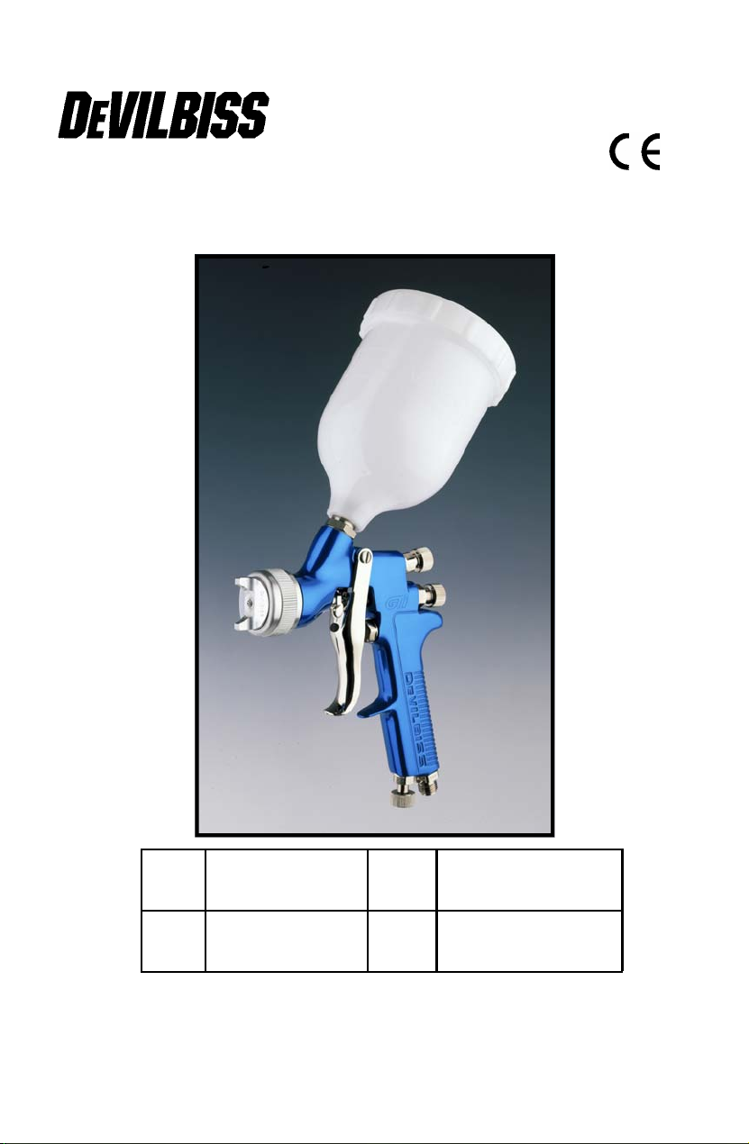
Operation Manual
GTi – Gravity Spraygun
E
E
DK
DK
P 2 - 7
P 8 - 13
SV
SV
FIFI
1 © ITW Ltd 2000
P 14 –19
P 20 - 25
Page 2
EE
Operation Manual
GTi – Gravity Spraygun
Important
Read and follow all instructions and Safety Precautions before using this
equipment
Description
This product is suitable for use with both waterbased and solvent based
coating materials. The design uses EPA compliant atomising technology to
reduce overspray and improve coating efficiency.
Important: These guns are not designed for use with highly corrosive and/
or abrasive materials and if used with such materials it must be expected
that the need for cleaning and/or replacement of parts will be increased. If
there is any doubt regarding the suitability of a specific material contact
your local Distributor or ITW Finishing direct.
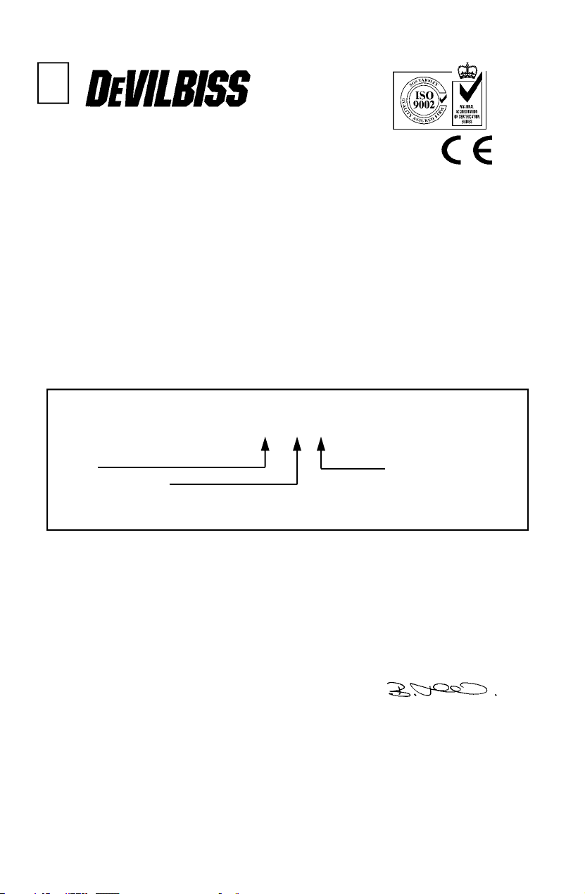
Model Part Number
Example: GTI-G110B-14
Aircap Fluid nozzle size
(14 = 1,4 mm)
Gunbody Finish
M= Multi Colour (colours may vary), B= Blue Anodised
Declaration of Conformity
We, ITW Finishing UK, Ringwood Road Bournemouth Dorset England
declare under our sole responsibility that this product is in conformity with BS
EN 292: parts 1 and 2 :1991 and BS EN 1953:1999, following the provisions
of the Machinery Directive 89/392/EEC. This product also complies with the
requirements of the EPA guidelines, PG6/34. Transfer efficiency certificates
are available on request.
B. Holt, General Manager
2 © ITW Ltd 2000
Page 3
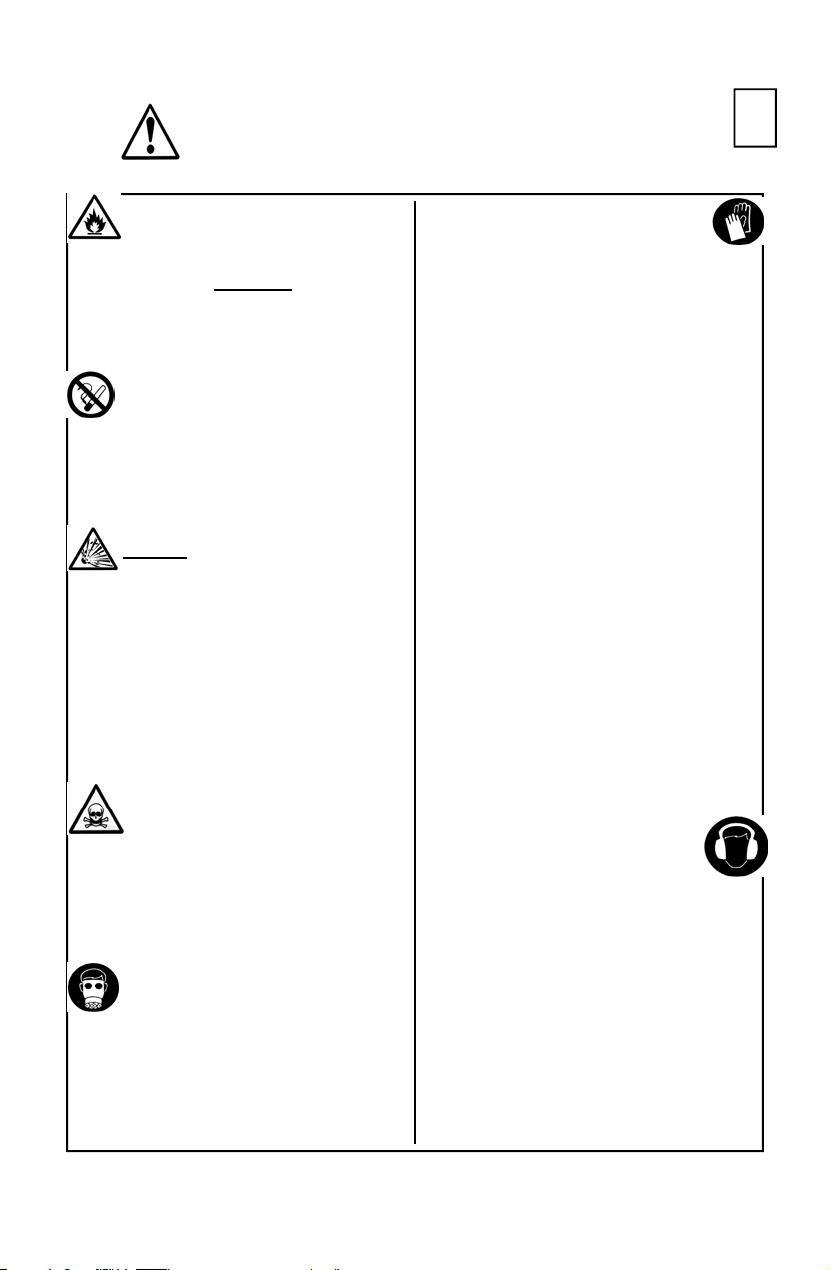
SAFETY WARNINGS
EE
Fire and explosion
Solvents and coating materials
can be highly flammable or combustible
when sprayed. ALWAYS
coating material suppliers
instructions and COSHH sheets
before using this equipment
Users must comply with all local
and national codes of practice and
insurance company requirements
governing ventilation, fire precautions,
operation and house-keeping of working
areas
This equipment, as supplied, is
NOT
Halogenated Hydrocarbons.
Static Electricity can be generated by
fluid and/or air passing though hoses. To
prevent such a risk, earth continuity to
the spray equipment and the object
being sprayed should be maintained.
suitable for use with
refer to the
Personal Protective
Equipment
Toxic vapours – When sprayed,
certain materials may be
poisonous, create irritation or be
otherwise harmful to health.
Always read all labels and safety data
sheets for the material before spraying
and follow any recommendations. If In
Doubt, Contact Your Material Supplier
The use of respiratory protective
equipment is recommended at all
times. The type of equipment must
be compatible with the material
being sprayed
Gloves must be worn when
spraying or cleaning the
equipment
Training – Personnel should be given
adequate training in the safe use of
spraying equipment.
Misuse
Never aim a spraygun at any part of the
body
Never exceed the max. recommended
safe working pressure for the equipment
The fitting of non-recommended or nonoriginal spares may create hazards
Before cleaning or maintenance, all
pressure must be isolated and relieved
from the equipment
The product should be cleaned using a
gun washing machine. However, this
equipment should not be left inside gun
washing machines for prolonged periods
of time.
Noise Levels
The A-weighted sound level of
sprayguns may exceed 85 dB (A)
depending on the set-up being
used. Details of actual noise
levels are available on request. It is
recommended that ear protection is worn
at all times when spraying
Always wear eye protection when
spraying or cleaning the spraygun
3 © ITW Ltd 2000
Page 4

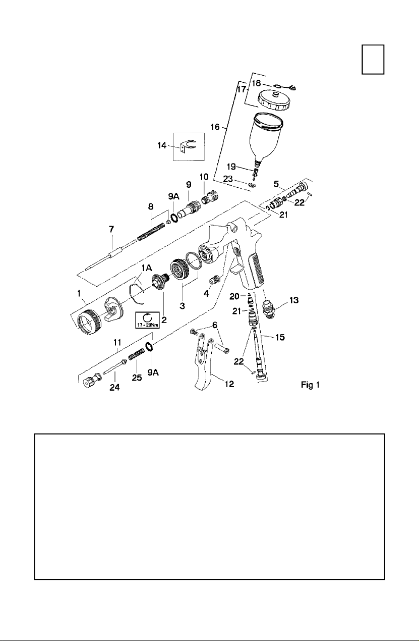
Parts List
Ref. No Description Part Number Qty
*1 Air Cap/Retaining ring GTI-407-* 1
1a Spring Clip JGA-156-K5 1
+**2
3
+4 Packing GTI-439-K2 1
5 Spreader Valve GTI-404-K 1
6 Stud and Screw GTI-408-K5 1
+7
+8 Spring and Pad GTI-409-K5 1
9 Bushing GTI-402-K 1
9a Seal kit of 5 JGS-72-K5 2
10 Needle Adjusting Screw GTI-414-K 1
11 Valve Assembly JGK-449 1
12 Trigger GTI-108 1
13 Connector JGA-158 1
14 Gun Hook GFG-6 1
15 Airflow Valve GTI-415-K 1
16 1/2 Ltr Gravity Cup Kit GFC-501 1
17 Cup Lid GFC-402 1
18 Drip Check Lid kit of 5 GFC-2-K5 1
19 Filter KGP-5 1
20 Circlip 25746-007-K5 1
21 Circlip SST-8434-K5 2
22 Seal & Pin Kit ( + SST-8434-K5) GTI-428-K5 2
23 Washer GFC-17-K5 1
24 Air valve stem assembly JGS-431-1 1
25 Spring JGV-262-K5 1
Nozzle (up to 1.5 mm) GTI-213-**-K 1
Nozzle (1.6 mm to 2.2 mm) GTI-214-**-K 1
Baffle & Seal GTI-425-K 1
Baffle Seal - Kit of 5 GTI-33-K5 1
Needle (for GTI-214 Tip) GTI-420-K 1
Needle (for GTI-213 Tip) GTI-413-K 1
* - * Denotes Aircap Number - Available Aircaps No’s 105 and 110
** - ** Denotes Fluid Tip Size—Available Sizes;
GTI-213 0.85, 1.0, 1.1, 1.2, 1.3,1.4,1.5 mm
GTI-214 1.6, 1.8, 2.0 and 2.2 mm
+ - Parts included in service Kit (see accessories)
4 © ITW Ltd 2000
Page 5
EE
Specification
Air supply connection - Universal
Maximum static inlet pressure - P
Nominal gun inlet pressure with gun triggered - 2 bar (29 psi)
Gun Weight - 580 g
= 9 bar (130 psi)
1
Materials of Construction
Gun body - Anodised Aluminium
Nozzle - Stainless steel
Needle - Stainless Steel
Cup - Acetal and Stainless Steel
5 © ITW Ltd 2000
1
/4 BSP and NPS
Page 6
EE
Installation
Important: To ensure that this
equipment reaches you in first class
condition, protective coatings have
been use. Flush the equipment
through with a suitable solvent
before use.
Operation
1. Mix coating material to
manufacturers instructions
2. Turn needle adjusting screw (10)
counter-clockwise until first thread
shows
3. Turn pattern valve (5) counterclockwise to fully open
4. Adjust inlet air pressure to give 2
bar (29psi) at the gun inlet with
the gun triggered. (pressure
gauge attachment shown under
Accessories is recommended for
this)
5. Test spray. If the finish is too dry
reduce airflow by reducing inlet
pressure. If finish is too wet
reduce fluid flow by turning needle
screw (10) clockwise. If
atomisation is too coarse,
increase inlet air pressure. If too
1. Attach air hose to connector (13).
Recommended hose size 8 mm
bore.
2. Air supply should be filtered and
regulated.
fine reduce inlet pressure.
6. The pattern size can be reduced
by adjusting valve (5)
7. Hold gun perpendicular to surface
being sprayed. Arcing or tilting
may result in uneven coating.
8. The recommended spray distance
is 150-200 mm (6”-8”).
9. Spray edges first. Overlap each
stroke a minimum of 50%. Move
gun at a constant speed.
10. Always turn off air supply and
relieve pressure when gun is not
in use.
Air Flow Valve (15)
1. If the airflow valve (15) is fitted
this can be used to reduce the
inlet pressure through the gun.
Screw the Adjusting Knob in to
reduce pressure.
Preventative Maintenance
1. Turn off air supply and relieve
pressure in the airline, or if using
QD system, disconnect from
airline.
2. Empty coating material into a
suitable container and clean,
preferably in a gun wash
machine.
3. Remove air cap and clean. If any
of the holes in the cap are
blocked with coating material use
a toothpick to clean. Never use
metal wire which could damage
the cap and produce distorted
spray patterns
4. Ensure the tip of the nozzle is
clean and free from damage.
Build up of dried paint can distort
the spray pattern.
5. Lubrication – stud/screw (6),
needle (7) and air valve (11)
should be oiled each day.
6 © ITW Ltd 2000
Page 7
Replacement of Parts
EE
Nozzle (2) and Needle (7) –
Remove parts in the following order:
10, 8, 7, 1 and 2. Replace any worn
or damaged parts and re-assemble
in reverse order. Recommended
tightening torque for nozzle (2) 1720 Nm (150-180 lbf in)
Packing – Remove parts 10, 8, 7.
Unscrew cartridge (4). Fit new
cartridge finger tight. Re-assemble
parts 7, 8, and 10 and tighten
cartridge (4) with spanner sufficient
to seal but to allow free movement
of needle. Lubricate with gun oil.
Air valve – Remove parts 6 and 12.
Unscrew valve assembly. Reassemble fitting spring to valve head
Spreader valve – Caution: always
ensure that the valve is in the fully
open position by turning screw fully
counter-clockwise before fitting to
body.
Air cap / Nozzle Selection
Refer to coating material
manufacturers recommendations or
ITW Finishing UK Website:
www.itweuropeanfinishing.com
Accessories
Spanner – order SPN-5
Cleaning Brush – order 4900-5-1-K3
Service Kit – order GTi-416 add nozzle size as required (i.e. GTi-416-14)
Pressure gauge Attachment – order GA-515
Gun Mounted Regulator – order DVR-501
Lubricant - order GL-1-K10
7 © ITW Ltd 2000
Page 8
DKDK
Betjeningsvejledning
GTi – Sprøjtepistol med tyngdefødning
Vigtigt
Læs og følg vejledningen og alle sikkerhedsforholdsreglerne nøje, før du
bruger dette udstyr.
Dette produkt kan bruges både i forbindelse med vandbaseret og opløsningsmiddelbaseret sprøjtemateriale. Sprøjtepistolen bruger en forstøvningsteknik, der er i
overensstemmelse med EPAs retningslinier og mindsker overspray og gør
sprøjtebehandlingen mere effektiv.
Vigtigt: Disse pistoler kan ikke tåle at blive brugt i forbindelse med meget korrosive
og/eller slibende materialer. Hvis de bruges i forbindelse med sådanne materialer,
må det forventes, at de skal renses mere og/eller at antallet af dele, der skal
udskiftes, stiger. Hvis du er i tvivl om, hvorvidt et produkt er egnet, kan du kontakte
din lokale forhandler, eller du kan kontakte ITW Finishing direkte.
Reservedels modelnummer
Eksempel: GTI-G110B-14
Lufthætte Væskedysestørrelse
(14 = 1,4 mm)
Pistolfinish
M= Flerfarvet (farverne kan variere), B= Anodiseret blå
Overensstemmelseserklæring
Vi, ITW Finishing UK, Ringwood Road, Bournemouth, Dorset, England erklærer at
have det fulde ansvar for, at dette produkt er i overensstemmelse med BS EN 292:
del 1 og 2 :1991 og BS EN 1953:1999, og følger de gældende retningslinier i henhold
til maskindirektivet 89/392/EØF. Dette produkt overholder også kravene i henhold til
EPA-retningslinierne, PG6/34. Ved henvendelse kan man få et effektivitetscertifikat
vedrørende overførsel.
B. Holt, Administrerende direktør
8 © ITW Ltd 2000
8
Page 9

Reservedelsliste
Ref. Nr. Beskrivelse Reservedelsnummer Antal
*1 Lufthætte/omløberring GTI-407-* 1
1a Fjederholder JGA-156-K5 1
+**2
3 Luftfordelerring og taetning GTI-425-K 1
Taetning til Luftfordelerring saet med 5 GTI-33-K5 1
+4 Pakning GTI-439-K2 1
5 Sprederjustering GTI-404-K 1
6 Pindbolt og skrue GTI-408-K5 1
+7 Nål (til GTI-214-dyse) GTI-420-K 1
Nål (til GTI-213-dyse) GTI-413-K 1
+8 Fjeder og pude GTI-409-K5 1
9 Bøsning GTI-402-K 1
9a Tætnings– sæt med 5 JGS-72-K5 2
10 Nåljusterskrue GTI-414-K 1
11 Luftventil JGK-449 1
12 Aftrækker GTI-108 1
13 Luftindgangsnippel JGA-158 1
14 Pistolkrog GFG-6 1
15 Luftreguleringsventil GTI-415-K 1
16 1/2 l overkop GFC-501 1
17 Låg GFC-402 1
18 5 sæt dryplåg GFC-2-K5 1
19 Filter KGP-5 1
20 Låsering – sæt med 5 25746-007-K5 1
21 Låsering – sæt med 5 SST-8434-K5 2
22 Tætnings- og stiftsæt ( + SST-8434- GTI-428-K5 2
23 Skive GFC-17-K5 1
24 Ventil JGS-431-1 1
25 Fjeder JGV-262-K5 1
Dyse (op til 1,5 mm) GTI-213-**-K 1
Dyse (1,6 mm til 2,2 mm) GTI-214-**-K 1
DK
DK
* - ** Betegner Lufthættenummer – Fås i lufthættenumrene 105 og 110
** - ** Betegner væskespidsens størrelse – Fås i følgende størrelser;
GTI-213 0,85; 1,0; 1,1; 1,2; 1,3; 1,4; 1,5 mm
GTI-214 1,6; 1,8; 2,0 og 2,2 mm
+ - Reservedele i servicesæt (se tilbehør)
© ITW Ltd 2000
9 © ITW Ltd 2000
Page 10

DK
DK
Specifikation
Luftforsyningsforbindelse - Universal
Maksimalt statisk indgangstryk - P
Nominelt indgangstryk når pistolen er i brug - 2 bar (29 psi)
Pistolens vægt - 580 g
= 9 bar (130 psi)
1
Konstruktionsmateriale
Pistol - Anodiseret aluminium
Dyse - Rustfrit stål
Nål - Rustfrit stål
Kop - Acetal og rustfrit stål
10 © ITW Ltd 2000
1
/4 BSP og NPS
Page 11

Installation
Vigtigt: For at sikre at dette udstyr når
frem i bedste stand, har vi overfladebeskyttet materialet. Skyl udstyret
igennem med et egnet opløsningsmiddel før brug.
Betjening
1. Bland sprøjtematerialet efter
producentens vejledning.
2. Drej nåljusterskruen (10) mod uret,
indtil det første gevind bliver synlig.
3. Drej viftereguleringen (5) mod uret for
at åbne den fuldstændig.
4. Juster luftindgangstrykket til 2 bar
(29psi) ved pistolåbningen, mens du
holder aftrækkeren inde. (Det
anbefales at bruge et trykmanometer
til dette, som vist under Tilbehør).
5. Testspray. Hvis finishen er for tør,
kan man reducere luftstrømmen ved
at reducere indgangstrykket. Hvis
finishen er for våd, kan man reducere
væskestrømmen ved at dreje
nålskruen (10) med uret. Hvis
forstøvningen er for grov, kan man
øge luftindgangstrykket. Hvis
forstøvningen er for fin, skal man
reducere indgangstrykket.
6. Mønsterstørrelsen kan reduceres ved
at justere ventilen (5).
DK
DK
1. Tilslut luftslangen til
forbindelsesdelen (13). Den
anbefalede slangestørrelse har en
åbning på 8 mm.
2. Luftforsyningen skal filtreres og
reguleres.
7. Hold pistolen vinkelret på den
overflade, der sprøjtes. Hvis man
buer eller hælder den, kan det
medføre en ujævn
overfladebehandling.
8. Den tilrådelige sprøjteafstand er 150-
200 mm.
9. Spray kanterne først. Overlap hvert
strøg med minimum 50%. Bevæg
pistolen med konstant hastighed.
10. Sluk altid for luftforsyningen og
væskeforsyningen udløs trykket, når
pistolen ikke er i brug.
Luftventil (15)
1. Hvis luftventilen (15) er indstillet, kan
det hjælpe med at reducere
indgangstrykket gennem pistolen.
Skru justeringsgrebet ind for at
reducere trykket.
Forebyggende vedligeholdelse
1. Sluk for luftforsyningen og udløs
trykket i luftledningen, eller frakobl
luftledningen, hvis der anvendes et
QD-system.
2. H æ l d
overfladebehandlingsmaterialet i en
egnet beholder, og rens udstyret,
helst i en pistolrensemaskine.
3. Fjern lufthætten og rens den. Hvis
nogle af hullerne i hætten er
tilstoppet, kan man bruge en tandstik
11 © ITW Ltd 2000
til at rense dem med. Brug aldrig
ståltråd, da det kan ødelægge
hætten og forårsage et forvrænget
sprøjtemønster.
4. Kontrollér, at dysens spids er ren og
ubeskadiget. Lag på lag af tørret
maling kan forårsage et forvrænget
sprøjtemønster.
5. Smøring – pindbolt/skrue (6), nål (7)
og luftventil (11) bør smøres med
olie hver dag.
Page 12

DK
DK
Udskiftning af dele
Dyse (2) og nål (7) – Fjern delene i
følgende rækkefølge: 10, 8, 7, 1 og 2.
Udskift de slidte eller beskadigede dele,
og saml dem i omvendt rækkefølge. Det
anbefales at bruge følgende
tilspændingsmoment til dyse (2): 17-20
Nm.
Pakning – Fjern delene 10, 8, 7. Skru
indsatsen løs (4). Skru den nye indsats i
med fingerkraft. Saml delene 7, 8, og 10,
og stram indsatsen (4) med en
skruenøgle, så den er tæt, men så nålen
stadig kan bevæge sig frit. Smør med
pistololie.
Luftventil – Fjern delene 6 og 12. Skru
ventilsættet løs. Saml delene ved at
sætte fjederen sammen med
ventilhovedet.
Sprederjustering – Forsigtig: Sørg
altid for, at ventilen er i den fuldt åbne
position, ved at dreje skruen helt mod
uret, før du sætter den på.
Valg af lufthætte/dyse
Vi henviser til de anbefalinger, som
producenten af sprøjtematerialet har
givet eller til ITW Finishing UK's
Webside:
www.itweuropeanfinishing.com
Tilbehør
Skruenøgle – bestil SPN-5
Rengøringsbørste – bestil 4900-5-1-K3
Servicesæt – bestil GTi-416 tilføj den rigtige dysestørrelse (d.v.s. GTi-416-14)
Trykmanometer – bestil GA-515
Pistolmonteret regulator – bestil DVR-501
Smøremiddel – bestil GL-1-K10
12 © ITW Ltd 2000
Page 13

SIKKERHEDSADVARSLER
DK
DK
Brand og eksplosion
Opløsningsmidler og sprøjtematerialer kan være meget
brandfarlige og letantændelig, når man
sprøjter med dem. Læs altid
sprøjtematerialeleverandørens
vejledning og dokumenter med
bestemmelser om helbredsskadelige
stoffer inden brug af dette udstyr.
Brugerne skal overholde alle lokale
og nationale brugerregler samt
forsikringsselskabers krav til
ventilation, brandforanstaltninger,
betjening og rengøring af
arbejdsområder.
Dette udstyr er, som leveret, IKKE
egnet til brug i forbindelse med
halogenerede carbonhydrider.
Væske og/eller luft, der passerer
gennem slanger, kan generere statisk
elektricitet. For at forhindre en sådan
risiko bør sprøjteudstyret og genstanden,
der sprøjtes, hele tiden have
jordforbindelse.
Anvend altid beskyttelsesbriller, når du
sprøjter eller renser sprøjtemaskinen.
Brug altid handsker, når du
sprøjter eller renser udstyret.
Uddannelse – Personalet bør uddannes
tilstrækkeligt i, hvordan man bruger
sprøjteudstyret på den sikreste måde.
Forkert brug
Ret aldrig sprøjtepistolen mod en
legemsdel.
Lad aldrig udstyret overstige det højst
anbefalede sikre arbejdstryk.
Det kan være fagligt at anvende ikkeanbefalet eller uoriginale reservedele.
Før rensning eller vedligeholdelse skal al
udstyrets tryk være isoleret og udløst.
Produktet bør renses i en pistolrensemaskine. Udstyret må dog ikke
ligge i pistolrensemaskinen i længere tid
af gangen.
Personligt beskyttelsesudstyr
Giftige dampe – Visse materialer
kan være giftige, forårsage
irritation eller på anden måde
være skadelige for helbredet, når
man sprøjter med dem. Læs altid
etiketterne og materialets sikkerhedsinformationer, før sprøjtning
påbegyndes, og følg anbefalingerne.
Kontakt din materialeleverandør, hvis
du er i tvivl.
Det anbefales til enhver tid at
bruge udstyr, der forhindrer
indånding af giftige dampe.
Udstyrets type skal svare til det
materiale, der sprøjtes med.
Sprøjtepistolers A-vægtede
støjniveau kan overstige 85 dB
(A) afhængig af hvilke
arbejdsformer, der anvendes.
Ved henvendelse kan man
få detaljer for relevante støjniveauer. Det
anbefales, at man altid benytter en form
for ørebeskyttelse, når man sprøjter.
13 © ITW Ltd 2000
Støjniveau
Page 14

SVSV
Bruksanvisning
GTi – Sprutpistol med självtryck
Viktigt
Läs igenom och följ alla instruktioner och säkerhetsföreskrifter innan du använder
Den här produkten lämpar sig för användning med både vattenbaserade och
oljebaserade material. För att minska översprutning och öka
bestrykningseffektiviteten används en EPA-godkänd fördelningsteknik.
Viktigt! De här pistolerna är inte avsedda för användning med starkt frätande och/
eller nötande material. Om dessa ändå används är det viktigt att tänka på att
behovet av rengöring och/eller byte av delar då ökar. Om du är tveksam huruvida ett
visst material lämpar sig för utrustningen kan du endera kontakta din lokala
distributör eller ITW Finishing direkt.
Modell, delnummer
Exempel: GTI-G110 B- 14
Luftmunstycke Dysa, innerdimension
(14 = 1,4 mm)
Pistolhus, ytfinish
M= Flerfärg (färg kan variera), B= Blå, eloxerad
utrustningen.
Beskrivning
Överensstämmelseförklaring
Härmed förklarar vi, ITW Finishing UK, Ringwood Road, Bournemouth,
Dorset, England, som ensam ansvarig, att den här produkten
överensstämmer med standarderna BS EN 292: delar 1 och 2 :1991 samt BS
EN 1953:1999, i enlighet med bestämmelserna i maskindirektivet 89/392/
EEG. Produkten överensstämmer också med kraven i EPA:s riktlinjer,
PG6/34. Certifikat rörande överföringseffektivitet finns att få på begäran.
B. Holt, General Manager
14 © ITW Ltd 2000
Page 15

Dellista
Ref. nr Beskrivning Delnr Antal
*1 Luftmunstycke/stoppring GTI-407-* 1
1a Fjäderklämma JGA-156-K5 1
+**2
3 Fördelarplatta & tatning GTI-425-K 1
+4 Packning GTI-439-K2 1
5 Fördelarventil GTI-404-K 1
6 Bult och skruv GTI-408-K5 1
+7 Nål (till GTI-214 färgmunstycke) GTI-420-K 1
+8 Fjäder och dyna GTI-409-K5 1
9 Bussning GTI-402-K 1
9a Tætnings– sats om 5 JGS-72-K5 2
10 Justerskruv till nål GTI-414-K 1
11 Ventilsats JGK-449 1
12 Avtryckare GTI-108 1
13 Anslutning JGA-158 1
14 Pistolkrok GFG-6 1
15 Luftströmningsventil GTI-415-K 1
16 1/2 l koppsats för självtrycksmatning GFC-501 1
17 Kopplock GFC-402 1
18 Droppfångarlock, sats om 5 GFC-2-K5 1
19 Filter KGP-5 1
20 Fjäderbricka – Sats om 5 25746-007-K5 1
21 Fjäderbricka – Sats om 5 SST-8434-K5 2
22 Tätnings- och stiftsats ( + SST-8434-K5) GTI-428-K5 2
23 Packning GFC-17-K5 1
24 Ventil JGS-431-1 1
25 Fjäder JGV-262-K5 1
Dysa (upp till 1,5 mm) GTI-213-**-K 1
Dysa (1,6 mm till 2,2 mm) GTI-214-**-K 1
Fördelarplattatatning GTI-33-K5
Nål (till GTI-213 färgmunstycke) GTI-413-K
SVSV
* - ** Avser luftmunstyckesnummer – tillgängliga luftmunstycken nr 105
och 110
** - ** Avser innerdimension – tillgängliga storlekar:
GTI-213 0,85, 1,0, 1,1, 1,2, 1,3, 1,4 och 1,5 mm
GTI-214 1,6, 1,8, 2,0 och 2,2 mm
+ - Ingående delar i servicesatsen (se tillbehör)
15 © ITW Ltd 2000
Page 16

SVSV
Specifikation
Anslutning till luftintag - Universal
Maximalt statiskt inströmningstryck - P
Nominellt inströmningstryck med avtryckaren
aktiverad - 2 bar
Pistolens vikt - 580 g
= 9 bar
1
Pistolhus - Eloxerad aluminium
Dysa - Rostfritt stål
Nål - Rostfritt stål
Kopp - Acetal och rostfritt stål
Konstruktionsmaterial
16 © ITW Ltd 2000
1
/4 BSP och NPS
Page 17

Installation
SVSV
Viktigt! För att försäkra oss om att
utrustningen når dig i toppskick har
ett skyddsöverdrag använts. Spola
igenom utrustningen med lämpligt
lösningsmedel innan du använder den.
Användning
1. Blanda bestrykningsmaterialet enligt
tillverkarens instruktioner.
2. Vrid nålens justerskruv (10) motsols
tills du kan se den första gängan.
3. Vrid mönsterventilen (5) motsols för
att öppna helt.
4. Justera inströmningstrycket till att ge
2 bar vid pistolens intag med
avtryckaren aktiverad. (För detta
rekommenderas
tryckmätaraggregatet under
Tillbehör.)
5. Provspruta. Om ytan är för torr ska du
minska luftflödet genom att minska
inströmningstrycket. Om ytan är för
blöt ska du minska färgflödet genom
att vrida nålens justerskruv (10)
medsols. Om fördelningen är för grov
ska du öka inströmningstrycket. Om
den är för fin ska du minska
1. Anslut luftslangen till anslutningen
(13). Slang med en diameter om 8
mm rekommenderas.
2. Luftintaget bör filtreras och regleras.
inströmmningstrycket.
6. Mönsterstorleken kan minskas genom
att du justerar ventilen (5).
7. Håll pistolen i rät vinkel mot den yta
som sprutas. Vinkling eller lutning kan
leda till att bestrykningen blir ojämn.
8. Rekommenderat sprutavstånd är 150-
200 mm.
9. Spruta kanterna först. Spruta över
minst 50 % av varje färgdrag. Flytta
pistolen med konstant hastighet.
10. Slå alltid ifrån luftintaget och lätta på
trycket när du inte använder pistolen.
Luftströmningsventil (15)
1. Om pistolen har en luft-
strömningsventil (15) kan denna
användas till att minska
inströmningstrycket genom pistolen.
Skruva justerratten inåt för att minska
Förebyggande underhåll
1. Slå ifrån luftintaget och lätta på
trycket i luftledningen. Om du
använder snabbkopplingssystemet,
koppla bort luftledningen.
2. Töm materialet i en lämplig behållare
och rengör pistolen, helst i en
pistolrengöringsmaskin.
3. Ta bort och rengör luftmunstycket.
Om något av hålen i locket är
blockerat med färg ska du rengöra
det med en tandpetare. Använd
aldrig metalltråd som kan skada
locket och leda till förvanskade
sprutmönster.
4. Kontrollera att dysans spets är ren
och att den inte är skadad.
Ansamling av torkad färg kan
förvanska sprutmönstret.
5. Smörjning – bult/skruv (6), nål (7)
och luftventil (11) bör smörjas varje
dag.
17 © ITW Ltd 2000
Page 18

SVSV
Byte av delar
Dysa (2) och nål (7) – Ta bort delarna i
följande ordningsföljd: 10, 8, 7, 1 och 2.
Byt ut alla slitna eller skadade delar och
sätt tillbaka i omvänd ordning.
Rekommenderat åtdragningsmoment för
dysan (2) är 17-20 Nm.
Packning – Ta bort delarna 10, 8, 7.
Skruva loss patronen (4). Sätt dit den
nya patronen och dra åt för hand. Sätt
tillbaka delarna 7, 8 och 10 och dra åt
patronen (4) med skruvnyckel så pass
att det blir tätt. Se dock till att nålen kan
röra sig fritt. Smörj med vapenolja.
Luftventil – Ta bort delarna 6 och 12.
Skruva isär ventilsatsen. Montera ihop
genom att passa in fjädern på
ventilhuvudet.
Fördelarventil – Varning: kontrollera
att ventilen är helt öppen genom att
vrida skruven motsols så långt det går,
innan den monteras på huset.
Val av luftmunstycke / dysa
Se rekommendationer från materialtillverkare eller ITW Finishing UK:s
webbsida:
www.itweuropeanfinishing.com
Tillbehör
Skiftnyckel – beställningsnr SPN-5
Rengöringsborste – beställningsnr 4900-5-1-K3
Servicesats – beställningsnr GTi-416, specificera dysans storlek (t.ex. GTi-416-14)
Tryckmätaraggregat – beställningsnr GA-515
Pistolmonterat reglage – beställningsnr DVR-501
Smörjmedel – beställningsnr GL-1-K10
18 © ITW Ltd 2000
Page 19

SÄKERHETSVARNINGAR
SVSV
Brand och explosion
Lösningsmedel och bestrykningsmaterial kan vara mycket
brandfarliga och lättantändliga när de
sprutas. Läs ALLTID
materialleverantörens anvisningar
och COSHH-bladen innan du
använder utrustningen.
Användare måste följa alla lokala
och nationella föreskrifter samt
försäkringsbolagens krav rörande
ventilation, brandskydd, drift och skötsel
av arbetsområdet.
Utrustningen är i leveransskicket
lämpat för användning med
INTE
halogenkolväten.
Statisk elektricitet kan genereras av
vätskor och/eller luft som passerar
genom slangarna. För att motverka
denna risk ska sprututrustningens
förlängning jordas och det föremål som
sprutas ska underhållas.
Personlig
skyddsutrustning
Giftiga ångor – Vissa material kan
vid sprutning vara giftiga, orsaka
irritation eller på annat sätt vara skadliga
för hälsan. Läs alltid
alla etiketter och säkerhetsblad för
materialet innan sprutning. Följ alla
rekommendationer. Om du är
tveksam ska du kontakta
materialleverantören.
Du rekommenderas att alltid bära
andningsskydd. Utrustningen måste vara
kompatibel med det material som
sprutas.
Bär alltid ögonskydd vid sprutning
eller rengöring av sprutpistolen.
Handskar skall bäras vid sprutning eller
rengöring av utrustningen.
Utbildning – Personal bör ges lämplig
utbildning med avseende på säker
användning av sprututrustningen.
Missbruk
Rikta aldrig en sprutpistol mot någon del
av kroppen.
Överstig aldrig utrustningens maximala
rekommenderade säkra arbetstryck.
Montering av icke-rekommenderade
delar eller icke-originaldelar på
utrustningen kan utgöra fara.
Innan rengöring eller underhåll måste allt
tryck isoleras och släppas ut från
utrustningen.
Produkten bör rengöras med hjälp av en
pistolrengöringsmaskin. Utrustningen bör
emellertid inte lämnas inuti rengöringsmaskinen någon längre tid.
Bullernivå
Sprutpistolernas A-vägda
bullernivå kan överstiga 85 dB (A)
beroende på vilken installation som
används. Information om faktiska
bullernivåer kan fås på begäran. Vi
rekommenderar att hörselskydd alltid
bärs vid sprutning.
19 © ITW Ltd 2000
Page 20

FIFI
Käyttöohje
GTi – yläsäiliömaaliruisku
Tärkeää
Perehdy kaikkiin ohjeisiin ja varotoimiin ennen laitteen käyttöä ja noudata
niitä
Kuvaus
Tämä tuote sopii käytettäväksi sekä vesi- että liuotinpohjaisten pinnoitusaineiden
kanssa. Mallissa käytetään ympäristömääräysten mukaista sumutustekniikkaa, joka
vähentää liikasumutusta ja parantaa pinnoitustehoa.
Tärkeää: Näitä ruiskuja ei ole tarkoitettu käytettäväksi erityisen syövyttävien ja/tai
hankaavien aineiden kanssa. Jos niitä käytetään tällaisten aineiden kanssa,
puhdistuksen tarve todennäköisesti lisääntyy ja/tai osia on vaihdettava useammin.
Mikäli et ole varma jonkin aineen sopivuudesta laitteelle, ota yhteyttä paikalliseen
jälleenmyyjään tai suoraan ITW Finishingiin
Mallin osanumero
Esimerkki: GTI-G110B-14
Ilmasuutin Nestesuuttimen koko
(14 = 1,4 mm)
Ruiskun rungon pintakäsittely
M= useita eri värejä, B = sininen eloksoitu
EU:n vaatimuksenmukaisuusvakuutus
ITW Finishing UK, Ringwood Road, Bournemouth, Dorset, England vakuuttaa, että
tämä tuote on standardin EN 292, osien 1 ja 2 :1991 sekä standardin EN 1953:1999
mukainen ja täyttää konedirektiivin 89/392/ETY vaatimukset. Tuote on myös EPA:n
ohjeen PG6/34 mukainen. Todistukset siirron hyötysuhteesta toimitetaan
pyydettäessä.
B. Holt,
Johtaja
20 © ITW Ltd 2000
Page 21

Osaluettelo
Viite-numero Kuvaus Osanumero Kpl
*1 Ilmasuutin/kiinnitysrengas GTI-407-* 1
1a Jousikiinnike JGA-156-K5 1
+**2
3 Ilmanjakorengas ja tiiviste GTI-425-K 1
+4 Tiivistesarja GTI-439-K2 1
5 Viuhkansäätö (viuhka) GTI-404-K 1
6 Liipaisinpultti ja ruuvi GTI-408-K5 1
+7
+8 Jousi ja tyyny GTI-409-K5 1
9 Holkki GTI-402-K 1
10 Neulan säätöruuvi GTI-414-K 1
11 Ilmaventtiili JGK-449 1
12 Liipaisin GTI-108 1
13 Liitin JGA-158 1
14 Ruiskun pidike GFG-6 1
15 Ilmanvirtausventtiili GTI-415-K 1
16 1/2 l yläsäiliösarja GFC-501 1
17 Säiliön kansi GFC-402 1
18 Tipanestin, 5 GFC-2-K5 1
19 Suodatin KGP-5 1
20 Lukitusrengas 25746-007-K5 1
21 Lukitusrengas SST-8434-K52 1
22 Ilmaventtiilin tiivistesarja ( + SST-8434-K5) GTI-428-K5 1
23 Tiivisterengas GFC-17-K5 1
24 Venttiili JGS-431-1 1
25 Jousi JGV-262-K5 1
Suutin (1,5 mm:iin saakka) GTI-213-**-K 1
Suutin (1,6 mm – 2,2 mm) GTI-214-**-K 1
Ilmanjakorenkaan tiiviste - 5 sarja GTI-33-K5 1
Neula (GTI-214 nestesuuttimelle) GTI-420-K 1
Neula (GTI-213 nestesuuttimelle) GTI-413-K 1
FIFI
* - ** Ilmaisee ilmakannen numeron – saatavissa numerot 105 ja 110
** - ** Ilmaisee värisuuttimen koon – saatavissa seuraavat koot:
GTI-213 0,85 mm; 1,0 mm; 1,1 mm; 1,2 mm; 1,3 mm; 1,4 mm
ja 1,5 mm
GTI-214 1,6 mm; 1,8 mm; 2,0 mm ja 2,2 mm
+ - huoltosarjaan sisältyvät osat (katso lisävarusteet)
21 © ITW Ltd 2000
Page 22

Tekniset tiedot
Ilmaletkun liitäntä - Yleiskierre
Suurin staattinen tulopaine - P
= 9 bar (130 psi)
1
Nimellispaine laukaistaessa - 2 bar (29 psi)
Ruiskun paino - 580 g
Valmistusmateriaali
Ruiskun runko - eloksoitu alumiini
Suutin - ruostumaton teräs
Neula - ruostumaton teräs
Kansi - asetaali ja ruostumaton teräs
22 © ITW Ltd 2000
1
/4 " BSP ja NPS
Page 23

Asennus
FIFI
Tärkeää: Varmistaaksemme sen, että
saat laitteen ensiluokkaisessa kunnossa,
olemme käsitelleet laitteen pinnan suojaaineella. Huuhtele laite ennen käyttöä
sopivalla liuottimella.
Käyttö
1. Sekoita pinnoitusaine valmistajan
ohjeiden mukaisesti.
2. Kierrä neulansäätöruuvia (10)
vastapäivään, kunnes ensimmäinen
kierre näkyy.
3. Kierrä kuvioventtiiliä (5) vastapäivään,
kunnes se on kokonaan auki.
4. Säädä tuloilman paine siten, että se
on 2 baria (29 psi) ruiskun tuloaukolla
laukaistaessa. (Tähän tarkoitukseen
suositellaan Lisätarvikkeet-kohdassa
mainittua painemittarin liitintä.)
5. Testaa ruiskutusjälki. Jos jälki on liian
kuiva, vähennä ilmanvirtausta
alentamalla tulopainetta. Jos jälki on
liian märkä, vähennä nesteenvirtausta
kiertämällä neulan säätöruuvia (10)
myötäpäivään. Jos sumu on liian
paksua, lisää tuloilman painetta. Jos
sumu on liian hienoa, alenna
ilmanpainetta.
1. Liitä ilmaletku liittimeen (13).
Suositeltava letkun sisähalkaisija on
8 mm.
2. Ilman pitää olla suodatettua ja
säädeltyä.
6. Kuvion kokoa voidaan pienentää
säätämällä venttiiliä (5).
7. Pidä ruiskua kohtisuorassa
ruiskutettavaan pintaan nähden.
Kaarevat liikkeet tai ruiskun
kallistaminen saattavat aiheuttaa
epätasaisen jäljen.
8. Suositeltava ruiskutusetäisyys on 150
- 200 mm.
9. Ruiskuta ensin reunat. Peitä jokaisella
vedolla vähintään puolet edellisellä
vedolla maalatusta alueesta. Liikuta
ruiskua tasaisesti.
10. Katkaise ilmansyöttö ja vapauta paine
aina, kun ruiskua ei käytetä.
Ilmanvirtausventtiili (15)
1. Jos laitteessa on ilmanvirtausventtiili
(15), ilmanpainetta voidaan alentaa
kiertämällä säätövipua pienemmälle.
Ennaltaehkäisevä huolto
1. Katkaise ilmansyöttö ja vapauta
paine, tai irrota mahdollinen
pikaliitäntä.
2. Tyhjennä pinnoitusaine sopivaan
astiaan ja puhdista laite mielellään
ruiskunpesukoneessa.
3. Irrota ja puhdista ilmasuutin. Jos
pinnoitusaine on tukkinut suuttimen
reiät, puhdista ne hammastikulla. Älä
23 © ITW Ltd 2000
käytä teräslankaa, sillä se saattaa
vahingoittaa kantta ja vääristää
suihkukuviota.
4. Varmista, että neulan pää on puhdas
eikä siinä ole vaurioita. Kuivunut
maali saattaa vääristää
ruiskutuskuvion.
5. Voitelu – Öljyä pultti/ruuvi (6), neula
(7) ja ilmaventtiili (11) päivittäin.
Page 24

FIFI
Osien vaihtaminen
Suutin (2) ja neula (7) – Irrota osat
seuraavassa järjestyksessä: 10, 8, 7, 1
ja 2. Vaihda kuluneet ja vialliset osat ja
asenna osat paikalleen käänteisessä
järjestyksessä. Suuttimen (2)
suositeltava kiristystiukkuus on 17-20
Nm.
Päällyskotelo – Irrota osat 10, 8, 7.
Ruuvaa kotelo (4) irti. Asenna uusi
kotelo sormitiukkuuteen. Asenna osat 7,
8 ja 10 paikalleen ja kiristä kotelo (4)
ruuviavaimella tarpeeksi tiiviisti, mutta
kuitenkin siten, että neula pääsee
liikkumaan vapaasti. Voitele ruiskuöljyllä.
Ilmaventtiili – Irrota osat 6 ja 12.
Kierrä venttiiliyksikkö irti. Kokoa laite
ja kiinnitä jousi venttiilin päähän.
Levitysventtiili (viuhka) – Varoitus:
Varmista aina ennen venttiilin
kiinnittämistä runkoon, että venttiili on
kokonaan auki, kiertämällä ruuvia
kokonaan vastapäivään.
Ilmasuuttimen valinta
Perehdy pinnoitusaineiden valmistajien
suosituksiin tai lue ohjeet ITW Finishing
UK:
www.itweuropeanfinishing.com
Lisävarusteet
Yleisruuviavain – tilausnumero SPN-5
Puhdistusharja – tilausnumero 4900-5-1-K3
Huoltosarja – tilausnumero GTi-416, ilmoita suuttimen koko tarvittaessa (esim. GTi-
416-14)
Painemittarin liitin – tilausnumero GA-515
Kahvasäädin – tilausnumero DVR-501
Voiteluaine – tilausnumero GL-1-K10
24 © ITW Ltd 2000
Page 25

TURVAVAROITUKSIA
FIFI
Tulipalo ja räjähdys
Liuottimet ja pinnoitteet voivat olla
erittäin tulenarkoja ja syttyvät
helposti ruiskutettaessa. Perehdy AINA
pinnoitusaineen valmistajan ohjeisiin
sekä terveydelle vaarallisten aineiden
käyttöä (COSHH) koskeviin ohjeisiin
ennen laitteen käyttöä.
Käyttäjien on noudatettava kaikkia
paikallisia ja kansallisia normeja ja
vakuutusyhtiöiden vaatimuksia,
jotka koskevat tuuletusta, palovarotoimia
sekä työalueiden käyttöä, huoltoa ja
hoitoa.
Toimitettu laite EI
käytettäväksi halogenoitujen
hiilivetyjen kanssa.
Nesteen ja/tai ilman kulkiessa putkien ja
letkujen läpi voi syntyä staattista sähköä.
Riskin poistamiseksi on varmistettava
ruiskutuslaitteiden ja ruiskutuskohteen
jatkuva maadoitus.
sovi
Käyttäjän suojavarusteet
Myrkylliset kaasut –
Ruiskutettuina tietyt aineet
saattavat olla myrkyllisiä,
aiheuttaa ärsytystä tai olla
muuten haitallisia terveydelle. Lue aina
pakkausten etiketit ja turvaohjeet ennen
aineen ruiskuttamista ja noudata
suosituksia. Jos et ole varma aineen
käyttäytymisestä, ota yhteyttä aineen
valmistajaan.
laitteen puhdistuksen aikana.
Käytä käsineitä ruiskutuksen sekä
laitteen puhdistuksen aikana.
Koulutus – Henkilökunnalle on
annettava riittävä koulutus, jotta ruiskun
käyttö on turvallista.
Väärinkäyttö
Älä suuntaa ruiskua kehon osiin.
Älä ylitä laitteelle suositeltuja turvallisia
työpaineita.
Muiden kuin suositeltujen tai
alkuperäisten varaosien asentaminen
saattaa aiheuttaa vaaratilanteen.
Kaikki paineet on eristettävä ja
vapautettava laitteesta ennen puhdistustai huoltotoimia.
Laite tulee puhdistaa
ruiskunpesukoneessa. Laitetta ei saa
kuitenkaan jättää ruiskunpesukoneen
sisälle pitkäksi aikaa pesun jälkeen.
Melutasot
Ruiskujen A-painotteinen melutaso
saattaa ylittää 85 dB:iä (A)
käytettävästä kokoonpanosta
riippuen. Tietoja tarkoista
melutasoista annetaan
pyydettäessä. Ruiskutuksen aikana on
hyvä käyttää kuulosuojaimia.
Hengityssuojainten käyttö on
suositeltavaa aina ruiskutettaessa.
Käytetyn hengityssuojaimen on
sovelluttava ruiskutettavalle aineelle.
Käytä silmäsuojaimia ruiskutuksen sekä
25 © ITW Ltd 2000
Page 26

NOTES
26 © ITW Ltd 2000
Page 27

NOTES
27 © ITW Ltd 2000
Page 28

ITW Finishing Systems and Products
Ringwood Road,
Bournemouth,
BH11 9LH,
England.
Tel. No. (01202) 571111
Telefax No. (01202) 581940,
Website address http:\\www.itweuropeanfinishing.com
ITW Oberflächentechnik GmbH & Co. KG
Justus-von-Liebig-Straße 31
63128 Dietzenbach
Tel (060 74) 403-1
Telefax: (060 74) 403300
Website address http:\\www.itw-finishing.de
ITW Surfaces Et Finitions
163-171 avenue des Auréats B.P. 1453
26014 VALENCE CEDEX FRANCE
Tél. (33) 475-75-27-00
Télex 345 719F DVILBIS
Téléfax: (33) 475-75-27-99
28 © ITW Ltd 2000
November 02
 Loading...