

Page 1
Service Bulletin
SB-2-546
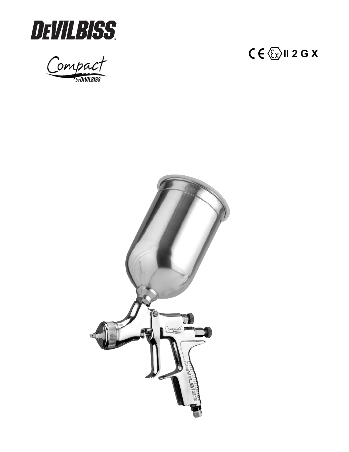
OPERATION MANUAL
ADVANCED-CONVENTIONAL GRAVITY FEED SPRAYGUN
English: Pages 2-9
MANUAL DE OPERACIÓN
COMPACT– PISTOLA PULVERIZADORA CONVENCIONAL
AVANZADO CON ALIMENTACIÓN POR GRAVEDAD
Español: Páginas 10-17
Page 2
Page 2 SB-2-546
IMPORTANT: Read and follow all instructions and SAFETY PRECAUTIONS before
using this equipment.
DESCRIPTION
The Compact Gravity feed Spraygun Kit
complies to ATEX regulations 94/9/EC,
protection level; II 2 G X, Suitable for use
in Zones 1 and 2.
IMPORTANT: These Sprayguns are suit-
able for use with solvent and waterbased
materials. If there is any doubt regarding
the suitability of a specific material contact
your local Distributor or ITWIF direct.
EC DECLARATION OF CONFORMITY
We: ITW Finishing UK, Ringwood Rd,
Bournemouth, Dorset, BH11 9LH, UK, as
the manufacturer of the Spraygun model
Compact, declare, under our sole respon-
sibility, that the equipment to which this
document relates is in conformity with
the following standards or other normative documents:
BS EN 292-1 PARTS 1 & 2: 1991, BS EN
1953: 1999; and thereby conform to the
protection requirements of Council
Directive 98/37/EC relating to Machinery
Safety Directive, and; EN 13463-1:2001,
council Directive 94/9/EC relating to
Equipment and Protective Systems
intended for use in Potentially Explosive
Atmospheres protection level II 2 G X.
B. Holt, General Manager
30th June 2003
ITWIF reserve the right to modify equipment specification without prior notice.
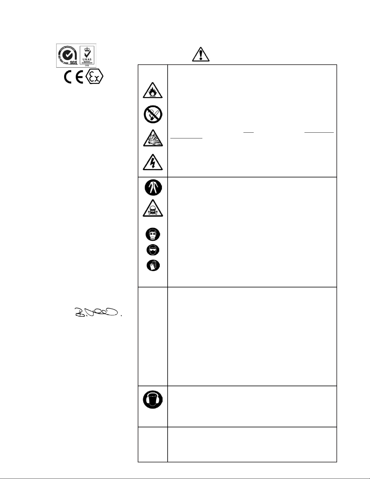
SAFETY WARNINGS
FIRE AND EXPLOSION
Solvents and coating materials can be highly flammable or
combustible when sprayed. ALWAYS refer to the coating material
suppliers instructions and COSHH sheets before using this equipment.
Users must comply with all local and national codes of practice and
insurance company requirements governing ventilation, fire precautions, operation and house-keeping of working areas.
This equipment, as supplied, is NOT
suitable for use with Halogenated
Hydrocarbons.
Static Electricity can be generated by fluid and/or air passing through
hoses, by the spraying process and by cleaning non- conductive parts
with cloths. To prevent ignition sources from static discharges, earth
continuity must be maintained to the spraygun and other metallic
equipment used. It is essential to use conductive air and/or fluid hoses.
PERSONAL PROTECTIVE EQUIPMENT
Toxic vapors – When sprayed, certain materials may be poisonous,
create irritation or be otherwise harmful to health. Always read all
labels and safety data sheets for the material before spraying and
follow any recommendations. If In Doubt, Contact Your Material
Supplier.
The use of respiratory protective equipment is recommended at all
times. The type of equipment must be compatible with the material
being sprayed.
Always wear eye protection when spraying or cleaning the spraygun
Gloves must be worn when spraying or cleaning the equipment.
Training – Personnel should be given adequate training in the safe use
of spraying equipment.
MISUSE
Never aim a spraygun at any part of the body.
Never exceed the max. recommended safe working pressure for the
equipment.
The fitting of non-recommended or non-original spares may create
hazards.
Before cleaning or maintenance, all pressure must be isolated and
relieved from the equipment.
The product should be cleaned using a gun washing machine.
However, this equipment should not be left inside gun washing
machines for prolonged periods of time.
NOISE LEVELS
The A-weighted sound level of sprayguns may exceed 85 dB (A)
depending on the set-up being used. Details of actual noise levels are
available on request. It is recommended that ear protection is worn at
all times when spraying.
OPERATING
Spray Equipment using high pressures may be subject to recoil forces.
Under certain circumstances, such forces could result in repetitive
strain injury to the operator.
Page 3
Page 3SB-2-546
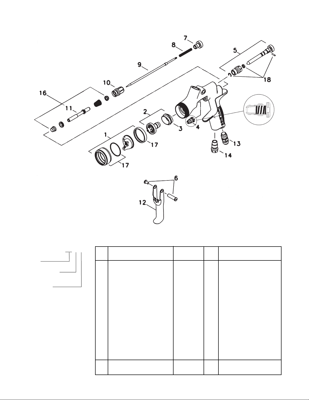
Patent No. 2372465 (GB)
MODEL PART NUMBER
Example: COM-G430-14-02
Aircap
Fluid nozzle size
(14 = 1.4 mm)
00 = No cup
02 = Gravity cup
Ref.
No. Description Part Number Qty. Options
1 Air Cap/Retaining ring COM-430 SP-100-430-K 1
+2 Nozzle SP-200S-**-K 1 14, 18, 22 e.g ** =14 =1.4 mm
+3 Separator SP-626-K5 5
+4 Packing GTI-445-K2 2
5 Spreader Valve SP-403-K 1
6 Stud and Screw GTI-408-K5 5
7 Needle Adjusting Screw SP-614-K 1
+8 Spring SP-622-K5 1
+9 Needle SP-300S-**-K 1 14, 18, 22 e.g ** =14 =1.4 mm
10 Airvalve housing & seal SP-612-K 1
+11 Spindle 1
12 Trigger SP-617-K 1
13 Connector SP-611-K 1
14 Plug SP-637 1
+16 Air Valve Service Kit SPK-101-K 1
17 Retaining Ring and Seals SPK-102-K 1
+18 Clip, Seal and Pin Kit GTI-428-K5 5
23 Air Valve assembly Tool 1
24 Spanner SPN-5 1
Spraygun Service Kit SPK-401-** 1 14, 18, 22 e.g ** =14 =1.4 mm
(parts included marked + )
PARTS LIST
Page 4
Page 4 SB-2-546
INSTALLATION
Important: To ensure that this
equipment reaches you in first
class condition, protective
coatings have been used. Flush
the equipment through with a
suitable solvent before use.
1. Attach air hose to connector (13).
Recommended hose size 8 mm
bore. The hose must be conductive
and electrical bond from the
spraygun to earth should be checked
with an ohmeter. A resistance of less
than 106Ohms is recommended.
2. Air supply should be filtered and
regulated.
3. Attach Cup assembly (22) by
screwing into the Fluid Inlet of the
spraygun. Tighten with a wrench.
OPERATION
1. Mix coating material to manufacturers instructions.
2. Fill the cup with the required amount
of material. Fill to no more than
25mm (1") from the top of the cup.
DO NOT OVERFILL.
3. Attach Cup Lid.
4. Turn needle adjusting screw (7)
clockwise to prevent movement.
5. Turn spreader valve (5) counterclockwise to fully open.
6. Adjust inlet air pressure (For recommended figures see Specifications)
at the gun inlet with the gun triggered. (pressure gauge attachment
shown under Accessories is recommended for this).
7. Turn needle adjusting screw counter
clockwise until first thread shows.
8. Test spray. If the finish is too dry
reduce airflow by reducing air inlet
pressure or by the optional Airflow
Valve (14). Screw the Adjusting
Knob (14) in to reduce pressure.
9. If finish is too wet reduce fluid flow
by turning needle screw (7) clockwise. If atomization is too coarse,
increase inlet air pressure. If too fine
reduce inlet pressure.
10. The pattern size can be reduced by
turning adjusting valve (5) clockwise.
11. Hold gun perpendicular to surface
being sprayed. Arcing or tilting may
result in uneven coating.
12. The recommended spray distance is
150-200 mm (6"-8").
13. Spray edges first. Overlap each
stroke a minimum of 50%. Move gun
at a constant speed.
14. Always turn off air supply and
relieve pressure when gun is not in
use.
PREVENTATIVE MAINTENANCE
1. Turn off air and relieve pressure in
the supply lines, or if using QD
system, disconnect from airline.
2. Remove Cup Lid (20) and empty
coating material into a suitable
container. Clean the gun and cup,
preferably in a gun wash machine.
Clean the cup.
3. Check the breather hole in the Lid
and the Drip Check Lid is not
blocked.
4. Remove air cap (1) and clean. If any
of the holes in the cap are blocked
with coating material use a toothpick
to clean. Never use metal wire which
could damage the cap and produce
distorted spray patterns
5. Ensure the tip of the nozzle (2) is
clean and free from damage. Build
up of dried paint can distort the
spray pattern.
6. Lubrication – stud/screw (6), needle
(9) and air valve (11) should be oiled
each day.
REPLACEMENT OF PARTS
Nozzle (2) and Needle (9) – Remove parts
in the following order: 7, 8, 9, 1 and 2.
Replace any worn or damaged parts and
re-assemble in reverse order.
Recommended tightening torque for
nozzle (2) 9.5-12 Nm (80-100 lbf in).
Packing – Remove parts 7, 8, 9. Unscrew
cartridge (4). Fit new cartridge finger
tight. Re-assemble parts 9, 8, and 7 and
tighten cartridge (4) with spanner sufficient to seal but to allow free movement
of needle. Lubricate with gun oil.
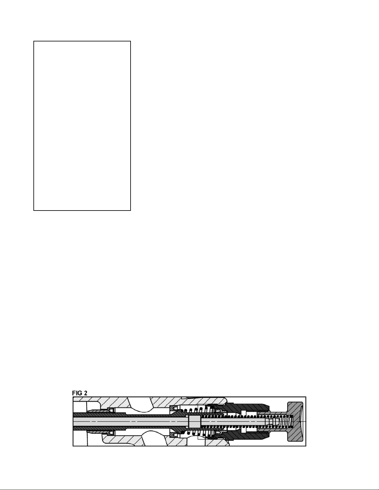
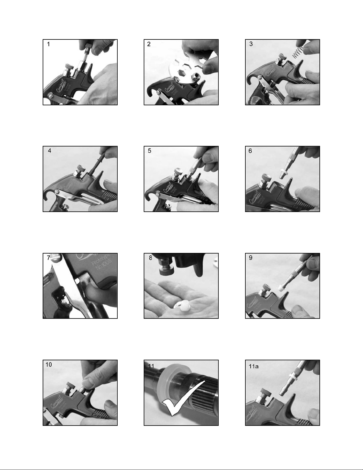
Air Valve Seal Kit (16) – (Refer to photos
1 to 28 and fig 2)
Spreader valve (5) – Caution: always
ensure that the valve is in the fully open
position by turning screw fully counterclockwise before fitting to body.
SPECIFICATION
Air supply connection:
Universal 1/4" BSP and NPS
Maximum static Air inlet pressure:
P1= 12 bar (175 psi)
Nominal gun Air inlet pressure
with gun triggered:
3 bar (44 psi)
Maximum Service temperature: 40°C
Gun Weight: 412 g
MATERIALS OF CONSTRUCTION
Gun body: Anodized Aluminum
Nozzle: Stainless Steel
Needle: Stainless Steel
Fluid Inlet / Fluid Passages:
Anodized Aluminum
Trigger: Nickel Plated Steel
Page 5
Page 5SB-2-546
1. Remove Adjusting Knob (7),
Spring (8), and Needle (9).
2. Loosen Housing (10). 3. Remove Housing (10) and
Airvalve Spring.
4. Remove Valve (11). 5. Using Service Tool SPN-7,
engage groove behind the
Valve Seat.
6. Remove Valve Seat.
7. Push out the Front Airvalve
Seal with a finger.
8. Turn the Gun upside down
and let the Seal fall out.
9. Fit New Front Seal to Service
Tool.
10. Fit new Seal to gunbody and
press firmly to ensure Seal is
engaged.
11. Fit New Valve Seat to
Service Tool. Groove must
face outwards.
Page 6
Page 6 SB-2-546
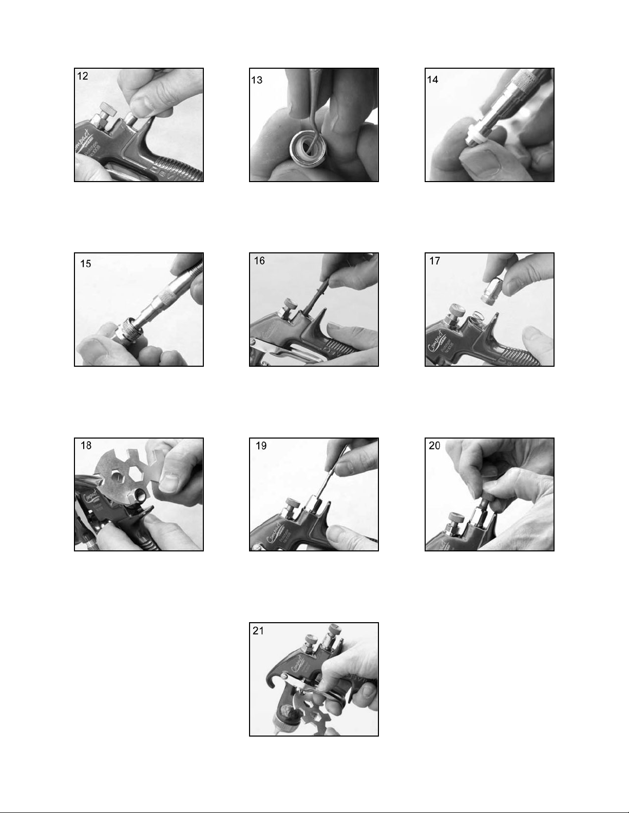
12. Fit Valve Seat to Gunbody. 13. Remove Rear Airvalve Seal
from housing (10) with a
hooked instrument.
14. Fit new Seal to Service Tool.
15. Fit Seal to Housing (10). 16. Replace Valve (11). 17. Replace Valve Spring and
screw in Housing (10).
18. Tighten Housing. 19. Fit Needle (9). 20. Fit Spring (8) and Knob (7).
21. Adjust Needle Packing (4)
with Spanner sufficient to
seal but to allow free movement of needle. Lubricate
with gun oil.
Page 7

Page 7SB-2-546
*Most common problem.
Left or right side horn holes plugged.
Dirt on left or right side of fluid tip.
Remedies for the top-heavy, bottom-heavy, right-heavy, and left-heavy patterns:
1. Determine if the obstruction is on the air cap or the fluid tip. Do this by making a test
spray pattern. Then, rotate the cap one-half turn and spray another pattern. If the defect
is inverted, obstruction is on the air cap. Clean the air cap as previously instructed.
2. If the defect is not inverted, it is on the fluid tip. Check for a fine burr on the edge of the
fluid tip. Remove with #600 wet or dry sand paper.
3. Check for dried paint just inside the opening; remove by washing with solvent.
Fluid flow too high for atomization air.
Material flow exceeds air cap's capacity.
Spreader adjustment valve set too low.
Atomizing pressure too low.
Material too thick.
Atomization air pressure too high.
Fluid flow too low.
Spreader adjusting valve set too high.
*Loose or damaged fluid tip/seat.
Baffle seal installed incorrectly.
Material level too low.
Container tipped too far.
Obstruction in fluid passage.
Dry or loose fluid needle packing nut.
Spreader adjustment screw not seating
properly.
Air cap retaining ring loose.
No air pressure at gun.
Fluid needle adjusting screw not open
enough.
Fluid too heavy for gravity feed.
Fluid tip not tight.
Cup lid loose.
Dirty threads on cup or lid.
Cracked cup or lid.
Inadequate material flow.
Low atomization air pressure.
Too much atomization air pressure.
Gun too far from work surface.
Improper stroking (arcing, gun motion too
fast).
Too much or too fast-drying thinner.
Too much atomization air pressure.
Air pressure too high.
Gun tip too far from work surface.
Gun motion too fast.
Gun out of adjustment.
Packing nut loose.
Packing worn or dry.
Packing nut too tight.
Dry packing.
Fluid tip or needle worn or damaged.
Foreign matter in tip.
Fluid needle spring broken.
Wrong size needle or tip.
Clean. Ream with non-metallic point.
Clean.
Clean.
Clean. Ream with non-metallic point.
Clean.
Horn holes plugged.
Obstruction on top or bottom of fluid tip.
Cap and/or tip seat dirty.
TROUBLESHOOTING
CONDITION CAUSE CORRECTION
Heavy top or
bottom pattern
Heavy right or left
side pattern
Heavy center pattern
Split spray pattern
Jerky or fluttering spray
Unable to get round spray
Will not spray
Paint bubbles in cup
Fluid leaking or dripping from
cup lid
Starved spray pattern
Excessive overspray
Excessive fog
Dry spray
Fluid leaking from packing nut
Fluid leaking or dripping from
front of gun
Balance air pressure and fluid flow. Increase
spray pattern width with spreader adjustment
valve.
Thin or lower fluid flow.
Adjust.
Increase pressure.
Thin to proper consistency.
Reduce at transformer or gun.
Increase fluid flow (increases gun handling
speed).
Adjust.
Tighten or replace.
Install per directions.
Refill.
Hold more upright.
Backflush with solvent.
Lubricate or tighten.
Clean or replace.
Tighten.
Check air supply and air lines, blow out gun
air passages.
Open fluid needle adjusting screw.
Thin material and/or change to larger tip size.
Tighten tip to 12-15 ft-lbs.
Push in or tighten lid.
Clean.
Replace cup and lid.
Back fluid adjusting screw out to first thread,
or change to larger tip size.
Increase air pressure and rebalance gun.
Reduce pressure.
Adjust to proper distance.
Move at moderate pace, parallel to work
surface.
Remix properly.
Reduce pressure.
Reduce air pressure.
Adjust to proper distance.
Slow down.
Adjust.
Tighten, do not bind needle.
Replace or lubricate.
Adjust.
Lubricate.
Replace tip and needle.
Clean.
Replace.
Replace.
Page 8

Page 8 SB-2-546
Tighten.
Replace cup gasket.
Clean.
Adjust gun or reduce fluid flow.
Mix properly or apply light coats.
Hold gun at right angle to work and
adapt to proper gun technique.
Check distance. Normally approx. 8".
Reduce air pressure and check spray pattern.
Follow paint manufacturer's mixing instrs.
Check distance. Normally approx. 8".
Too much material coarsely atomized.
Increase air pressure or reduce fluid flow.
Follow paint manufacturer's mixing instrs.
Properly clean and prepare.
Cup loose on gun.
Cup gasket worn or missing below cup.
Cup threads dirty.
Too much material flow.
Material too thin.
Gun tilted on an angle, or gun
motion too slow.
Gun too far from surface.
Too much air pressure.
Improper thinner being used.
Gun too close to surface.
Air pressure too low.
Improper thinner being used.
Material not properly mixed.
Surface rough, oily, dirty.
TROUBLESHOOTING (continued)
CONDITION CAUSE CORRECTION
Fluid dripping or leaking from
bottom of cup
Runs and sags
Thin, sandy coarse finish drying
before it flows out
Thick, dimpled finish "orange peel"
Page 9

Page 9SB-2-546
NIOSH-Certified for respiratory protection in
atmospheres not immediately dangerous to life.
Consists of : 1 - Piercing Tool,
48 - Disposable Liners, 48 - Drain Bushings
OMX-70-K48 Paint Cup Liner Kit
Allows quick & easy clean-up.
(1) Wall mount bracket
included with GH-407.
Holds standard paint
cups, gravity feed guns and
cups, and paint filters.
GH-407
Gun Holder
Gun holders are
made to hold standard paint cups, gravity feed guns and
cups, and paint filters.
GH-505
Gun Holder
Cleaning Brushes
42884-214-K5 (3/8")
42884-215-K10 (5/8")
These brushes are
helpful in cleaning
threads and recesses
of gun body.
Compatible with all paint materials;
contains no silicone or petroleum
distillates to contaminate paint.
MSDS Sheet available upon request.
Contains all necessary tip, hose and
nut sizes used on or
with gun.
SPN-5 Wrench
Scrubs®are a premoistened hand cleaner
towel for painters, body
men and mechanics that
go where you go and no
water is needed.
29-3100-K6 Scrubs
®
Hand Cleaner Towels
HC-4700
1/4" NPT(F)
HC-1166
1/4" NPT(M)
HC-4699
1/4" NPT(M)
HC-4419
1/4" NPS(F)
Industrial Quick Connects
for HVLP Guns (Air)
Spray Gun Lube
SSL-10-K12 (2 oz. bottle)
Fits Compact gun only.
Compatible with DeVilbiss
high flow quick disconnects.
MPV-60-K3
Air Inlet Swivel
(Pack of 3)
Installs into gun to enable
user to control and reduce
air usage at the gun.
Replaces SP-637 plug.
SP-402-K
Air Adjusting Valve
Paint Spray Respirators
40-141 (Sm) 40-128 (Med) 40-143 (Lg)
ACCESSORIES
These gravity feed cups
are designed to be used
with EXL, FLG, GFG,
GFHV, GTI or Compact
gravity feed spray guns.
DGI-501-PSI-USA
Digital
Pressure Gauge
Digital pressure
gauge for precise
pressure control at
the gun.
GFC-501 (Acetal) 20 Oz. Cup
GFC-502 (Aluminum) 1-Liter Cup
Gravity Feed Cups
HAV-500 does not
have pressure gauge.
Use to control air
usage at gun.
HAV-500 OR
HAV-501
Adjusting Valve
(HAV-501 SHOWN)
Page 10

Página 10 SB-2-546
IMPORTANTE: Lea y siga todas las
instrucciones y Precauciones de Seguridad
antes de utilizar este equipo.
DESCRIPCIÓN
El Kit de Pistola Pulverizadora por
Gravedad Compact cumple las normas
ATEX 94/9/CE, nivel de protección; II 2 G X,
Adecuado para el uso en las Zonas 1 y 2.
IMPORTANTE: Estas pistolas pulver-
izadoras son apropiadas para el uso con
materiales al agua y a base de disolventes. Si tiene alguna duda respecto a la
idoneidad de un material específico,
póngase en contacto con su Distribuidor
local o directamente con ITWIF.
DECLARACIÓN DE CONFORMIDAD CE
Nosotros: ITW Finishing UK, de
Ringwood Rd, Bournemouth, Dorset,
BH11 9LH, Reino Unido, como fabricantes
de la Pistola pulverizadora modelo
Compact, declaramos bajo nuestra exclu-
siva responsabilidad que el equipo al que
se refiere este documento cumple los
siguientes estándares o normas:
BS EN 292-1 PARTES 1 y 2: 1991, BS EN
1953:1999; y que por tanto cumple los
requisitos de protección de la Directiva del
Consejo 98/37/CE relativa a la Directiva
sobre Seguridad de las Máquinas y EN
13463-1:2001, Directiva del Consejo
94/9/CE relativa a Equipos y sistemas de
protección diseñados para ser utilizados
en atmósferas potencialmente explosivas
nivel de protección II 2 G X.
B. Holt, Director General
30/6/2003
ITW Finishing Systems and Products se
reserva el derecho a modificar las especificaciones del equipo sin previo aviso.
ADVERTENCIAS DE SEGURIDAD
INCENDIO Y EXPLOSIÓN
Los disolventes y los materiales de recubrimiento pueden ser altamente inflamables o combustibles al pulverizarse. Consulte SIEMPRE las instrucciones del
fabricante del material de recubrimiento y las hojas COSHH antes de utilizar
este equipo.
Los usuarios deben cumplir la normativa nacional y local y los requisitos de las
compañías de seguros respecto a ventilación, precauciones contraincendios,
operación y mantenimiento de las zonas de trabajo.
Este equipo, tal y como se suministra, NO
es adecuado para su uso con
Hidrocarburos Halogenados
.
La Electricidad Estática puede ser generada por el paso de fluido y/o aire por los
manguitos, por el proceso de pulverización y por la limpieza de piezas no
conductoras con paños. Para impedir que las descargas estáticas produzcan
fuentes de ignición, debe mantenerse la continuidad de tierra a la pistola pulverizadora y a otros equipos metálicos utilizados. Es imprescindible utilizar
manguitos de aire y/o fluido que sean conductores de electricidad.
EQUIPO DE PROTECCIÓN PERSONAL
Vapores tóxicos - Al pulverizarse, ciertos materiales pueden ser tóxicos, crear
irritación o ser dañinos para la salud de otra forma. Lea siempre todas las
etiquetas y hojas de datos de seguridad del material antes de pulverizar, y siga
cualquier recomendación. En caso de Duda, Póngase en Contacto con el
Proveedor del Material.
Se recomienda el uso de equipos de protección respiratoria en todo momento. El
tipo de equipo debe ser compatible con el material que se está pulverizando.
Lleve siempre protección ocular al pulverizar o al limpiar la pistola.
Deben llevarse guantes al pulverizar o al limpiar la pistola.
Formación - El personal debe recibir una formación adecuada en el uso seguro
de equipos de pulverización.
MAL USO
No apunte nunca con una pistola de pulverización a ninguna parte del cuerpo.
No supere nunca la presión máxima de operación segura recomendada del
equipo.
El acoplamiento de piezas de repuesto no recomendadas o no originales puede
crear riesgos.
Antes de realizar limpieza o mantenimiento, toda presión debe aislarse y aliviarse
en el equipo.
El producto debe ser limpiado usando una máquina para lavar pistolas. No
obstante, este equipo no debe dejarse dentro de una máquina de lavar pistolas
durante periodos de tiempo prolongados.
NIVELES SONOROS
El nivel sonoro con ponderación A de las pistolas de pulverización puede superar
los 85 dB(A) dependiendo de la configuración utilizada. Los detalles de niveles
sonoros reales están disponbles previa petición. Se recomienda llevar protección
acústica en todo momento durante la pulverización.
OPERACIÓN
Los Equipos de Pulverización que funcionan a alta presión pueden verse
sometidos a fuerzas de retroceso. Bajo determinadas circunstancias, dichas
fuerzas podrían provocar al operador lesiones por esfuerzo repetitivo (RSI).
Page 11

Página 11SB-2-546
Patente Nº 2372465 (GB)
MODELO-NÚMERO PIEZA
Ejemplo: COM-G430-14-02
Casquillo de aire
Diámetro del pico
de fluido
(14 = 1.4 mm)
00 = Sin taza
02 = Taza de gravedad
Nº Número
Ref. Descriptión de Pieza Cant Opciones
1Casquillo de aire / Anillo de SP-100-430-K 1
retención COM-430
+2 Pico de fluido SP-200S-**-K 1 14, 18, 22 ej. ** =14 =1.4 mm
+3 Separador SP-626-K5 5
+4 Empaquetadura GTI-445-K2 2
5 Válvula dispersora SP-403-K 1
6 Espiga y tornillo GTI-408-K5 5
7 Tornillo de ajuste de la aguja SP-614-K 1
+8 Muelle SP-622-K5 1
+9 Aguja SP-300S-**-K 1 14, 18, 22 ej. ** =14 =1.4 mm
10 Alojamiento de la válvula de aire SP-612-K 1
& junta
+11 Vástago 1
12 Gatillo SP-617-K 1
13 Conector SP-611-K 1
14 Tapón SP-637 1
+16 Kit de mantenimiento de la SPK-101-K 1
válvula de aire
17 Retén y juntas SPK-102-K 1
+18 Kit de clip, junta y perno GTI-428-K5 5
23 Herramienta para el conjunto de
la válvula de aire 1
24 Llave SPN-5 1
Kit de Mantenimiento de SPK-401-** 1 14, 18, 22 ej. ** =14 =1.4 mm
la Pistola Pulverizadora
(piezas incluidas marcadas con + )
LISTA DE PIEZAS
Page 12

Página 12 SB-2-546
INSTALACIÓN
Importante: Para asegurarse
de que este equipo llega a
usted en condiciones óptimas,
se han utilizado recubrimientos
protectores. Enjuague el
equipo con un disolvente
adecuado antes de su uso.
1. Acople el manguito de aire al
conector (13). Tamaño de manguito
recomendado: 8 mm diám. interior.
El manguito debe ser conductor de
electricidad y la conexión eléctrica
entre la pistola pulverizadora y tierra
debe verificarse con un ohmímetro.
Se recomienda una resistencia de
menos de 106Ω. El suministro de aire
debe estar filtrado y regulado.
2. El suministro de aire debe estar
filtrado y regulado.
3. Acople el conjunto de la Cubeta (22)
enroscándolo en la entrada de fluido
de la pistola pulverizadora. Apriete
cuando haya entrado del todo.
OPERACIÓN
1. Mezcle el material de recubrimiento
siguiendo las instrucciones del fabricante.
2. Llene la copa con la cantidad
requerida de material. No llene a
menos de 25 mm de la parte superior de la copa. NO LLENE
DEMASIADO.
3. Acople la tapa de la cubeta.
4. Gire el tornillo de ajuste de la aguja
(7) en el sentido de las agujas del
reloj para impedir que se mueva.
5. Gire la válvula de dispersión (5) en el
sentido contrario a las agujas del
reloj hasta que esté abierta del todo.
6. Ajuste la presión de aire de entrada
(ver valores recomendados en las
Especificaciones) en la entrada de la
pistola con el gatillo apretado. con el
gatillo apretado (se recomienda
utilizar para ello el manómetro
mostrado en Accesorios).
7. Gire el tornillo de ajuste de la aguja
en el sentido contrario a las agujas
del reloj hasta que se vea la primera
rosca.
8. Haga una prueba de pulverización.
Si el acabado es demasiado seco,
reduzca el caudal de aire reduciendo
la presión de entrada de aire o mediante la Válvula de Caudal de Aire
opcional (14). Gire el Pomo de
Ajuste (14) hacia dentro para reducir
la presión.
9. Si el acabado es demasiado
húmedo, reduzca el caudal de fluido
girando el tornillo de la aguja (7) en
el sentido de las agujas del reloj o
reduciendo la presión del fluido. Si
la atomización es demasiado
gruesa, aumente la presión de
entrada de aire. Si es demasiado
fina, reduzca la presión de entrada.
10. El tamaño del patrón puede
reducirse ajustando la válvula (5) en
el sentido de las agujas del reloj.
11. Sujete la pistola perpendicular a la
superficie a pulverizar. Pulverizar en
arcos o con la pistola inclinada
puede producir un recubrimiento
desigual.
12. La distancia de pulverización
recomendada es de 150 - 200 mm.
13. Pulverice primero los bordes.
Solape cada pasada el 50% como
mínimo. Mueva la pistola a una
velocidad constante.
14. Cierre siempre el suministro de aire
y alivie la presión cuando la pistola
no se esté utilizando.
MANTENIMIENTO PREVENTIVO
1. Cierre el suministro de aire y alivie la
presión en los manguitos de suministro, o si utiliza el sistema QD,
desconéctelo del manguito de aire.
2. Retire la Tapa de la cubeta (20) y
vacíe el material de recubrimiento
en un recipiente apropiado. Limpie
la pistola y la cubeta, preferentemente en una máquina de lavado de
pistolas. Limpie la cubeta.
3. Compruebe que el orificio de ventilación de la tapa y de la tapa antigoteo no está obstruido.
4. Retire el casquillo de aire (1) y
límpielo. Si alguno de los orificios
del casquillo está obstruido con
material de recubrimiento, utilice un
palillo de dientes para limpiarlo. No
utilice nunca un alambre metálico,
porque podría dañar el casquillo y
producir patrones de pulverización
distorsionados.
5. Asegúrese de que la punta de la
boquilla (2) está limpia y libre de
desperfectos. Una acumulación de
pintura seca puede distorsionar el
patrón de pulverización.
6. Lubricación – la espiga/tornillo (6), la
aguja (9) y la válvula de aire (11)
deben lubricarse con aceite cada dia.
SUSTITUCIÓN DE PIEZAS
Boquilla (2) y Aguja (9) – Retire las piezas
en el siguiente orden: 7, 8, 9, 1 y 2.
Sustituya cualquier pieza desgastada o
dañada y vuelva a montar las piezas en
orden inverso. Par de apriete recomendado para la boquilla (2) 9,5-12 Nm (80100 pies-libra/pulgada).
Guarnición – Retire las piezas 7, 8, 9.
Desenrosque el cartucho (4). Coloque un
cartucho nuevo y apriete con los dedos
solamente. Vuelva a montar las piezas 9,
8 y 7 y apriete el cartucho (4) con una
llave, lo suficiente para hacer sello pero
dejando que la aguja se desplace libremente. Lubrique con aceite para pistolas.
Kit de Junta de la Válvula de Aire (16) –
(Ver FIG 2 y fotos 1 a 28).
Válvula Dispersora (5) – Precaución:
asegúrese siempre de que la válvula está
en posición completamente abierta
girando el tornillo en el sentido contrario
a las agujas del reloj hasta que haga tope
antes de instalarla en el cuerpo de la
pistola.
ESPECIFICACIÓN
Conexión del suministro de aire :
Universal 1/4" BSP and NPS
Presión estática máxima de entrada
de aire: P1= 12 bar (175 psi)
Presión nominal de entrada de aire
en la pistola – con el gatillo apretado:
3 bar (44 psi)
Temperatura Máxima de uso: 40°C
Peso de pistola: 412 g
MATERIALES DE CONSTRUCCIÓN
Cuerpo de la pistola: Aluminio
anodizado
Boquilla: Acero inoxidable
Aguja: Acero inoxidable
Entrada de fluido / Conductos de fluido:
Aluminio anodizado
Gatillo: Acero niquelado
Page 13

Página 13SB-2-546
1. Retire el pomo de ajuste (7),
el muelle (8), y la aguja (9).
2. Afloje el alojamiento (10). 3. Retire el alojamiento (10) y
el muelle de la válvula de
aire.
4. Retire la válvula (11). 5. Usando la herramienta de
manteni-miento SPN-7,
enganche la muesca detrás
del asiento de la válvula.
6. Retire el asiento de la
válvula.
7. Haga salir la junta delantera
de la válvula de aire empujando con el dedo.
8. Ponga la pistola boca abajo
y deje que se caiga la junta.
9. Instale una junta delantera
nueva en la herramienta de
mantenimiento.
10. Coloque la junta nueva sobre el
cuerpo de la pistola y empuje
firmemente para asegurarse de
que la junta quede correctamente colocada.
11. Coloque un asiento de
válvula nuevo en la
herramienta de mantenimiento.
Page 14

Página 14 SB-2-546
12. Coloque el asiento de
válvula en el cuerpo de la
pistola.
13. Retire la junta de la válvula
de aire del alojamiento (10)
con un instrumento que
tenga gancho.
14. Instale una junta nueva en la
herramienta de mantenimiento.
15. Coloque la junta en el
alojamiento (10).
16. Vuelva a colocar el husillo
(11).
17. Vuelva a colocar el muelle
de la válvula y el tornillo en
el alojamiento (10).
18. Apriete el alojamiento. 19. Coloque la aguja (9). 20. Instale el muelle (8) y el
pomo (7).
21. Ajuste la guarnición de la aguja (4) con
una llave lo suficiente para hacer sello
pero permitiendo que se desplace la
aguja. Lubrique con aceite para pistolas.
Page 15

Página 15SB-2-546
*Problemas más comunes.
Agujeros en el lado izquierdo o derecho de la
horquilla obstruidos.
Suciedad en el lado izquierdo o derecho de la
punta del líquido.
Corrección de los patrones pesados en la parte superior, inferior, el lado derecho e izquierdo.
1. Determine si la obstrucción está en el casquillo de aire o en la punta de fluido. Realice esto haciendo
una prueba del patrón de pulverización. Luego gire el casquillo media vuelta y pulverice con otro
patrón. Si se invierte el defecto, la obstrucción se encuentra en el casquillo de aire. Limpie el
casquillo de aire siguiendo las instrucciones previas.
2.
Si el defecto no se invierte, la obstrucción se encuentra en la punta de fluido. Verifique si hay una
pequeña protuberancia en el borde de la punta de fluido. Quítela con papel de lija #600 húmedo o seco.
3. Verifique si hay pintura seca dentro de la abertura; elimínela lavándola con disolvente.
El fluido fluye demasiado alto para el aire de
atomización.
El flujo del material sobrepasa la capacidad del
casquillo de aire.
El ajuste de la válvula dispersora es muy bajo.
La presión de atomización es muy baja.
El material es muy espeso.
La presión de aire de atomización es muy alta.
El fluido fluye muy bajo.
El ajuste de la válvula dispersora es muy alto.
*La punta/el asiento del fluido está flojo o dañado.
La junta deflectora fue instalada incorrectamente.
El nivel del material es muy bajo.
El recipiente se inclinó mucho.
Obstrucción en el conducto del fluido.
La tuerca de la empaquetadura de la aguja de
fluido seca o floja.
El tornillo de ajuste del dispersador no está
alojado debidamente.
El anillo de retención del casquillo de aire está flojo.
No hay presión de aire en la pistola.
El tornillo de ajuste de la aguja de fluido no está
lo suficientemente abierto.
El fluido es muy pesado para la alimentación
por gravedad.
La punta de fluido no está apretada.
La tapa de la cubeta está floja.
Roscas sucias en la cubeta o tapa.
Cubeta o tapa agrietada.
Flujo inadecuado del material.
Presión de aire de atomización baja.
Demasiada presión de aire de atomización.
La pistola está muy alejada de la superficie de trabajo.
Carrera indebida (formación de arco, el desplazamiento de la pistola es muy rápido).
Demasiado diluyente o diluyente de secado
muy rápido.
Demasiada presión de aire de atomización.
Presión de aire muy alta.
Punta de pistola muy alejada de superficie de trabajo.
El desplazamiento de la pistola es muy rápido.
Pistola desajustada.
Tuerca de la empaquetadura floja.
Empaquetadura gastada o seca.
Tuerca de la empaquetadura muy apretada.
Empaquetadura seca.
Punta de fluido o aguja gastada o dañada.
Materias foráneas en la punta.
Muelle de la aguja del fluido roto.
Aguja o punta de tamaño inadecuado.
Limpie. Escariar con punta no metálica.
Limpie.
Limpie.
Limpie. Escariar con punta no metálica.
Limpie.
Agujeros de la horquilla obstruidos.
Obstrucción en la parte superior o inferior de la
punta de fluido.
Casquillo y/o asiento de la punta está sucio.
LOCALIZACIÓN Y REPARACIÓN DE PROBLEMAS
CONDICIÓN CAUSA CORRECCIÓN
Patrón pesado en
la parte superior
o inferior
Patrón pesado en
el lado derecho
o izquierdo
Patrón pesado
en el centro
Patrón de pulverización
dividida
Pulverización entrecortada o
con vibraciones
Imposibilidad de obtener
pulverización redondeada
No pulveriza
Burbujas de pintura en la cubeta
El fluido se escapa o gotea de la tapa
de la cubeta
Patrón de pulverización subalimentada
Sobrepulverización excesiva
Nebulización excesiva
Pulverización seca
Escape de fluido por la tuerca de la
empaquetadura
Escape o goteo de fluido por la parte
delantera de la pistola
Equilibre la presión de aire y el flujo de fluido.
Aumente el ancho del patrón de pulverización con la
válvula de ajuste del dispersador.
Diluya o baje el flujo de fluido.
Ajuste.
Aumente la presión.
Diluya hasta lograr la consistencia adecuada.
Reduzca la presión en el transformador o en la pistola.
Aumente el flujo de líquido (aumente la velocidad de
manipulación de la pistola).
Ajuste.
Apriete o reemplace.
Instálelo de acuerdo con las instrucciones.
Vuelva a llenar.
Sosténgalo de forma más vertical.
Limpie con disolvente.
Lubrique o apriete.
Limpie o reemplace.
Apriete.
Verifique el suministro de aire y las líneas de aire,
limpie con aire comprimido los conductos de aire de
la pistola.
Abra el tornillo de ajuste de la aguja de fluido.
Diluya el material y/o cambie la punta por una más
grande.
Apriete la punta a 12-15 libras-pies.
Empuje o apriete la tapa.
Limpie.
Reemplace la cubeta o la tapa.
Retuerza el tornillo de ajuste de fluido hasta la
primera rosca o cambie la punta por una más grande.
Aumente la presión de aire y reequilibre la pistola.
Reduzca la presión.
Ajuste hasta la distancia adecuada.
Desplace la pistola a un ritmo moderado, paralelo a
la superficie de trabajo.
Vuelva a mezclar el diluyente debidamente.
Reduzca la presión.
Reduzca la presión de aire.
Ajuste hasta la distancia adecuada.
Reduzca la velocidad.
Ajuste.
Apriete, no bloquee la aguja.
Reemplace o lubrique.
Ajuste.
Lubrique.
Reemplace la punta y la aguja.
Limpie.
Reemplace.
Reemplace.
Page 16

Página 16 SB-2-546
Apriete.
Reemplace la guarnición de la cubeta.
Limpie.
Ajuste la pistola o reduzca el flujo de fluido.
Mezcle debidamente o aplique capas livianas.
Sostenga la pistola en un ángulo correcto para
trabajar y adáptela a una técnica debida.
Verifique la distancia. Normalmente, aprox. 8 pulg.
Reduzca la presión de aire y verifique el patrón de
pulverización.
Siga las instrucciones de mezclado del fabricante de la pintura.
Verifique la distancia. Normalmente, aprox. 8 pulg.
Demasiado material áspero fue atomizado.
Aumente la presión de aire o reduzca el flujo de fluido.
Siga las instrucciones de mezclado del fabricante de
la pintura.
Limpie y prepare debidamente.
Cubeta floja en la pistola.
Guarnición de la cubeta gastada o falta
debajo de la cubeta.
Roscas de la cubeta sucias.
Demasiado flujo de material.
Material demasiado diluido.
Pistola inclinada en ángulo o se desplaza
muy despacio.
Pistola muy lejos de la superficie.
Demasiada presión de aire.
Se está empleando un diluyendo inadecuado.
Pistola muy cerca de la superficie.
Presión de aire muy baja.
Se está empleando un diluyente inadecuado.
No se ha mezclado debidamente el material.
Superficie áspera, aceitosa o sucia.
LOCALIZACIÓN Y REPARACIÓN DE PROBLEMAS (continuará)
CONDICIÓN CAUSA CORRECCIÓN
El fluido se escapa o gotea desde la parte
inferior de la cubeta.
Se corre
Acabado rugoso arenoso, fino, que se
seca antes de fluir.
Acabado grueso, no uniforme, como el de
una “cáscara de naranja”.
Page 17

Página 17SB-2-546
Certificados por NIOSH para protección respiratoria en atmósferas que no implican riesgo
inmediato para la vida.
Compuesto por: 1 herramienta perforadora,
48 – forros desechables, 48 – Boquillas
de descarga.
Kit de forros de cubetas de pintura OMX-70-K48
Permite la limpieza rápida y fácil
(1) Soporte de montaje
mural incluido con GH-407.
Sostiene cubetas de
pintura estándares, pistolas
alimentadas por gravedad y
cubetas y filtros de pintura.
GH-407
Soporte de pistola
Los soportes de pistola se
fabrican para sostener cubetas
de pintura estándares, pistolas
alimentadas por gravedad
cubetas y filtros de pintura.
GH-505
Soporte de pistola
Cepillos de limpieza
42884-214-K5-(3/8 de pulg.)
42884-215-K10-(5/8 de pulg.)
Estos cepillos ayudan
a limpiar las roscas y
los lugares ocultos del
cuerpo de la pistola.
Compatible con todos los materiales
de pintura; no contiene destilados de
silicona ni petróleo que contaminen la
pintura. Hoja de Datos de Seguridad de
los Materiales (MSDS, por sus siglas
en inglés) disponible previa solicitud.
Contiene todo los
tamaños necesarios
de punta, manguito
y tuerca utilizados
en o con la pistola.
Llave SPN-5
Scrubs®son toallas
prehumedecidas para que
pintores, encargados de
carrocería y mecánicos se
limpien las manos. Van
donde usted vaya y no se
necesita agua.
29-3100-K6 Scrubs
®
Toallas para limpiarse las manos
HC-4700
1/4" de pulg.
NPT(F)
HC-1166
1/4" de pulg.
NPT(M)
HC-4699
1/4" de pulg.
NPT(M)
HC-4419
1/4" de pulg.
NPS(F)
Dispositivos de conexión rápida industri-
ales para Pistolas HVLP (de aire)
Lubricante de pistola pulverizadora
SSL-10-K12 (botella de 2 oz.)
Para pistolas compactas únicamente.
Compatible con dispositivos de
desconexión rápida de alto flujo
DeVilbiss.
MPV-60-K3
Articulación giratoria
de entrada de aire
(paquete de 3)
Instálela en la pistola para
permitir al usuario controlar
y reducir el uso de aire en
la pistola. Reemplaza el
tapón SP-637
SP-402-K
Válvula reguladora de aire
Respiradores para pulverizadores de pintura
40-141 (pequeño) 40-128 (mediano)
40-143 (grande)
ACCESORIOS
Estas cubetas alimentadas por
gravedad son diseñadas para
ser usadas con pistolas
pulverizadoras EXL, FLG,
GFG, GFHV, GTI o Compactas.
DGI-501-PSI-USA
Manómetro digital
Manómetro digital
para un control
preciso de la presión
en la pistola.
Cubeta GFC-501 (acetal)
Cubeta de 1 litro GFC-502 (aluminio)
Cubetas alimentadas por gravedad
HAV-500 no tiene
manómetro. Se utiliza
para controlar el uso
del aire en la pistola.
HAV-500 O
HAV-501
Válvula reguladora
(HAV-501-MOSTRADA)
Page 18

Page 18 SB-2-546
NOTES
Page 19

Página 19SB-2-546
NOTAS
Page 20

Page 20 SB-2-546
ITW Industrial Finishing
DeVilbiss has authorized distributors throughout the world. For technical assistance or the distributor nearest you, see listing below.
U.S./Canada Technical Service Office:
195 Internationale Blvd., Glendale Heights, IL 60139
Toll-Free Telephone: 1-888-992-4657 (U.S.A. and Canada only)
Toll-Free Fax: 1-800-368-8401
DeVilbiss Worldwide Sales and Service Listing: www.devilbiss.com
WARRANTY
This product is covered by DeVilbiss' 1 Year Limited Warranty.
11/06 ©2006 Illinois Tool Works Inc. All rights reserved. Printed in U.S.A.
 Loading...