

Page 1
SERVICE MANUAL
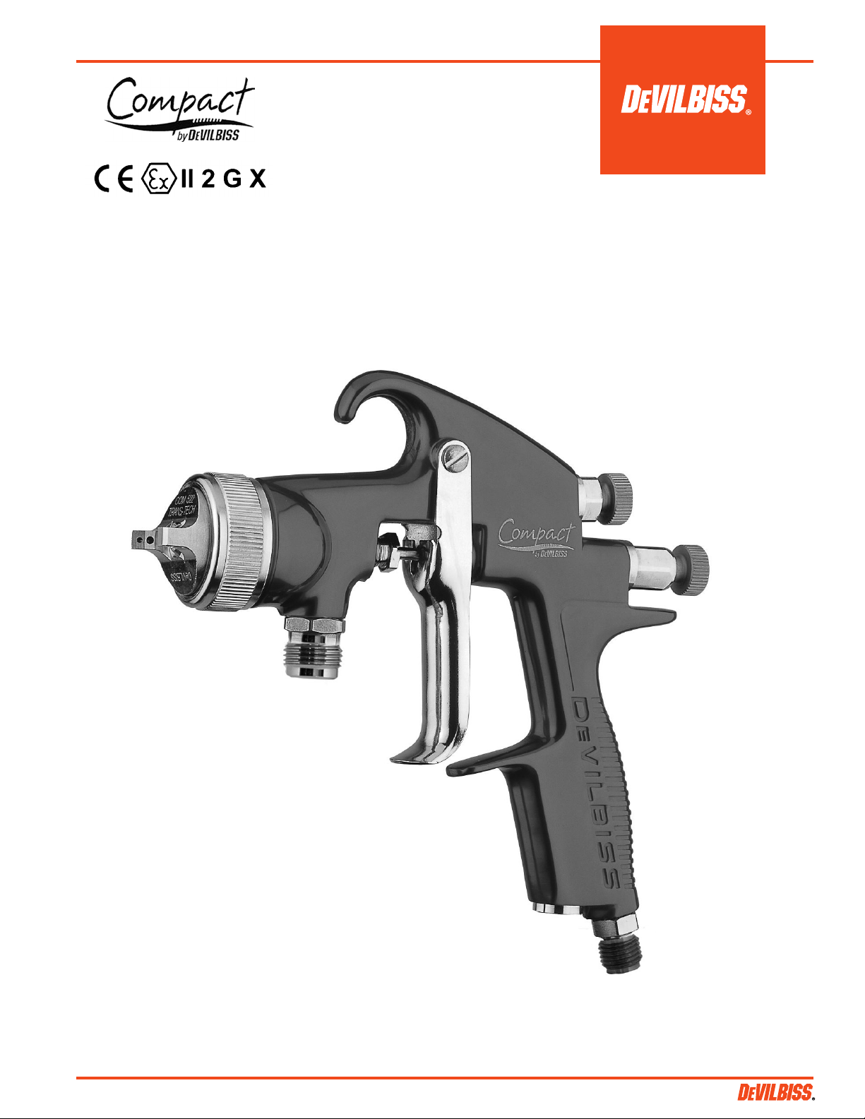
OPERATION MANUAL
HVLP PRESSURE / SIPHON FEED SPRAYGUN
EN
SB-2-545-L (5/2016) 1 / 12
Page 2
EN
4-3197R-1
Product Description/Object of Declaration:
Zone 1 / Zone 2
Suitable for use in hazardous area:
This Product is designed for use with:
Compact Series Spray Guns
The object of the declaration described above is in conformity with the relevant Union harmonisation
This Declaration of Conformity
Finishing Brands UK Ltd,
Protection Level:
II 2 G X
Notified body details and role:
Element Materials Technology. WN8 9PN UK
Lodging of Technical file
11-May-16
Signed for and on behalf of
Machinery Directive 2006/42/EC
Providing all conditions of safe use / installation stated within the product manuals have been complied with and also installed
(General Manager)
Solvent and Water based Materials
/incorporation is issued under the sole
responsiblility of the manufacturer:
legislation:
ATEX Directive 2014/34/EU
by complying with the following statutory documents and harmonized standards:
EN ISO 12100:2010 Safety of Machinery - General Principles for Design
EN 13463-1:2009 Non electrical equipment for use in potentially explosive atmospheres - Basic methods and requirements
The object of the declaration described above is in conformity with the relevant Union harmonisation legislation: Directive 94/9/EC
(until April 19th, 2016) and Directive 2014/34/EU (from April 20th, 2016)
Ringwood Road,
Bournemouth, BH11 9LH. UK
EU Declaration of Conformity
in accordance with any applicable local codes of practice.
Dave Smith
Finishing Brands UK Ltd:
Bournemouth,BH11 9LH,UK
SB-2-545-L (5/2016)2 / 12
Page 3

IMPORTANT: Read and follow all
instructions and SAFETY PRECAUTIONS
before using this equipment.
DESCRIPTION
The Compact Pressure feed Spraygun Kit
complies to ATEX regulations 94/9/EC,
protection level; II 2 G X, Suitable for use
in Zones 1 and 2.
IMPORTANT: These Sprayguns are suitable
for use with both waterbased and solvent
based coating materials. The design uses
HVLP atomising technology to reduce
overspray and improve coating efficiency.
If there is any doubt regarding the
suitability of a specific material contact
your local Distributor or DeVilbiss direct.
DeVilbiss reserves the right to modify
equipment specification without prior
notice.
EN
SAFETY WARNINGS
FIRE AND EXPLOSION
Solvents and coating materials can be highly flammable or
combustible when sprayed. ALWAYS refer to the coating material
suppliers instructions and MSDS sheets before using this equipment.
Users must comply with all local and national codes of practice and
insurance company requirements governing ventilation, fire
precautions, operation and house-keeping of working areas.
This equipment, as supplied, is NOT suitable for use with Halogenated
Hydrocarbons.
Static Electricity can be generated by fluid and/or air passing through
hoses, by the spraying process and by cleaning non- conductive parts
with cloths. To prevent ignition sources from static discharges, earth
continuity must be maintained to the spraygun and other metallic
equipment used.
PERSONAL PROTECTIVE EQUIPMENT
Toxic vapors – When sprayed, certain materials may be poisonous,
create irritation or be otherwise harmful to health. Always read all
labels and safety data sheets for the material before spraying and
follow any recommendations. If In Doubt, Contact Your Material
Supplier.
CA PROP
65
PROP 65 WARNING
WARNING: This product contains
chemicals known to the State of
California to cause cancer and birth
defects or other reproductive harm.
The use of respiratory protective equipment is recommended at all
times. The type of equipment must be compatible with the material
being sprayed.
Always wear eye protection when spraying or cleaning the spraygun
Gloves must be worn when spraying or cleaning the equipment.
Training – Personnel should be given adequate training in the safe use
of spraying equipment.
MISUSE
Never aim a spraygun at any part of the body.
Never exceed the max. recommended safe working pressure for the
equipment.
The fitting of non-recommended or non-original spares may create
hazards.
Before cleaning or maintenance, all pressure must be isolated and
relieved from the equipment.
The product should be cleaned using a gun washing machine.
However, this equipment should not be left inside gun washing
machines for prolonged periods of time.
NOISE LEVELS
The A-weighted sound level of sprayguns may exceed 85 dB (A)
depending on the set-up being used. Details of actual noise levels are
available on request. It is recommended that ear protection is worn at
all times when spraying.
OPERATING
Spray Equipment using high pressures may be subject to recoil forces.
Under certain circumstances, such forces could result in repetitive
strain injury to the operator.
SB-2-545-L (5/2016) 3 / 12
Page 4
EN
Patent No. 2372465 (GB)
MODEL PART NUMBER
Example: COM-PS506B-14-00
Stainless Steel
Fluid Passage
Aircap
Blue anodized
Fluid nozzle size
(14 = 1.4 mm)
00 = No cup
01 = Siphon cup
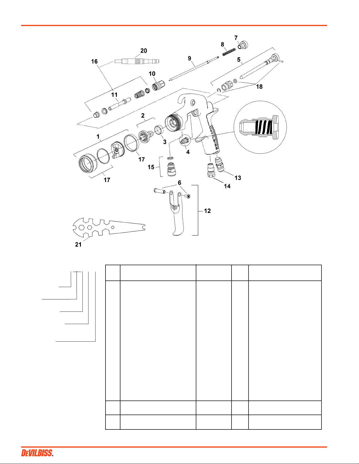
PARTS LIST
Ref.
No. Description Part Number Qty. Options
1 Air Cap/Retaining ring SP-100-***-K 1 506, 507, 508 e.g *** = 506
COM-506, COM-507, or COM-508
2 Nozzle SP-200S-**-K 1
+3 Separator (Pack of 5) SP-623-K5 1
+4 Packing (Pack of 2) GTI-445-K2 1
5 Spreader Valve SP-401-K 1
6 Stud and Screw 1
7 Needle Adjusting Screw SP-614-K 1
+8 Spring (Pack of 5) SP-622-K5 1
9 Needle SP-300S-**-K 1
10 Airvalve housing & seal SP-612-K 1
•11 Spindle 1
12 Trigger, Stud and Screw SP-617-CR-K 1
13 Connector SP-611-K 1
14 Plug JGA-132 1
15 Fluid Inlet Connector and seal SP-636-K 1
17 Retaining Ring and Seals SPK-102-K 1
+18 Clip, Seal and Pin Kit (Pack of 5) GTI-428-K5 1
• 20 Air Valve Assembly Tool 1
21 Spanner SPN-5 1
Spraygun Service Kit includes SPK-402-K 1
1 each of parts marked +
16 Air Valve Service Kit includes SPK-101-K 1
1 each of parts marked •
085, 10, 12, 14, 16, 18, 22 e.g ** =14 =1.4 mm
085, 10, 12, 14, 16, 18, 22 e.g ** =14 =1.4 mm
*T-20 six point star wrench required.
SB-2-545-L (5/2016)4 / 12
Page 5
EN
SPECIFICATION
Air supply connection:
Universal 1/4" BSP and NPS
Fluid supply connection:
Universal 3/8" BSP and NPS
Maximum static Air inlet pressure:
P1 = 12 bar (175 psi)
Maximum static Fluid inlet pressure:
P2 = 15 bar (218 psi)
Nominal gun Air inlet pressure
with gun triggered:
1.5 bar (22 psi) 507 HVLP Air Cap
1.1 bar (16 psi) 506 HVLP Air Cap
Maximum Service temperature:
40°C / 104°F
Gun Weight: 412 g / 14.5 oz.
MATERIALS OF CONSTRUCTION
Gun body: Anodized Aluminum
Nozzle: Stainless Steel
Needle: Stainless Steel
Fluid Inlet / Fluid Passages:
Stainless Steel / PTFE
Trigger: Nickel Plated Steel
AIR CAP SPECIFICATIONS
SP-100-506-K (Pressure Feed)
12.2 CFM @ 16 psi inlet
Fan Pattern Max: 11.8"
SP-100-507-K (Pressure/Siphon)
17.3 CFM @ 22 psi inlet
Fan Pattern Max: 15.7"
SP-100-508-K (Pressure Feed)
11.0 CFM @ 14 psi inlet
Fan Pattern Max: 10"
INSTALLATION
Important: To ensure that this
equipment reaches you in first
class condition, protective
coatings have been used. Flush
the equipment through with a
suitable solvent before use.
1. Attach air hose to connector (13).
Recommended hose size 8 mm
bore. The hose must be conductive
and electrical bond from the
spraygun to earth should be checked
with an ohmeter. A resistance of less
than 106 Ohms is recommended.
2. Attach fluid supply hose to Fluid
Inlet (15).
OPERATION
1. Mix coating material to
manufacturers instructions
2. Turn needle adjusting screw (7)
clockwise to prevent movement.
3. Turn spreader valve (5) counterclockwise to fully open.
4. Adjust inlet air pressure (For
recommended figures see
Specifications) at the gun inlet with
the gun triggered. (pressure gauge
attachment shown under
Accessories is recommended for
this).
5. Turn needle adjusting screw counter
clockwise until first thread shows.
6. Test spray. If the finish is too dry
reduce airflow by reducing air inlet
pressure or by the Airflow Valve (14).
Screw the Adjusting Knob (14) in to
reduce pressure.
7. If finish is too wet reduce fluid flow
by turning needle screw (7) clockwise
or reducing the fluid pressure. If
atomization is too coarse, increase
inlet air pressure. If too fine reduce
inlet pressure.
8. The pattern size can be reduced by
turning spreader valve (5) clockwise.
9. Hold gun perpendicular to surface
being sprayed. Arcing or tilting may
result in uneven coating.
10. The recommended spray distance is
150-200 mm (6"-8").
11. Spray edges first. Overlap each
stroke a minimum of 50%. Move gun
at a constant speed.
12. Always turn off air and fluid supply
and relieve pressure when gun is
not in use.
PREVENTATIVE MAINTENANCE
1. Turn off air and coating supply and
relieve pressure in the supply lines,
or if using QD system, disconnect
from airline and fluid line.
2. Remove air cap (1) and clean. If any
of the holes in the cap are blocked
with coating material use a toothpick
to clean. Never use metal wire which
could damage the cap and produce
distorted spray patterns
3. Ensure the tip of the nozzle (2) is
clean and free from damage. Build
up of dried paint can distort the
spray pattern.
4. Lubrication – stud/screw (6), packing
(4) and air valve (11) should be oiled
each day.
REPLACEMENT OF PARTS
Nozzle (2) and Needle (9) – Remove parts
in the following order: 7, 8, 9, 1 and 2.
Replace any worn or damaged parts and
re-assemble in reverse order.
Recommended tightening torque for
nozzle (2) 9.5-12 Nm (80-100 lbf in).
Packing – Remove parts 7, 8, 9. Unscrew
cartridge (4). Fit new cartridge finger
tight. Re-assemble parts 9, 8, and 7 and
tighten cartridge (4) with spanner
sufficient to seal but to allow free
movement of needle. Lubricate with gun
oil.
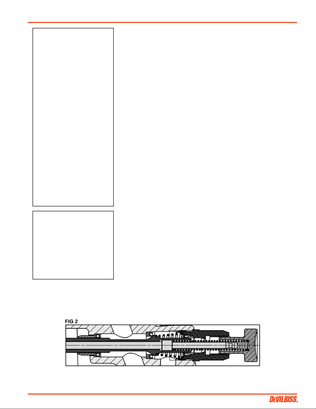
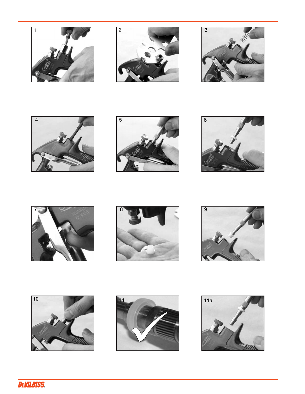
Air Valve Seal Kit (16) – (Refer to photos
1 to 28 and fig 2)
Spreader valve (5) – Caution: always
ensure that the valve is in the fully open
position by turning screw fully counterclockwise before fitting to body.
SB-2-545-L (5/2016) 5 / 12
Page 6
EN
1. Remove Adjusting Knob (7),
Spring (8), and Needle (9).
4. Remove Spindle (11). 5. Using Service Tool SPN-7,
2. Loosen Housing (10). 3. Remove Housing (10) and
engage groove behind the
Valve Seat.
Airvalve Spring.
6. Remove Valve Seat.
7. Push out the Front Airvalve
Seal with a finger.
10. Fit new Seal to gunbody and
press firmly to ensure Seal is
engaged.
8. Turn the Gun upside down
and let the Seal fall out.
11. Fit New Valve Seat to Service
Tool. Groove must face
outwards.
9. Fit New Front Seal to Service
Tool.
SB-2-545-L (5/2016)6 / 12
Page 7
EN
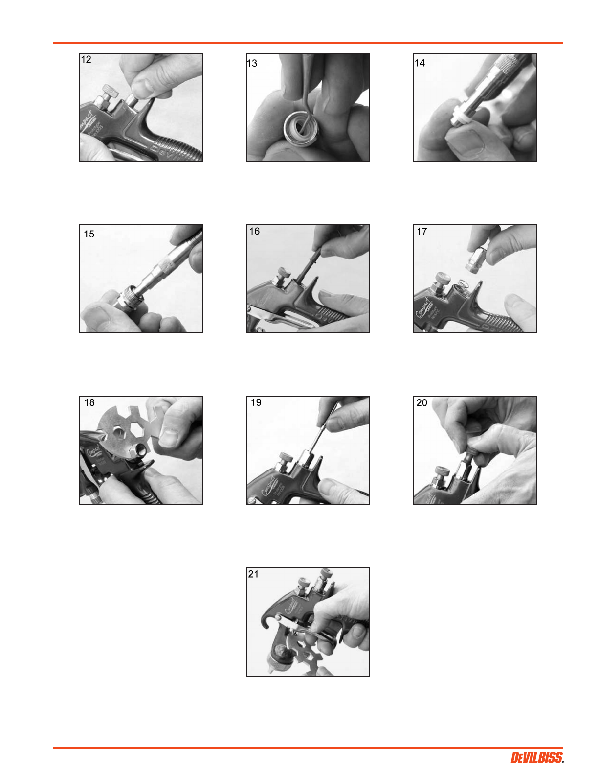
12. Fit Valve Seat to Gunbody. 13. Remove Rear Airvalve Seal
from housing (10) with a
hooked instrument.
15. Fit Seal to Housing (10). 16. Replace Spindle (11). 17. Replace Valve Spring and
14. Fit new Seal to Service Tool.
attach Housing (10).
18. Tighten Housing. 19. Fit Needle (9). 20. Fit Spring (8) and Knob (7).
21. Adjust Needle Packing (4)
with Spanner sufficient to
seal but to allow free
movement of needle.
Lubricate with gun oil.
SB-2-545-L (5/2016) 7 / 12
Page 8
EN
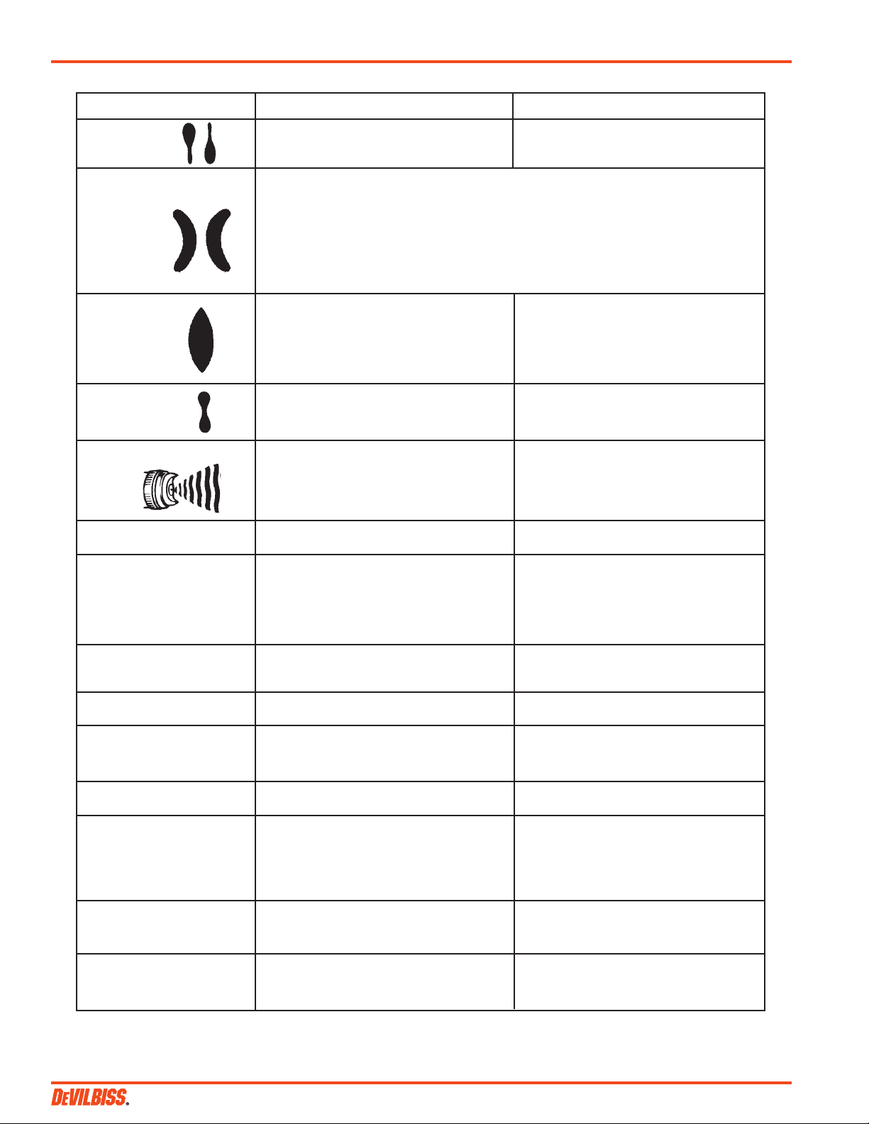
TROUBLESHOOTING
CONDITION CAUSE CORRECTION
Heavy top or Horn holes plugged. Clean. Ream with non-metallic point.
bottom pattern Obstruction on top or bottom of fluid tip. Clean.
Cap and/or tip seat dirty. Clean.
Heavy right or left side pattern Left or right side horn holes plugged. Clean. Ream with non-metallic point.
Dirt on left or right side of fluid tip. Clean.
Remedies for the top-heavy, bottom-heavy, right-heavy and left-heavy patterns:
1) Determine if the obstruction is on the air cap or the fluid tip. Do this by making a test spray
pattern. Then, rotate the cap one-half turn and spray another pattern. If the defect is inverted,
obstruction is on the air cap. Clean the air cap as previously instructed.
2) If the defect is not inverted, it is on the fluid tip. Check for a fine burr on the edge of the fluid tip.
Remove with #600 wet or dry sand paper.
3) Check for dried paint just inside the opening. Remove paint by washing with solvent.
Heavy center pattern Fluid pressure too high for atomization Balance air and fluid pressure.
air (pressure feed). Increase spray pattern width with
spreader adjustment valve.
Material flow exceeds air cap's capacity. Thin or lower fluid flow.
Spreader adjustment valve set too low. Adjust.
Atomizing pressure too low. Increase pressure.
Material too thick. Thin to proper consistency.
Split spray pattern Atomization air pressure too high. Reduce at transformer or gun.
Fluid pressure too low (pressure feed only). Increase fluid pressure (increases gun
handling speed).
Spreader adjusting valve set too high. Adjust.
Jerky or fluttering spray *Loose or damaged fluid tip/seat. Tighten or replace.
Material level too low. Refill.
Container tipped too far. Hold more upright.
Obstruction in fluid passage. Backflush with solvent.
Loose or broken fluid tube or fluid inlet nipple. Tighten or replace.
Dry or loose fluid needle packing nut. Lubricate or tighten.
Unable to get round spray Spreader adjustment screw not seating properly. Clean or replace.
Air cap retaining ring loose. Tighten.
Will not spray No air pressure at gun. Check air supply and air lines.
Internal mix or pressure feed air cap and tip Change to proper suction feed air cap and tip.
used with suction feed.
Fluid pressure too low with internal mix cap and Increase fluid pressure at tank.
pressure tank.
Fluid needle adjusting screw not open enough. Open fluid needle adjusting screw.
Fluid too heavy for suction feed. Thin material or change to pressure feed.
Excessive overspray Too much atomization air pressure Reduce pressure.
Gun too far from work surface. Adjust to proper distance.
Improper stroking (arcing, gun motion too fast). Move at moderate pace, parallel towork surface.
Excessive fog Too much, or too fast-drying thinner. Remix properly.
Too much atomization air pressure. Reduce pressure.
Dry Spray Air pressure too high. Reduce air pressure.
Gun tip too far from work surface. Adjust to proper distance.
Gun motion too fast. Slow down.
Gun out of adjustment Adjust.
Fluid leaking from packing nut Packing nut loose. Tighten, do not bind needle.
Packing worn or dry Replace or lubricate.
Fluid leaking or dripping from Packing nut too tight. Adjust.
front of pressure feed gun Dry packing. Lubricate.
Fluid tip or needle worn or damaged. Replace tip & needle with lapped sets.
Foreign matter in tip. Clean.
Fluid needle spring broken. Replace.
Wrong size needle or tip. Replace.
Runs and sags Too much material flow. Adjust gun or reduce fluid pressure.
Material too thin. Mix properly or apply light coats.
Gun tilted on an angle, or gun motion too slow. Hold gun at right angle to work and adapt to
proper gun technique
Thin, sandy coarse finish Gun too far from surface. Check distance. Normally approx. 8".
drying before it flows out
Too much air pressure. Reduce air pressure and check spray pattern.
Improper thinner being used. Follow paint manufacturer's mixing instructions.
*Most common problem.
SB-2-545-L (5/2016)8 / 12
Page 9

TROUBLESHOOTING (continued)
CONDITION CAUSE CORRECTION
Thick, dimpled finish "orange Gun too close to surface. Check distance. Normally approx. 8".
peel". Too much material coarsely atomized. Increase air pressure or decrease fluid pressure.
Air pressure too low. Increase air pressure or reduce fluid pressure.
Improper thinner being used. Follow paint manufacturer's mixing instructions.
Material not properly mixed. Follow paint manufacturer's mixing instructions.
Surface rough, oily, dirty. Properly clean and prepare.
EN
SB-2-545-L (5/2016) 9 / 12
Page 10

EN
ACCESSORIES
P-H-5516 Air
Adjusting Valve
HAV-500 or
HAV-501
Adjusting Valve
(HAV-501 SHOWN)
HD-503
SolventSaver™
Hose/Gun Cleaner
HARG-510 Air
Regulator
29-3100 Scrubs®
Hand Cleaner
Towels
SPN-5
Wrench
Enables user to control
and reduce air usage
at the gun. Ideal for
low pressure spraying.
42884-214-K5 3/8"
42884-215-K10 5/8"
Cleaning Brushes
These brushes are
helpful in cleaning
threads and recesses
of gun body.
Millennium 3000
Twin Cartridge Paint Spray Respirator
HAV-500 does not have
pressure gage. Use to
control air usage at
gun.
PLH-MF-6-100
Mini-Strainer
(100 mesh)
For trapping foreign
particles in the paint
supply.
40-141 Small
40-128 Medium
40-143 Large
NIOSH-Certified, for respiratory protection in
atmospheres not immediately dangerous to life.
TLC-576 Aluminum Cup
(Non-stick Lined) &
TSC-591Stainless Steel Cup
1 Qt. pressure feed cups.
3/8" NPS (F), cam lock lid.
Requires KK-4980 air
regulator kit.
83C-220
2 Gallon Tank
80-600
SG2 Plus Cup
2 Qt Hose/Gun Cleaner
used to clean the
inside of hose, fluid
passageways of gun &
other paint equipment.
183GZ-5200
SolventSaver™
Use to maintain nearly
constant outlet pressure
despite changes in
inlet pressure and
downstream flow.
SP-402-K Air
Adjusting Valve
Hose/Gun Cleaner
2 Gallon galvanized
tank used to clean the
inside of hose and
material passages of
the gun.
Quick Disconnect Approved for
HVLP Guns (Air)
High Flow Ball and Ring Type
HC-4419 1/4"
NPS(F)
HC-4720
1/4" NPT(F)
Installs into gun to
enable user to control
and reduce air usage
at the gun. Replaces
SP-637 plug.
HC-4719
1/4" NPT(M)
HC-1166
1/4" NPT(M)
MPV-60-K3
Air Inlet Swivel
(Pack of 3)
Fits Compact gun only.
Compatible with DeVilbiss high
flow quick disconnects.
80-295 Cup
Air Cap Test Kits
Scrubs® are a
pre-moistened hand
cleaner towel for
painters. No water is
needed.
Compatible with all
paint materials:
contains no silicone or
petroleum distillates to
contaminate paint.
MSDS sheet available
upon request.
KB-555 (Aluminum) &
KB-545-SS (S/S) 2 qt. Pressure
Feed Cup With Regulator
Provides greater
degree of control
over cup fluid
pressure.
Compatible with SP-200S-08-K (0.55 mm) and
KK-5090-506
KK-5090-507
KK-5090-508
Contains all necessary
tip, hose and nut sizes
used on or with gun.
Spray Gun Lube
SSL-10 (2 oz.
bottle)
TGC-545 Aluminum
TLC-555 Non-stick Lined
TGC-595 Stainless Steel
Siphon Cups
HAF-507
Whirlwind™
In-Line Air Filter
Removes water, oil,
and debris from the air
line.
Plastic Tipped Fluid Needle
SP-300P-10-K
SP-200S-10-K (1.0 mm) fluid tips
SP-300P-14-K
Compatible with SP-200S-14-K fluid tips
Zinc plated tank. 2 qt. cup.
Waterborne
compatible when
80-356 liner is used.
2 qt. aluminum cup
with regulator.
The purpose of this test
kit is to measure air cap
atomizing air pressure at
the center air port of the air
cap. Used to confirm code
compliance and as a daily
quality control measure.
SB-2-545-L (5/2016)10 / 12
Page 11

NOTES
EN
SB-2-545-L (5/2016) 11 / 12
Page 12

EN
WARRANTY POLICY
DeVilbiss products are covered by Carlisle Fluid Technologies one year materials and workmanship limited warranty.
The use of any parts or accessories, from a source other than Carlisle Fluid Technologies, will void all warranties.
For specic warranty information please contact the closest Carlisle Fluid Technologies location listed below.
Carlisle Fluid Technologies reserves the right to modify equipment specications without prior notice.
DeVilbiss®, Ransburg®, MS®, BGK®, and Binks® are registered trademarks of Carlisle Fluid Technologies, Inc.
©2016 Carlisle Fluid Technologies, Inc. All rights reserved.
DeVilbiss is part of Carlisle Fluid Technologies, a global leader in innovative nishing
technologies. For technical assistance or to locate an authorized distributor,
contact one of our international sales and customer support locations.
USA/Canada
info@carlisleft.com
Tel: 1-888-992-4657
Fax: 1-888-246-5732
United Kingdom
info@carlisleft.eu
Tel: +44 (0)1202 571 111
Fax: +44 (0)1202 573 488
China
mkt@carlisleft.com.cn
Tel: +8621-3373 0108
Fax: +8621-3373 0308
For the latest information about our products, visit www.carlisleft.com.
Mexico
ventas@carlisleft.com.mx
Tel: 011 52 55 5321 2300
Fax: 011 52 55 5310 4790
France
info@carlisleft.eu
Tel: +33(0)475 75 27 00
Fax: +33(0)475 75 27 59
Japan
overseas-sales@carlisleft.co.jp
Tel: 081 45 785 6421
Fax: 081 45 785 6517
Brazil
vendas@carlisleft.com.br
Tel: +55 11 5641 2776
Fax: 55 11 5641 1256
Germany
info@carlisleft.eu
Tel: +49 (0) 6074 403 1
Fax: +49 (0) 6074 403 281
Australia
sales@carlisleft.com.au
Tel: +61 (0) 2 8525 7555
Fax: +61 (0) 2 8525 7575
SB-2-545-L (5/2016)12 / 12
Page 13

MANUAL DE SERVICIO
MANUAL DE OPERACIÓN
COMPACT – PISTOLA PULVERIZADORA
POR PRESIÓN / POR SIFÓN HVLP
ES
SB-2-545-L (5/2016) ES-1 / 12
Page 14

ES
Descripción del producto / Objeto de la
Adecuado para su uso en áreas peligrosas:
Este Producto está diseñado para su uso
El objeto de la declaración descrita anteriormente es conforme con la legislación de armonización de la
Esta declaración de conformidad /
Finishing Brands UK Ltd,
Nivel de protección:
II 2 G X
Notificado de carrocería y papel :
Element Materials Technology. WN8 9PN UK
Presentación de Ficha técnica
11-May-16
Proporcionar todas las condiciones de uso seguro / instalación indicado en los manuales de los productos se han cumplido y
(Gerente general)
Compact Series Spray Guns
Declaración :
Materiales de base de agua y disolventes
con:
Zona 1 / Zona 2
incorporación se expide bajo la exclusiva
responsiblility del fabricante:
Ringwood Road,
Bournemouth, BH11 9LH. UK
Declaración de conformidad EU
Unión pertinente :
Directiva de máquinas 2006/42/CE
Directiva ATEX 2014/34/EU
ya que es conforme con las siguientes normas armonizadas y documentos estatutarios :
EN ISO 12100:2010 Seguridad de las máquinas - Principios generales para el diseño
EN 13463-1:2009 Equipos no eléctricos destinados a atmósferas potencialmente explosivas - Requisitos y metodología básica
El objeto de la declaración descrita anteriormente es conforme con la legislación de armonización d
94/9/CE ( hasta abril 19 de , 2016) , y la Directiva 2014/34/UE ( del 20 de abril , 2016)
e la Unión pertinente : Directiva
también se instala de acuerdo con todos los códigos locales aplicables de la práctica .
Firmado para y en representacion de
Finishing Brands UK Ltd :
Dave Smith
Bournemouth,BH11 9LH,UK
4-3197R-1
SB-2-545-L (5/2016)ES-2 / 12
Page 15

IMPORTANTE: Lea y siga todas las
instrucciones y Precauciones de Seguridad
antes de utilizar este equipo.
DESCRIPCIÓN
El Kit de Pistola Pulverizadora por Presión
Compact cumple las normas ATEX 94/9/
CE, nivel de protección; II 2 G X, Adecuado
para el uso en las Zonas 1 y 2.
IMPORTANTE: Estas Pistolas
pulverizadoras son apropiadas para el
uso con materiales de recubrimiento a
base de agua o de disolventes. El diseño
utiliza tecnología de pulverización HVLP
para reducir la sobrepulverización y
mejorar la eficacia del recubrimiento. Si
tiene alguna duda respecto a la idoneidad
de un material específico, póngase en
contacto con su Distribuidor local o
directamente con DeVilbiss.
DeVilbiss se reserva el derecho a modificar las especificaciones del equipo sin
previo aviso.
PROP
65
DE CA
ADVERTENCIA PROP 65
ADVERTENCIA: Este producto contiene
sustancias químicas que según información en
poder del estado de California producen
cáncer, defectos de nacimiento y otros daños al
sistema reproductor.
ES
ADVERTENCIAS DE SEGURIDAD
INCENDIO Y EXPLOSIÓN
Los disolventes y los materiales de recubrimiento pueden ser altamente
inflamables o combustibles al pulverizarse. Consulte SIEMPRE las instrucciones
del fabricante del material de recubrimiento y las hojas MSDS antes de utilizar
este equipo.
Los usuarios deben cumplir la normativa nacional y local y los requisitos de las
compañías de seguros respecto a ventilación, precauciones contraincendios,
operación y mantenimiento de las zonas de trabajo.
Este equipo, tal y como se suministra, NO es adecuado para su uso con
Hidrocarburos Halogenados.
La Electricidad Estática puede ser generada por el paso de fluido y/o aire por los
manguitos, por el proceso de pulverización y por la limpieza de piezas no
conductoras con paños. Para impedir que las descargas estáticas produzcan
fuentes de ignición, debe mantenerse la continuidad de tierra a la pistola
pulverizadora y a otros equipos metálicos utilizados.
EQUIPO DE PROTECCIÓN PERSONAL
Vapores tóxicos - Al pulverizarse, ciertos materiales pueden ser tóxicos, crear
irritación o ser dañinos para la salud de otra forma. Lea siempre todas las
etiquetas y hojas de datos de seguridad del material antes de pulverizar, y siga
cualquier recomendación. En caso de Duda, Póngase en Contacto con el
Proveedor del Material.
Se recomienda el uso de equipos de protección respiratoria en todo momento. El
tipo de equipo debe ser compatible con el material que se está pulverizando.
Lleve siempre protección ocular al pulverizar o al limpiar la pistola.
Deben llevarse guantes al pulverizar o al limpiar la pistola.
Formación - El personal debe recibir una formación adecuada en el uso seguro
de equipos de pulverización.
MAL USO
No apunte nunca con una pistola de pulverización a ninguna parte del cuerpo.
No supere nunca la presión máxima de operación segura recomendada del
equipo.
El acoplamiento de piezas de repuesto no recomendadas o no originales puede
crear riesgos.
Antes de realizar limpieza o mantenimiento, toda presión debe aislarse y aliviarse
en el equipo.
El producto debe ser limpiado usando una máquina para lavar pistolas. No
obstante, este equipo no debe dejarse dentro de una máquina de lavar pistolas
durante periodos de tiempo prolongados.
NIVELES SONOROS
El nivel sonoro con ponderación A de las pistolas de pulverización puede superar
los 85 dB(A) dependiendo de la configuración utilizada. Los detalles de niveles
sonoros reales están disponbles previa petición. Se recomienda llevar protección
acústica en todo momento durante la pulverización.
OPERACIÓN
Los Equipos de Pulverización que funcionan a alta presión pueden verse
sometidos a fuerzas de retroceso. Bajo determinadas circunstancias, dichas
fuerzas podrían provocar al operador lesiones por esfuerzo repetitivo (RSI).
SB-2-545-L (5/2016) ES-3 / 12
Page 16

ES
Patente Nº 2372465 (GB)
MODELO-NÚMERO PIEZA
Ejemplo: COM-PS506B-14-00
Conducto de
fluido en acero
inoxidable
Casquillo de aire
Azul anodizado
Diámetro del pico
de fluido
(14 = 1.4 mm)
00 = Sin taza
01 = Taza de sifón
LISTA DE PIEZAS
Nº Número
Ref. Descriptión de Pieza Cant Opciones
1
2 Pico de fluido SP-200S-**-K 1
+3 Separador (
+4 Empaquetadura (
5 Válvula dispersora SP-401-K 1
6 Espiga y tornillo 1
7 Tornillo de ajuste de la aguja SP-614-K 1
+8 Muelle (
9 Aguja SP-300S-**-K 1
10 Alojamiento de la válvula de aire SP-612-K 1
•11 Vástago 1
12 Gatillo, espiga y tornillo SP-617-CR-K 1
13 Conector SP-611-K 1
14 Tapón JGA-132 1
15 Entrada de fluido – Conector y junta SP-636-K 1
17 Retén y juntas SPK-102-K 1
+18 Kit de clip, junta y perno (
• 20 Herramienta para el conjunto de
21 Llave SPN-5 1
Kit de Mantenimiento de la SPK-402-K 1
16 Kit de mantenimiento de la SPK-101-K 1
Casquillo de aire / Anillo de retención
COM-506, COM-507, o COM-508
paquete
de 5) SP-623-K5 1
paquete
paquete
de 5) SP-622-K5 1
& junta
la válvula de aire 1
Pistola Pulverizadora, incluye: 1 por cada uno de las piezas marcadas con +
válvula de aire, incluye: 1 por cada uno de las piezas marcadas con •
SP-100-***-K 1 506, 507, 508 ej. *** = 506
085, 10, 12, 14, 16, 18, 22 ej. ** =14 =1.4 mm
de 2) GTI-445-K2 1
085, 10, 12, 14, 16, 18, 22 ej. ** =14 =1.4 mm
paq.
de 5) GTI-428-K5 1
* T-20 de seis puntos llave de estrella necesario.
SB-2-545-L (5/2016)ES-4 / 12
Page 17

ES
ESPECIFICACIÓN
Conexión del suministro de aire:
Universal 1/4" BSP y NPS
Conexión del suministro de fluido:
Universal 3/8" BSP y NPS
Presión estática máxima de entrada
de aire: P1 = 12 bar (175 psi)
Presión estática máxima de entrada
de fluido: P2 = 15 bar (218 psi)
Presión nominal de entrada de aire
en la pistola – con el gatillo apretado:
1.5 bar (22 psi) casquillo de aire 507 HVLP
1.1 bar (16 psi) casquillo de aire 506 HVLP
Temperatura Máxima de uso:
40°C / 104°F
Peso de pistola: 412 g / 14.5 oz.
MATERIALES DE CONSTRUCCIÓN
Cuerpo de la pistola: Aluminio
anodizado
Boquilla: Acero inoxidable
Aguja: Acero inoxidable
Entrada de fluido / Conductos de fluido:
Acero inoxidable / PTFE
Gatillo: Acero niquelado
INSTALACIÓN
Importante: Para asegurarse
de que este equipo llega a
usted en condiciones óptimas,
se han utilizado recubrimientos
protect ores. Enjuague el equipo
con un disolvente adecuado
antes de su uso.
1. Acople el manguito de aire al
conector (13). Tamaño de manguito
recomendado: 8 mm diám. interior.
El manguito debe ser conductor de
electricidad y la conexión eléctrica
entre la pistola pulverizadora y tierra
debe verificarse con un ohmímetro.
Se recomienda una resistencia de
menos de 106Ω. El suministro de
aire debe estar filtrado y regulado.
2. Acople el manguito de suministro de
fluido a la Entrada de Fluido (15).
ESPECIFICACIÓNES DE
CASQUILLO DE AIRE
SP-100-506-K (por presión)
12.2 CFM @ 16 psi entrada,
el tamaño del patrón máximo: 11.8"
SP-100-507-K (por presión/por sifón)
17.3 CFM @ 22 psi entrada,
el tamaño del patrón máximo: 15.7"
SP-100-508-K (por presión)
11.0 CFM @ 14 psi entrada
el tamaño del patrón máximo: 10"
OPERACIÓN
1. Mezcle el material de recubrimiento
siguiendo las instrucciones del
fabricante.
2. Gire el tornillo de ajuste de la aguja
(7) en el sentido de las agujas del
reloj para impedir que se mueva.
3. Gire la válvula de dispersión (5) en el
sentido contrario a las agujas del
reloj hasta que esté abierta del todo.
4. Ajuste la presión de aire de entrada
(ver valores recomendados en las
Especificaciones) en la entrada de
la pistola con el gatillo apretado.
(se recomienda utilizar para ello el
manómetro mostrado en
Accesorios).
5. Gire el tornillo de ajuste de la aguja
en el sentido contrario a las agujas
del reloj hasta que se vea la primera
rosca.
6. Haga una prueba de pulverización.
Si el acabado es demasiado seco,
reduzca el caudal de aire reduciendo
la presión de entrada de aire o
mediante la Válvula de Caudal de
Aire (14). Gire el Pomo de Ajuste (14)
hacia dentro para reducir la presión.
7. Si el acabado es demasiado húmedo,
reduzca el caudal de fluido girando
el tornillo de la aguja (7) en el
sentido de las agujas del reloj o
reduciendo la presión del fluido.
Si la atomización es demasiado
gruesa, aumente la presión de
entrada de aire. Si es demasiado
fina, reduzca la presión de entrada.
8. El tamaño del patrón puede
reducirse ajustando la válvula
dispersora (5) en el sentido de las
agujas del reloj.
9. Sujete la pistola perpendicular a la
superficie a pulverizar. Pulverizar en
arcos o con la pistola inclinada
puede producir un recubrimiento
desigual.
10. La distancia de pulverización
recomendada es de 150 - 200 mm.
11. Pulverice primero los bordes. Solape
cada pasada el 50% como mínimo.
Mueva la pistola a una velocidad
constante.
12. Cierre siempre el suministro de aire
y fluido y alivie la presión cuando la
pistola no se esté utilizando.
MANTENIMIENTO PREVENTIVO
1. Cierre el suministro de aire y
recubrimiento, y alivie la presión en
los manguitos, o si utiliza el sistema
QD, desconéctelo del manguito de
aire y de fluido.
2. Retire el casquillo de aire (1) y
límpielo. Si alguno de los orificios
del casquillo está obstruido con
material de recubrimiento, utilice un
palillo para limpiarlo. No utilice
nunca un alambre metálico, porque
podría dañar el casquillo y producir
patrones de pulverización
distorsionados.
3. Asegúrese de que la punta de la
boquilla (2) está limpia y libre de
desperfectos. Una acumulación de
pintura seca puede distorsionar el
patrón de pulverización.
4. Lubricación – la espiga/tornillo (6), la
empaquetadura (4) y la válvula de
aire (11) deben lubricarse con aceite
cada día.
SUSTITUCIÓN DE PIEZAS
Boquilla (2) y Aguja (9) – Retire las piezas
en el siguiente orden: 7, 8, 9, 1 y 2.
Sustituya cualquier pieza desgastada o
dañada y vuelva a montar las piezas en
orden inverso. Par de apriete
recomendado para la boquilla (2) 9,5-12
Nm (80-100 pies-libra/pulgada).
Guarnición – Retire las piezas 7, 8, 9.
Desenrosque el cartucho (4). Coloque un
cartucho nuevo y apriete con los dedos
solamente. Vuelva a montar las piezas 9,
8 y 7 y apriete el cartucho (4) con una
llave, lo suficiente para hacer sello pero
dejando que la aguja se desplace
libremente. Lubrique con aceite para
pistolas.
Kit de Junta de la Válvula de Aire (16) –
(Ver FIG 2 y fotos 1 a 28).
Válvula Dispersora (5) – Precaución:
asegúrese siempre de que la válvula está
en posición completamente abierta
girando el tornillo en el sentido contrario
a las agujas del reloj hasta que haga tope
antes de instalarla en el cuerpo de la
pistola.
SB-2-545-L (5/2016) ES-5 / 12
Page 18

ES
1. Retire el pomo de ajuste (7),
el muelle (8), y la aguja (9).
4. Retire la vástago (11). 5. Usando la herramienta de
2. Afloje el alojamiento (10). 3. Retire el alojamiento (10) y
manteni-miento SPN-7,
enganche la muesca detrás
del asiento de la válvula.
el muelle de la válvula de
aire.
6. Retire el asiento de la
válvula.
7. Haga salir la junta delantera
de la válvula de aire
empujando con el dedo.
10. Coloque la junta nueva sobre
el cuerpo de la pistola y empuje
firmemente para asegurarse
de que la junta quede
correctamente colocada.
8. Ponga la pistola boca abajo
y deje que se caiga la junta.
11. Coloque un asiento de
válvula nuevo en la
herramienta de
mantenimiento.
9. Instale una junta delantera
nueva en la herramienta de
mantenimiento.
SB-2-545-L (5/2016)ES-6 / 12
Page 19

ES
12. Coloque el asiento de
válvula en el cuerpo de la
pistola.
15. Coloque la junta en el
alojamiento (10).
13. Retire la junta de la válvula
de aire del alojamiento (10)
con un instrumento que
tenga gancho.
16. Vuelva a colocar el vástago
(11).
14. Instale una junta nueva en la
herramienta de
mantenimiento.
17. Vuelva a colocar el muelle
de la válvula y vuelva a
colocar en el alojamiento
(10).
18. Apriete el alojamiento. 19. Coloque la aguja (9). 20. Instale el muelle (8) y el
21. Ajuste la guarnición de la aguja (4) con
una llave lo suficiente para hacer sello
pero permitiendo que se desplace la
aguja. Lubrique con aceite para pistolas.
pomo (7).
SB-2-545-L (5/2016) ES-7 / 12
Page 20

ES
LOCALIZACIÓN Y REPARACIÓN DE PROBLEMAS
CONDICIÓN CAUSE CORRECCIÓN
Patrón pesado en
la parte superior
o inferior
Agujeros de la horquilla obstruidos.
Obstrucción en la parte superior o inferior de la punta de fluido.
Casquillo y/o asiento de la punta está sucio.
Limpie. Escariar con punta no metálica.
Limpie.
Limpie.
Patrón pesado en el lado
derecho o izquierdo
Patrón pesado en
el centro
Patrón de
pulverización
dividida
Pulverización entrecortada o con
vibraciones
Imposibilidad de obtener pulverización
redondeada
No pulveriza
Sobrepulverización excesiva
Nebulización excesiva
Pulverización seca
Escape de fluido por la tuerca de la
empaquetadura
Escape o goteo de fluido por la parte
delantera de la pistola alimentada
por presión
Agujeros en el lado izquierdo o derecho de la horquilla obstruidos.
Suciedad en el lado izquierdo o derecho de la punta del líquido.
Corrección de los patrones pesados en la parte superior, inferior, el lado derecho e izquierdo.
1. Determine si la obstrucción está en el casquillo de aire o en la punta de fluido. Realice esto haciendo una prueba del patrón
de pulverización. Luego gire el casquillo media vuelta y pulverice con otro patrón. Si se invierte el defecto, la obstrucción se
encuentra en el casquillo de aire. Limpie el casquillo de aire siguiendo las instrucciones previas.
2. Si el defecto no se invierte, la obstrucción se encuentra en la punta de fluido. Verifique si hay una pequeña protuberancia en
el borde de la punta de fluido. Quítela con papel de lija #600 húmedo o seco.
3. Verifique si hay pintura seca dentro de la abertura; elimínela lavándola con disolvente.
La presión del fluido es demasiado alta para el aire de
atomización (alimentado por presión).
El flujo del material sobrepasa la capacidad del casquillo de aire.
El ajuste de la válvula dispersora es muy bajo.
La presión de atomización es muy baja.
El material es muy espeso.
La presión de aire de atomización es muy alta.
La presión del fluido es muy baja (únicamente alimentada por
presión).
El ajuste de la válvula dispersora es muy alto.
*La punta/el asiento del fluido está flojo o dañado.
El nivel del material es muy bajo.
El recipiente se inclinó mucho.
Obstrucción en el conducto del fluido.
El tubo del fluido o la boquilla de entrada del fluido está flojo o roto.
La tuerca de la empaquetadura de la aguja de fluido seca o floja.
El tornillo de ajuste del dispersador no está alojado debidamente.
El anillo de retención del casquillo de aire está flojo.
No hay presión de aire en la pistola.
La mezcla interna o el casquillo de aire alimentado por presión
y la punta utilizados con alimentación por succión.
La presión del fluido es muy baja con el casquillo de la mezcla
interna y el tanque de presión.
El tornillo de ajuste de la aguja de fluido no está lo suficientemente abierto.
El fluido es muy pesado para la alimentación por succión.
Demasiada presión de aire de atomización.
La pistola está muy alejada de la superficie de trabajo.
Carrera indebida (formación de arco, el desplazamiento de la pistola es muy rápido).
Demasiado diluyente o diluyente de secado muy rápido.
Demasiada presión de aire de atomización.
Presión de aire muy alta.
Punta de pistola muy alejada de superficie de trabajo.
El desplazamiento de la pistola es muy rápido.
Pistola desajustada.
Tuerca de la empaquetadura floja.
Empaquetadura gastada o seca.
Tuerca de la empaquetadura muy apretada.
Empaquetadura seca.
Punta de fluido o aguja gastada o dañada.
Materias foráneas en la punta.
Muelle de la aguja del fluido roto.
Aguja o punta de tamaño inadecuado.
Limpie. Escariar con punta no metálica.
Limpie.
Equilibre la presión de aire y flujo de fluido.
Au mente el ancho del patrón de pulverización con la válvula
de ajuste del dispersador.
Diluya o baje el flujo de fluido.
Ajuste.
Aumente la presión.
Diluya hasta lograr la consistencia adecuada.
Reduzca la presión en el transformador o en la pistola.
Au mente la presión del fluido (aumente la velocidad de
manipulación de la pistola).
Ajuste.
Apriete o reemplace.
Vuelva a llenar.
Sosténgalo de forma más vertical.
Limpie con disolvente.
Apriete o reemplace.
Lubrique o apriete.
Limpie o reemplace.
Apriete.
Verifique el suministro de aire y las líneas de aire.
Ca mbie el casquillo de aire y la punta a la alimentación por
succión adecuada.
Aumente la presión del fluido en el tanque.
Abra el tornillo de ajuste de la aguja de fluido.
Diluya el material o cambie a alimentación por presión.
Reduzca la presión.
Ajuste hasta la distancia debida.
Desplácese a ritmo moderado, paralelo a la superficie de trabajo.
Vuelva a mezclar adecuadamente.
Reduzca la presión.
Reduzca la presión de aire.
Ajuste hasta la distancia debida.
Desacelere.
Ajuste.
Apriete, no bloquee la aguja.
Reemplace o lubrique.
Ajuste.
Lubrique.
Reemplace la punta y la aguja con instrumentos solapados.
Limpie.
Reemplace.
Reemplace.
Se corre
Acabado rugoso arenoso, fino,
que se seca antes de fluir.
*Problemas más comunes
Demasiado flujo de material.
El material es muy delgado.
Pi stola inclinada en un ángulo o el desplazamiento de la
pistola es muy despacio.
La pistola está muy alejada de la superficie.
Demasiada presión de aire.
Se está utilizando un diluyente inadecuado.
Ajuste la pistola o reduzca la presión de fluido.
Mezcle debidamente o aplique capas livianas.
So stenga la pistola en un ángulo correcto para trabajar y
adáptela a una técnica debida.
Verifique la distancia. Normalmente, aprox. 8 pulg.
Reduzca la presión de aire y verifique el patrón de pulverización.
Siga las instrucciones de mezclado del fabricante de la pintura.
SB-2-545-L (5/2016)ES-8 / 12
Page 21

LOCALIZACIÓN Y REPARACIÓN DE PROBLEMAS (continuación)
CONDICIÓN CAUSE CORRECCIÓN
Acabado grueso, no uniforme, como
el de una “cáscara de naranja”.
Pistola muy cerca de la superficie.
Demasiado material áspero fue atomizado.
Presión de aire muy baja.
Se está empleando un diluyente inadecuado.
No se ha mezclado debidamente el material.
Superficie áspera, aceitosa o sucia.
Verifique la distancia. Normalmente, aprox. 8 pulg.
Aumente la presión de aire o disminuya la presión del fluido.
Aumente la presión de aire o reduzca la presión del fluido.
Siga las instrucciones de mezclado del fabricante de la pintura.
Siga las instrucciones de mezclado del fabricante de la pintura.
Limpie y prepare debidamente.
ES
SB-2-545-L (5/2016) ES-9 / 12
Page 22

ES
ACCESORIOS
P-H-5516 Válvula
reguladora de aire
HAV-500 o
HAV-501
Válvula reguladora
(HAV-501 MOSTRADA)
HD-503
SolventSaver™
Limpiador de
manguito/pistola
HARG-510
Regulador de aire
29-3100 Scrubs®
Toallas para
limpiarse las manos
SPN-5
Llave
Permite al usuario controlar y
reducir el uso del aire en la
pistola. Ideal para
pulverización con presión baja.
42884-214-K5 3/8 de pulg.
42884-215-K10 5/8 de pulg.
Cepillos de limpieza
Estos cepillos ayudan a
limpiar las roscas y los lugares
ocultos del cuerpo de la
pistola.
Respirador para pulverizador de pintura
Millennium 3000
con cartucho doble
HAV-500 no tiene manómetro.
Utilizada para controlar el uso
del aire en la pistola.
PLH-MF-6-100
Mini-colador
(malla 100)
Para atrapar partículas
foráneas en el
suministro de pintura.
40-141 Pequeñas
40-128 Medianas
40-143 Grandes
Certificado por NIOSH, para protección de la respiración en
atmósferas que no implican riesgo inmediato para la vida.
Cubeta de aluminio
TLC-576
revestimiento antiadherente)
(forrada con
y Cubeta de acero
inoxidable TSC-591
Cubetas alimentadas por presión de
1 cuarto de galón. 3/8 de pulg. NPS (F),
tapa con cerrojo de leva. Requiere del
kit del regulador de aire KK-4980.
83C-220
Tanque de 2 galones
80-600
Cubeta SG2 Plus
Limpiador de manguito/pistola de
2 cuartos de galón, utilizado para
limpiar el interior del manguito, los
conductos de fluido de la pistola y
otros equipos de pintura.
183GZ-5200
SolventSaver™
Limpiador de
manguito/pistola
Tanque galvanizado de 2 galones
utilizado para limpiar el interior
del manguito y los conductos de
materiales de la pistola.
Dispositivo de desconexión
rápida aprobado para
pistolas HVLP (aire)
Tipo de bola y anillo de alto flujo
HC-4419 de 1/4 de pulg.
NPS(F)
HC-4720
de 1/4 de pulg. NPT(F)
Utilizado para mantener una
presión de salida casi
constante a pesar de los
cambios en la presión de
entrada y el flujo descendente.
SP-402-K Válvula
reguladora de aire
Se instala en la pistola para
permitir al usuario controlar y
reducir el uso de aire en la
pistola. Reemplaza el tapón
SP-637.
HC-4719
1/4 de pulg.
NPT(M)
HC-1166
1/4 de pulg. NPT(M)
MPV-60-K3
Eslabón giratorio de
entrada de aire
(paquete de 3)
Para pistola Compact únicamente.
Compatible con el dispositivo de
desconexión rápida de alto
flujo DeVilbiss.
80-295 Cubeta
Las Scrubs® son toallas
prehumedecidas para
limpiarse las manos los
pintores. No se necesita agua.
Lubricante de
pistola pulverizadora
SSL-10-K12 (botella de 2 oz.)
Compatible con todos los
materiales de pintura; no contiene
destilados de silicona ni petróleo
que contaminen la pintura. Hoja de
Datos de Seguridad de los
Materiales (MSDS, por sus siglas en
inglés) disponible previa solicitud.
KB-555 (aluminio) y KB-545-SS
(S/S) Cubeta de 2 cuartos de
galón alimentada por presión
con regulador
Proporciona un mayor grado
de control sobre la presión
del fluido de la cubeta.
Aguja de fluido con punta plástica
SP-300P-10-K
Compatible con puntas de fluido
SP-200S-08-K (0.55 mm) y
SP-200S-10-K (1.0 mm)
SP-300P-14-K
Compatible con puntas de fluido
SP-200S-14-K
Contiene todos los tamaños
necesarios de punta, manguito y
tuerca utilizados en o con la
pistola.
Cubeta de succión
de aluminio
TGC-545 aluminio
TLC-555
forrada con
revestimiento antiadherente
TGC-595 de acero
inoxidable
HAF-507
Filtro de aire en
línea Whirlwind™
Elimina el agua, el aceite y la
basura de la línea de aire
Zincado tanque. 2 cuarto. A base de
agua, material
compatible cuando
se utiliza de forros
80-356.
2 cuarto. Cubeta de
aluminio con
regulador.
KK-5090-506
KK-5090-507
KK-5090-508
Casquillo de aire
kits de prueba
El propósito de este kit de
prueba es medir el cabezal
de aire de atomización de
presión de aire en el puerto
de aire central de la tapa
de aire. Se utiliza para
confirmar el cumplimiento
del código, y como medida
de control de calidad diario.
SB-2-545-L (5/2016)ES-10 / 12
Page 23

NOTAS
ES
SB-2-545-L (5/2016) ES-11 / 12
Page 24

ES
POLÍTICA DE GARANTÍAS
Los productos DeVilbiss están cubiertos por la garantía limitada de materiales y mano de obra por un año
de Carlisle Fluid Technologies. El uso de cualquier pieza o accesorio de una fuente que no sea Carlisle Fluid
Technologies, anulará todas las garantías. Para obtener información especíca sobre la garantía, favor ponerse
en contacto con el local de Carlisle Fluid Technologies más cercano a usted entre los listados a continuación.
Carlisle Fluid Technologies se reserva el derecho de modicar las especicaciones del equipo sin previo aviso.
DeVilbiss®, Ransburg®, MS®, BGK®, y Binks® son marcas registradas de Carlisle Fluid Technologies, Inc.
©2016 Carlisle Fluid Technologies, Inc. Reservados todos los derechos.
DeVilbiss es parte de Finishing Brands, un líder global en tecnologías de acabados
pulverizados innovadores. Para asistencia técnica o para localizar un distribuidor
autorizado, póngase en contacto con uno de nuestros centros internacionales de
ventas y apoyo al cliente listados a continuación.
EE.UU/Canadá
info@carlisleft.com
Teléfono: 1-888-992-4657
Fax: 1-888-246-5732
Reino Unido
info@carlisleft.eu
Teléfono: +44 (0)1202 571 111
Fax: +44 (0)1202 573 488
China
mkt@carlisleft.com.cn
Teléfono: +8621-3373 0108
Fax: +8621-3373 0308
Para obtener la última información sobre nuestros productos, visite www.carlisleft.com.
México
ventas@carlisleft.com.mx
Teléfono: 011 52 55 5321 2300
Fax: 011 52 55 5310 4790
Francia
info@carlisleft.eu
Teléfono: +33(0)475 75 27 00
Fax: +33(0)475 75 27 59
Japón
overseas-sales@carlisleft.co.jp
Teléfono: 081 45 785 6421
Fax: 081 45 785 6517
Brasil
vendas@carlisleft.com.br
Teléfono: +55 11 5641 2776
Fax: 55 11 5641 1256
Alemania
info@carlisleft.eu
Teléfono: +49 (0) 6074 403 1
Fax: +49 (0) 6074 403 281
Australia
sales@carlisleft.com.au
Teléfono: +61 (0) 2 8525 7555
Fax: +61 (0) 2 8525 7575
SB-2-545-L (5/2016)ES-12 / 12
 Loading...