

Page 1
DeVilbiss® PulseDose® ComPaCt ConserVing DeViCe
erViCe manual
s
CAUTION-Federal (U.S.A.) law restricts this device to sale by or on the order of a physician.
Model PD1000
Page 2

GENERAL INFORMATION / THEORY OF OPERATION
TABLE OF CONTENTS
I. GENERAL INFORMATION
A. Initial Inspection ................................................................... 2
B. Maintaining the PD1000............................................................. 2
C. General Description ................................................................ 2
II. THEORY OF OPERATION ............................................................. 2
III. INSTALLATION AND OPERATION
A. Installation ....................................................................... 3
B. Operation ........................................................................ 3
IV. MAINTENANCE PROCEDURES
A. Testing .......................................................................... 4
B. Cleaning......................................................................... 4
V. TROUBLESHOOTING................................................................. 5
VI. SERVICE INSTRUCTIONS
A. Regulator Seal Replacement......................................................... 6
B. Battery Replacement ............................................................... 6
C. Cover / Regulator and Gauge Removal ................................................ 6
D. Cannula Fitting Removal/Replacement ................................................. 7
E. Solenoid/Vacuum Switch Testing and Removal........................................... 7
VII. PARTS AND IllUSTRATIONS ........................................................... 8
VIII. PNEUMATIC DIAGRAM ............................................................... 9
IX. UNIT SPECIFICATIONS ............................................................... 9
X. PROVIDER'S NOTES ................................................................. 9
XI. DEVILBISS GUIDANCE AND MANUFACTURER’S DECLARATION ............................ 10
XII. PARTS RETURN AND ORDERING POLICY ............................................... 11
XIII. WARRANTY ........................................................................ 11
I. GENERAL INFORMATION
A. Initial Inspection
An initial inspection should be performed on the PD1000 as soon as possible after receipt. When removed from
carton, an inspection should be made for any damage due to shipping. If shipping damage has occurred, call
DeVilbiss Healthcare at 800-338-1988 (814-443-4881) for replacement instructions.
B. Maintaining the PD1000
The PD1000 should be periodically maintained according to the guidelines set forth in Section IV. Maintenance, and
testing should only be done by qualied service personnel. Failure to follow the procedures set forth in this manual
may void the warranty.
C. General Description
The PD1000 PulseDose system delivers a pulse or "bolus" of oxygen at the leading edge of inspiration. This bolus is
delivered at both the proper ow and volume so that it is delivered deep into the lungs where gas exchange takes
place. The PD1000 PulseDose is rate responsive from 6 BPM to 40 BPM.
II. THEORY OF OPERATION
The PD1000 utilizes a vacuum switch to detect the negative pressure at the beginning of each inspiration
(approximately .1 inches water column due to inhalation). That, in turn, opens the solenoid for a time interval that
corresponds to the ow rate selected on the rotary selector. At higher ow rates, the valve is open longer resulting in
increased pulse volumes.
Atmospheric pressure compensation occurs automatically because the pressure side of the vacuum switch is open
to atmosphere.
All PD1000 units are set on 2 liters per minute continuous ow from the factory. Changing to a different continuous
ow rate involves changing the cannula tting as outlined in Section VI, D.
The PD1000 delivers 16.5 cc 02 per setting number (i.e. setting 2 = 33cc 02).
LT-1859
2
Page 3

INSTALLATION AND OPERATION
III. INSTALLATION AND OPERATION
A. Installation
The PD1000 utilizes a rotary selector that has three
modes for use by the patient. Those modes are: OFF,
"PulseDose", and Continuous Flow. The PD1000 is
battery operated and is turned off by turning the Rotary
Selector to the "OFF" position. The unit requires (2)
"AA" batteries to operate in PulseDose mode (Figure
1). The batteries will not become discharged as a
result of not turning the Rotary Selector to the "OFF"
position.
1
Press Latch to
Open Battery Door
The PD1000 mounts on a standard CGA870 type post
using guide pins and the knob (Figure 2). It can be
used on C, D, E, ML-6, M4 and M-6 size tanks at
pressures between 500-2250 PSIG. Also verify that the
regulator seal (Part #9286-RD) is in place and in good
condition (Section VI, A). Position the guide pins into
the tank post holes, and tighten the knob until the
PD1000 is securely in position and there are no seal
leaks.
The tank valve can now be slowly opened and the
rotary selector can be set to the prescribed ow rate.
Verify that a pulse is being delivered at the leading
edge of each inhalation. As the ow rate is increased,
so is the duration of the pulse (Figure 3).
To use the PD1000 in the "Continuous Flow" mode,
turn the Rotary Selector to the "CF" position (Figure 3).
See Note in the Important Parts section of the
instruction guide A-1000.
3
"CF"
Rotary
Selector
The "CF" ow rate is set at 2 liters per minute. This
ow rate can be changed by changing cannula ttings
(Figure 4). See Service Instructions Section VI, D.
4
2
Cannula Fitting
B. Operation
When using the PD1000 in the PulseDose mode, the
patient must breathe through the nose only. A standard
nasal cannula must be used. Do not use a pediatric or
low-ow cannula. The cannula with tubing can be up to
35 feet in length, but a 10 foot maximum is
recommended to lessen the chances of the oxygen
cylinder tipping over while in use.
Do not use on patients who can only mouth breathe.
The PD1000 should only be used on patients capable
of nose breathing.
3
LT-1859
Page 4
INSTALLATION & OPERATION / MAINTENANCE PROCEDURES
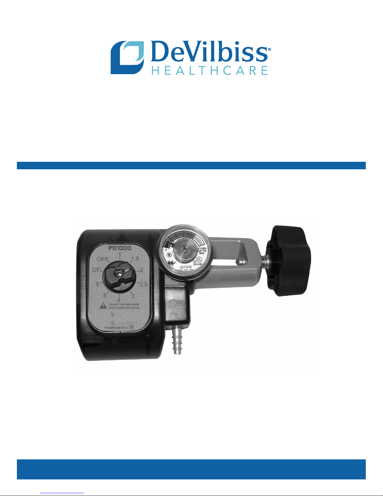
Remaining battery life can be observed as the Pulse
Indicator Lights illuminate with each breath (Figure 5).
5
Battery
Indicator
Lights
If the Green Pulse Indicator Light illuminates with each
breath, the batteries have sufcient power (8 or more
hours).
If the Red Pulse Indicator Light illuminates with each
breath, the batteries have between 4-8 hours of battery
life remaining.
If the Red Indicator Light illuminates continuously, the
batteries must be changed. The unit can be used on
the continuous ow "CF" setting if no batteries are
immediately available.
NOTE-Turn the Rotary Selector to the OFF setting
prior to changing batteries.
NOTE-The oxygen cylinder will not last as long in
continuous ow mode as it would in PulseDose mode.
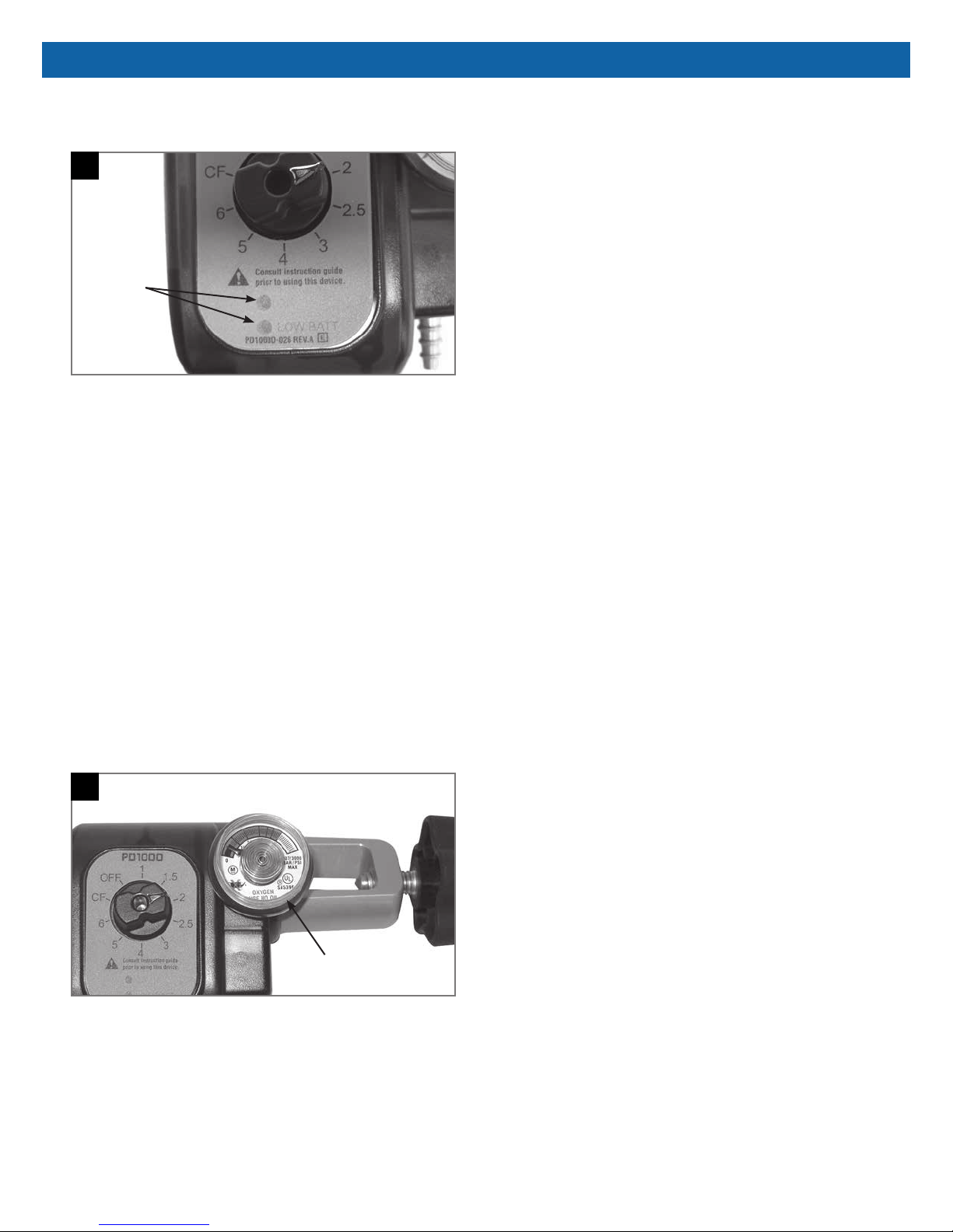
The contents gauge indicates the approximate amount
of oxygen left in the tank. It reads 1/4, 1/2, 3/4, and
full. It also has a red area to emphasize when the tank
needs to be changed (Figure 6).
IV. MAINTENANCE PROCEDURES
A. Testing
NOTE-The following should be performed after repair
or between patients
1. Install known good batteries.
2. Connect the unit to a pressurized oxygen cylinder
as described in Section III-A and connect a nasal
cannula.
3. Open the tank valve and verify that the PD1000
contents gauge indicates that there is a full tank.
4. Verify that there are no leaks around the tank seal
between the PD1000 and the oxygen tank.
5. Select any ow rate and simulate an inhalation
through the nasal cannula while verifying that a
"pulse" or bolus of oxygen is delivered with each
simulated breath.
6. Position the Rotary Selector to the "CF" position
and verify that the Continuous Flow Mode of
operation is functioning.
7. Verify that the top and bottom covers are not
cracked or broken.
8. Verify that the label can be read and is not
damaged.
9. Turn the Rotary Selector to the "OFF" position,
dose the tank valve, and remove PD1000 from
cylinder.
B. Cleaning
Wipe with a damp cloth having a maximum 5.25%
Sodium Hypochlorite (Bleach) or 3% Hydrogen
peroxide solution. Avoid getting uids or debris such as
sand or dirt inside the oxygen connections. Do not
immerse in water.
6
LT-1859
Contents
Gauge
4
Page 5

TROUBLESHOOTING
V. TROUBLESHOOTING
PROBLEM SOLUTION
Type I-
The unit does not deliver a
pulse with each inhalation
while properly connected to a
pressurized cylinder with the
post valve open.
Type II-
The regulator is leaking or the
gauge is broken or not reading
accurately.
Type III-
The cannula fitting is broken.
Type IV-
There is leakage between the
tank and the PD1000.
Type V-
Broken, damaged, or
non-functioning rotary selector.
1. Verify that the batteries are good and of specified type.
2. lf batteries are good, verify proper cannula connection and that patient is nose
breathing.
3. If yes, remove top and bottom covers (Section VI, C). Use a digital volt meter
and check the resistance across the Vacuum Switch (figure 7) with Rotary
Selector "OFF" when breath is simulated.
4. Refer to Section VI, E. If the resistance doesn't go to "0" when breath is simulated, change the vacuum switch.
5. If the resistance goes to "0" check the solenoid voltage (3VDC) when breath is
simulated and set to 6 LPM. (Refer to Figure 8)
6. If no voltage is present, change the PC Board.
7. If voltage is present, change the solenoid.
Refer to Section VI, C to remove the Regulator/Gauge Assembly and replace the
gauge or regulator.
Refer to Section VI, D to change the cannula fitting.
Close the tank valve, loosen the knob and verify that the post, the PD1000 regulator yoke and the tank surfaces are smooth and free of burrs. If they are smooth,
replace the regulator seal (#9286-RD). Refer to section VI, A.
Remove covers and replace rotary selector. Refer to Section VI, C.
7 8
Testing Vacuum Switch Testing Solenoid Voltage
5
LT-1859
Page 6

SERVICE INSTRUCTIONS
VI. SERVICE INSTRUCTIONS
A. Regulator Seal Replacement
Start by closing the tank valve so that no pressure is
supplied to the PD1000. Loosen the knob so that the
guide pins slide out of the indexing holes in the tank
post. Remove and replace the defective seal (Part #
9286-RD) (Figure 9).
9
PostGuide Pins
Regulator
Seal
B. Battery Replacement
NOTE-Turn the rotary selector to the "OFF" setting and
wait approximately 15 seconds prior to changing
batteries.
Open the battery door by pushing back on the latch
and lifting (Figure 10). Remove batteries and note the
polarity. The polarity is also indicated in the battery
compartment. Replace with standard "AA" alkaline or
NiMH batteries.
10
Battery Door
C. Cover/Regulator and Gauge Removal
Position the PD1000 face down so that the back cover
is facing up. Remove the 5 cover screws (Figure 11)
and then remove the rear cover. Stand the unit on its
side and (Figure 12) remove the circuit board/manifold
assembly. Then slide the front cover off the regulator.
The Rotary Selector will also lift out when the front
cover is removed (Figure 13). The regulator/gauge can
then be removed by disconnecting the regulator hose.
Refer to Section VII-Internal Parts.
11
Cover
Screws
12
Front Cover
Slot for Gauge
PC Board
Cannula Fitting
LT-1859
Battery Door
Latch
13
Knob Opening
Rotary Selector Knob
6
Page 7

SERVICE INSTRUCTIONS
D. Cannula Fitting Removal/Replacement
First remove the front and back covers.
NOTE-When removing or installing the cannula tting,
orient the manifold so the tting faces down to prevent
any debris from falling into the manifold which could
obstruct the continuous ow orice.
Use a 5/16" open end wrench and remove the cannula
tting by turning it counter-clockwise (Figure 12).
Replace with a new cannula tting and torque to 10
inch-lbs.
E. Solenoid/Vacuum Switch Testing and
Removal
Connect a piece of tubing to the cannula tting so that
a negative pressure can be created. Using a digital
voltmeter, check the resistance across the vacuum
switch as a negative pressure is created (Figure 7). If
the resistance doesn't go to "0" when a breath is
drawn, replace the vacuum switch.
If it goes to "0" but the solenoid doesn't open, check
the solenoid voltage (3VDC) (Figure 8). If there is no
voltage, change the PC Board. If there is voltage,
replace the solenoid (Figure 14).
To replace the vacuum switch, pull it apart from the
manifold/solenoid and the PC Board terminals (Figure
14). The vacuum switch can then be replaced by
pushing the manifold, vacuum switch, and PC Board
together. No tools are required.
14
PC Board
Vacuum Switch
Solenoid
Manifold
7
LT-1859
Page 8

PARTS AND ILLUSTRATIONS
VII. PARTS AND ILLUSTRATIONS
Solenoid/Manifold
PC Board
Rotary Selector
Regulator Hose
Vacuum Switch
Internal Parts
Regulator
Knob
Regulator/Gauge
Regulator Seal
INTERNAL PARTS LISTS
9286-RD Regulator Seal
PD1000D-604 Solenoid/Manifold
PD1000D-605 Vacuum Switch
PD1000D-606 Regulator/Gauge
PD1000D-607 PC Board
Regulator Hose
Top/Bottom Cover
Cover Screws
6x.25
Cannula Fitting
External Parts
EXTERNAL PARTS LISTS
PD1000D-601 Top/Bottom Cover
PD1000D-602 Rotary Selector
PD1000D-608 Battery Door
PD1000D-609 Regulator Knob
PD1000D-610 Cover Screws 6 x 1
PD1000D-611 Cover Screws 6 x .25
Cannula Fitting
PD1000D-612 Aluminum-2 lpm
PD1000D-613 Gold-3 lpm
PD1000D-614 Green-4 lpm
PD1000D-615 Blue-5 lpm
PD1000D-616 Red-6 lpm
Battery
Door
Cover Screws
6x1
LT-1859
8
Page 9

PNEUMATIC DIAGRAM / UNIT SPECIFICATIONS
VIII. PNEUMATIC DIAGRAM
IX. UNIT SPECIFICATIONS
Weight 14. 7 ounces (16.3 ounces with battery)
Dimensions 4.75"L x 3.4"W x 2.8"H (12.06 cm L x 8.64 cm W x 7.11 cm H)
Power Supply (2) Standard "AA" alkaline or NiMH. NOTE-Batteries other than alkaline
Operational Voltage Range 2.3 to 3.6V DC
Operating Temperature Range 5° to 40° C (41˚ to 104°F)
Operating Pressure Range 500 to 2250 PSIG (34 to 155 Bar) tank pressure
Operating Atmospheric Conditions 500 to 1020 millibar
Operating Humidity Range 0 to 95% R.H., non-condensing
Storage and Transportation Temperature Range 20° to 60° C ( -4° to 140° F)
Storage and Transportation Humidity Range Up to 95% R.H., Non-condensing
Degree of Protection Against Ingress of liquids None
Degree of Protection Against Electric Shock TYPE BF applied part
Power Requirements Average steady state “ON” current 1.6 uA. Batteries other than alkaline
Expected Shelf and Service Life (excluding batteries) 5 years based on 4 hours use per day at 20 BPM
Modes of Operation Continuous/Pulsed
Approval Body And Safety Standards IEC 601-1;CAN/CSA-C22.2 No. 601.1-M90 and IEC 601-1-2
US Patents 4,519,387; 5,755,224; 4,457,303
or NiMH are not recommended due to their limited capacities.
or NiMH are not recommended due to the capacity needed for operation
and battery life of the unit. Typical new battery life is 200 hours when
used at 25°C, 2 LPM and 20 BPM. Settings and breath rate will affect
battery life. After the Low Battery (flashing red) light illuminates, the unit
will continue to operate about four hours when used at 25°C, 20 BPM
and the 6 LPM setting. Settings, breath rate, and battery conditions will
affect use times. Refer to local regulations for battery recycling and/or
disposal requirements
X. PROVIDER’S NOTES
No routine calibration or service is required provided the device is used in accordance with the manufacturer’s
directions. Between patients wipe with a damp cloth having a maximum 5.25% Sodium Hypochlorite (Bleach) or 3%
Hydrogen peroxide solution. Avoid getting uids or debris such as sand or dirt inside the oxygen connections. Do not
immerse in water.
9
LT-1859
Page 10

PARTS RETURN AND ORDERING POLICY
XI. DEVILBISS GUIDANCE AND MANUFACTURER’S DECLARATION
WARNING
Medical Electrical Equipment needs special precautions regarding EMC and needs to be installed and put
into service according to the Electromagnetic Compatibility [EMC] information provided in the
accompanying documents.
Portable and Mobile RF Communications Equipment can affect Medical Electrical Equipment.
The equipment or system should not be used adjacent to or stacked with other equipment and that if
adjacent or stacked use is necessary, the equipment or system should be observed to verify normal
operation in the conguration in which it will be used.
NOTE– The EMC tables and other guidelines provide information to the customer or user that is essential in
determining the suitability of the Equipment or System for the Electromagnetic Environment of use, and in managing
the Electromagnetic Environment of use to permit the Equipment or System to perform its intended use without
disturbing other Equipment and Systems or non-medical electrical equipment.
Guidance and Manufacturer’s Declaration – Electromagnetic Emissions
This device is intended for use in the electromagnetic environment specied below. The customer or the user of this device should
assure that it is used in such an environment.
Emissions Test Compliance Electromagnetic Environment – Guidance
RF Emissions CISPR 11 Group 1
RF Emissions CISPR 11 Class B
Harmonic emissions
IEC 61000-3-2
Voltage uctuations /
icker emissions
N/A
N/A
Guidance and Manufacturer’s Declaration – Electromagnetic Immunity
This device is intended for use in the electromagnetic environment specied below. The customer or the user of this device should
assure that it is used in such an environment.
Immunity Test
Electrostatic discharge
(ESD) IEC 61000-4-2
Radiated RF
IEC 61000-4-3
Conducted RF
IEC 61000-4-6
IEC 60601 Test
Level
±6kV contact
±8kV air
3 V/m 80MHz to
2.5GHz
3 Vrms 150kHz to
80MHz
This device uses RF energy only for its internal function. Therefore, its RF emissions
are very low and are not likely to cause any interference in nearby electronic
equipment.
This device is suitable for use in all establishments including domestic and those
directly connected to the public low-voltage power supply network that supplies
buildings used for domestic purposes.
Compliance
Level Electromagnetic Environment - Guidance
Complies
Complies
N/A
Floors should be wood, concrete, or ceramic tile. If oors are covered
with synthetic material, the relative humidity should be at least 30%
Field strengths outside the shielded location from xed RF
transmitters, as determined by an electromagnetic site survey, should
be less than 3 V/m. Interference may occur in the vicinity of
equipment marked with the following symbol:
Immunity Test
Electrical fast transient
IEC 61000-4-4
Surge IEC 61000-4-5
Power frequency magnetic
eld IEC 61000-4-8
Voltage dips, short
interrupts and voltage
variations on power supply
input lines IEC 61000-4-11
This device has been tested to and meets the EMC requirements of EN60601-1-2. Do not place the device near other equipment or
devices that create or attract electromagnetic elds. Examples of such equipment are debrillators, diathermy equipment, CB radios,
microwave ovens, etc. Field strengths from xed transmitters, such as base stations for radio (cellular/cordless) telephones and land
mobile radios, amateur radio, AM and FM radio broadcast and TV broadcast cannot be predicted theoretically with accuracy. To
assess the electromagnetic environment due to xed RF transmitters, an electromagnetic site survey should be considered. If the
measured eld strength in the location in which the unit is used exceeds the applicable RF compliance level above, the unit should be
observed to verify normal operation. If abnormal performance is observed, additional measures may be necessary, such as reorienting
or relocating the unit.
IEC 60601 Test
Level
±2kV power line
±1kV I/O lines
±1kV differential
±2kV common
3 A/m Complies
>95% dip 0.5 cycle
60% dip 5 cycles
70% dip 25 cycles
95% dip 5 secs.
LT-1859
Compliance
Level Electromagnetic Environment - Guidance
N/A
N/A
N/A
Mains power quality should be that of a typical commercial or hospital
environment.
Power frequency magnetic elds should be at levels characteristic of
a typical location in a typical commercial or hospital environment.
Mains power quality should be that of a typical commercial or hospital
environment. If the user of this device requires continued operation
during power mains interruptions, it is recommended that the device
be powered from an uninterruptible power supply or battery.
10
Page 11

WARRANTY
XII. PARTS RETURN AND ORDERING POLICY
ALL DEFECTIVE COMPONENTS THAT ARE STILL UNDER WARRANTY MUST BE RETURNED TO THE FACTORY
IN SOMERSET, PA WITHIN 30 DAYS AFTER SHIPMENT OF THE NEW COMPONENTS. IF THE COMPONENTS
ARE NOT RECEIVED WITHIN THIS PERIOD, AN INVOICE WILL BE ISSUED TO YOUR ACCOUNT.
Before returning parts or units to the factory, call the DeVilbiss Healthcare Customer Service Department at 800-338-
1988 or 814-443-4881 to obtain a return authorization number. Include in the package a note indicating the return
authorization number along with your company name, address, phone number, and account number. The return
authorization number should also be written on the outside of the package. To expedite your order for warranty or non-
warranty parts, the following information should be given to the representative:
• Catalog Number
• Unit Serial Number
• Account Number
• Company name, address, and phone number
ORDERING INFORMATION
When ordering components, instruction guides, or service manuals the following must be provided:
• Unit Catalog Number
• Unit Serial Number
• Part Number
• Quantity Required
• Orders may be placed by calling Customer Service at 800-338-1988 / 814-443-4881
Technical Service 800-338-1988
XIII. WARRANTY
Three-Year Limited Warranty
DeVilbiss PulseDose Compact Conserving Device is warranted to be free from defective workmanship and material for
a period of three years from date of purchase. Any defective part(s) will be repaired or replaced at DeVilbiss
Healthcare's option if the unit has not been tampered with or used improperly during that period. Make certain that any
malfunction is not due to inadequate cleaning or failure to follow the instructions. If repair is necessary, contact your
DeVilbiss Healthcare provider or DeVilbiss Healthcare Service Department for instructions:
USA 800-338-1988 or 814-443-4881
Europe +49-621-178-98-230
NOTE-This warranty does not cover providing a loaner unit, compensating for costs incurred in rental while said unit is
under repair, or costs for Labor incurred in repairing or replacing defective part(s).
THERE IS NO OTHER EXPRESS WARRANTY. IMPLIED WARRANTIES, INCLUDING THOSE OF
MERCHANTABILITY AND FITNESS FOR A PARTICULAR PURPOSE, ARE LIMITED TO THE DURATION OF THE
EXPRESS LIMITED WARRANTY AND TO THE EXTENT PERMITTED BY LAW ANY AND All IMPLIED WARRANTIES
ARE EXCLUDED. THIS IS THE EXCLUSIVE REMEDY AND LIABILITY FOR CONSEQUENTIAL AND INCIDENTAL
DAMAGES UNDER ANY AND ALL WARRANTIES ARE EXCLUDED TO THE EXTENT EXCLUSION IS PERMITTED
BY LAW. SOME STATES DO NOT ALLOW liMITATIONS ON HOW LONG AN IMPLIED WARRANTY LASTS, OR THE
liMITATION OR EXCLUSION OF CONSEQUENTIAL OR INCIDENTAL DAMAGES, SO THE ABOVE LIMITATION OR
EXCLUSION MAY NOT APPLY TO YOU.
This warranty gives you specic legal rights, and you may also have other rights which vary from state to state.
11
LT-1859
Page 12

DeVilbiss Healthcare LLC
100 DeVilbiss Drive
Somerset, PA 15501-2125
USA
800-338-1988 • 814-443-4881
DeVilbiss Healthcare Ltd
Unit 3, Bloomfield Park
Bloomfield Road
Tipton, West Midlands DY4 9AP
UNITED KINGDOM
+44 (0) 121 521 3140
DeVilbiss Healthcare SAS
13/17, Rue Joseph Priestley
37100 Tours
FRANCE
+33 (0) 2 47 42 99 42
DeVilbiss Healthcare Pty. Limited
15 Carrington Road, Unit 8
Castle Hill NSW 2154
AUSTRALIA
+61-2-9899-3144
EC REP
0044
DeVilbiss Healthcare GmbH
Kamenzer Straße 3
68309 Mannheim
GERMANY
+49-621-178-98-230
DeVilbiss Healthcare LLC • 100 DeVilbiss Drive • Somerset, PA 15501 • USA
800-338-1988 • 814-443-4881 • www.DeVilbissHealthcare.com
DeVilbiss® and PulseDose® are registered trademarks of DeVilbiss Healthcare.
© 2014 DeVilbiss Healthcare LLC. 03.14 All Rights Reserved. LT-1859 Rev. B
 Loading...