

DeVilbiss OMX-5, OMX-6 Owner's Manual
Service Bulletin
SB-2-230-E
The
Right
Way
To
Finish"
Replaces SB-2-230-D
CE
OMX GRAVITY fEED HVLP
PAINT SPRAY
GUN
OWNER'S
MANUAL
IMPORTANT: Before
using
this
equipa
ment, read all
safety
precautions starting
on
Page 2. Other
safety
precautions are
also
noted throughout this manual. Keep
for future
use.
Record
the
gun
outfit
number
that
is
printed
on
the carton:
Gun
Outfit No: OMX-6
__
Record the Gun Model Number and
Date
Code
that
is engraved on
the
gun (Sea
diagram
below
for location.)
Gun
Model No: OMX-5
__
Gun
Date
Code:------
Products
shown
here are covered
by
one
or
more of
the
following U.S.
patent
numbers.
Other
U.S.
patents
are pending._ Foreign
patents
,._,-a
issued
or
Pending. D 351
,895;
0
349,559;
5,332,
156;
5,236,129
and
5,582,350.
Table
of
Contents:
Safety
Precautions
Description & Featums
Speciftcatlons
Assembly
Gun
Accessories
Disposable
Uner
PagaNo.
2
1
1
4
4
4
Paint
Filling
(with and without
liner)
Paint
Cup
Lid
4
5
6
6
7
8
9
9
9
Opera1lon
Description & Usage
LpperTrigger
Spraying Paint
(Quick
Start
Guide)
Cie1llnlng
By
Hand
By
Hand
With
Liner
By
Hand
Without
Liner
Gun
Washers
Troubleshooting
Spray
Patterns
Paint
Flow/Air
Problems
Paint
Cup
Uner
Problems
fsrts
R&placemsnt
Parts
Location
Diagram
Gun
Lube
Diagram
Oisassambly/Assembly
Air
Cap
8t
Spray
Haad
Spray
Head
Retaining
Ring
Grips
Lower
Trigger
Paint
Cup
Upper
Trigger
F!uiu
Tube
.D-.irVa!ve
8t
Internal
Parts
Misce!!aneous
Parts
Accessories
Warranty
10
12
13
13
13
14
15
15
15
16
16
20
21
23
24
26
28
23
32
35
36
DESCRIPTIONS
AND FEATURES
(1) Fluid Control (paint flow): Eliminates
the
need
for multiple
tips
and
needles
{2)
Air
Caps
Available:
#97HVlP*
for high
quality
performance
finishes
withal!
mate-
rials, including
!ow
V.O.C.
#98
LVLP*
has
low
air
consumption
for
use
with 2 to 3 HP
compressors
and
stan-
dard V.O.C.
materials.
(31
Disposable Paint Cup Liner
{not
shown):
Allows painting
in
any
position. Simplifies
clean-up.
(41
Ergonomic Design: Half
the
weight
of
a
metal
gun.
Ught
trigger
pull
force.
Upper
trigger for
easy
positioning
of
the
gun
on
horizontal
surfaces.
(5) Easy
Clean~up:
DuPont De!rin® p'aint
cup. Teflon
paint
passage,
{6)
Gun
holder: Holds gun for filling.
SPECIFICATIONS
t7l Gun Model
and
Date
Code:
See
illustra-
tion
below
for location.
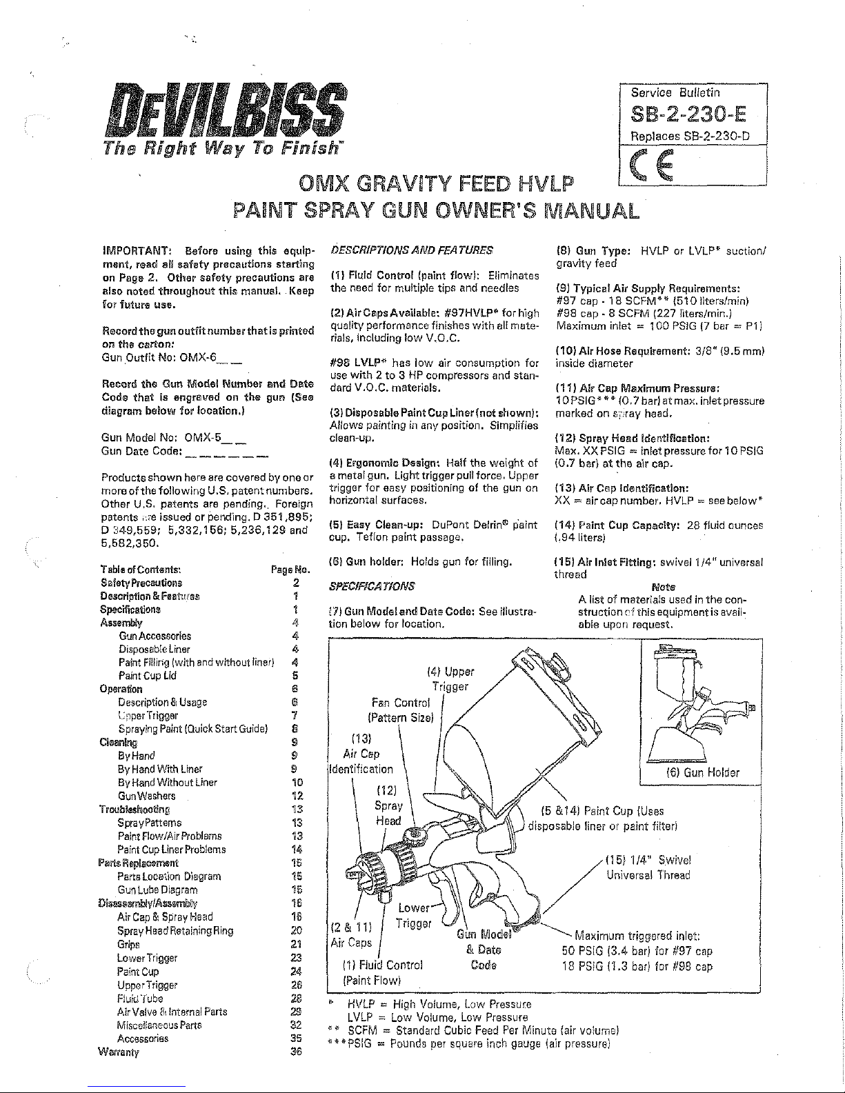
{4) Upper
{131
{8) Gun
Type:
HVLP
or
LVLP*
suction/
gravity feed
{9) Typical
Air
Supply Requirements:
#97
cap
-18
SCFM**
(510liters/min)
#98
cap-
8
SCFM
(227 liters/min.)
Maximum
inlet =
100
PS!G
{7
bar
= P1)
(10)
Air
Hose Requirement:
3/8"
{9.5 mm)
inside
diameter
( 11)
Air
Cap Maximum Pressure:
1 0
PSIG
jf
* * (0. 7 bar)
at
max. inlet
pressure
marked
on
sr··.,ray
head.
{12)
Spray
Head Identification:
Max.
XX
PSIG = inlet
pressure
for 1 0 PSIG
{0.7 bar} at the
air
cap.
{13)
Air
Cap Identification:
XX=
air
cap
number.
HVLP
=see
below*
(14) Paint Cup Capacity: 28 fluid
ounces
(.94liters)
!15) Air Inlet Fitting:
swivel1/4"
universal
thread
Note
A list
of
materials
used
in
the
con~
struction
cf
this
equipment
is avail-
able
upon
request.
15
&141
Paint
Cup
{Uses
disposable
liner
or
paint
filter}
i Control
(Paint
Flow)
*
HVLP = High
Volume,
Low
Pressure
LVLP = Low
Volume,
Low
Pressure
115)
1/4" Swivel
Universal
Thread
Maximum triggered inlet:
50
PSIG
(3.4
bar)
for
#97
cap
18
PSIG
{1.3
bar)
for
#98
cap
*
lf
SCFM =
Standard
Cubic Feed Per Minute
{air
volume)
***PSIG
=Pounds
per
square
inch
gauge
\air
pressure)
Page
2 88·2·230-E
SAFETY
PRECAUTIONS
This
manual
contains
information
that
is
important
for
you
to
know
and
understand.
This information
relates
to
USER
SAFETY and
PREVENTING EQUIPMENT PROBLEMS. To help
you
recognize
this
information,
we
use
the
following
symbols.
Please pay particular
attention
to
these
sections.
WARNIN<:
Note
important
safety
information
~
A hazard
that
may
cause
serious
injury or
loss
of
life.
Important
information
that
tells
how
to
prevel'lt damage
to
equipment, or how
to
avoid a situation
that
may cause minor
lnury.
You should pay special attention to this
information.
Hazard
Fire
Inhaling
Toxic
Substances
Explosion Hazard
~
incompatible
Materials
WARNING
The following hazards
may
occur during
the
normal use
of
this
equipment.
Please
reacl
the
following chant before using this equipment.
Causa
Solvents and
coatings
can
be
highly
flammable
or
combustible
especially
when
sprayed.
Certain materials
may
be
harmful
if
inhaled,
or
if
there
is
contact
with
the
skin.
Halogenated
hydrocarbon
solvents -for
example;
methylene
chloride
and
1, 1, 1
Trich!'oroethane are
not
chemicaHy
com-
patible
w'1th
the
aluminum
that
might
be
used
in
many
system components. The
chemical reaction caused
by
these
solvents reacting
with
aluminum
can
become violent and lead
to
an
equipment
explosion.
Safeguards
Adequate
exhaust
must
be provided
to
keep air tree
of accumulations
of
flammable
vapors,
Smoking
must
never
be
allowed
in
the
spray area.
Fire extinguishing
equipment
must
be
present
in
the
spray
area.
Static
discharges
musts
be
prevented.
Ground
atl
conductive
objects
in
the
spray
area, such
as
cleaning
solvent
bucket,
fire
extinguisher,
etc.
When
us'1ng
solvents
for
cleaning:
G Those used
for
equipment
flushing
musts
have a flash
point equal
to
or
higher
than
that
of
the
cOating.
,.,
Those used
for
general cleaning
must
have flash points
above
100'
F (37.8
C).
Follow the requirements
of
the
Material
Safety
Data
Sheet supplied
by
your
coating
material manufacturer.
Adequate
exhaust
must
be
provided
to
keep
the
air
free
of
accumulations
of
toxic
materials.
Use
a mask or
respirator
whenever
there
ls a chance
of
inhaling sprayed materials.
The
mask
must
be
compat-
ible
with
the
material being
sprayed
and its concentra-
tion. Equipment
must
be
as
prescribed
by
an industrial
hygienist or
safety
expert,
and
be
NIOSH
approved.
The
OMX
HVLP
Paint Spray Gun can be used
with
these
solvents.
·However,
aluminum
is
widely
used
tn
other
spray application
equipment,
such
as
material pumps,
cups and regulators,
valves,
etc.
Check
a!!
equipment
items before
use
and
make
sure
they
can
also
be
used
safely
with
these
solvents,
Read
the
label
or
data sheet
for
the
material
you
intend
to
spray.
If
in
doubt
as
to
whether
or
not a coating
or
cleaning material is
compatible, contact
your
material supplier.
SAFETY PRECAUTIONS
(conllnuedl
Hazard
General Safety
Nolse
i£-
..
-els
-Ear
Injury
Misuse
I
Cause
Improper
operation
or
maintenance
of
equipment.
A
continuous
A-weighted
sound pressure
level
of
this
spray gun may exceed
85
dB(A) depending on
the
air cap/spray
head
setup
being used. Sound levels
are measured using an impulse sound
level
meter
and analyzer, when the
gun is being used in a normal spraying
application.
SB-2-230-E
Page
3
Safeguards
Operators
should be given adequate training in the safe
use
and maintenance
of
the
equipment
{in accordance
with
the
requirements
of
NFPA-33, Chapter
15
in U.S.).
User
must
comply
with
all local and national codes
of
practice
and insurance
company
requirements govern-
ing
ventilation,
fire precautions,
operation,
maintenance
and housekeeping. In
the
U.S., these are OSHA Sections
1910.94
and
1910.107
and NFPA-33).
Always
wear
ear
protection
when
using
the
gun.
Details
of
actual noise levels produced
by
the
various air
cap/spray
head setups are available
upon
request.
~
A!! spray guns
project
particles
at
high
velocity
and
must
never
be aimed
at
any
part
of
the
body.
e
Never
exceed
the
recommended
safe
working
pressures
for
any
of
the
equipment used.
o The
fitting
of
non~recommended
or
non-original accessories or spare
parts
may
crate hazardous conditions.
~Before
dismantling
he
equipment
for cleaning
or
maintenance all pressure, air and materials,
must
be
isolated and released.
The disposal
of
waste
materials
must
be carried out in
an
approved manner. Burning
may
generate toxic
fumes,
The removal
of
waste
solvents and
coating
materials should be carried
out
by
an
authorized
local
waste
disposal service.
Cumulative
Trauma
Dlsorders(CT!l's)
"(TO'S" ,ormulculo-
s~-a~letal
disorders,
!n·
valva damage
to
the
hands,
wriat,
elbows.,
shoulders,
neck
&back.
Carpal
tunnel
syndrome
and
tendinitis
{such
as
tennis
elbow
or
rotator
cuff syndrome)
011re
eJmmp!es
of
CTD's,
Use
of hand too!s may
ca·use
cumu!ative
trauma disorders {CTD's),
CTD'
s, when using
hand
tools, tend to affect
the upper extremities. Factors
which
may
increase the
risk of developing a
CTD
include:
1.
H'1gh
frequency of the activity,
2.
EJ(Cessiveforce,
such
as
gripping,
pinching,
or
pressing with the
hands
and
fingers.
3.
Extreme
or
awkward finger, wrist
or
arm positions.
4.
Excessive duration of the activity,
5.
Tool vibration.
6.
Repeated
pressure
on a body
part.
7.
Working
in
cold
temperature:::.
CTD' scan also
be
caused
by
such
activities
as
sewing, golf, tennis
and
bowling, to
name
a few.
Risk
is
reduced
by avoiding
or
lessening factors 1 ~ 7.
Pain,
tingling,
or
numbness in the shoulder, forearm, wrist,
hands
or
fingers, especiallydurir1!]the night, may
be
early symptoms of a
CTD.
Do
not ignore them. Should
you
experience
any
such symptoms,
see a physic;.-m
immediately.
Other early symptoms may include vague discomfort
in
the
hand,
loss of
manual
dexterity,
and
nonspecific pain
in
the
arm.
Ignoring early symptoms
and
continued repetitive
use
ot
the arm, wrist
and
hand
can
lead to serious disability,
Page
4 88·2·230-E
ASSEfi//BL Y •
GUN
ACCESSORIES
"(3)
Quick
Disconnects
'121Hand
Tightened
Disposable
Air
Filter
Use
only highflow ----~
HVLP
quick
connects
such
as
OsVHbiss
typesonPg. 35.
~(4.
3/8"
{9.6
mm)
Air
Hose
(1)
Attach
air adjusting valve with gauge
to
base
of
gun handle.
(2)
Attach
dis:cosabte air filter. Hand
tighten
only.
Do
not use tools!
{3)
Attach
your quick disconnect*.
rlnly
tighten
snugly
to
air filter.
Do
not
overtighten.
(4)
Attach
your air hose (recommended
3/8"
(9.5
mm) inside diameter).
Note
This
method
of
assembly will
allow
you
to
measure the actual
inlet
gun pressure
after
all pres-
sure
drops
in
the
air
inlet
line and
hose.
ASSEfi//BL
Y.
DISPOSABLE CUP LINER
Note
This paint cup can
be
used
with
or
without
the
paint liner. Skip
to
Column
3,
Paint
Filling
Assemby,
if
not
using the paint
liner.
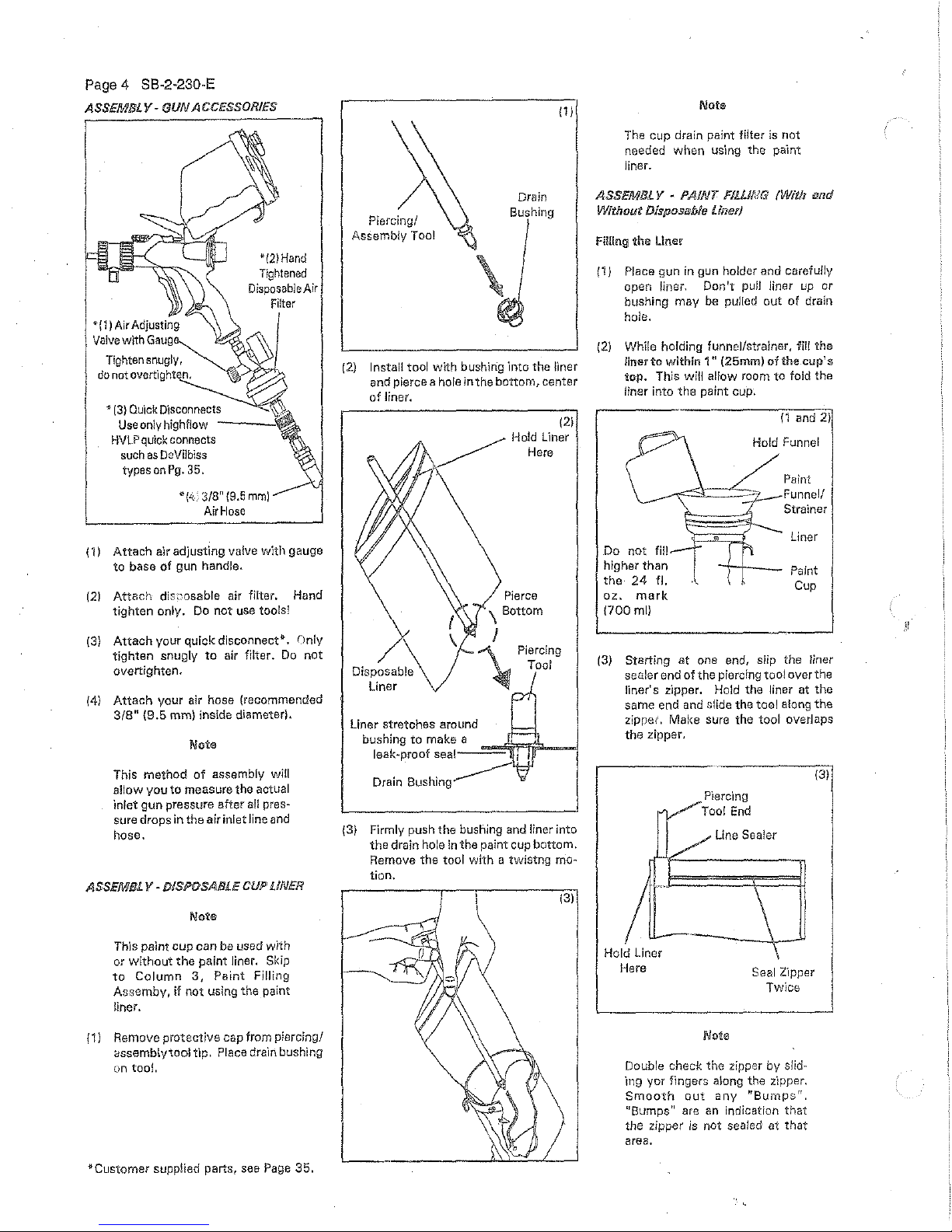
{1)
Remove protective cap from piercing/
assemb!ytool
tip.
Place drain bushing
on too!.
*Customer supplied parts,
see
Page
35.
111
Note
The
cup drain paint filter is
not
needed when
us'1ng
the paint
liner.
Drain
ASSEfi//Bl V •
PAINT
Flllllc!G
!With
and
Piercing/
Assembly Tool
\
Bushing
(2.)
Install tool
with
bushing
into
the liner
and pierce a hole in the bottom, center
of
liner.
Disposable
Liner
(21
Hold Liner
Here
Piercing
Tool
{3) Firmly push the bushing and
liner into
the
drain hole
in
the paint cup bottom.
Remove the
tool
with a twistng
mo~
tion.
Without Disposable Liner/
filling
the
liner
{1)
Place gun in gun holder and carefully
open liner.
Don't
puJJ
liner
up
or
bushing
may be pulled
out
of
drain
hole.
{2)
While holding funnel/strainer,
fW
the
liner
to
within
1"
(25mm)
of
the cup's
top. This will allow
room
to
fold the
liner into
the
paint cup.
Do
not
fill
higher than
the
24
fl.
oz.
mark
(700mll
(1
and
21
Hold Funnel
Paint
Funnel/
Strainer
Liner
-;--+---
Paint
Cup
(3)
Starting
at
one end, slip the liner
sealer
end
of
the piercing tool over the
liner's zipper. Hold the liner at the
same end and
s!ide the tool along
the
zipper. Make sure the
tool
overlaps
the
zipper.
Hold Liner
Here
Piercing
Too!
End
Line Sealer
Seal
Z'1pper
Twice
Doub!e
checl<
the zipper
by
slid*
ing
yor
fingers
along the z'1pper.
Smooth
out
any
"Bumpsrr.
"Bumps" are
an
indication
that
the
zipper
is
not sealed at
that
area.
131
ASS/£Mfll V-
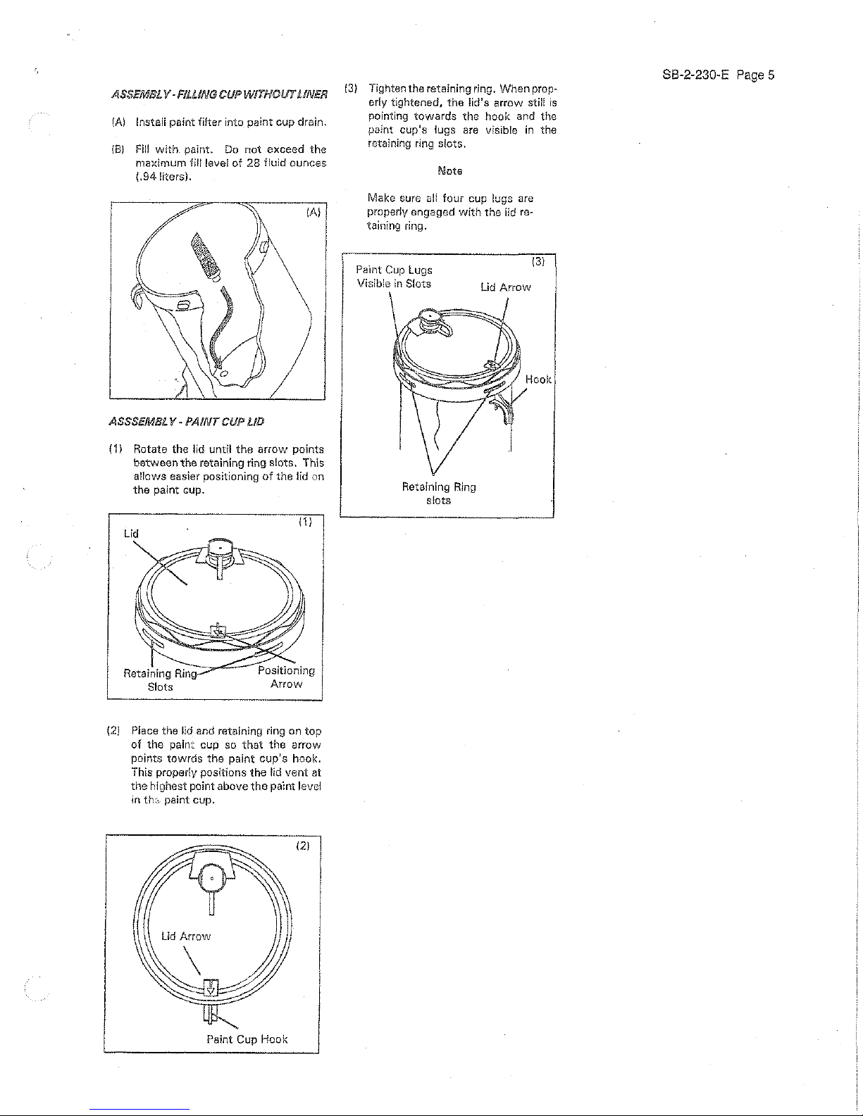
FILLING
CUP
WITHOUT UNEfl
(A)
lnstalf paint
filter
into paint cup drain.
(8)
Fill
with
paint.
Do
not
exceed the
ma;dmum fill level
of
28
fluid ounces
(.941itersl.
{3)
Tighten the retaining ring. When prop-
erly tightened, the lid's arrow still
is
pointing
towards
the
hook and
the
paint cup's lugs
are
visible
in
the
retaining ring slots.
Note
Make sure
a!!
four cup lugs
are
(A)
properly engaged
with
the
lid re-
taining ring.
ASSSEMlll
ll-
PAINT
CIJP
LID
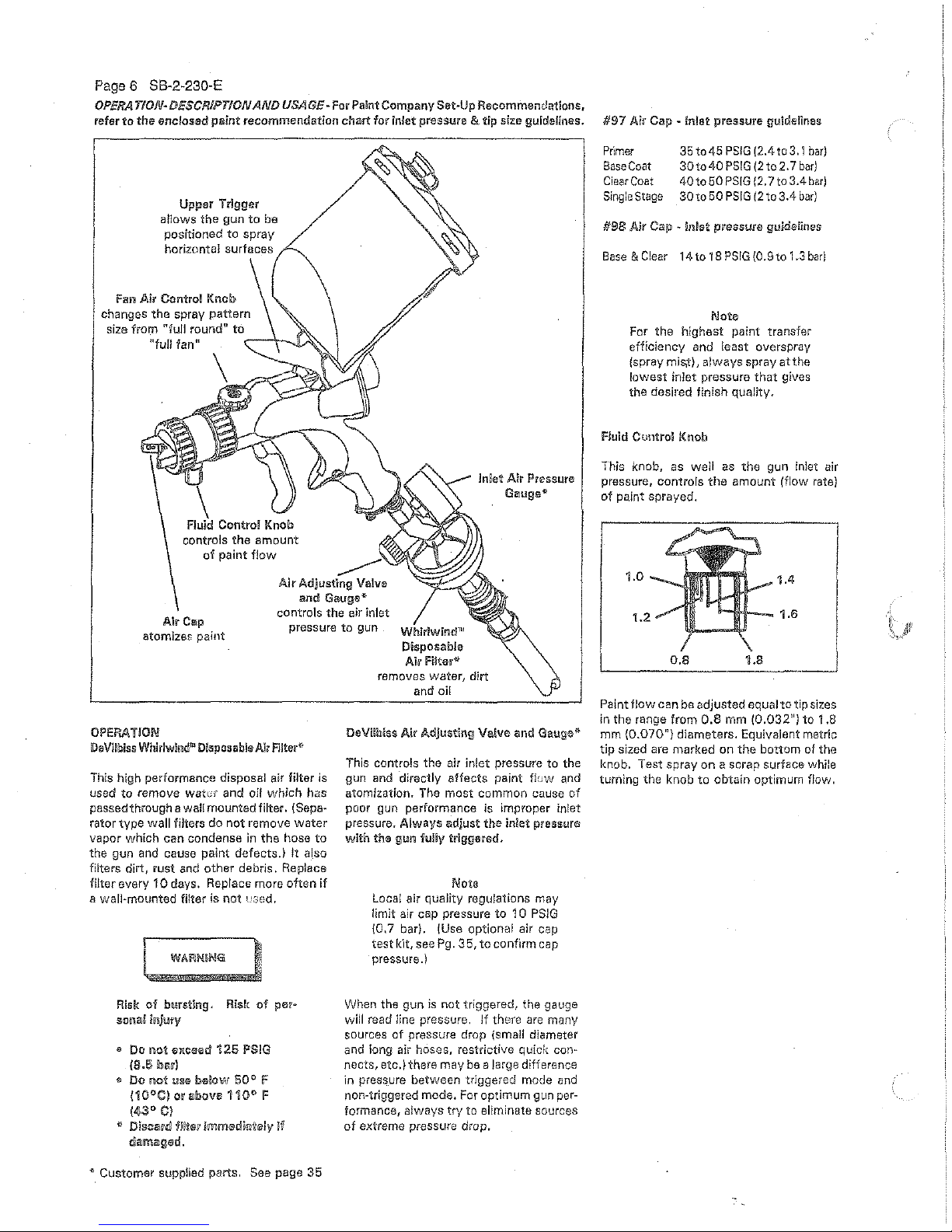
{1)
Rotate
the
lid
until
the
arrow
points
between
the
retaining ring slots. This
allows easier positioning
of
the
lid
on
the
paint cup.
(11
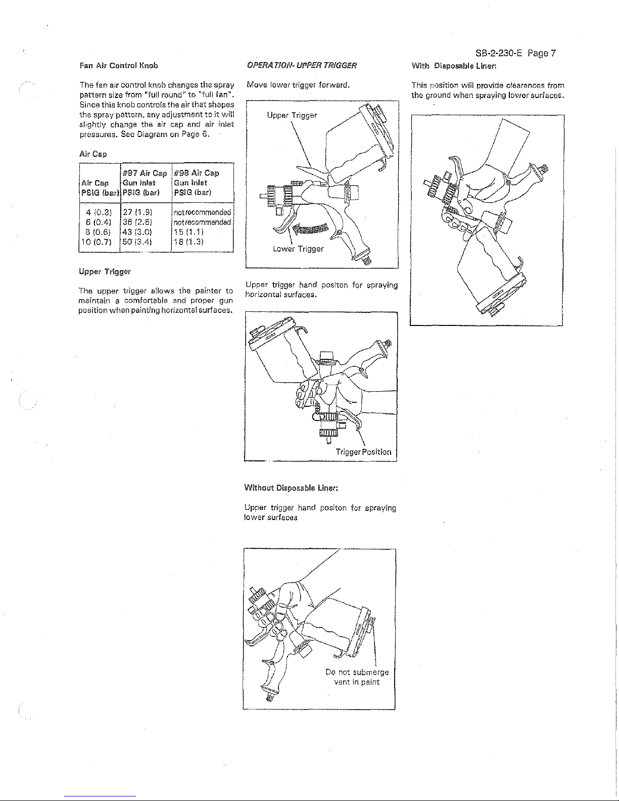
(2)
Place the lid and retaining ring on
top
of the pain: cup so
that
the arrow
points towrds the paint
cup's
hook.
This properly positions
the
lid
vent
at
the
highest point
above
the
paint level
in
th:-,.
paint cup.
121
Paint Cup Hook
Pa·lnt
Cup
lugs
Visible
in
Slots
Retaining
Ring
slots
131
Hook
88-2-230-E
Page
5
Page 6 88·2·230-E
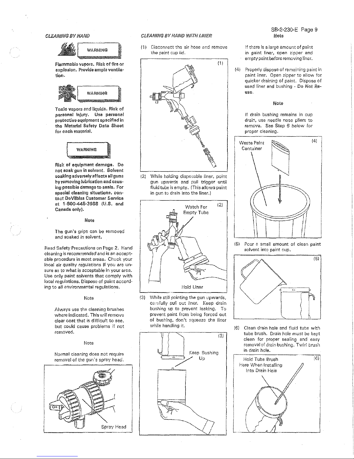
OPERATION~
DESCRIPTION
AND
USAGE~
For Paint
Company
SetAJp
Recommendations,
refer
to
the
enclosed
paint
recommendation
chart
for inlet
pressure
& tip size guidelines.
Upper
Trigger
allows
the
gun
to
be
positioned to
spray
horizontal surfaces
Fan Air Control Knob
changes the spray
pattern
size from
"full
round"
to
"full tan"
~--1.-U
\
Fluid Control Knob
controls
the
amount
of
paint
flow
-----
Inlet Air Pressure
Gaugeii
Air Adjusting Valve
and
Gauge*
controls
the
air inlet
pressure
to
gun
WhlriwintP1,1
Disposable
Air
Filtar*
OPERATIOIII
!DeVIlbiss
Whlrlwinc!l
11
Disposable
Air
FUterr'
This high performance disposal air filter is
used
to
remove
water
and oil
which
has
passed through a
waH
mounted filter. (Sepa·
rator
type
wall filters
do
not
remove
water
vapor which can condense
in
the
hose
to
the gun and cause paint defects.)
It
also
filters
dirt, rust and
other
debris. Replace
filter everv
10
days. Replace more
often
if
a wall·mounted filter is
not
used.
WARIN!N"G
Risk
of
bursting.
Risk
of
pefo
sona! inJury
Ill
Do
no~
exceed
125
PS!G
(8.5
bov)
til Do
not
us®
b®low
50
° F
(10°C)
orabov•110°
F
(43°
Ci
~
DlscB~n~
filtsc·
SmmsdiSJtely
If
damagerdl.
"'
Customer
supplied parts.
See
page
35
removes
water,
dirt
and
oil
DeVilbiss Air Adjusting Valve
and
Gauge*
This controls the air intet pressure
to
the
gun and directly
affects
paint f!uw and
atomization. The
most
common
cause of
poor gun performance is improper inlet
pressure. Always
~djus'l:
the
inlet pressure
with
the gun
fuliy
triggered.
Note
Local air quality regulations may
limit air cap pressure
to
1 0
PSJG
\0,7 bar). (Use optional air cap
test
kH,
see
Pg. 35,
to
confirm cap
pressure.)
When
the
gun
is
not
triggered,
the
gauge
will
read line pressure.
If
there
are
many
sources
of
pressure drop (small diameter
and long air hoses, restrictive quick con*
nects, etc.)
there
may
be
a large difference
in pressure between
triggered mode
and
non-triggered mode. For optimum gun per·
formance,
always
try to eliminate sources
of
extreme pressure drop.
#97
Air Cap - Inlet
pressure
guidelines
Pr'lmer
Base
Coat
Ciear
Coat
Single
Stage
35
to 45
PSIG
(2.4
to
3. I bar)
30to
40
PSIG
(2
to
2.
7
bar)
40 to
50
PSIG
12.7
to
3.4
bar)
30
to
50
PSIG
12
to
3.4
bar)
#98
Air Cap - inlet
pressure
gu!delines
Base
&Clear 14to18PSlG(0.9to1.3bar)
Note
For
the
highest paint transfer
efficiency and least overspray
(spray
mis,t),
always
spray at
the
lowest
inlet pressure
that
gives
the desired finish quality.
Fluid Cuntrol Knob
This knob,
as
well
as
the gun inlet air
pressure, controls
the
amount (flow rate)
of
paint sprayed.
1.4
1.6
0.8
1.8
Paint
flow
can
be
adjusted
equal
to
tip
sizes
in the range from
0.8
mm
(0.032")
to
1.8
mm
(0.070")
diameters.
Equivalent metric
tip
sized are
marked
on
the
bottom
of the
knob. Test spray
on
a scrap surface while
turning
the
knob
to
obtain optimum flow.
Fan l\l1 Conlrol Knob
OPERA
T/Qf/-
UPPER
TRIGGER
The fan air control knob changes
the
spray
Move
lower trigger forward.
pattern size from
"full round''
to
"full
fan",
Since
this
knob
controls
the
air
that
shapes
the
spray
pattern,
any
adjustment
to
it
will Upper Trigger
slightly change the air cap and air inlet
pressures. See Diagram on Page 6.
Air
Cap
#97
Air
Cap
#98
Air
Cap
Air Cap
Gun
inlet
Gun
lnle1t
PS!G (bar) PSIG (bar)
PSIG (ba1)
4 (0.3)
27
(1.9)
not
recommended
6
(0.4)
36
(2.5)
not
recommended
8
(0.6)
43
(3.0)
15
I 1
.1
I
10
(0.7)
50
(3.4)
18
(1.3)
Upper
Trigge~
The upper trigger allows the painter
to
maintain a comfortable and proper gun
position
when
painting horizontal surfaces.
Upper
trigger hand positon for spraying
horizontal surfaces.
Trigger Position
Without
Disposable Liner:
Upper trigger hand positon for spraying
tower surfaces
Do
not submerge
vent
in
paint
SB-2·230-E
Page
7
With Disposable Liner.
This r::osition will provide clearances
from
the
ground
when
spraying
lower
surfaces.

Page
8 SB-2-230-E
OPERATION-SPRAYING
PAIN/
(3)
Fill
Paint Cup
(5)
Purge air from disposable liner using 50
PSIG
13.4 bar).
{2)
"tighten
Air
Cap
Ring
181
Adjust spray
pattern
size.
16)Adjust Inlet
Air
Pressure
(1)
f{ead all
instructions
and safety
pre~
cautions in
the
previous sections.
Pressurized liquids. Risk
of
eye
injury, Wear eye proitecton
andl
point gun
away
from
persons.
~I
WARNING
•
'<WI·-
IS~
Flammable vapors.
Risk
offlr-:·)
or
explosion. Provide ample venti-
lation.
Toxic
Vill.POfS
!U!d
liqulc!!s.
Risk
oi
persontl'l~
injury,
Use
the
protec-
tive
equipment
spec!fled
in
the
paint's
materia!
safety
data
sheets.
121
13)
141
15)
161
171
18)
191
Cup drain
at
highest point
1.8
Setting,
Longest Line
50
PSIG
Triggered
{4}Connect
Air
Tighten air cap ring and spray
head
ring.
Install disposable liner or paint filter.
(Page
4}. Fill paint cup.
Connect
to
proper
air supply
(Page 1 ).
When using liner, purge air
to
allow
painting
in
any position.
*Adjust
gun
as
shown
in
inset {5),
* Turn cup upside
down.
* Trigger until constant paint
flow
is
observed.
* Postion gun
for
painting and
follow
Steps 6,
7,
& 8.
While triggering the gun, adjust inlet
air
pressure (page 6).
Adjust
the
paint flow (page 6).
Adjusi:
the
spray
pattern
size (Page 7).
Clean gun immediately after painting
(Page
9).
{10) Wipe gun dry.
B!owoutthepaintand
tlir passages with air.
(11) A!
ways
store the gun
with
the cup lid
and
air
cap
installed.
Note
Do
not
store
the
gun
with
paint
or
solvent in
the
cup.
CLEANING
BY
HAND
WARNING
flammable vapors.
Risi{
of
fire or
explosion.
Provide
ample
ventila-
tion.
WARNING
Toxic vapors and liquids. Risk
of
personal injury. Use personal
protective
equipment specified
lUi
the
Msterial Safety Data
Sheet
for
each
material.
WARNiNG
Risk
og
equipment
damage.
Do
not
soak gun
in
solvent. Solvent
soaking adversely affects
all
guns
by
removing lubrication
a.nd
caws-
ing possible damage
to
seals.
For
spacial cleaning situations, con-
tact
DeVIlbiss Customer Service
a!
1-800-445-3988
(U.S.
and
Canada
only}.
Note
The
gun's
grips can be removed
and soaked
in
solvent.
Read
Safety
Precautions on Page
2.
Hand
cleaning
is
recommended and is
an
accept-
able
procedure in most areas. Check your
local air quality regulations
if
you
are un-
sure
as
to
what
is acceptable in
your
area.
Use
only
paint solvents
that
comply
with
local regulations. Dispose of paint accord-
ing
to
all
environmental regulations.
Note
Always
use the cleaning brushes
where indicated. This
will remove
clear
coat
that
is
difficult
to
see,
but
could cause problems
if
not
removed.
Note
Normal cleaning does
not
require
removal
of
the gun's spray head.
CLEANING
BV
HAND
WITH
liNER
/1) Disconnect
the
air hose and remove
the
paint cup lid.
111
\
\
(2) While holding disposable liner, point
gun upwards and
pull
trigger
until
fluid
tube is
empty.
{This
allows
paint
in gun to drain into the liner.)
Watch For
Empty Tube
Hold Llner
121
(3) While still pointing the gun
upwards,
CCL"Dfully
pull
out
liner. Keep drain
bushing up to prevent
ieaking, To
prevent paint from being forced
out
of
bushing, don1t squeeze
the
liner
while handling it.
[]
(3)
Keep Bush1ng
/Up
SB·2-230·E Page 9
Note
If there
is
a large amount
of
paint
in paint liner, open zipper and
empty paint
before removing liner.
(4) Properly dispose
of
remaining paint in
paint
liner, Open zipper
to
allow
for
quicker draining
of
paint.
Dispose
of
used liner and bushing • Do
Not
Re-
use.
Note
If
drain bushing remains in cup
drain, use needle nose
pliers
to
remove. See Step 6 below for
proper cleaning.
Waste
Paint
Container
141
(5) Pour a small amount
of
clean paint
solvent into paint cup.
(51
rrr
(6)
Clean drain hole
and
fluid tube
with
tube brush. Drain hole
must
be
){ept
clean
for proper sealing
and
easy
removal
oi drain bushing.
Twirl
brush
in drain hole.
Hold Tube Brush
Here When
Installing
Into Drain Hole
l
I
Page
1 0 88·2-230-E
CLEANING
BY
HAND WITH LINER
(con'!)
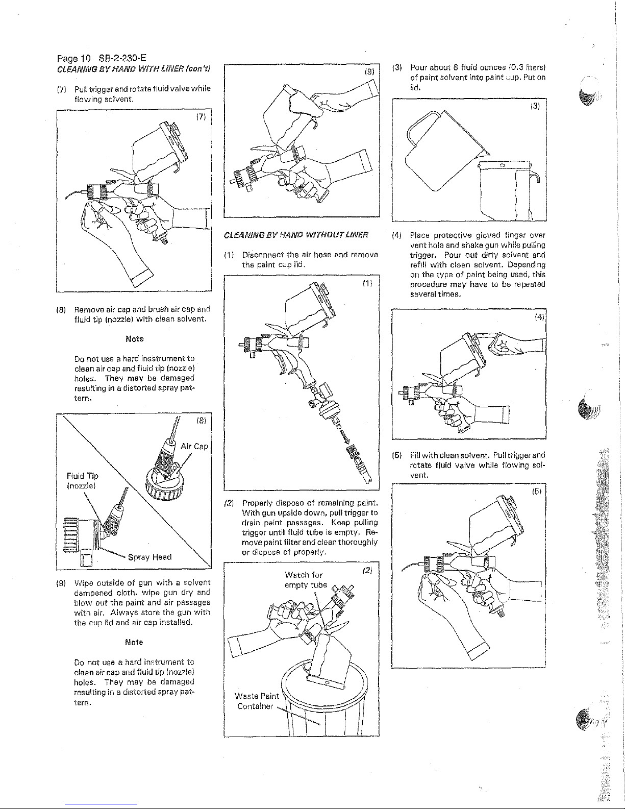
{7)
Pull trigger and rotate fluid valve while
flowing solvent.
171
(8)
Remove air cap and brush air cap and
fluid tip (nozzle)
with
dean
solvent.
Note
Do
not
use
a hard insstrument
to
clean air cap and fluid
tip
(nozzle)
holes. They
may
be damaged
resulting
in
a distorted spray
pat~
tern.
Fluid Tip
{nozzle)
Spray Head
(9)
Wipe outside
of
gun with a
solvent
dampened cloth. wipe gun dry and
blow
out
the
paint
and
air
passages
with
air.
Always
store
the
gun with
the
cup
lid
and
air
cap
instatled.
Note
Do
not
use a hard inc:trument
to
clean air cap and fluid
tip
{nozzle)
holes. They
may
be
damaged
resulting
in
a distorted spray pat-
tern.
191
CLEANING
BY
NAND W/1HOIJT LINER
(
1}
Disconnect
the
air hose and remove
the
paint cup lid.
(2) Properly dispose
of
remaining paint.
With
gun upside
down,
pull trigger
to
drain paint passages. Keep pulllng
trigger until f!uid
tube
is empty,
Re~
move paint
filter
and clean thoroughly
or
dispose
of
properly.
{3)
Pour about 8 fluid ounces (0.3 liters)
of
paint solvent into paint
wup.
Put
on
lid.
131
{4)
Place protective g!oved finger over
vent
hole and shake gun while pulling
trigger, Pour
out
dirty
solvent
and
refill with clean solvent. Depending
on
the type
of
paint
being used, this
procedure
may have to be repeated
several times.
141
(5)
Fill
with clean solvent. Pull trigger
and
rotate fluid valve while flowing solvent.
CLEANING IJY HAND
WITHOUT
LINE!/
{continued)
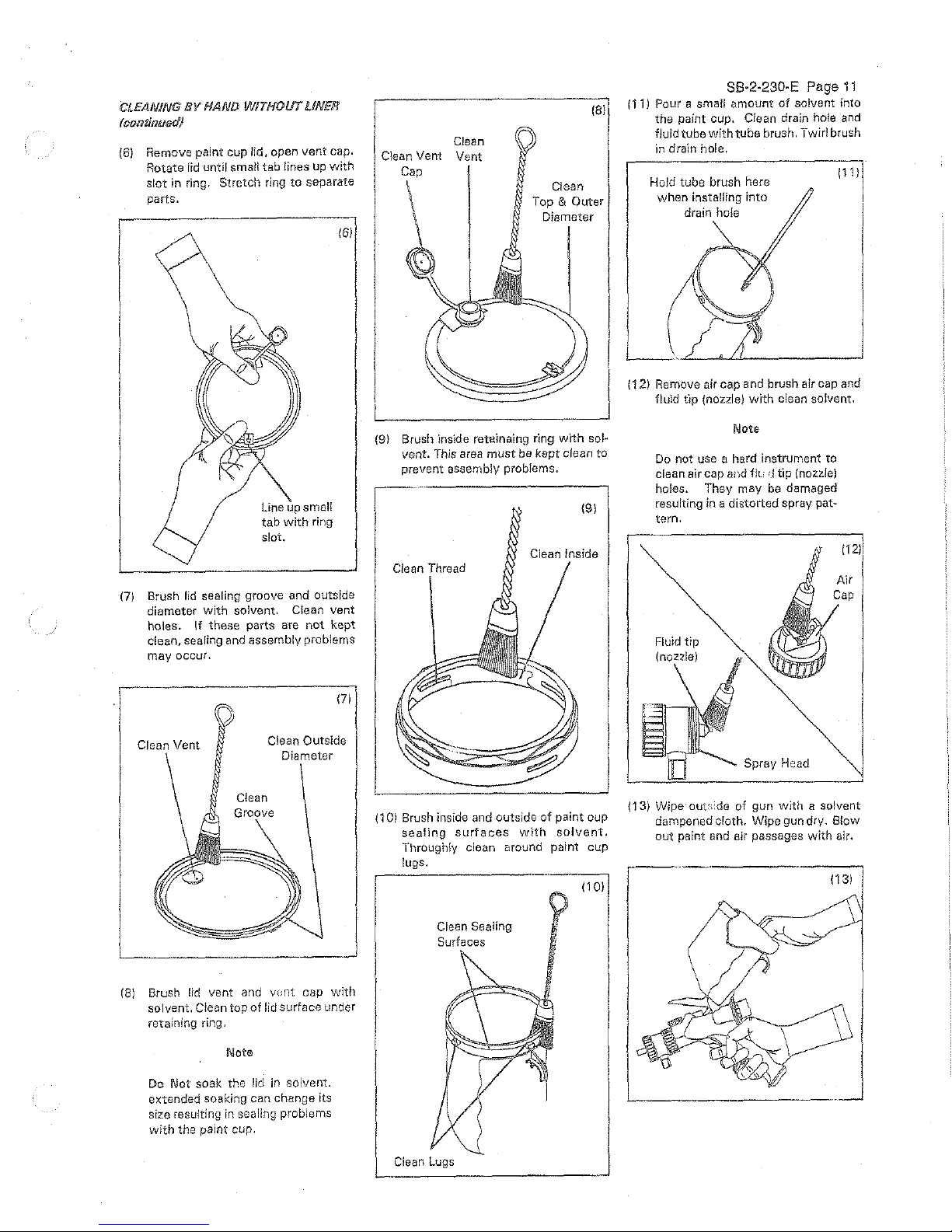
(6)
Remove paint cup lid, open vent cap.
Rotate lid until smatl tab lines up
with
slot
in
ring.
Stretch
ring
to
separate
parts.
Line
up
small
tab
with
ring
slot.
161
(7)
Brush
lid
sealing groove and outside
diameter
with
solvent. Clean vent
holes.
If
these
parts are not kept
clean,
searing and
assembly
problems
may occur.
171
Clean Outside
Diameter
L____
__
j
(8)
Brush
lid
vent and
vcnt
cap
with
solvent.
Clean
top
of
lid
surface
under
retaining ring.
Note
Do Not soak the lid
in
solvent.
extended
soaking
can
change
its
size resulting in sealing probiems
with the paint cup.
Clean
Clean Vent Vent
Cap
(81
C!ean
Top &
Outer
Diameter
88·2·230-E
Page
11
(11
J Pour a small amount
of
solvent into
the
paint cup. Clean drain hole
and
fluid tube
with
tube brush. Twirl brush
in drain hole.
Hold tube brush here
when installing
into
drain hole
1111
I
f
1121
Re:ove
air
cap and brush
air
cap and
fluld tlp (nozzle)
with
clean solvent.
L---------------~
(9) Brush inside retainafng ring
with
sol·
vent. This area
must
be
kept clean to
prevent assembly problems.
(91
Ciean Inside
Clean
{1
0)
Brush inside and outside
of
paint cup
sealing
surfaces
wlth
solvent.
Throughly clean around paint cup
lugs.
Clean Sealing
Surfaces
Clean
Lugs
(101
Note
Do
not use a hard instrument to
clean air cap
and
f!t.:
,_1
tip {nozzle)
holes. They may
be
damaged
resulting
in a distorted spray
pat~
tern.
Fluid
tip
Spray Head
(13)
Wipe· out:. ide of gun
with
a solvent
dampened erath. Wipe gun dry. Blow
out
paint and air passages
with
air.
1131
 Loading...