

DeVilbiss MSV-531-46FF, MSV-531-28FX, MSV-531-33FF, MSV-531-33FX, MSV-531-46FX Service Bulletin
...
MSV-531 HIGH VOLUME LOW PRESSURE SPRAY GUN
IMPORTANT: Before using this equipment, read all Safety Precautions and
Instructions. Retain for future use.
DESCRIPTION
The MSV-531 is a slightly smaller, lighter
HVLP spray gun, capable of high production. It can be used with a wide variety of
finishing materials. All models are designed to provide maximum transfer efficiency by limiting air cap pressure to 10 psi
(complies with rules issued by SCAQMD
and other air quality authorities). The gun
is intended for use with pressure feed paint
supply only.
Note
The MSV-531 spray gun is not suitable for highly abrasive materials (i.e.
porcelain enamel, certain mica paints,
etc.). Premature fluid tip and needle
wear will occur. We recommend
carboloy fluid tips (AV-617 series) and
needles (JGA-409 series) for use with
these coatings.
Most finishing materials can be atomized
with the 28 or 33A air caps. The 28 or 33A
air caps should be used where possible as
they consume less air volume (CFM) and
have slightly better transfer efficiency than
the 46MP and 83MP air caps. However,
more difficult to atomize materials (i.e. low
VOC's) or high flow applications (over 12
oz./min.), are ideal for the 46MP (maximum
performance) air cap, fluid tip and baffle
combination. Also available is the 83MP
(maximum performer) for even higher flows
(17 oz. /min. and above), and viscosities.
Refer to the air cap chart for more information. Spray guns with a 28 or 33A nozzle
combination can be converted to 46MP or
83MP if desired.
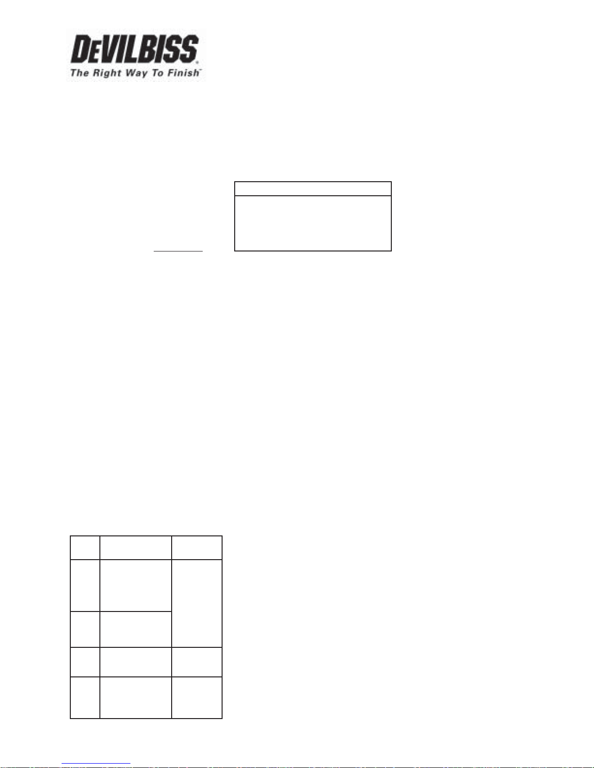
AIR CAPS - PATTERNS - APPLICATIONS
Air Cap *Typical Pattern Size Typical
No. and Shape Application
28 11" long, straight-
sized, similar to
#704 air cap. Most
common
finishing
materials
33A 9" long, tapered up to 12
ends similar to #30 oz./min.
air cap.
46MP 11" long, straight- Low VOC
sided, similar to materials, 12
#704 air cap. to 16 oz./min.
83MP 13" long, straight- Low VOC
sides, similar to materials,
#765 air cap. 17 oz./min.
and above.
*Actual pattern length dependent upon
fluid tip ID, fluid flow rate, viscosity, air
pressure, and fan pressure.
Operating Pressures:
Air: 100 PSI Maximum (see following chart)
Fluid: 150 PSI Maximum
Standard Combinations Available:
Order No. * Gun Inlet Pressure
MSV-531-28FF, FX 50 PSI
MSV-531-33FF, FX 50 PSI
MSV-531-46FF, FX 50 PSI
MSV-531-83D, E 65 PSI
•MSV-531-3-46FF, FX 50 PSI
• Models include 300 grade stainless fluid tip
with UHMW poly. needle seat and 300
stainless needle.
* Approximate pressure required to achieve
10 PSI air cap pressure.
Gun models are available with 400 grade
stainless fluid tips and 300 series stainless
needles, and are suitable for most common
coating materials. Select model combinations (see above) are available with 300 grade
stainless fluid tips and needles, and can be
used with waterborne materials or more
corrosive coatings (6.0 pH or above).
These gun models will produce approximately
10 psi cap pressure at the corresponding gun
inlet pressure, as measured at the gun inlet.
Air cap test kits (see Accessories) should be
used to insure 10 psi air cap pressure is not
exceeded.
Note
This gun may be used with chlorinated solvents; but, see additional
warnings on page 2.
INSTALLATION
Do not use more pressure than is necessary
to atomize the material being applied.
To provide optimum performance and assure compliance with all air quality regulations, an air cap test gauge kit is available
to determine actual air cap pressures being
used. See Accessories.
Connect the gun to a clean, moisture and oil
free air supply using a hose size of at least
5/16" I.D. hose. Avoid use of quick detachable connectors. Do not use 1/4" ID hose (25'
x 1/4" hose at 18 CFM has a pressure loss of
25 psi. 25' x 5/16" hose at 18 CFM has a
pressure loss of 8.1 psi).
■ Government NSN No. 4940-01-046-9919 = KK-4987-2
SERVICE BULLETIN
SB-2-243-F
Replaces SB-2-243-E
■ Repair Kit KK-4987-2
Note
Depending on hose length, larger
hose I.D. may be required. Install an
HAV-501 air gauge at the gun handle
and air cap test kit over tip. When
gun is triggered on, adjust regulated
pressure to desired setting to provide
a maximum of 10 psi at the air cap.
Do not use more pressure than is
necessary to atomize the material
being applied.
OPERATION
Adjust fluid pressure to deliver the desired
paint volume. Refer to the next paragraph
also on “Back Pressure”. Adjust air pressure
and flow to provide a uniform dispersion of
atomized paint throughout the pattern.
Excessive flow rates will result in heavy
center spray patterns. Inadequate flows may
cause the pattern to split. See Spray Gun
Guide, SB-2-001 latest revision, for details
concerning set up of spray guns.
Back Pressure - 46MP & 83MP “Maximum
Performer”
Due to the unique cone shape of the MP
fluid tips, a slight back pressure is created
against the fluid column. This will reduce
the amount of fluid output. To compensate,
increase the fluid regulator pressure slightly.
With 10 PSI cap pressure, back pressures
are approximately 3.5 PSI with the 46MP
and 2.0 PSI with the 83MP.
HVLP requires gun distances of 6-8" be
used. Excess distance will produce inferior
results. Strain material through 60 or 90
mesh screen.
PREVENTIVE MAINTENANCE
Note
If baffle (6) is removed for any
reason, replace the o-ring (5).
To prevent damage to the
o-ring during installation, apply
SSL-10 gun lube to exterior of
o-ring (5) and ID of baffle.
To clean air cap and fluid tip, brush exterior
with a stiff bristle brush. If necessary to
clean cap holes, use a broom straw or
toothpick. Never use a wire or hard instru-
ment. This may scratch or burr holes
causing a distorted spray pattern.
To clean fluid passages, remove excess material at source, then flush with a suitable
solvent using a device such as the
SolventSaver™ (see Accessories). Wipe
gun exterior with a solvent dampened cloth.
(continued on page 3)
Page 2 SB-2-243-F
This manual contains information that is improtant for you to know and understand. This information relates to USER SAFETY and
PREVENTING EQUIPMENT PROBLEMS. To help you recognize this information, we use the following symbols. Please pay particular attention
to these sections.
SAFETY PRECAUTIONS
Note
Important safety information - A hazard
that may cause an injury or loss of life.
The following hazards may occur during the normal use of this equipment.
Please read the following chart before using this equipment.
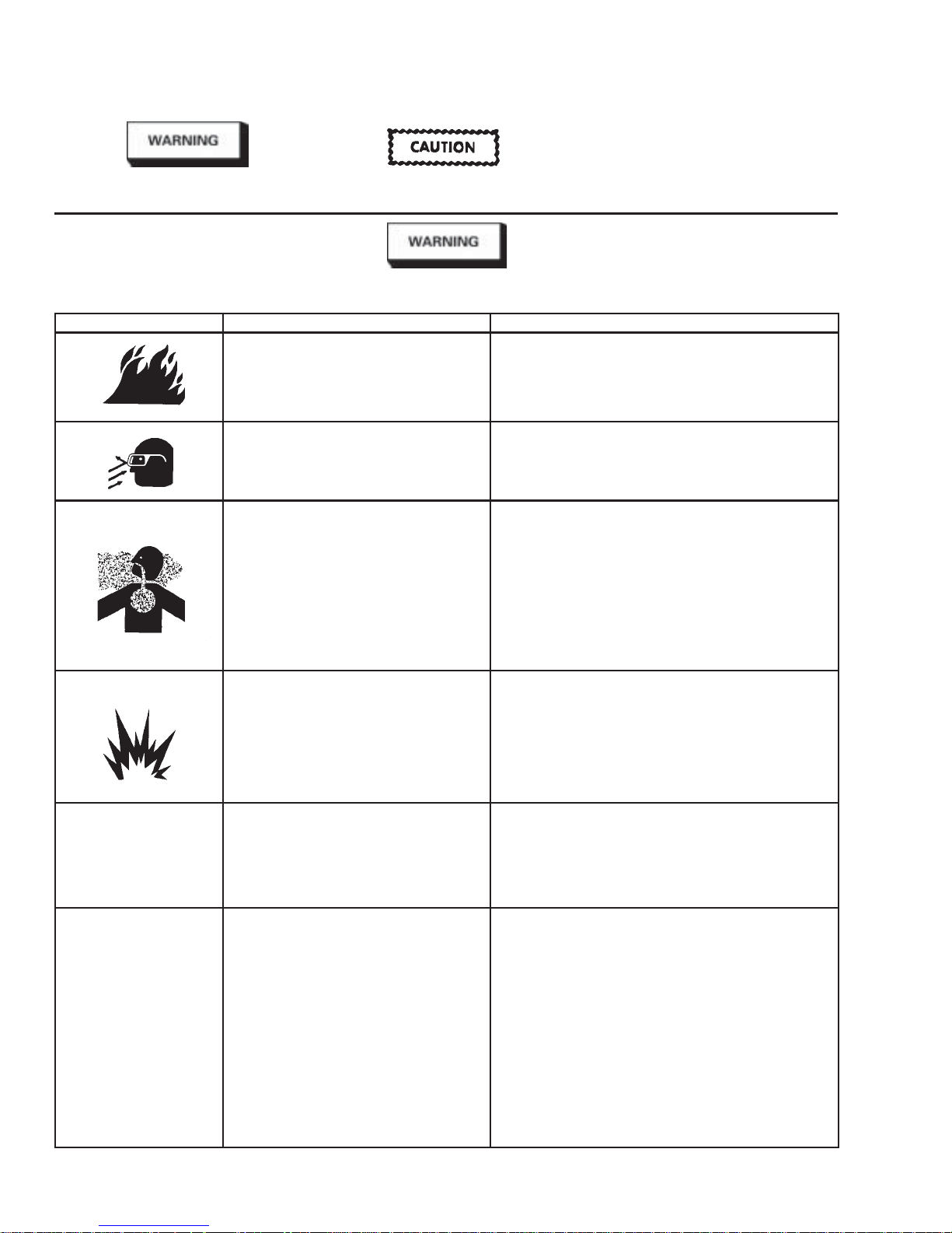
HAZARD CAUSE SAFEGUARD
Fire Solvent and coatings can be highly flammable Adequate exhaust must be provided to keep
or combustible, especially when sprayed. air free of accumulations of flammable vapors.
Solvent Spray During cleaning and flushing, solvents can be Wear eye protection.
forcefully expelled from fluid and air passages.
Some solvents can cause eye injury.
Inhaling Toxic Certain materials may be harmful if inhaled, Follow the requirements of the Material Safety Data Sheet
Substances or if there is contact with skin. supplied by your coating material manufacturer.
Explosion Hazard - Halogenated hydrocarbon solvents - for Guns with stainless steel internal passageways may be used
Incompatible Materials example; methylene chloride and 1, 1, 1 - with these solvents. However, aluminum is widely used
Trichloroethane can chemically react with in other spray application equipment - such as material
aluminum. The chemical reaction caused by pumps, regulators, valves & cups. Check all equipment items
these solvents reacting with aluminum can before use and make sure they can also be used safely
become violent and lead to an equipment with these solvents. Read the label or data sheet for the
explosion. material you intend to spray. If in doubt as to whether or not
General Safety Improper operation or maintenance Operators should be given adequate training in the safe use &
of equipment. maintenance of the equipment (in accordance with the
Cumulative Trauma Use of hand tools may cause cumulative Pain, tingling, or numbness in the shoulder, forearm, wrist,
Disorders “CTD’s” trauma disorders “CTD’s”. hands or fingers, especially during the night, may be early
CTD’s, or musculoskeletal CTD’s, when using hand tools, tend to affect the early symptoms may include vague discomfort in the hand,
disorders, involve damage upper extremities. Factors which may increase loss of manual dexterity, and nonspecific pain in the arm.
to the hands, wrists, elbows, the risk of developing a CTD include: Ignoring early symptoms and continued repetitive use of the
shoulders, neck and back. arm, wrist and hand can lead to serious disability. Risk is
Carpal tunnel syndrome and 1. High frequency of the activity. reduced by avoiding or lessening factors 1-7.
tendinitis (such as tennis 2. Excessive force, such as gripping, pinching
elbow or rotator cuff or pressing with the hands and fingers.
syndrome) are examples 3. Extreme or awkward finger, wrist, or arm
of CTD’s positions.
4. Excessive duration of activity.
5. Tool vibration.
6. Repeated pressure on a body part.
7. Working in cold temperatures.
Important information that tells how to
prevent damage to equipment.
Smoking must never be allowed in the spray area.
Fire extinguishing equipment must be present in the spray area.
Adequate exhaust must be provided to keep the air free of
accumulations of toxic materials.
Use a mask or respirator whenever there is a chance of inhaling
sprayed materials. The mask must be compatible with the
material being sprayed and its concentration. Equipment must
be as prescribed by an industrial hygienist or safety expert, and
be NIOSH approved.
a coating or cleaning material is compatible, contact your
material supplier.
requirements of NFPA-33, Chapter 15). Users must comply with
all local & national codes of practice and insurance company
requirements governing ventilation, fire precautions, operation,
maintenance and housekeeping. These are OSHA Sections
1910.94 and 1910.107 and NFPA-33.
symptoms of a CTD. Do not ignore them. Should you experi
ence any such symptoms, see a physician immediately. Other
Information that you should pay special attention to.
 Loading...