

Page 1
DeVILBISS
OXYGEN
CONCENTRATOR
DeVO/MC44-90
|
220
VOLT
50
Hz
SERVICE
-
We
add
1-800
Somerset,
Canada € France € Japan e U.
433-1331 e 814
PA
MANUAL
life
to
every
U.S.A.
breath.
443-4881
15501-0635
Kingdom e W.
Germany
SB-MC44
-220M
Page 2
TABLE
OF
CONTENTS
Section
Section 2 -
Section 3 -Installation
Section 4 -
Section 5 -
Section 6 -
Section 7 -
1-General
A.
B.
C.
D.
Theory
A.
B.
Maintenance
A.
B.
C.
Alarm
A.
B.
Information
Initial
Inspection
Maintaining
Warnings/Hazards
General
of
Operation
Installation
Operation
Testing
Routine
Periodic
System
Patient
Microcomputer
Troubleshooting
Service
A.
Instructions
Proper
Description
and
and Calibration
Maintenance
Maintenance
Alert
Repair
B.CabinetCovers.......................................
<.
Flow
Meter
D.
Pressure
E.
ManifoldlheckValves
F.
Molecular
G.
Four-Way
H.
Purge
|.
Compressor
J.
Pilot
К.
Manifold
L.
CapacitOr
M.CoolingFan..........................................
М.
Microcomputer
O.
Normal
Regulator
Valve
Pressure
Cycling
................................,......
.......................................
the
DeVO/MC44
............................
......................................
of
the
DeVO/MC44
...................
...............,.........,,......,.....
Operating
............................................
...............,.............................
Procedures
Procedures
.................................:.
......................
.................................
................................... 5 ㆍ
...................................
.........................
System
Control
Guide
....................................
Board
...........................
..................................
00
eee
............................,.........
Procedures
..........................................
.............................
...................................
................................
Sieve
Valve
Bed
Assemblies
......................................
........................
..........................................
..........................................
System
Assembly
een
Control
Sequence
..................................
...................................
Board
of
.........................
DeVO/MC44
...............
1
1
1
1
1
2
3
3
3
B
5
6
8
8
8
10
13
13
13
14
14
14
15
16
17
19
21
21
22
23
23
24
10/87
Section 8 -
Pneumatic
Electrical
Упк
Dealer
Block
бресИсаНоп$
Warranty
Parts
List
Diagram
Diagram
and
Wlustrations
................................
......................
for
Model
MC44
...............
0...
eee
............................
eee
K 0
K
25
38
39
40
41
Page 3
SECTION
1
GENERAL
A.
Initial
Inspection
An
Initial
inspection
DeVO/MC44
After
unpacking
any
external
during
the
DeVilbiss
dealer
The
for
concentrator
operated
Section 3 of
operate
contact
or
your
B.
Maintaining
The
DeVO/MC44
cording
the
manual.
is
required
qualified
maintain
C.
Warnings/Hazards
Oxygen
When
Person
Near
Hot,
Electrical
Removed
as
soon
damage
shipment.
international
specific
for
at
this
properly
the
DeVilbiss
dealer.
the
to
the
guidelines
Whenever
it
should
service
the
unit
Promotes
Using
The
Receiving
Sparking,
Shock
Hazard:
By A Qualified
INFORMATION
should
the
concentrator,
!f
damage
instructions.
should
least 30
manual.
or
DeVO/MC44
should
personnel.
may
Warning
Rapid
DeVO/MC44
Oxygen
Or
Warning
be
performed
as
possible
that
may
have
has
occurred,
Department
then
be
turned
minutes
internal
If
the
damage
as
International
be
routinely
set
forth
routine
be
servicing
performed
Failure
void
the
warranty.
Burning.
Therapy.
Burning
The
DeVilbiss
Do
Or
When
Objects.
Cabinet
Dealer.
on
after
receipt.
examine
occurred
contact
or
on
outlined
unit
fails
is
found
Department
serviced
in
Section 4 of
or
repair
by
to
properly
Not
Smoke
Near
Do
Not
May
Only
it
your
only
the
for
and
in
to
ac-
A
Use
Be
directs
ing
a
very
tively
concentration
Because
beds,
depressurize
allows
of
the
air
into
molecular
synthetically
porous,
sieve
produced
and
adsorbing
of
the
DeVO/MC44
it
is
able
the
the
unit
adsorbed
nitrogen
to
producing a high
process
approximately
altitude
assures
is
alternated
and
oxygen
the
patient
every
oxygen.
The
oxygen
leaving
through a check
From
here
it
passes
flow
meter,
filter
before
meter
and
adjusted
patient's
Тре
DeVO/MC44
visible
diagnostic
personnel.
power
or
pneumatic
and a second
exiting
allows
the
physician.
patient
service
This
failure,
component
to
alert
alert
low
one
of
two
cylinders
material.
This
inorganic
has
the
unique
nitrogen.
oxygen
to
other
cleanse
This
for
the
has
two
pressurize
bed
at
the
the
depressurized
while
the
pressurized
concentration
between
16
seconds
output
flow
of a continuous
the
sieve
valve
to
an
accumulator
through a pressure
high
efficiency
at
the
outlet
oxygen
the
incorporates
system
system
flow
level
system
to
system
pressure,
prescribed
as
be
will
failure.
contain-
sieve
material
silicate.
quality
of
is
It
is
selec-
produces a high
patient.
molecular
one
same
bed
time.
sieve
and
This
bed
bed
is
of
oxygen.
the
depending
rate.
The
beds
is
two
beds
cycling
supply
directed
This
on
of
tank.
regulator,
bacteria
fitting.
to
an
well
used
activate
The
be
controlled
audible
as a self-
by
and
electrical
flow
by
the
and
service
due
to
D.
General
The
DeVilbiss
is
designed
oxygen
in
the
providing
2,92%
4
liters
minute.
similar
Room
oxygen
DeVO/MC44
Description
to
for
the
home
95% + 3%
+
3%
at 3 liters
per
minute,
This
is
to
filtration.
air,
which
and
78%
by a compressor.
DeVO/MC44
through a gross
a
high
efficiency
the
compressor.
will
produce
flow
from a cooling
Leaving
HEPA
filter
clean
the
compressor,
and a four-way
of
deliver
patient
or
high
requiring
institution.
oxygen
per
and
70% + 3%
accomplished
contains
nitrogen,
particle
filter, a felt
bacteria
The
“WOB’L”
oil
free
fan.
the
the
DeVO/MC44
Oxygen
Concentrator
concentrations
oxygen
It
is
capable
concentration
minute,
approximately
80% + 3%
at S liters
by
using a process
is
drawn
The
pre-filter,
filter
before
type
compressor
air
and
is
cooled
air
passes
directional
therapy
at
21%
into
air
passes
entering
by
through
valve
of
of
1-
at
per
the
and
air
a
that
10/87
Page 4
SECTION
THEORY
The
similar
2
microcomputer
to
the
DeVO/44
OF
OPERATION
controlled
and
MC29
in
uses a pressure-depressurization
produces
efficient
are
DeVO/44
Observation
cycle
in
conjunction
the
trouble-shooting
observed
points
Variations
can
de-activating
complete
This
dependent
cycle
monitored
control board).
a
pressure
ducer
1/16”
oxygen
A
cycle
pressure
25.5
the
received
and
air
way
high
manner.
also
pneumatically
and
is
one
MC
board,
by
located
in
be
observed
cycle
is
an
approximate
and
the
transducer
is
connected
(1.6
mm)
pressure
change
in
the
PSI
(176
four-way
by
purge.
from
the
and
purge
concentrations
The
four-way
of
and
operated
MC29.
of
the
pressure-depressurization
way
to
isolate
with
the
it
can
the
installing a set
on
the
the
pressure-depressurization
in
relation
of
the
four-way
takes
on
the
liter
alarm
by
the
MC
This
is
to
diameter
in
the
takes
accumulator
KPa).
At
and
purge
pilot
valves
These
pilot
pilot
accumulator
so
they
problems.
indicator
be
of
significant
unit.
Cycle
of
gauges
manifold.
to
the
and
approximately
time
because
flow
and
system
are
board
accomplished
on
the
MC
the
accumulator
hose.
It
accumulator.
place
tank
this
point a signal
valves.
located
valves
allow
to
can
be
activated.
oxygen
lights
operation
(microcomputer
board.
constantly
only
is
on
DeVO/MC44
many
ways.
system
which
in a very
purge
similar
When
valves
to
used
located
help
when
can
to
the
cycle
activating
purge
valves.
22
seconds.
all
cycles
altitude.
controlled
by
the
use
The
trans-
tank
senses
when
approximately
is
sent
This
signal
the
four-way
compressed
enter
the
four-
is
It
the
on
be
test
and
A
are
The
and
of
by
a
the
to
is
which
the
the
purge
and
the
is
bed.
four-way
pressed
bottom.
allows
bed
from
bed
being
The
valve.
air
is
At
the
high
the
to
start
exhausted
air
and
When
directed
top.
concentrations.
air
in
the
previously
This
exhaust
can
closes.
At
the
beginning
needie
on
the
approximately
the
purge
needle
rise
until
maximum
four-way
drop
KPa).
and
bed.
hesitate
steadily
KPa).
continuous
to
depressurized
orifice.
reached,
anew
opening.
will
hesitate
maximum
accumulator
shifts
in
pressure
This
drop
releasing
When
the
slightly
and
This
low
flow
When
the
cycle
begins.
some
level
maximum
four-way
being
exhausted
out
of
the
into
same
time,
purity
When
This
its
cycle
oxygen
additional
the
pressurized
be
heard
of
the
gauge
15
PSI
will
(103
When
slightly
pressure
and
the
to
approximately
is
caused
of
purge
and
off
at
pressure
of
oxygen
bed
and
through
the
four-way
the
the
the
passes
exhaust
other
purge
to
enter
bottom
through
port
shifts,
bed
from
valve
the
pressure
at
higher
purge
each
pressurization
suddenly
KPa).
the
and
pressure
gauge
by
the
oxygen
closes,
then
pressures
valve
bed
is
exhausted.
time
increase
This
is
purge
then
continue
is
reached.
is
reached,
will
show a sudden
15
the
purge
to
the
needle
continue
closes,
the
cycle
caused
closes,
PSI
opening
the
to
approximately 2 PSI
reading
through
accumulator
from
purge
is
caused
the
pressurized
the
pressure
valves
manifold
shift
of
of
the
com-
the
opens
same
allows
and
the
purge
the
to
by
the
to
When
the
(103
other
will
drop
(13.8
by
the
is
and
The
four-way
position
PSI
tank.
this
activated
that
until
(175.8
This
takes
pressure
causing
when
KPa)
activated,
pressurization
activated,
Although
time
activated
It
is
during
the
pressurized
bed
that
During
from
into
located
purge
10/87
the
the
as
the
four-way,
position
this
is
just
pressurization a small
the
pressurized
the
depressurized
in
the
the
nitrogen
valve
will
the
right
of
oxygen
approximately
is
reached
the
left
of
the
right
left
bed
purge
valve
for
approximately
time
that
bed
is
allowed
beginning
bed
manifold.
from
remain
sieve
bed
the
is
is
it
high
in
bed
in
the
11
the
four-way
to
pressurize.
four-way
sieve
bed.
being
activated
only
remains
purity
to
its
pressurization
amount
is
constantly
bed
through
This
oxygen
the
depressurized
the
activated
builds
up
accumulator
seconds.
When
is
allows
When
pressurized.
at
the
same
in
1.0
seconds.
oxygen
flow
into
cycle.
of
oxygen
flowing
the
orifice
flow
helps
25.5
de-
Note
de-
this
from
the
bed
Page 5
SECTION
3
INSTALLATION
A.
Installation
1.
B.
Operation
1.
Position
control
lt
cycle,
a
minimum
of
trator
radiators,
NOTE:
imprinted
2)
read:
WARNING:
burning.
DeVO/MC44
receiving
near
Electrical
cabinet.
removed
With
position,
volt,
handling a minimum
Push
"ON"
illuminate,
cated
of
switch
is
guide
When
audible
the
erable
may
the
surize.
continues
shooting
The
"Service
illuminate
remain
system
With
turn
(S
the
panel
must
be
electrical
other
appliances.
should
Always
located
hot,
the
50
cycle,
the
position.
in
the
the
unit.
still
unbroken,
for
the
alarm
unit
length
sound
accumulator
If
visible
on
is
the
the
knob
Fig.
2)
AND
concentrator
is
convenient
accessible
outlet
of 7 amps
not
be
heaters,
or
observe
on
the
instruction
on
the
front
Oxygen
Do
not
smoke
or
when
oxygen
sparking,
shock
The
therapy.
or
hazard:
cabinet
by a qualified
power
plug
the
switch
line
electrical
On/Off
check
power
switch
If
the
the
connector
Replace
fails
to
illuminate,
refer
to
specific
power
has
instructions.
switch
will
sound
not
been
of
time,
for
an
extended
has
the
alarm
to
sound
guide
for
specific
alarm
on
the
Required”
when
the
until
pressure
approximately 9 PSI.
DeVO/MC44
(6
Fig.
until
the
such
to
to a 240
capable
that
is
independent
The
oxygen
located
hot
air
registers.
the
label
of
the
promotes
when
near a person
Do
burning
Do
not
may
DeVilbiss
in
cord
outlet
of 7 amps.
(1
Fig.
switch
fuse
(1
if
necessary.
and
the
troubleshooting
is
turned
momentarily.
used
for a consid-
the
audible
had
time
does
not
refer
to
the
instructions.
control
(2
Fig.
unit
is
turned
operating,
2)
on
the
ball
in
the
OPERATING
that
the
the
patient.
volt,
50
of
handling
concen-
adjacent
warnings
unit.
using
objects.
only
the
into a 240
capable
2)
does
Fig.
on
period
sound
panel
2).
within
flow
to
(4
Fig.
They
rapid
the
not
use
remove
be
dealer.
“OFF”
of
to
the
not
4)
lo-
the
back
If
the
the
fuse
on,
the
alarm
until
to
pres-
or
trouble-
says
It
will
on
and
the
slowly
meter
meter
If
is
PROCEDURES
centered
-
the
Flow
LPM.
positioned
enclosed
properly
tions
Therefore,
retained
log
Important:
pletely
tubing
because
When
trator
extended
up
oxygen
flow
period
and
If a humidifier
the
delivery
the
not
If a humidifier
a
bubble-type
humidifier
the
to
the
NOTE:
DeVO/MC44
pressure
“Set-Type”
properly
bubble-type
Included
plastic
piece
Fig.
8
inches
fitting
(203
fitting
humidifier
tightened
fitting.
oxygen
mm)
may
from
on
the
prescribed
meter
accuracy
Because
as
with
the
may
not
this
or
the
book
for
future
If
off
it
alarm”
of
the
the
DeVO/MC44
is
turned
period
to
30
minutes
concentration
rate
may
of
time
readjusted
physician,
tubing
oxygen
exceed
elastic
outlet
50
stand
strap
stand.
For
optimum
has a pre-set
of
8.5
humidifiers
at
humidifiers
with
fittings
of
tubing.
8)
for
all
humidifiers
(203
(3
Fig.
mm)
and
by
turning
counterclockwise
securely
Connect
outlet
piece
of
have
to
kinking.
line
corresponding
flow
rate.
will
of
this,
the
shown
every
correct
unit.
be
attained
green
on
oxygen
information
reference.
flow
meter
may
activate
and
turn
severely
on
(or
if
of
time),
for
the
drift
slightly
and
should
if
necessary.
has
not
been
the
5/32”
can
be
attached
fitting.
feet
(15
m).
has
been
humidifier
(4
Fig.
(5
Fig.
performance,
PSI
(58.6
this
low
the
DeVO/MC44
and a 3-inch
Use
the
mm)
tall
8)
for
humidifiers 8 inches
taller.
Attach
the
on
the
humidifier
fitting
tubing
be
with
(4
shortened
vary
slightly
ball
should
the
green
If
ball
is
concentra-
at 5 LPM.
card
should
recorded
is
turned
the
“crimped
the
unit
restricted
flow.
oxygen
not
in
use
it
may
flow
rate
to
stabilize.
during
be
monitored
prescribed
(4
mm)
directly
Tubing
prescribed,
(6
Fig.
3)
3)
securing
3)
that
is
attached
nominal
KPa),
therefore,
will
not
function
pressure.
should
straight
that
and
be
(76.2
are
the
fitting
less
the
wing
nut
until
the
humidifier
the
3-inch
Fig.
8).
The
to
prevent
with
at
5
be
card
not
set
be
in
a
com-
off
concen-
for
an
require
and
The
this
by
1.D.
to
should
place
on the
it
with
the
output
Only
used.
are
mm)
(2
than
elbow
proper
on
the
it is
to
the
(76.2
tubing
2
it
10/87
Page 6
SECTION
3
INSTALLATION
Attach
I.D.
the
cannula
not
Condensation
occur
the
oxygen
humidifier
or a suitable
exceed
in
longer
desired
delivery
50
feet
from
lengths
length
tubing
and
attach
mask.
(15 m).
the
AND
of
5/32”
(7
Fig.
either
Tubing
humidifier
of
tubing
OPERATING
(4
mm)
3)
to
a
should
may
or
with
PROCEDURES
tubing
reduced
ifier
end
outlet
plastic
The
may
laying
by
stand.
of
the
delivery
fitting
fitting
DeVO/MC44
now
be
on a cold
using
To
use
and
on
the
used.
floor.
the
removable
the
stand,
tubing
the
humidifier.
oxygen
to
other
This
can
humid-
attach
the
end
concentrator
one
oxygen
to
the
be
10/87
Page 7
SECTION
4
MAINTENANCE
Every
"burned-in“
of
assure
ous
formed
dealer.
are
A.
DeVO/MC44
the
product
continued
maintenance
on a regular
The
provided
Testing
1.
Turn
tion
trol
rate
minute.
When
used
may
gen
rate
of
gradually
specific
When
stabilized,
attached
Fig.
various
should
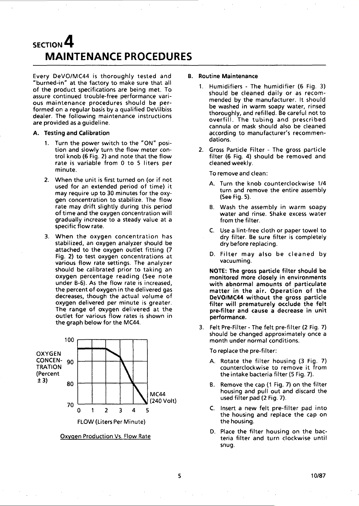
oxygen
under
the
decreases,
oxygen
The
outlet
the
OXYGEN
CONCEN-
TRATION
(Percent
+3)
at
the
factory
specifications
trouble-free
procedures
following
as a guideline.
and
Calibration
the
power
and
slowly
knob
(6
Fig.
is
variable
the
unit
for
an
require
concentration
may
drift
time
and
the
increase
flow
the
oxygen
an
to
2)
to
test
flow
be
calibrated
percentage
B-6).
As
percent
range
graph
100
90
80
70
Oxygen
of
though
delivered
of
for
various
below
ο
FLOW
Production
is
thoroughly
to
basis
by a qualified
maintenance
switch
turn
2)
and
from 0 to 5 liters
is
first
extended
up
to
30
to
slightly
oxygen
to a steady
rate.
oxygen
the
oxygen
oxygen
rate
settings.
the
flow
oxygen
the
per
oxygen
flow
for
the
1
2
(Liters
PROCEDURES
tested
make
sure
are
being
performance
should
instructions
to
the
“ON”
the
flow
meter
note
that
turned
minutes
stabilize.
concentration
analyzer
prior
reading
in
Per
Vs.
on
period
during
concentration
concentrations
actual
minute
delivered
3
of
for
outlet
The
to
rate
is
the
delivered
rates
is
MC44.
4
Minute)
Flow
Rate
this
volume
and
that
met.
To
vari-
be
per-
DeVilbiss
posi-
con-
the
flow
per
(or
if
not
time)
the
oxy-
The
flow
period
will
value
at
has
should
fitting
analyzer
taking
(See
note
increased,
gas
is
greater.
at
the
shown
MC44
(240
Volt)
5
all
it
a
be
(7
at
an
of
in
B.
Routine
1.
Maintenance
Humidifiers - The
should
mended
be
thoroughly,
overfill.
cannula
according
dations.
Gross
filter
cleaned
To
A.
B.
C.
D.
NOTE:
monitored
with
matter
DeVO/MC44
filter
pre-filter
performance.
Felt
should
month
To
A.
B.
C.
D.
be
by
washed
or
Particle
(6
Fig.
weekly.
remove
Turn
turn
and
(See
Fig.
Wash
water
from
the
Use a lint-free
dry
filter.
dry
before
Filter
vacuuming.
The
abnormal
in
will
Pre-Filter - The
be
under
replace
Rotate
counterclockwise
the
intake
Remove
housing
used
filter
Insert a new
the
housing
the
housing.
Place
teria
snug.
humidifier
cleaned
the
manufacturer.
in
warm
and
refilled.
The
tubing
mask
should
to
manufacturer's
Filter - The
4)
should
and
clean:
the
knob
counterclockwise
remove
5).
the
assembly
and
rinse.
filter.
cloth
Be
sure
replacing.
may
also
gross
particle
more
closely
amounts
the
air.
without
prematurely
and
cause a decrease
felt
changed
the
the
the
and
the
filter
approximately
normal
pre-filter:
filter
bacteria
cap
(1
pull
pad
(2
felt
and
filter
housing
and
daily
turn
or
soapy
Fig.
water,
Be
careful
and
prescribed
also
gross
be
removed
the
entire
in
warm
Shake
Operation
conditions.
out
replace
excess
or
paper
filter
is
be
cleaned
filter
in
environments
of
the
gross
occlude
pre-filter
housing
to
remove
filter
(5
Fig.
7)
on
and
7).
pre-filter
on
clockwise
(6
Fig.
3)
as
recom-
It
should
rinsed
not
to
be
cleaned
recommen-
particle
and
1/4
assembly
soapy
water
towel
to
completely
by
should
particulate
(3
Fig.
discard
the
be
of
the
particle
the
felt
in
unit
(2
Fig.
once
Fig.
it
from
7).
the
filter
the
pad
into
cap
on
the
bac-
until
7)
7)
a
10/87
Page 8
SECTION
4
MAINTENANCE
С.
Intake
filter
same
and
mately
To
A.
B.
D.
Audible
system should
maintenance
checked
A.
B.
NOTE:
purchased
batteries
02
tions
accordance
procedures
NOTE:
the
calibrated
source.
changes
midity
tration
Therefore,
calibrated
the
Periodic
Bacteria
(5
time
changed
every
replace
Pull
rubber
Remove
Place
new
The
be
inserted
To
test
remove
volt
switch
alarm
replace
located
divider.
Plug
and
“ON”
momentarily.
or
sounds
battery.
Concentrations - Oxygen
should
Before
oxygen
reading
concentrator
Maintenance
Filter - The
Fig.
6)
should
the
felt
when
six
the
intake
the
bacteria
grommet
the
the
feit
bacteria
complete
into
be
pre-filter
months).
bacteria
(See
felt
pre-filter
pre-filter
filter.
filter
the
Alarm - Testing
be
included
program.
on a monthly
the
the
AC
outlet
to
the
is
not
the 9 volt
on
the
the
unit
turn
the
position.
weak
basis.
audible
line
cord
and
“ON”
heard
front
into a 220
power
The
If
the
replace
Replacement
locally
or
(Section
and
equivalent.
be
checked
with
the
4,
A).
checking
analyzer
should
using a 100%
It
should
in
temperature,
may
affect
the
in
similar
also
the
as
shown
analyzer
conditions
is
located.
PROCEDURES
intake
inspected
needed
filter
Fig.
assembly
rubber
the
alarm
turn
position.
or
battery
of
switch
alarm
alarm
batteries
should
established
concentrations,
be
altitude,
oxygen
by
bacteria
at
the
is
inspected
(approxi-
filter:
out
of
the
6).
assembly.
assembly
can
on
then
grommet.
audible
alarm
in a routine
!t
should
system,
from
the
220
the
power
if
sounds
volt
(20
the
will
is
not
weak,
Fig.
vertical
AC
outlet
to
sound
heard
the
the 9 voit
can
be
alkaline
concentra-
monthly
test
be
properly
pure
oxygen
noted
that
or
concen-
the
analyzer.
should
to
where
the
hu-
a
be
11)
be
in
be
Final
Bacteria
filter
(3
Fig.
needed
normal
To
A.
C.
D.
E.
(approximately
conditions).
replace
Loosen
top
Swing
the
and
the
Remove
each
end
Install
with
new
hose
Replace
fasteners.
Compressor
filter
(12
Fig.
before
To
A.
25,000
replace
Refer
to
compressor
cabinet
be
completely
B.
Cut
plastic
filter
in
C.
Loosen
rubber
D.
Install
new
directional
and
secure
NOTE:
directly
screws
unit
can
E.
F.
Holes
behind
and
must
be
inserted
Attach
of
filter
Replace
with
cabinet
Compressor
necessary
10,000
See
NOTE:
hour
Service
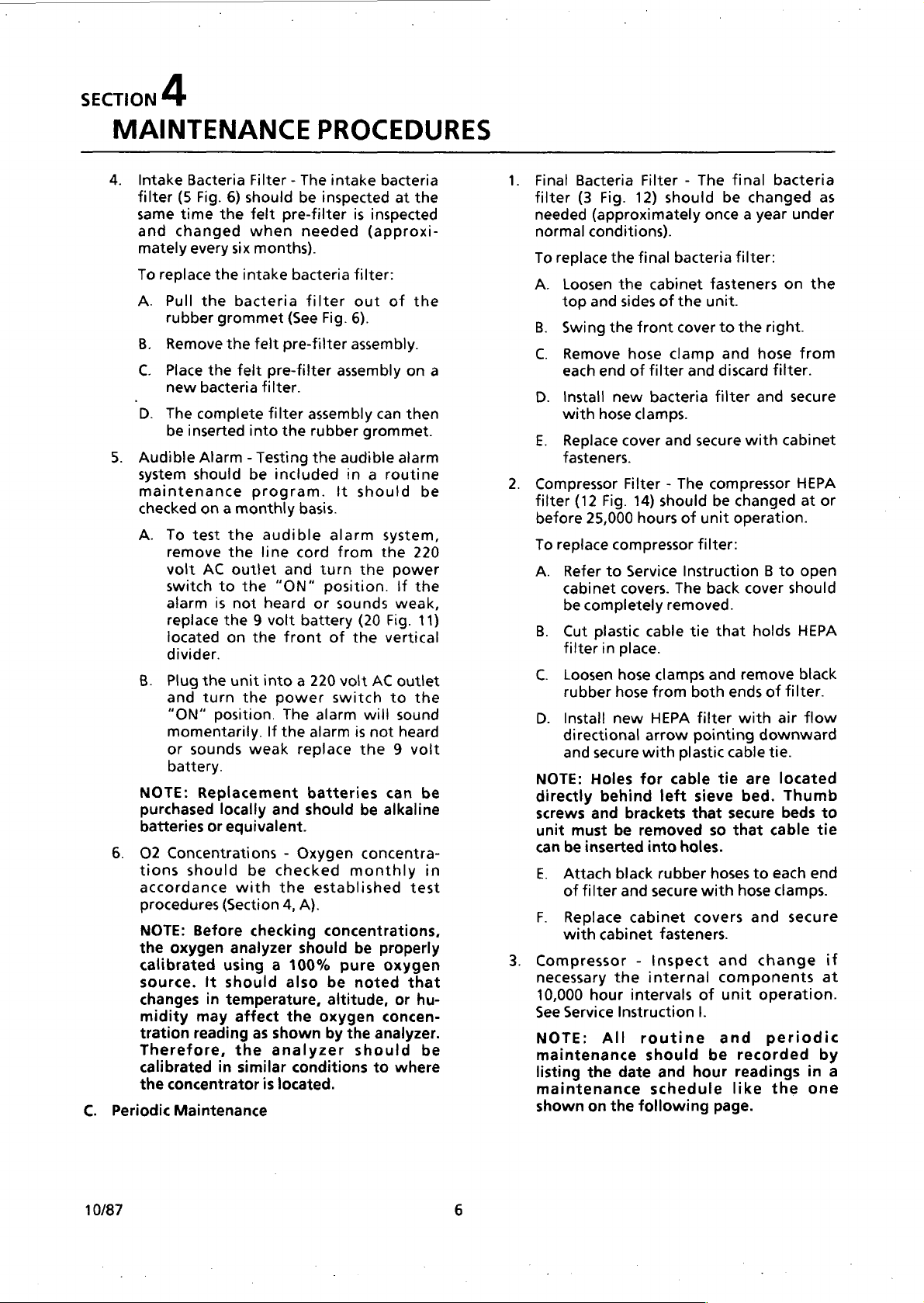
All
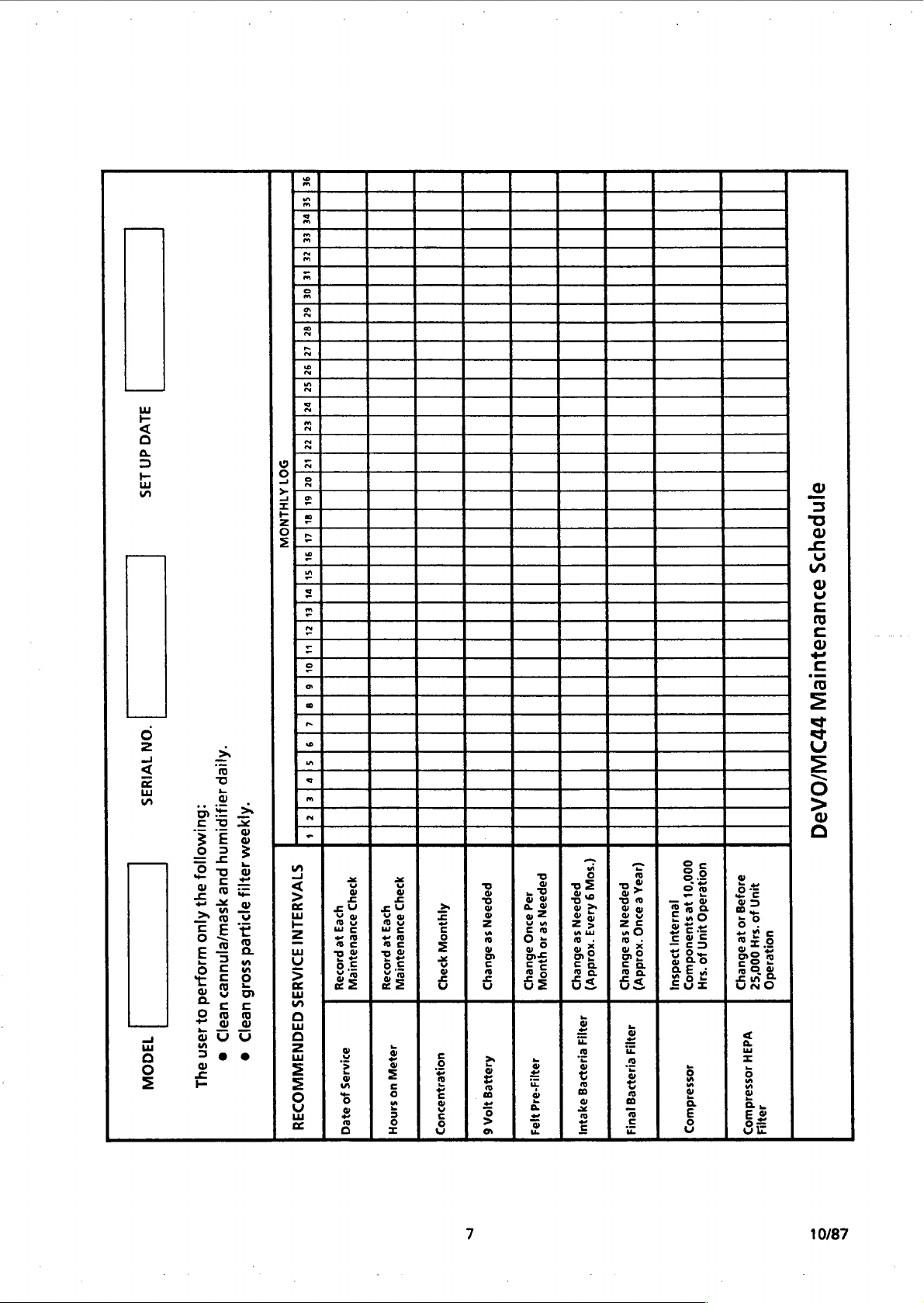
maintenance
listing
the
maintenance
shown
on
the
Filter - The
12)
should
final
bacteria
the
cabinet
sides
of
the
front
cover
hose
clamp
of
filter
and
bacteria
clamps.
cover
and
Filter - The
14)
should
hours
of
Service
covers.
place.
hose
hose
Instruction B to
The
removed.
cable
tie
clamps
from
HEPA
arrow
with
plastic
for
cable
left
brackets
be
removed
into
holes.
black
rubber
and
secure
cabinet
fasteners.
-
Inspect
the
internal
intervals
Instruction
routine
should
date
and
schedule
following
final
be
changed
once a year
filter:
fasteners
unit.
to
the
and
discard
filter
secure
with
compressor
be
changed
unit
operation.
filter:
back
cover
that
holds
and
remove
both
ends
filter
with
pointing
cable
tie
are
sieve
bed.
that
secure
so
that
hoses
to
with
hose
covers
and
and
components
of
unit
|.
and
be
recorded
hour
readings
like
page.
bacteria
as
under
on
the
right.
hose
from
filter.
and
secure
cabinet
HEPA
at
or
open
should
HEPA
black
of
filter.
air
flow
downward
tie.
located
Thumb
beds
to
cable
tie
each
end
clamps.
secure
change
if
at
operation.
periodic
by
in
the
one
a
10/87
Page 9
alvd
dN
Las
"ON
1VIH
ヨ
S
“Ajlep
saipipluiny
“Apşaom
:6ulAAollol
velez|zz[izjoz|orfe
DO1A1HLNOW
le
[om]
sifurjer
za
oesforf
ee
|<]
op
spofe[z]o
ajnpayrs
SOuEu91UIBI
tt)W/OA2Q
14dOW
191J14
pue
ad
ysew/ejnuued
히
Ájuo
2!11004
wu1ojiad
55016
ues|>
46
03
히
49sn
2
@
e
au
SIVAUIINI
IDIAYIS
CIONIINNODIY
1934)
We3
4263
MULUIJUICIA
je
provou
BAJOS
40
8γεα
yay)
Ayu
as2ueuajurew
je
P1030Y
1933
YO
SANOH
uo
19340
4011613403403
papaan
og
8240
se
aBueuy
abuey>
Aisyeg
184-214
HOA
193
6
(SOW
papaan
9
A1313
se
‘xo1ddy)
abuey>
13Y14
211989
9yeyul
(ea,
papaan
e
au
se
‘xoiddy)
abuey)
19414
Cuapeg
[EU
000'01
uone1ado
¡euJa3u]
3e
$3
UUN
иэцодшо5
padsul
JO
'SIH
』Ossa』duuO
う
310498
HUN
40
10
“SAH
uone1ado
ye
95ueu
000'SZ
う
Vd3H
10sso1dw03
seua
10/87
Page 10
SECTION
5
ALARM
Most
problems
MC44
This
audible
there
problems
the
personnel
The
the
A.
are
indicated
system
is
alarms
comprised
which
is a malfunction.
are
indicated
MC
board.
These
troubleshoot
alarm
MC
Patient
1.
system
board.
Alert
Visible
located
Alarm
on
Required”
illuminated
such
as
low
compressor
flow
will
illuminate. A more
of
the
type
observing
the
MC
board.
NOTE:
come
turned
period,
The
on
on.
or
operating,
2.
guide
Audible
will
in
Section
Alarm
sound
pressure,
component
alarm
system.
the
unit
accumulator
powered
is
The
alarm
of
the
MC
alarm
control
B.
Microcomputer
The
board
cover
monitoring
as
well
transducer
When
indicates a malfunction,
be
activated
transmits
panel
microcomputer
(7
Fig.
of
the
and
as
the
(13
the
pressure
component
activated
if
the
SYSTEM
encountered
by
the
alert
by
are
problems
is
monitored
System
System - The
the
control
(2
Fig.
it
indicates a unit
pressure,
failure. A severe
also
of
problem
the
alarm
“Service
momentarily
If it
stays
comes
refer
to
6.
System - The
when
power,
failure
This
is
turned
has
had
by a 9
itself
is
board.
(3
Fig.
Control
12)
is
located
unit.
controlling
alarms
Fig.
12).
sensed
whether
failure.
system
with
patient
of
both
the
Further
alarm
lights
designed
and
panel
2).
When
valve,
cause
definitive
can
indicator
Required”
when
on
for
on
while
the
troubleshooting
there
is a low
valve,
that
alarm
will
time
volt
alkaline
located
When
the
sound
2).
Board
contro!
on
It is
responsible
the
by
using a pressure
by
the
alarm
it
is
for a pressure
Alarms
fails
to
within
this
on until
to
on
the
DeVO/
alert
system.
visible
patient
when
isolation
located
to
help
service
the
activated
visible
says
this
alarm
“Service
panel
malfunction
sieve
bed,
restriction
panel
description
be
found
lights
panel
the
unit
an
extended
the
unit
audible
or
or
other
activates
sound
pressurize.
battery.
the
backside
activated
through
board
the
this
will
operate
or
inside
entire
system
transducer
system
also
within
and
of
on
unit.
by
is
or
of
to
by
on
will
is
is
alarm
high
the
when
the
It
the
the
MC
front
for
will
or
be
the
pre-set
times.
The
DeVO/MC44
system
disconnected
the
patient
malfunction
is
still
malfunctions
minimum
cannot
or
from
because
operational.
will
automatically,
damage
The
Fig.
cycle
what
unit.
shooting
information
pressure
22)
sequence
When
indicator
sequence.
illuminate
cases,
further
the
may
malfunction.
light
causes
1.
to
the
MC
board
12)
labeled
and
high
type
of
They
aid
test
on
the
manifold.
on
a
malfunction
lights
One
when
whether
testing
exact
cause
be
more
is
given
for
the
Short
Cycle:
beds
have
minimum
been
pre-set
beds
pressurize
minimum
will
be
activated.
Possible
nation
and
will
activate
four-way
flow
may
malfunction
should
that
gauges
page
An
malfunction.
and
cycle
Cause: Severe
valve
on.
NOTE:
come
four-way
done
problem.
The
On
together
failure.
to
determine
Refer
Section 7 for
dures
for
the
and
maximum
is
designed
be
overridden.
weak
battery
being
the
For
will
alerted
visible
Also,
cause
the
unit
thus
preventing
unit.
has
four
red
indicator
short
cycle,
pressure.
be
in
conjunction
can
be
to
Refer
24.
long
These
has
occurred
used
derived
the
test
to
occurs
will
or
one
must
of
than
come
possibly
the
or
be
the
one
on
unit
shuts
two
done
problem
possible
two
lights
explanation
below
This
along
light
indicates
pressurized
maximum
on
the
time
so
MC
board.
quickly
is
reached,
cycle
cause a decreased
this
alarm. A failure
or a severe
also
cause
this
alarm
short
and
no
cycle
whether
Further
to
the
sieve
proper
beds
the
exact
Service
and
testing
cycle
so
its
alarm
example,
not
prevent
a
to a system
alarm
most
lights
to
any
cycle,
shut
system
major
off
further
lights
(8
no
indicate
in
the
as a trouble-
with
by
points
normal!
these
the
attaching
(Fig.
cycling
alarm
in a certain
lights
off.
to
determine
since
cause
of
each
with
will
In
come
on,
there
for
alarm
possible
all
the sieve
too
soon.
time
If
the sieve
that
this
bed
contami-
cycle
restriction
to
lights
it
is a bed
cause
alarm
time
of
come
must
of
A
has
the
the
of
will
or
be
the
Instructions,
testing
proce-
four-way.
a
10/87
Page 11
SECTION
5
ALARM
2.
Long
cycle
cycle
activated.
Possible
or
any
pre-set
NOTE:
by
itself
has
come
when a high
the
determine
problem.
Instructions,
testing
purge
on.
No
Cycle:
the
Possible
way
faulty
defective
of
flow
activate
SYSTEM
Cycle:
time.
time
been
on
unit.
depending
See
four-way
valve,
wiring
This
When
is
reached,
Cause: A faulty
problem
cycle
time
The
long
when
the
exceeded.
with
pressure
Further
the
Refer
Section 7 for
procedures
number 4 below:
This
light
valve
Cause:
inadequate
from
MC
board. A severe
or
contaminated
this
alarm.
light
indicates a long
the
pre-set
this
alarm
compressor,
that
causes
to
be
cycle
the
exceeded.
light
will
maximum
However,
the
high
pressure
situation
testing
Defective
must
exact
for
on
to
valve
cause
to
the
the
the
compressor
which
indicates a failure
shift
alarms
High
properly.
or
sticking
pilot
to
MC
beds
maximum
will
be
leak,
maximum
come
on
cycle
time
it
will
light
exists
be
Service
Pressure.
pressure,
board,
restriction
may
done
of
the
proper
come
four-
also
in
to
or
of
or
audible
Required”
illuminate.
The
lights
“four-way.”
Purge:
come
activated
Four-Way:
come
activated.
sieve
off,
Important:
designations
(Short
Pressure)
the
Bed,
Pressure.
DeVilbiss
either
malfunctions
same
alarm
light
MC
board
(8
Fig.
This
on
only
(approximately
This
on
only
At
bed
is
the
left
bed
Cycle,
some
following
Purge/Compressor,
These
Models
case
they
way.
will
sound
on
the
also
has
12)
labeled
These
are
green
when
green
when
the
same
being
pressurized.
is
pressurizing.
Instead
explained
Long
Cycle,
DeVO/MC44's
alarm
were
MC29
refer
and
and
control
two
green
“purge”
not
alarm
indicator
the
purge
1.0
indicator
the
four-way
time
of
in
No
light
designations:
4-way,
used
and
to
the
should
be
the
"Service
panel
indictor
lights.
light
valve
seconds).
light
valve
the
right
When
the
alarm
this
section
Cycle,
DeVO/44.
same
may
on
used
High
have
High
type
will
and
will
is
will
is
it is
the
in
of
the
NOTE:
come
way
be
the
Instructions,
testing
sieve
High
pressure
Possible
the
MC
NOTE:
lights
pressure
Further
determine
problem.
instructions,
testing
When
come
automatically
will
The
on
together
or
bed
done
to
problem.
procedures
beds.
Pressure:
situation
Cause:
activated
board
or
The
will
come
situation
testing
procedures
any
of
on
continue
short
failure.
determine
sticking
high
Refer
and
no
cycle
whether
Further
the
Refer
Section 7 for
This
Purge
position
pressure
on
the
Section 7 for
the
the
shut
to
to
for
the
light
in
the
system.
valve
due
valve.
together
exists
must
exact
to
for
the
four
red
compressor
off
but
operate.
indicates a high
lights
will
it
is a four-
testing
exact
the
the
four-way
remained
to a defective
and
when a high
in
be
cause
the
the
purge
indicator
the
must
cause
Service
proper
long
cycle
the
unit.
done
of
Service
proper
valve.
lights
will
cooling
Also,
and
the
fan
the
of
in
to
10/87
Page 12
SECTION
6
TROUBLESHOOTING
4.
5.
o.
Visible | Audible | Compressor
Alarm
1.
OFF
2.
3.
ON
ON
OFF
OFF
Symptom
、
Alarm
ON
ON
ON
OFF
OFF
On
or
OFF
OFF
OFF
ON
ON
GUIDE
Off
Other
Symptoms
On/Ott
switch
illuminated | yo
On/Off
İN
utumına
Unit
warm
o
the
U
cannot
restarted
for
several | Low
minutes
Pulsating
air
noise
Excessive
noise
Line
not
[|
or
defective
Line
termina!
Defective
Blown
Defective
ted
Loose
Defective
Defective
Upper
disconnected
Compressor
a
Occluded
an
be
Restricted
passage
Defective
Defective
Felt
filters
Compressor
disconnected
Defective
mounts
Defective
Defective
Possible
cord
power
cord
fuse
Compressor
.
and
.
line
and/or
not
Problems
not
properly
at
receptacle
disconnected
block block
On/Off
in
power
MC
board
compressor
Capacitor
lower
overheated
filters
. : :
input
voltage
cooling
compressor
intake
in
place
intake
or
loose
compressor
cooling
installed | Insert
at
switch
connector
Wire
wiring
harness | Reconnect
due
to:
or
output
air
fan
bacteria
or
defective
hose
motor
fan
line
Check
fuse,
by
Circuit
other
receptacle
Reconnect
Replace
Replace
Replace
Tighten
Replace
Replace
Replace
Remove
Check
circuit
appliances
Replace
Replace
Check
necessary
Reconnect
Replace
Replace
Replace
Suggested
99
plug
in
cord
building
or
have
qualified
electrician.
may
be
appliances
may
line
switch
fuse
MC
board
or
attach
compressor
Capacitor
wiring
filters
obstruction
line
voltage,
independent
cooling
compressor
filters
hose
or
tighten
compressor
cooling
Remed
receptacle
circuit
fully
and
be
required.
cord
wire
harness
fan
replace
fan
breaker
wiring
loaded
another
at
terminal
use
alternate
of
other
motor
house
and
y
or
replace
checked
with
if
mounts
or
10/87
10
Page 13
SECTION
6
TROUBLESHOOTING
Visible | Audible | Compressor
Alarm
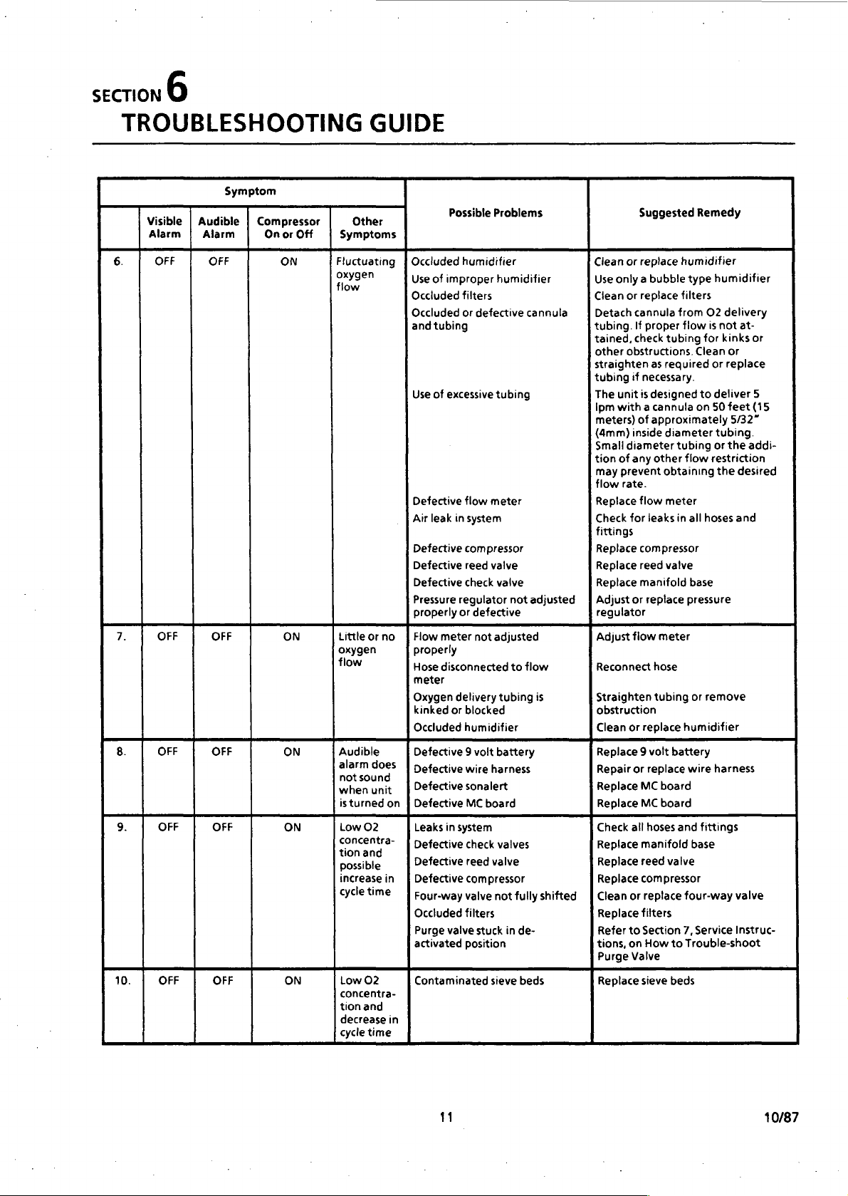
6.
8.
OFF
7.
9.
10.
OFF
OFF
OFF OFF
OFF OFF
Symptom
Alarm
OFF
OFF
OFF
On
or
ON
ON
ON
ON
ON
Off
GUIDE
Other
Symptoms
Fluctuating | Occluded
flee
Littleorno
oxygen
flow
Audible
alarm
does
when
unit
_ |
isturned
Low
on
possible
increasein | Defective
cycle
Low
concentra-
tion
decrease
cycle
on } Defective
02
sn
time | Four-way
02
and
in
time
Possible
Use
of
improper
Occiuded
Occluded
and
tubing
Use
of
excessive
Defective
Air
leak
Defective
Defective
Defective
Pressure
properly
{Flow
meter
properly
Hose
disconnected
meter
Oxygen
kinked
or
Occluded
Defective 9 voit
Defective
Defective
Leaks
in
Defective
Defective
Occluded
Purge
valve
activated
Contaminated
Problem
!
humidifier
humidifier
filters
or
defective
tubing
flow
meter
in
system
compressor
reed
valve
check
valve
regulator
or
defective
not
adjusted
delivery
tubing
blocked
humidifier
battery
wire
harness
sonalert
MC
board
system
check
valves
reed
valve
compressor
valve
not
filters
stuck
position
sieve
'
not
to
in
cannula
adjusted
flow
fully
de-
beds
*
Clean
Use
only a bubble
Clean
Detach
tubing.
tained,
other
straighten
tubing
The
Ipm
meters)
(4mm)
Small
tion
may
flow
Replace
Check
fittings
Replace
Replace
Replace
|]
Adjust
regulator
Adjust
Reconnect
is
shifted | Clean
Straighten
obstruction
Clean
Replace 9 volt
Repair
Replace
Replace
Check
Replace
Replace
Replace
Replace
Refer
tions,
Purge
Replace
Suggested
99
or
replace
humidifier
or
replace
filters
cannula
check
obstructions.
if
unit
with a cannula
inside
diameter
of
any
prevent
rate.
for
or
flow
or
or
all
or
to
on
Valve
from
If
proper
flow
tubing
as
required
necessary.
is
designed
of
approximately
diameter
tubing
other
flow
obtaining
flow
meter
leaks
in
compressor
reed valve
manifold
replace
meter
hose
tubing
replace
humidifier
battery
replace
MC
board
MC
board
hoses
and
manifold
reed
valve
compressor
replace
four-way
filters
Section
7,
How
to
Trouble-shoot
sieve
beds
Remed
type
humidifier
O2
delivery
is
not
for
kinks
Clean
or
replace
to
deliver
on
50
tubing.
or
restriction
the
all
hoses
base
pressure
or
remove
wire
harness
fittings
base
Service
y
at-
or
or
5
feet
(15
5/32”
the
addi-
desired
and
valve
Instruc-
11
10/87
Page 14

SECTION
6
TROUBLESHOOTING
Visible | Audible | Compressor
Alarm
11.
12.
13.
14.
15.
ON
OFF
OFF
OFF
ON
16.
17.
ON
ON ON
NOTE:
Some
designations
Symptom
Alarm
ON ON
ON
OFF
OFF
ON
ON
On
or
Off
OFF
ON
ON
OFF
OFF
.
OFF
MC
board
alarm
stated
in
the
lights
above
Other
Symptoms
Fluctuating | System
or
no
flow KPa)
Fan
operating
Visible
alarm
does
not
illuminate
when
is
turned
Low
pilot
pressure
Fan
operating, | property
short
and
no
cycle
lights
MC
board
itluminated
Fan
operating, { exceeded
long
cycle | teak
light
on
board
illuminated | Defective
Fan
operating, | position
long
cycle
andhigh
pressure
lights
MC
board
illuminated
may
be
troubleshooting
designated
GUIDE
Possible
due
Leak
in
Defective
Four-way
Blown
fuse on
Defective
Defective
panel | Defective
unit
on
Leak
in
Defective
accumulator
Defective
Defective
compressor
Four-way
MC
on
Contaminated
Severe
to:
Crimped
Occluded
Flow
meter
too
low
Maximum
in
SY
Defective
Four-way
Purge
valve
on
Problems
Oss!
pressure
system
pilot
restriction
system
г
below 9 PSI
to:
compressor
valve
not
MC
MC
board
bulb
MC
board
pressure
check
valve
compressor
reed
valve
valve
failed
sieve
,
tubing
humidifier
turned
cycle
time
due
to:
reed
valve
compressor
valve
not
stuck
board
of
in
fully
system
in
in
to
beds
flow
off
or
was
fully
activated
Bed,
guide.
Purge/Compressor,
See
Section 5 for
explanation
(62
Check
Replace
shifted | Clean
Replace
Replace
Replace
Replace
Check
fittings
pilot
shift
due
set
shifted | Clean
Replace
Replace
Replace
Refer
Instructions,
shoot
Refer
Instructions,
Troubleshoot
Straighten
Clean
Adjust
Check
Replace
Replace
Refer
Instructions,
shoot
4-Way,
and
High
of
the
Suggested
ugg
all
hoses
compressor
or
replace
fuse
MC
bulb
MC
all
pilot
manifold
compressor
reed
to
Section
Four-Way
to
Section
or
replace
flow
all
hoses
reed
compressor
or
replace
to
Section
Purge
Pressure
various alarms.
and
four-way
board
board
pressure
valve
7,
on
How
Valve
7,
on
How
Sieve
tubing
meter
and
vaive
on
How
Valve
Remed
fittings
base
Service
Service
humidifier
four-way
7,
Service
rather
y
valve
hoses
and
to
Trouble-
to
Beds
fittings
3
valve
to
Trouble-
than
the
10/87
12
Page 15

SECTION
7
SERVICE
Proper
The
of
15)
Components
shelf
attainable.
tailed
replacing
Also,
Kit
the
ments
trator.
Service
Repair
DeVilbiss
service
and
in
information
to
(Part
necessary gauges,
to
The
(1) | 3/16”
(1)
(1)
(1)
(1)
(1)
(1) | 8"
(1)
(1) } 9/64”
(1)
(1) | 7/64”
(2)
(1) | Toolbox
(10) | Cabinet
(20) | #2
(20) | #8
(20) | #11
(20) | #12
(2)
| Pressure
(1)
In
addition
analyzer
concentration
needed
When
servicing
certain
parts
material
tape
are
is
DeVO/MC44
by
utilizing a vertical
accumulator
are
such a way
The
components
aid
service
#444-501)
properly
following
Kit.
Slotted
#1
Philips
#2
Philips
13/8”
Nut
7116”
Nut
6”
Crescent
Duckbill
5/32"
"T“
“T“
3mm
“T”
“T”
10-30
PS!
hose
Hose
Hose
Hose
Hose
Pressure
to
will
when
that
the
free
not
recommended
INSTRUCTIONS
Procedures
is
situated
as
to
service
head
head
driver
driver
wrench
pliers
Handle
Handle
Handle
Handle
Pressure
fasteners
clamp
clamp
clamp
clamp
test
test
the
be
needed
levels. A volt
voltage
the
of
compatible
section
for
troubleshooting
within
personnel, a DeVO
is
available
tools,
service
parts
screwdriver
screwdriver
screwdriver
allen
allen
allen
alien
gauge
assembly
assembly
Service
testing
DeVO/MC44
correct
oil
and
and
designed
shelf
on
the
make
which
and
the
oxygen
are
included
wrench
wrench | (444-593)
wrench | (MC29D-645)
wrench f (MC44D-710)
and
Kit,
to
check
meter
is
tools
grease
with
must
for
ease
divider
(1
provides
the
required.
are
oxygen.
be
(4
Fig.
divider
them
easily
system.
Service
contains
test
instru-
concen-
in
(444-592)
(444-591)
(444-524)
(444-537)
(MC29D-638)
(444-538)
(444-502)
(MC29D-606)
an
oxygen
the
oxygen
may
also
be
absolutely
used
or
Teflon
applied
Fig.
15).
and
de-
and
the
be
and
any
to
the
male
threads
eliminate
entering
sealant
tape.
NOTE:
components
nect
before
extra
operate
opened.
Cabinet
To
1.
2.
To
1.
2.
3.
4.
5.
To
1.
the
may
Due
the
AC
attempting
care
the
Covers
open
front
Loosen
and
on
allen
wrench
be
rotated
loosen
Carefully
to
the
trical
harness.
remove
Disconnect
(16
Fig.
ness.
Open
from
terminal
Disconnect
Fig.
11).
Remove
attached
24).
Remove
that
connects
the
flow
removed.
open
back
Loosen
back
of
allen
away
accumulator
Ensure
on
the
By
disconnecting
terminal
connect
Fig.
13)
completely.
omitting
the
possibility
oxygen
also
be
to
the
proximity
within
power
should
the
the
them.
right
front
10)
back
the
the
wrench
from
that
electrical
the
cord
repairs
be
unit
with
cover:
cabinet
sides
(See
1/4
turn
swing
to
avoid
cover
large
located
cover
block
termina!
1/16”
to
accumulator
hose
clamp
the
meter.
cover:
four
the
unit
and
the
shelf
undue
block
terminal
back
the
first
of
tape
system.
used
in
Loctite
place
of
the
DeVO/MC44,
from
the
on
the
taken
the
Either
unit
(6
if it
is
the
cabinet
fasteners
of
the
unit
Fig.
9).
Fasteners
counterclockwise
front
cover
damaging
completely:
quick-connect
in
main
and
disconnect
(6
Fig.
13).
to 9 volt
diameter
fitting
and
hose
pressure
end
of
cabinet
using a 5/32”
(1
connections.
Fig.
for
cover
then
until
Fig.
tension
the
line
13)
the
can
fasteners
pull
the
15)
and
hour
thread
particles
of
the
electrical
wall
unit.
necessary
at
using a 5/32”
(7
wiring
battery
hose
(8
regulator
hose
back
top
is
is
not
cord
the
be
to
“PST”
teflon
discon-
outlet
Also,
to
covers
the
top
should
to
Fig.
10)
the
elec-
terminal
har-
line
cord
(21
that
(2
Fig.
Fig.
10)
to
may
be
in
the
(4
mm)
cover
of
the
exposed.
placed
at
the
quick-
meter
removed
(4
is
13
10/87
Page 16

SECTION
7
SERVICE
Flow
Meter
Each
flow
meter
accuracy
repairable
DeVO/MC44
flow
check
with
care
interconnecting
diameter
ingly
back
ence
The
which
To
1.
2.
3.
4.
5.
Pressure
The
the
back
PSI
field.
pressure
suitable
or
outlet.
when
necessary,
top
pressure
protective
from
A
malfunction
cause a loss
flow
cause a decrease
defective
of + 5%
in
rates
up
the
accuracy
devices
in
of
the
connection
and
unimportant
pressure
in
the
indicated
flow
meter
provides a more
replace
Unplug
Refer
front
flow
unit
to
cover.
Remove
end
of
flow
Remove
contro!
Remove
front
Install
Close
fasteners.
panel.
flow
of
control
new
front
Regulator
pressure
oxygen
flow
pressure
and
should
To
test
gauge
to
fit
on a short
The
flow
testing
turn
of
pressure
reads
coating
set
screw
as
shown
or
out
INSTRUCTIONS
(5
Fig.
2)
is
of
the
field.
is
designed
to
five
of
certified
hoses
as
short
variations
may
cause a noticeable
is
meter:
from
Service
hose
clamp
meter
the
two
meter
panel.
flow
meter
cover
regulator
to
the
on
the
system.
not
have
the
pressure
(Part
on
the
piece
of
meter
the
regulator.
the
allen
regulator
8.5
PSI
may
before
in
the
or
fluctuation
on
the
in
of
adjustment.
calibrated
full
scale
and
The
flow
meter
for
use
at
liters
per
operation,
accuracy
to
the
should
as
possible
and
test
be
in
reading.
pressure
accurate
wall
compensated
reading.
outlet.
Instruction B to
and
hose
(4
Fig. 12).
nuts
holding
by
pushing
in
reverse
and
secure
(10
patient
to
Fig.
and
It
is
be
adjusted
with
11)
pre-set
regulator
#444-591)
oxygen
tubing
should
and a fitting
outlet
connected
be
If
adjustment
head
set
until
(58.6
KPa)
have
to
adjustment
pressure
flow
oxygen
regulator
in
the
meter.
concentration
to
is
non-
on
8.5
PSI
minute.
do
so
exercise
flow
meter.
of
large
since
seem-
piping
differ-
open
from
meter
it
through
order.
cabinet
stabilizes
also
puts
at
in
use
(7
Fig.
to
set
at 2 LPM
screw
the
outlet
at 2 LPM
be
removed
is
made.)
oxygen
It
may
an
the
at
To
only
and
each
to
a
8.5
the
a
2)
the
is
on
(a
will
liter
also
if
To
replace
1.
2.
3.
sure
4.
Unplug
Refer
inet
Remove
Unscrew
pressure
unit
from
to
Service
covers.
hose
regulator.
regulator
clamp
tank.
5.
Install
tank,
new
attach
regulator
hose,
clamp.
6.
Close
net
fasteners.
Manifold
Two
check
allow
oxygen
(9
Fig.
11)
becomes
pressure.
oxygen
from
cabinet
Check
greater
They
covers
Valves
valves
to
enter
when
also
the
beds.
A
defective
crease
accumulator
pressures,
and
the
included
1/16”
(1.6
the
accumulator
barbed
Attach
end
of
accumulator
Then
install
assembly.
at5
LPM.
Notice
the
accumulator
25.5
PS!
and
purge
pressure
(131
KPa)
will
vary
the
liter
in
the
valve
opens,
accumulator,
until
maximum
check
in
oxygen
pressures.
use
pressure
pressure
in
the
DeVO
mm)
diameter
fitting
the
the
on
1/16”
pressure
tank
the
gauge
Turn
unit
that
during
will
(176
KPa)
shift
to
will
then
at 5 LPM.
according
flow,
the
accumulator
allowing
pressure
pressure
tank
(1.6
at
decrease
lower
NOTE: A defective
rapid
drop
in
accumulator
pressures
below
19
regulator:
wall
outlet.
Instruction B to
and
hose
from
on
and secure
and
secure
located
the
than
prevent
in
the
accumulator
sieve
the
reverse
the
bed
accumulator
accumulator
valve
will
result
concentration
To
check
gauge
test
Service
the
pressure
mm)
test
fitting
on
with
each
rise
which
(Part
assembly
Kit.
hose
(4
and
attach
test
hose
assembly
(Point F Fig.
on
the
the
cycle
the
to
approximately
point
start a new
to
as
This
minimum
to
liter
flow.
the
pressure
tank.
When
oxygen
will
check
to
start
is
reached.
valve
pressure
PSi
(131
KPa)
open
cab-
from
pres-
accumulator
accumulator
with
hose
with
cabi-
manifold
tank
pressure
flow
to
the
sieve
in a de-
and
lower
accumulator
#444-591)
(6
Fig.
Remove
Fig.
24)
it
to
the
from
the
assembly.
on
the
other
to
the
24).
pressure
liter
flow
test
set
pressure
the
four-way
cycle.
low
The
the
flow
to
will
as
19
pressure
higher
will
drop
check
into
increase
cause
as
well
The
the
at 5 LPM.
of
8)
in
PS!
a
as
10/87
Page 17

SECTION
7
SERVICE
If a manifold
faulty,
Refer
to
replacement.
A
third
between
oxygen
oxygen
prevents
into
the
check
valve
completely.
A
defective
to
be
drawn
when
unit
final
bacteria
causing a restriction
difficult
To
replace
1.
Unplug
2.
Refer
front
3.
Remove
end
4.
Attach
that
VAC
fitting.
5.
Close
fasteners.
Molecular
The
two
ternately
passing
patient
Sieve
bed
pressure
located
pressures
when
fittings.
PSI
(6.9 - 13.8
The
efficiency
will
be
by
moisture.
molecular
adsorbing
in
oxygen
within
because
shorter
check
the
manifold
section K for
check
the
outlet
to
flow
gas
or
unit.
allows
final
is
turned
to
adjust
final
unit
to
cover.
hose
of
check
hoses
the
end
is
directed
Secure
front
Sieve
molecular
remove
through
with a constant
pressures
gauges
on
manifold
are
taken
Pressures
impaired
sieve
properties
concentration.
the
sieve
of
contamination
cycle
time.
INSTRUCTIONS
valve
is
base
manifold
valve
final
fitting.
water
When
(1
bacteria
This
in
only
from
unit
Fig.
one
accumulator
check
valve
in
from
the
off.
This
filter
and/or
of
flow
the
flow
rate.
check
valve:
from
wall
outlet.
Service
Instruction B to
clamp
and
valve.
to
new
check
of
the
check
toward
with
hose
cover
and
secure
Bed
Assemblies
sieve
beds
the
nitrogen
them
supply
can
be
to
the
test
assembly.
approximately
at
these
KPa)
of
will
when
the
molecular
if
it
test
be
bed
becomes
Contamination
materia!
to
resulting
bed
will
Cycle
time
determined
must
be
12)
filter
check
valve
direction
being
is
turned
tank
may
humidifier
may
the
and
hose
valve
valve
the
oxygen
clamps.
with
(1,2
from
and
provide
of
oxygen.
read
by
points
26
PSI
points
approximately
is
depressurized.
sieve
contaminated
lose
in a reduction
Also,
the
increase
which
will
to
replaced.
assembly
is
located
and
allows
drawn
off
to
drain
cause
water
bottle
occlude
flow
meter
making
open
from
ensuring
labeled
outlet
cabinet
Fig.
10)
the
attaching
(1
Fig.
Normal
(179
or
access
material
causes
its
nitrogen
pressure
faster
results
continue
be
the
and
back
this
the
it
each
al-
air
the
22)
bed
KPa)
1-2
the
in
to
a
decrease
severe.
decrease.
minimum
cycle
To
Tools
1.
as
Concentrations
Once
pre-set
alarms
test
sieve
needed:
(2)
Pressure
(2)
Pressure
Remove
fittings
corners
2.
Attach
assembly
the
manifold.
plugs
to
assembly.
assembly
3.
same
pressure
Fig.
Turn
(see
manner
22).
the
Figure
approximately
this
will
altitude
to
the
24.
4.
Check
A
oxygen
combination
low
oxygen
taminated
NOTE:
been
er
failure
done
of
failure
way
If
no
the
contamination
To
1.
2.
If
the
activated
the
problem
of
the
by
observing
the
unit.
and
valve
malfunction.
the
molecular
longer
replace
Unplug
Refer
effective,
malfunction
to
cabinet
bed
contamination
the
cycle
cycle
will
be
activated.
beds:
gauges
test
assembly
the
plugs
(6,11
Fig.
of
the
manifold.
the
1/16”
to
one
of
Then
the
barb
Attach
to
the
the
other
and
gauges
unit
on
22).
to
and
Normal
16
vary
slightly
and
the
liter
normal
cycling
concentration
of
concentrations
sieve
beds.
short
and
it
must
is
with
four-way
the
Short
cycling
noncycling
sieve
first
or
cause
and
take
the
molecular
unit
from
Service
covers.
becomes
will
also
continue
time
reaches
time
the
short
(Part
#444-591)
(Part
#444-502)
from
the
two
16)
located
1.D.
hose
the
attach
fitting
second
access
then
the
test
observe
seconds
from
access
one
on
pressure
fitting
connect
assemblies
cycle
at 2 LPM,
at
the
fittings
the
the
times
depending
flow
setting.
sequence
short
cycle
of
on
unit.
times
indicate
no
cycle
alarms
be
determined
the
valve
cycling
would
would
material
locate
(such
corrective
sieve
wall
outlet.
sieve
bed
to
shift.
or
noncycling
indicate
indicate a four-
is
found
the
source
as
leaks)
actions.
beds:
Instruction B to
more
the
and
no
access
the
top
test
of
the
test
test
in
the
the
(4,7
cycling
are
but
Refer
page
and
con-
have
wheth-
or
This
bed
to
open
to
on
on
a
is
be
of
for
15
10/87
Page 18

SECTION
7
SERVICE
3.
Remove
brackets
to
4.
Remove
fittings
5.
Remove
ing
6.
Install
Make
serial
unit.
NOTE:
removed
prior
7.
Leak
fied
“Snoop”
8.
Close
net
Four-Way
The
pneumatically
(14
Fig.
supplied
cular
onds.
other
four-way
through
the
manifold
be
released
The
four-way
pneumatically,
that
allows
the
four-way.
(approximately
board
pressure
four-way
pressurize.
accumulator
removing
will
cause
pressurize
NOTE:
the
oxygen
will
take
pending
If
the
system
cycle
See
Section
the
unit
vertical
the
at
from
new
sure
number
Ensure
to
connecting
test
leak
cabinet
fasteners.
Valve
11)
by
the
sieve
beds
While
bed
is
valve.
the
from
causing
to
is
activated
the
the
the
The
four-way
approximately
on
altitude
four-way
may
lights
INSTRUCTIONS
thumb
(1
Fig.
hose
top
hose
fittings
sieve
the
from
hose
detection
or
“Search”.
alternately
compressor
one
being
four-way
to
uses
pressure
This
it
activate
Once
tank,
signal
four-way
left
accumulator
be
activated
on
the
5,
Alarm
screws
11)
that
secure
divider.
clamps
of
sieve
clamps
at
beds
end
and
that
the
beds.
and
bottom
in
of
bed
label
the
sealing
new
and
reinforced
with
is
sieve
hoses.
connections
compound
covers
and
operated
secure
four-way
distributes
to
approximately
bed
is
being
pressurized
exhausted
Exhaust
the
purge
the
unit.
valve,
an
to
pilot
12-15
to
the
the
the
to
sieve
valve
open
the
gases
are
directed
valve
while
external
shift
the
valve
receives a signal
VDC)
and
four-way.
right
bed
fills
cycle
the
pilot
to
deactivate
bed.
will
tank
11
and
liter
flow.
does
not
shift,
and
the
MC
board
System.
(2
Fig.
11)
and
sieve
beds
tubing
from
tub-
of
sieve
beds.
reverse
at
nine
the
caps
beds
order.
digit
top
are
just
with a certi-
such
with
cabi-
valve
pressure
the
two
mole-
every
11
sec-
the
through
the
passing
through
so
they
can
operating
pilot
valve
spool
inside
from
the
MC
allow
sieve
the
is
changed
When
bed
oxygen
valve.
pilot
the
will
This
and
not
shift
until
is
filled.
seconds
the
short
will
If
This
de-
alarm
and
illuminate.
the
alarm
of
as
by
no
system
low
the
There
is
oxygen
same
are
not
concentrations
bed
several
malfunction.
determined
action
Some
(1)
can
be
reasons
Continuous
four-way.
(2)
Little
or
(3)
Foreign
spool
from
(4)
Defective
(5)
O-rings
To
1.
2.
test
venting
Connect
DeVO
22)
Turn
the
four-way
Service
located
unit on
indicator
on
the
illuminated
vated
and
surizing.
instead,
did
not
properly
If
the
right
observe
left
bed
reached
pressurize
bed
continues
shifting,
to
the
normal
24.
3.
Place
the
the
terminals
16)
on
top
mately
while
the
illuminated
approximately
oxygen
reading
broken
the
MC
are
found,
activated,
will
continue
reasons
The
cause
before
the
taken.
for
four-way
or
no
voltage
no
pilot
pressure.
matter
inside
shifting.
or
damaged
on
sleeve
valve
from
valve:
pressure
on
gauges
Kit
to
the
manifold.
and
light
(8
Fig.
MC
board.
the
four-way
the
right
If
the
left
this
indicates
shift.
bed
does
whether
once
or
the
if
the
again.
pressure
right
In
to
further
test
testing
cycling
leads
(See
of
the
12-15
green
VDC
four-way
(voltage
11
accumulator
is
not
obtained,
wires
from
board.
If
no
replace
the
short
cycle
will
result
to
pressurize.
for
the
of
failure
proper
failure
to
valve
four-way.
may
be
shifting
furnished
the
test
observe
12)
labeled
When
should
bed
should
bed
that
pressurize
is
shift
point
bed
either
pressurize
is
needed.
sequence
of a volt
test
position
pilot
valve.
should
indicator
will
be
seconds
tank
is
check
the
four-way
loose
or
MC
board.
times
because
four-way
must
corrective
are:
pilot
valve
preventing
worn
pre-
properly.
in
points
the
(Fig.
green
four-way
this
light
be
acti-
be
pres-
pressurizes
the
four-way
first,
shifted
to
pressure
proceeds
case,
if
either
without
Refer
on
page
meter
C,
Figure
across
Approxi-
be
measured
light
supplied
or
until
filled).
for
If
loose
valve
broken
wires
and
to
be
on
the
is
the
is
to
is
for
the
this
or
to
10/87
16
Page 19

section.)
SERVICE
4.
Test
for
Instruction
5.
If
12-15
VDC
leads
to
four-way
normal
defective
inside
either
removed
To
remove
1.
Unplug
2.
Refer
front
3.
Disconnect
on
4.
Remove
pilot
5.
Remove
Fig.
allen
gasket
NOTE:
manifold
are
cleaning
To
clean
1.
Remove
the
valve
with
will
located
manifold
2.
Remove
valve
spacers
position
3.
Carefully
Using a non-metallic
diameter
slowly
the
will
Remove
inspect
are
using
to
valve
then
valve
case
to
four-way
unit
to
cover.
pilot
valve
the
valve
the
16)
from
wrench.
can
Do
not
will
or
the
four-way
the
top
of
body
the
remain
between
the 4 screws
so
and
of
push
valve
cause
the
them
damaged,
valve
reinstallation
body.
INSTRUCTIONS
pilot
or
Service
remain
pilot
should
that
remove
pressure.
“J”,
Pilot
is
measured
four-way
foreign
causing
the
four-way
clean
or
valve:
from
wall
Instruction B to
the
two
(14
Fig. 16).
pilot
(13
Fig.
16).
two
allen
top
The
now
be
remove
on
replacing
valve:
two
allen
four-way
can
now
valve.
on
the
the
also
the
spring
these
parts.
spool
no
greater
the
sleeve
body.
(Note:
o-rings
“O”
rings
for
signs
they
rebuild
of
See
Pressure
and
System.
at
pilot
connecting
pressure
valve
matter
it
to
has
malfunction.
valve
replace
it.
outlet.
wires
from
pressure
of
four-way
top
head
or
valve
tubing
cap
removed.
manifold.
the
unit
whether
the
valve.
head
screws
valve.
be
The
The
removed
valve
unit. A rubber
valve
body
be
removed.
from
the
ends
end
plates,
can
be
removed.
from
valve
rod
or
dowel
than
the
out
either
Pushing
to
roll
and
from
the
of
damage.
should
Kit
the
be
#MC44D-707
sleeve
Service
is
either
gotten
must
open
terminals
from
screws
using
body
and
The
you
from
top
or
along
manifold
gasket
and
valve
of
plastic
Note
body.
with
sleeve,
end
too
fast
jam).
sleeve
If
and
they
replaced
prior
into
is
In
be
(2
an
the
the
a
of
the
deposits
spacers
needed.
the
spool
substance
adversely
valve).
6.
Rinse
and
dry
Reinstall
7.
Ensure
both
of
any
cloth
used
8.
Carefully
(turning
knick
placement
spacer
valve
9.
Reassemble
reverse
To
replace
1.
Align
Ensure
Secure
2.
Attach
valve.
3.
Reconnect
pilot
4.
Replace
cabinet
H.
Purge
Valve
Like
the
operated
external
receive a signal
from
the
cycle
(except
activated
While
the
transferred
depressurized
closed.
exhaust
exhausted.
Fig.
the
When
19)
located
compressor.
have
been
and
spring
may
(Important:
or
sleeve
for
cleaning.
the
affect
spool
the
and
with a soft,
or
that
the
valve
foreign
replace
“0”
the
air
body
matter. A ciean
or a compressed
to
clean
these.
push
sleeve
it
slightly)
the
o-rings.
of
spool,
and
push
until
body.
remaining
order.
four-way
valve
that
with
pilot
body
gasket
two
pressure
the
two
valve:
and
allen
valve.
the
front
cover
fasteners.
four-way,
purge
pilot
valve
valve.
This
(approximately
MC
for
port
It is
board
the
purge
from
opens
at
the
first)
causing
approximately
is
activated,
the
pressurized bed
bed
and
the
purge
allowing
released
on
the
vertical
removed.
also
never
or
operation
sleeve
clean,
rings
passages
and
The
be
cleaned
try
to
use
an
This
thoroughly
lint-free
on
sleeve.
(ports)
manifold
plastic
scrape
abrasive
would
of
are
lint-free
air
hose
can
into
valve
so
you
do
not
cut
To
ensure
use
white
spool
parts
gasket
is
aligned
head
screws.
tubing
wires
on
and
the
pneumatically
(13
Fig.
pilot
proper
plastic
is
flush
of
valve
on
manifold.
properly.
to
terminals
secure
11)
uses
valve
12-15
beginning
the
purge
1.0
of
seconds.
oxygen
to
the
exhaust
is
deactivated
nitrogen
through a muffler
divider
port
behind
if
the
cloth.
in
free
be
body
or
with
in
pilot-
of
with
an
will
VDC)
each
to
be
is
the
is
the
to
be
(6
5.
Wash
in
warm,
the
spool
soapy
and
water
sleeve
until
(less
all
“O”
rings)
of
the
17
10/87
Page 20

SECTION
7
SERVICE
The
opening
can
be
observed
to
the
test
points
When
sudden
sudden
changes.
pressures
increase
hear
purge
heard
A
will
taneously
red
illuminated.
the
position,
activated
(1)
the
increase
decrease
When
in
and
the
oxygen
is
activated
when
purge
valve
cause
long
cycle
purge
but
noticed:
No
sudden
bed
pressures
will
go
(2)
Only
the
cycles.
(3)
Possible
especially
There
are
to
malfunction.
determined
action
failure
(1)
can
are:
Continuous
purge.
(2)
Little
or
(3)
Foreign
spool
from
(4)
Defective
(5)
O-rings
venting
To
test
purge
1.
Connect
DeVO
22)
located
2.
Turn
indicator
the
MC
illuminated
the
purge
purge
the
the
both
and
See
valve
the
up
exhaust
drop
several
be
no
matter
the
pressure
Service
unit
INSTRUCTIONS
and
closing
by
attaching
(1,
is
in
pressure
in
the
sieve
decrease
being
and
valve
stuck
sieve
activate
and
high
Section
remains
alarm
the
following
increase
when
and
down
in
at
the
reasons
The
before
taken.
or
no
pilot
shifting.
or
damaged
on
sleeve
valve
valve:
Kit
on
the
on
light
(8
board.
(approximately
should
of
the
pressure
Fig.
22)
on
activated
in
the
other
purge
beds
is
deactivated
will
respectively.
transferred
the
exhaust
is
deactivated.
in
the
activated
beds
to
pressurize
the
alarm
pressure
5,
Alarm
in a deactivated
system
symptoms
and
decrease
cycle
gradually.
can
be
heard
oxygen
higher
liter
for
cause
of
the
proper
Some
reasons
voltage
to
pressure.
inside
valve
purge.
may
from
shifting
gauges
to
the
manifold.
and
observe
Fig.
12)
labeled
When
be
activated
purge
valve
gauges
the
manifold.
there
will
be
one
bed and
as
the
cycle
the
continue
You
when
will
will
the
also
to
be
position
simu!-
system.
lights
The
will
be
System.
will
not
be
may
be
of
sieve
changes.
when
They
unit
concentration,
flows.
the
purge
failure
valve
must
be
corrective
for
purge
pilot
valve
on
preventing
be
worn
pre-
properly.
furnished
test
this
1.0
in
points
the
green
purge
light
seconds)
and
the
(Fig.
on
there
a
a
If
is
should
of
pressure
The
absence
cates
activated.
sequence
3.
Place
the
the
terminals
located
Approximately
measured
tor
light
supplied
İf
this
loose
valve
broken
board.
4.
Test
Instruction
5.
If
12-15
leads
normal
defective
inside
either
removed
To
remove
1.
Unplug
2.
Refer
cabinet
3.
Disconnect
on
pilot
4.
Remove
pilot
valve
5.
Remove
from
The
top
be
removed.
NOTE:
The
whether
valve.
To
1.
Do
valve
clean
purge
Remove
the
top
valve
along
manifold
rubber
be a sudden
in
the
of
that
the
Refer
on
page
test
leads
(See
on
top
while
is
illuminated
for
approximately
reading
or
to
wires
for
to
then
valve
case
purge
unit
to
covers.
valve
top
or
not
manifold
you
or
with
gasket
broken
the
MC
are
pilot
"J",
VDC
is
purge
the
or
foreign
causing
the
to
clean
valve:
from
Service
the
(4
the
pilot
(5
Fig. 16).
the
two
of
purge
valve
remove
are
valve:
the
two
of
purge
valve
the
will
is
cleaning
body
increase
and
respective
this
purging
purge
to
24.
was
the
not
normal
of a volt
test
position
of
the
pilot
12-15
the
VDC
green
(voltage
purge
1.0
not
obtained,
wires
from
board.
found,
pressure.
Pilot
medsured
and
purge
If
replace
See
Pressure
at
pilot
valve
matter
it
to
malfunction.
purge
or
wall
valve
replace
outlet.
it.
Instruction B to
two
wires
from
Fig.
16).
pressure
allen
head
using
an
allen
body
and
gasket
the
valve
will
remain
or
replacing
allen
head
valve.
pilot
remain
located
can
The
now
valve.
on
between
decrease
sieve
beds.
action
indi-
properly
cycling
meter
no
tubing
across
B,
Fig.
valve.
should
indica-
will
seconds).
check
the
purge
loose
the
Service
System.
connecting
pressure
is
either
has
gotten
must
open
terminals
from
cap
screws
wrench.
can
manifold.
on
the
screws
top
be
the
removed
The
unit.
from
of
valve
valve
16)
be
be
for
or
MC
is
In
be
now
unit
the
the
A
10/87
18
Page 21

SECTION
7
SERVICE
body
and
removed.
2.
Remove
valve
spacers and
position
3.
Carefully
Using a non-metallic
diameter
slowiy
the
will
Remove
inspect
are
using
to
valve
5.
Wash
in
deposits
spacers
needed.
the
substance
adversely
valve).
sleeve.
6.
Rinse
and
7.
Ensure
both
of
cloth
used
8.
Carefully
(turning
knick
placement
spacer
valve
9.
Reassemble
reverse
To
replace
1.
Align
Ensure
Secure
Attach
Reconnect
pilot
the 4 screws
so
of
remove
push
valve
cause
the
them
damaged,
valve
reinstallation
body.
the
warm,
have
and
(Important: Never
spool
Reinstall
the
dry
with a soft,
that
the
valve
any
foreign
or a compressed
to
clean
it
the
and
body.
order.
purge
valve
that
with
pilot
valve.
INSTRUCTIONS
valve
manifold
that
the
spring
these
can
parts.
spool
no
greater
the
sleeve
body.
(Note:
o-rings
“O”
rings
for
signs
they
rebuild
of
spool
and
soapy
or
spool
push
water
been
spring
sleeve
for
cleaning.
affect
the
or
and
the
air
body
matter. A clean
these.
sleeve
slightly)
o-rings.
of
spool,
push
until
remaining
valve:
body
and
gasket
two
allen
pressure
the
two
may
clean
should
from
the
end
plates,
be
removed.
from
rod
or
than
out
Pushing
to
roll
from
of
damage.
should
Kit
#MC44D-707
the
sleeve
sleeve
(less
until
removed.
also
or
use
operation
replace
sleeve
lint-free
passages
and
manifold
air
into
so
you
To
ensure
use
spool
parts
gasket
is
aligned
head
tubing
wires
on
also
ends
plastic
valve
body.
dowel
the
sleeve,
either
end
too
and
the
sleeve
be
replaced
into
“O”
all
The
be
cleaned
try
to
an
abrasive
This
would
“O”
rings
thoroughly
cloth.
(ports)
are
lint-free
hose
can
valve
do
not
proper
white
is
flush
of
valve
on
manifold.
properly.
screws.
to
pilot
terminals
be
of
the
Note
with
a
of
fast
jam).
and
If
they
prior
the
rings)
of
the
plastic
if
scrape
of
the
on
in
free
be
body
cut
or
plastic
with
in
valve.
of
4.
Replace
with
cabinet
Compressor
The
DeVO/MC44
Thomas
the
KPa)
the
compressor
system
every
unit
by
14).
A
defective
times
resulting
tions.
Long
system
when
exceeded.
will
illuminate.
A
compressor
cause
excessive
also
result
Usually
this
component
gasket,
(except
compressor
or
the
566.
NOTE:
These
inspected
proximately
A
built-in
thermal
compressor
protects
by a heat
To
A
pressor.
power
tested.
test
240
the
build-up.
compressor
VAC
If
the
is
turned
This
compressor
test
light.
(See
İf
no
voltage
broken
nector
replace
the
capacitor
To
Testing
testing
wires
and
the
compressor
or
test
the
the
of
pressures.
Service
or
also
Instruction
rising
slowly,
low
or
the
cabinet
fasteners.
uses a double
(14
up
to a maximum
cycle.
It is
four
rubber
compressor
in
lower
cycle
times
the
maximum
In
this
case,
See
Section
that
is
noise
and/or
in a reduced
is
caused
such
as a reed
teflon
teflon
service
ring.
ring)
kit
internal
and
changed
10,000
hours
cutoff
off
if it
becomes
compressor
voltage:
is
required
compressor
on,
the
voltage
can
connector
Figure
is
detected
between
MC
board.
MC
board.
connector
compressor
compressor
compressor
the
pilot
pressure
First,
test
"J“.
test
sieve
rising
slowly,
covers
and
head,
Fig.
14)
to
of
28
secured
motor
will
will
to
mounts
cause
oxygen
activate
the
longer
concentra-
pre-set
the
red
long
5,
Alarm
worn
or
defective
vibration.
pressure
by a defective
valve,
These
are
(21
included
Fig.
26),
components
Part
components
if
necessary
of
unit
operation.
switch
will
overheated.
from
damage
to
operate
does
not
start
voltage
be
input
checked
using a volt
18).
check
the
If
the
If
there
itself
for
proper
for
compressor
wiring
is
then
either
is
defective.
output:
involves
and
for
pilot
pressure.
If
pilot
pressure
bed
pressures.
then:
secure
oil
free,
pressurize
PSI
(193
base
of
(13
Fig.
cycle
the
alarm
cycle
is
cycle
light
System.
may
It
may
output.
internal
o-ring,
in
the
#955-
should
at
shut
be
ap-
the
This
caused
the
com-
when
must
be
at
the
meter
loose
or
or
con-
is
good,
voltage
at
the
both
the
sieve
bed
See
is
low
If it is
19
10/87
Page 22

SECTION
7
SERVICE
or
rising
slowly,
also
low
or
rising
(1)
Compressor
compressor
(2)
There
is a severe
(3)
One
or
more
occluded.
Check
solution
ensure
compressor
are
pressor
or
To
1.
2.
3.
4.
5.
6.
7.
To
nents:
for
found
replaced.
remove
Refer
cabinet
completely
compressor
not
Remove
intake
intake
Turn
compressor
Remove
washers
driver.
Carefully
and
connect
behind
Loosen
the
Fig.
be
accomplished
lifting
and
Remove
and
Fig.
that
inspect
1.
Remove
25)
25)
same
air
such
that
filter
and
must
compressor:
to
covers.
have
to
hose
baffle.
unit
motor
(3
disconnect
terminal
the
hose
black
19)
from
the
outward
compressor
unscrew
14)
from
it
can
and/or
the
that
hold
in
place.
time.
INSTRUCTIONS
test
sieve
bed
slowly,
reed
valves,
itself
may
leak
of
leaks
using a leak
as
“Snoop”
the
air
are
not
filters
then
Service
are
be
removed
Instruction B to
The
removed
removal.
be
removed
hose
clamp
(11
Fig.
face
down
directed
mount
Fig.
21)
place
unit
the
compressor.
clamp
rubber
pressure
compressor
more
compressor
while
the
four
bottom
be
placed
replace
four
allen
each
compressor
Remove
pressures.
then:
teflon
be
defective.
in
system.
unit
filters
or
“Search”.
intake
occluded.
not
occluded,
and
back
cover
to
make
The
front
completely.
and
compressor
14)
from
on
work
upward.
nuts
(2
using a 7/16”
in
an
upright
compressor
(15
Fig.
(4
Fig.
19)
exhaust
fitting.
easily
slightly
removing
from
base
motor
of
compressor
on
the
work
internal
head
screws
both
heads
If it
ring
or
the
may
detection
Also
filters
If
no
leaks
com-
repaired
open
should
it
easier
cover
compressor
surface
Fig.
14)
and
by
the
mounts
head
for
does
with
21)
and
nut
position
quick-
located
remove
hose
This
can
carefully
upward
hose.
assembly
surface.
compo-
(4
Fig.
(3
Fig.
at
the
is
be
or
be
(3
(13
so
2.
Check
the
compressor
are
3.
Remove
There
side
NOTE:
of
the
piston
the
reed
4.
The
valve
valve
inside
reed
To
replace
(A)
(B)
(C)
(D)
(E)
5.
Check
the
bottom
damaged.
6.
Remove
upwards
Fig.
or
To
replace
(A)
for
proper
gaskets
(6,21
heads.
damaged.
reed
is a reed
of
the
valve
Scratches
are
or
normal.
valve.
reed
valves
plate.
plate,
valve.
Remove
valve
plate
Reed
Place
edges,
of
the
reed
(8
and
valves
If
or
valve:
screw
Fig.
the
between
forefinger.
mately
1/8”
direction
Place
the
down
on
valve
Position
centered
hole
in
the
Place
the
retainer
valves
have
these
rubber
for
of
on
only
with
proper
o-ring
the
sleeves
and
26)
on
pistons.
damaged.
teflon
Remove
piston
can
teflon
screws
(2
be
removed.
ring.
placement
Fig.
Replace
valve
valve
plates.
slight
should
it
is
broken,
foreign
head,
(9
26)
discard
flex
new
Gently
(3mm))
of
flex.
concave
plate.
the
new
and
completely
valve
nylon
on
the
the
bottom
the
metal
the
reed
placement
(13,15
valve
(12,16
inspect
ring:
(3
Fig.
26)
or
26)
on
them
plates
(8,20
(7,17
Fig.
indentation
These
are
be
flush
not
matter
replace
Fig.
in
reed
in
reed
or
26)
position
valve.
only
ane
valve,
your
bend
to
determine
side
of
reed
plate.
keeper
reed
valve.
of
retainer.)
valve
or
Fig.
plate.
Replace
Fig.
26)
teflon
Replace
so
Fig.
that
if
26)
retainer
Discard
damage
bottom
if
Fig.
26)
on
on
caused
with
flush
is
detected
clean
holding
on
direction.
by
thumb
(approxi-
reed
so
that
covers
and
valve
Secure
screw.
damage
26)
on
by
pulling
rings
badly
from
defective
to
of
they
26).
each
top
by
the
with
the
reed
valve
the
and
the
face
it
is
the
metal
(Reed
plate
of
the
if it is
(4,23
worn
top
of
plate
10/87
20
Page 23

SECTION
7
SERVICE
10.
Secure
To
replace
1.
Remove
the
and
new
2.
Inspect
damaged.
3.
Install
compressor.
tight”.
4.
Place
threaded
mounts
5.
Reconnect
pressor
hose
6.
Reconnect
terminal
7.
Turn
directed
nuts
NOTE:
mount
rubber
cause
8.
Reconnect
Fig.
9.
Replace cabinet
quick-connect
connected
cabinet
Pilot
The
system
purge
mately
the
manifold
allows
from
accumulator
the
accumulator
valves
externally
mm)
A
defective
accumulator
compressor
compressor:
the
compressor
attach
compressor.
rubber
motor
compressor
extending
fitting
clamp.
(9
unit
on
motor
When
with
mount. A twisted
excess
14)
to
fasteners.
Pressure
compressed
is
used
valves.
22-28
pilot
accumulator
(1
compressed
escaping.
manifold.
on
the
mounted
tubing.
INSTRUCTIONS
heads
with
the
screws.
intake
it
rods
black
the
Fig.
face
upward
tightening
one
vibration
compressor
intake
before
System
to
This
PS!
Fig.
is
cavity
check
or
baffle ( 8
intake
to
the
intake
motor
mounts
Tighten
on
at
bottom
through
rubber
(2
Fig.
compressor
25).
down
and
mounts.
hand
or
baffle
covers.
terminals
securing
air
in
activate
compressed
(152-193
20).
An
air
to
enter
The
inlet
connected
The
outlet
is
connected
purge
“T”
fitting
valve
leak
in
Fig.
fitting
fitting
mounts.
on
them
base
only
assembly
holes
hose
25)
and
quick-connect
with
install
to
nuts,
avoid
washers
hold
motor
noise.
intake
(8
Fig. 14).
Ensure
are
the
pilot
the
four-way
air
KPa))
cavity
internal
and
side
of
internally
of
and
4-way
and
in
the
pilot
14)
from
(8
Fig.
25)
on
the
Replace
bottom
of
“hand
with
of
motor
in
base.
to
com-
secure
with
compressor
and
motor
twisting
mount
hose
that
may
(11
all
properly
covers
with
pressure
and
(approxi-
is
stored
within
check
the
valve
prevents
the
pilot
within
the
pilot
to
the
pilot
by
an
1/16”
(1.6
the
pilot
pressure
if
in
it
tubing
This,
four-way
To
1.
in
test
Refer
would
turn,
and/or
pilot
to
cabinet
2.
Remove
the
pilot
3.
Attach
barbed
test
assembly
the
DeVO
4.
Attach
other
fitting
5.
end
on
Install a pressure
assembly.
6.
With
the
readings
22
to
28
range
may
another.
pressure
compressor.
to
help
working
7.
If
pilot
pressure.
8.
If
sieve
for
leaks
leaks
are
the
pilot
internally.
base
must
9.
If
sieve
slowly,
(A)
Compressor
or
defective.
(B)
There
(C)
One
occluded.
.
Manifold
The
of
the
mounted
Fig.
Assembly
manifold
vertica!
valves,
16).
separately
result
in
lower
pilot
could cause a malfunction
purge
valve.
pressure:
Service
Instruction B to
covers.
the
pilot
valve
on
the
pilot
fitting
on
(3
Service
the
1/16”
of
the
the
pilot
unit
operating,
should
PSI
(152-193
vary
This
as
that
Therefore,
determine
pressure
the
four-way
pressure
one
Fig.
23)
Kit.
(1.6
test
valve
gauge
be
alternating
slightly
is
essentially
being
if
tubing
tubing
end
of
the
that
is
mm)
hose
assembly
(Point
on
pilot
KPa).
This
from
exhausted
it
can
the
compressor
(4
included
D,
one
also
properly.
pressure
bed
in
found,
accumulator
be
bed
then:
the
is a severe
or
assembly
These
for
is
low,
pressures
the
pilot
then
If
confirmed,
replaced.
pressures
reed
compressor
more
of
divider
the
and
four-way
valves
cleaning
check
are
normal,
pressure
the
check
may
the
are
also
valves,
itself
leak
in
system.
unit
filters
is
located
has
two
and
can
or
replacement
system.
be
low
teflon
on
be
pressure.
of
the
open
from
Fig.
23).
to
the
pressure
in
on
the
to
the
Fig.
23).
the
test
pressure
between
pressure
unit
to
the
same
by
the
be
used
sieve
bed
check
If
no
valve
in
leaking
manifold
or
rising
ring,
may
be
may
be
the
front
externally
purge
(see
removed
when
is
21
10/87
Page 24

SECTION
7
SERVICE
(A)
Compressor
or
the
defective.
(B)
There
is a severe
(C)
One
or
occluded.
K.
Manifold
The
of
the
mounted
Fig.
separately
necessary.
does
The
valves,
cavity
procedures
the
valves
entire
not
attempt
To
remove
1.
2.
3.
NOTE:
a
bending
breakage
disconnecting
4.
5.
6.
7.
8.
Assembly
manifold
vertical
valves,
16).
These
for
The
not
have
manifold
an
orifice,
with
check
reveal
result
of a failure
or
any
manifold
take
the
to
change
manifold:
Unplug
Refer
front
Cut the
center
of
to
cover.
the
Care
unit
cable
oxygen
manifold
must
of
Loosen
and
from
(7,9
Loosen
and
bottom
Disconnect
on
(4,14
Remove
screws
right
right
the
Fig.
right
the
Fig.
face
hose
16).
hose
of
four
the
located
Carefully
from
the
other
service
force
the
16).
pull
vertical
INSTRUCTIONS
reed
compressor
more
assembly
divider
the
valves
cleaning
base
of
to
be
removed
base
contains
and a pilot
valve.
that a unit
internal
base
base
of
any
from
wal!
instruction B to
tie
outlet
assembly
be
taken
which
fitting
this
tubing.
clamps
sieve
bed
top
of
the
clamps
sieve
the
manifold
the
wires
way
and
two
manifold
at
the
of
the
manifold
the
manifold
divider a short
valves,
leak
of
unit
is
located
and
4-way
or
the
If
of
one
must
the
internal
outlet.
clamp
tubing
on
the
and
oxygen
manifold
and
bed
from
upper
teflon
itself
in
has
and
can
replacement
manifold
in
may
system.
filters
two
may
on
the
externally
purge
be
removed
assembly
this
case.
internal
when
check
accumulator
troubleshooting
malfunction
of
these
check
problem,
be
manifold
and
(8
to
could
manifold
remove
then
replaced.
apart
components.
open
remove
from
the
Fig. 16).
avoid
applying
result
the
supply
when
assembly
remove
hoses
unit
purge
base
(16
the
pilot
left
the
from
Fig. 11).
terminals
valves
mounting
and
lower
base.
assembly
distance
ring,
be
be
front
(see
is
the
Do
or
the
the
top
in
left
hoses
left
the
away
to
gain
access
back
of
the
9.
Loosen
hose
compressor
fitting
(3
Fig.
assembly.
NOTE:
installed
must
If a replacement
immediately,
be
tightly
contamination.
To
replace
1.
Remove
defective
the
2.
Remove
fittings
NOTE:
ing
or
3.
Attach
inlet
secure
4.
Position
vertical
screws
manifold:
the
manifold
new
manifold
protective
on
Care
should
otherwise
the
fitting
with
the
divider
in
the
corners.
5.
Install
sieve
bottom
hose
6.
Install
oxygen
top
new
7.
Install
hose
left
right
first
bed
of
clamps.
the
tubing
of
the
cable
the
to
the
sieve
manifold
bed
clamps.
NOTE:
right
the
(outside)
manifold
NOTE:
to
violet-brown
way
8.
Connect
pilot
the
Care
(inside)
left
manifold
sieve
fitting.
valves
The
yellow-brown
purge
pilot
valve
must
sieve
the
pilot
wire
to
the
air
manifold
(see
clamp
exhaust
20)
and
manifold
the
sealed
4-way
and
and
base.
replacement
be
taken
damaging
compressor
on
back
hose
clamp.
manifold
and
upper
the
hoses
the
smaller
left
right
on
manifold
(1/8”
on
the
manifold
tie
clamp.
right
sieve
left
manifold
oxygen
fitting.
be
taken
bed
hose
fitting,
bed
hose
electrical
of
the
4-way
valve
(upper
pair
connects
(lower
unit).
inlet
Figure
and
hose
remove
sieve
to
prevent
purge
install
covers
manifold
to
the
fittings.
exhaust
of
manifold
assembly
secure
and
and
the
fittings
unit
(3.2
center
and
secure
bed
oxygen
fitting,
supply
Tighten
to
insure
is
and
on
wire
and
wire
fitting
on
20).
remove
from
manifold
is
not
bed
valves
them
from
unit.
avoid
scratch-
to
on the
with
lower
then
the
at
and
tighten
mm)
fitting
with
supply
and
hose
to
that
connected
the
the
pairs
to
purge.
pair
connects
unit),
and
to
the
the
the
inlet
to
be
hoses
bed
from
on
hose
the
and
two
right
left
the
1.D.)
at
the
the
the
hose
the
to
left
right
the
the
four
a
10/87
22
Page 25

SECTION
7
SERVICE
objects
on
To
1.
2.
3.
4.
5.
.
Cooling
The
constant
defective
pressor
off.
To
1.
2.
3.
4.
5.
NOTE:
flow
is
6.
7.
Microcomputer
The
board
front
controlling
alarms
depressurization
to
come
the
capacitor.
replace
Unplug
Refer
cabinet
Disconnect
on
Cut
capacitor:
unit
to
covers.
the
capacitor.
the
capacitor
Install
cable
new
ties.
Reconnect
Replace
cabinet
fasteners.
Fan
cooling
air
cooling
to
overheat
replace
Unplug
Refer
front
cooling
unit
to
cover.
Disconnect
terminal.
Remove
11)
that
divider.
Remove
replacement
retaining
When
directional
directed
toward
Reconnect
Replace
cabinet
fasteners.
microcomputer
(7
Fig.
cover
is
the
and
INSTRUCTIONS
in
contact
from
Service
the
two
two
nylon
in
place
capacitor
wires
to
cabinet
fan
(12
flow
fan
fan:
from
Service
the
cooling
the
four
secure
the
defective
fan
screws.
installing
arrow
compressor.
the
quick-connect
the
front
Control
12)
located
responsible
DeVO/MC44.
maintains
with
the
wall
outlet.
Instruction B to
wires
from
cable
and
capacitor
covers
Fig.
for
the
will
and
wal!
ties
remove
and
capacitor.
secure
terminals.
and
secure
11)
provides
compressor.
cause
automatically
outlet.
Instruction B to
fan
quick-connect
retaining
the
in
position
the
on
fan
fan
fan,
the
screws
to
the
and
with
be
sure
side
terminal.
cover
and
secure
Board
control
the
cycle.
on
the
for
monitoring
It
normal
When
board
inside
activates
terminals
open
terminals
holding
with
with
a
A
the
com-
shut
open
(11
Fig.
vertical
secure
of
the
the
four
the
air
the fan
with
or
MC
of
the
and
all
pressure/
a
system
malfunction
alarm
type
system
of
control
indicator
will
come
is
is
failure, a visible
panel
lights
on.
sound.
A
pressure
board
the
accumulator
connected
(1.6
mm)
the
accumulator
accumulator
25.5
transducer
constantly
to
diameter
rise
and
PSI
(176
the
throughout
pressure
KPa)
(approximately
and
purge
valves,
starting a new
pressure
will
16
and
altitude
time.
will
cause
A
minimum
been
cycle
the
cycle
time,
When
reached
will
To
2.
reaches
not
shift.
seconds
complete
and flow
Increases
increase
an
opposite
pre-set
time
alarm
time
the
long
the
the
come
on.
replace
Unplug
Refer
Normally
at 2 LPM
cycle
and
on
does
system
exceeds
pre-set
short
See
MC
unit
to
Service
front cover.
3.
Disconnect
end
of
wire
MC
board
4.
Remove
the
transducer
5.
6.
Remove
secure
remove
Install
using
the
the
the
the
the
four
sensed
activated.
will
illuminate
(8
Fig.
The
audible alarm
(13
senses
tank.
accumulator
hose
fall
of
reaches
the
MC
12-15
VDC)
activating
cycle.
25.5
PS!
for a bed
the
cycle,
rate
in
altitude
time
effect.
maximum
the
MC
not
remain
will
be
the
cycle
alarm
minimum
and
Section
board:
from
wall
Instruction B to
the
terminal
harness
by
pulling
1/16"
(14
Fig.
four
screws
board
MC
board.
new
MC
screws.
by
the
MC
Depending
alarm
12)
on
the
Fig.
12)
oxygen
This
transducer
tank
(14
Fig.
pressure
each
cycle.
approximately
board
to
Until
(176
KPa)
it
takes
but
factors
will
affect
and/or
slightly.
cycle
board.
within
activated.
pre-set
maximum
light
no
cycle
5,
Alarm
outlet.
connectors
(12
Fig.
them
straight
hose
attached
12).
(6
to
the
board
board,
on
and
MC
on
pressure
on
the
the
board
will
the
the
the
unit
red
also
MC
in
is
by a 1/16”
12)
and
senses
within
Once
the
the
sends a signal
the
four-way
them
and
accumulator
the
valves
approximately
to
pressurize
such
as
this
cycle
flow
rate
Decreases
time
if
these
the
If
has
the
will
also
unit
limits,
unit
cycle
will
come
on.
cycle
alarm
time
lights
is
System.
open
at
12)
from
the
out.
to
the
Fig.
12)
that
cabinet
and
secure
and
it
23
10/87
Page 26

SECTION
7
SERVICE
2.
Refer
front
3.
Disconnect
end
MC
4.
to
5.
secure
6.
7.
transducer
8.
.
Normal!
When
the
following
observed.
cause a deviation
possibly a unit
times.
to
cover.
of
wire
board
Remove
Remove
remove
Install
using
Reconnect
Close
fasteners.
the
transducer
the
the
front
the
the
the
the
Cycling
pressure
test
points
cycling
Most
Service
four
INSTRUCTIONS
the
termina!
harness
by
pulling
1/16”
four
board
MC
board.
new
MC
screws.
the
terminal
hose.
cover
Sequence
test
(Fig.
types
shutdown
Instruction B to
connectors
(12
Fig.
12)
them
straight
(1.6
mm)
hose
(14
Fig.
12).
screws
and
gauges
22)
to
board
secure
of
on
the
the
(6
Fig.
cabinet
and
connectors
with
DeVO/MC44
are
manifold
sequence
of
unit
malfunctions
in
this
sequence
or a change
open
from
out.
attached
12)
that
and
secure
cabinet
attached
should
in
cycle
at
the
it
and
to
the
be
will
and
C.
Left
mately
bed
depressurizes
1.
Four-way
a.
b.
D.
Purging
step
B.
E.
Step
NOTE:
Cycle
seconds
However
will
increase
decreases
seconds
indicator
sieve
bed
26
PSI
The
pressure
No
voltage
of
pilot
way
inated.
action
Ais
repeated
time
for
each
increases
will
shorten
and
light
is
pressurized
(179
KPa))
to 2 PSI
valve
is
deactivated.
pilot
valve
to
four-way.
is
valve
indicator
is
present
again.
is
sieve
in
altitude
cycle
times
cycles.
the
green
is
illuminated.
(approxi-
and
right
(13.8
KPa).
shuts
present
and
light
at
the
green
is
not
as
described
off
terminals
approximately
bed
at 2 LPM.
and
flow
slightly
purge
sieve
pilot
four-
illum-
in
11
rate
and
When
normal
A.
the
cycling
Right
mately
is
depressurized.
1.
Four-way
a.
b. A 12-15
B.
Purging
1.0
seconds)
approximately
1.
Purge
a.
b. A 12-15
concentrator
sequence
sieve
bed
is
26
PS!
(179 KPa))
valve
is
Pilot
pressure
(approximately
KPa)).
VDC
board
pilot
way
Pilot
valve
indicator
action
and
valve
pressure
is
present
is
present
bed
15
PSI
is
activated.
(approximately
KPa)
VDC
board
pilot
is
present
valve
is
turned
should
be
pressurized
and
left
activated.
is
entering
22-28
PS!
signal
at
terminals
and
the
green
light
is
illuminated.
(approximately
pressures
(103 K Pa).
is
entering
22-28
PS!
signal
at
terminals
for
approximately
on,
this
observed.
(approxi-
sieve
bed
four-way
(152-193
from
MC
on
four-
equalize
at
purge
(152-193
from
MC
on
1.0
10/87
24
Page 27

SECTION
8
PARTS
AND
ILLUSTRATIONS
4
2
Figure
1.
Humidifier
2.
Elastic
1:
DeVO/MC44-90
stand
strap
444-509
2
Figure
Humidifier
1.
2.
3.
お
の
の
NO
2:
On/off
Visible
Audible
front
Control
Flow
Control
Oxygen
Velcro
switch
alarm
cover
meter
strip
alarm
panel
knob
outlet
4
DeVO/MC44-90
Stand
panel
on
label
Removed
(located
MC
board)
fitting
inside
with
MC291-662
MC44D-675
444-576
25
10/87
Page 28

SECTION
8
PARTS
AND
ILLUSTRATIONS
1
2
3
4
5
6
7
2
4
9
Figure
Humidifier
1.
2.
3.
4.
5.
6.
7.
3:
DeVO/MC44-90
Bottle
Oxygen
Humidifier
Straight
Humidifier
Elastic
Bubble
Oxygen
outlet
adapter
humidifier
stand
strap
humidifier
tubing
fitting
tubing
adapter
with
444-506
444-506
444-509
or
507
Figure
1.
2Amp
2.
Line
cord
3.
Hour
4.
Line
cord
5.
Serial
Gross
6.
7.
Fastener
8.
Wheel
9.
Power
4:
Rear
fuse
meter
strap
number
particle
connector
View
label
filter
assembly
MC441-664
MC291-618
MC291-617
MC29D-657
444-514
444-539
MC29D-610
MC441-660
10/87
26
Page 29

SECTION
8
PARTS
AND
ILLUSTRATIONS
Figure
Assembly
1.
2.
Gross
Gross
5:
Gross
Being
particle
particle
Particle
Filter
Removed Removed
filter
assembly
filter
444-578
444-514
Figure
1.
2Ampfuse
2.
Serial
3.
Line
cord
4.
Felt
pre-filter
5.
Intake
6:
Filter
number
strap
bacteria
Assembly
label
assembly
filter
MC441-664
MC29D-657
444-577
444-504
27
10/87
Page 30

SECTION
PARTS
8
AND
ILLUSTRATIONS
Figure
.
Pre-filter
Felt
pre-filter
Pre-filter
Adapter
δω»
intake
Pre-filter
συ
(Includes
7:
Filter
cap
housing
bacteria
assembly
nos.
Assembly
pad
filter
1,
2, 3,
4)
444-503
444-598
444-504
444-577
Figure
1.
Gauge
2.
Straight
Elbow
3.
Humidifier
4.
Fastener
5.
Pressure
6.
5/32”
7.
8:
Accessories
and
hose
assembly
humidifier
humidifier
test
(4mm)
adapter
adapter
assembly
“T"
handle
adapter
tubing
wrench
444-591
444-506
444-507
444-506
444-539
444-502
444-592
or
507
10/87
28
Page 31

SECTION
8
PARTS
AND
ILLUSTRATIONS
42345
678
44431244
40
9
Figure
Fastener
1.
2.
3.
4.
9:
Front
cover
Back
cover
Fastener
5/32"
"T“
Loosening
handle
wrench
Cabinet
MC44U-620
MC44U-621
444-539
444-592
Figure
Cover
1.
Left
2.
Right
3.
Accumulator
4.
Pressure
5.
Back
6.
Upper
7.
Front
8.
1/4”
9.
MC
10.
1/16”
11.
Cooling
12.
Capacitor
13.
Four-way
14.
Purge
15.
Lower
16.
Connector
(main
10:
Front
Open
molecular
molecular
regulator
cover
wire
harness
cover
(6.4
mm)
board
(1.6
тт)
fan
valve
valve
wire
harness
terminal
wire
harness)
sieve
sieve
tank
1.D.
1.0.
View
bed
bed
hose
Бозе
With
444-518
444-518
MC44D-630
MC29D-612
MC44U-621
MC441-678
MC44U-620
444-525
MC44U-714
444-526
MC291-634
444-543
MC44D-702
MC44D-703
MC441-679
29
10/87
Page 32

SECTION
8
PARTS
AND
56
18 17
Figure
Covers
11:
Removed
Sieve
bed
Thumb
Left
molecular
Right
molecular
Brass
elbow
#2
hose
1/4”
(6.4
1/8"
(3.2
Accumulator
Pressure
.
Screw
.
Cooling
Purge
valve
Four-way
.
Capacitor
1/2”
(12.7
Бозе
Hose
clamp
Brass
elbow
.
Pilot
valves
.
9Volt
.
Battery
Front
bracket
screw
(top
clamp
mm)
mm)
tank
regulator
(fan)
fan
valve
тт)
(bottom
battery
terminal
sieve
sieve
of
1.D.
I.D.
1.0.
ILLUSTRATIONS
7
8
940
46
View
sieve
hose
hose
reinforced
bed
of
sieve
bed
bed)
With
444-566
bed)
444-548
MC29D-648
444-518
444-518
MC44D-672
444-524
444-525
444-554
MC44D-630
MC29D-612
MC291-634
MC44D-703
MC44D-702
MC441-626
444-549
MC44D-673
or
538
44
Figure
>
PWN
ONAN
.
.
.
ARNO
.
12:
Final
check
#2
hose
clamp
Final
bacteria
Flow
meter
On/off
Screw
MC
Indicator
Fastener
Plastic
Wire
Pressure
board
1/10
1/16”
1/4"
switch
(MC
washer
Amp
harness
transducer
(1.6
(6.4mm)
Inside
valve
filter
board)
lights
fuse
connector
mm)
I.D.
|.D.
Front
hose
hose
43
Cover
444-527
444-524
MC29D-651
MC44D-675
MC291-662
MC441-714
444-539
MC44D-683
444-534
444-526
444-525
12
10/87
Page 33

SECTION
8
PARTS
AND
ILLUSTRATIONS
Figure
Cover
1.
2.
3.
4.
5.
6.
7.
13:
Rear
Open
Back cover
2Ampfuse
Hour
meter
Connector
(hour
meter)
Compressor
Terminal
Accumulator
block
terminal
tank
View
With
MC44U-621
MC44I-664
MC291-617
MC44U-625
MC44D-630
Figure
14:
Removed
1.
Accumulator
Pressure
N
Terminal
W
PB
Intake
Felt
pre-filter
Intake
Fastener
NU
Compressor
Nylon
&œ
#12
D
Intake
5
(1/2"
—k
Compressor
må
Motor
Compressor
må
Connector
AN
må
(compressor)
Rear
regulator
block
baffle
bacteria
retainer
elbow
hose
clamp
hose
(12.7
mount
View
tank
assembly
filter
intake
mm)
1.D.)
filter
terminal
With
baffle
Covers
MC44D-630
MC29D-612
444-577
444-504
MC29D-668
444-542
444-544
444-538
444-549
MC44D-637
444-581
MC44U-625
31
10/87
Page 34

SECTION
8
PARTS
AND
ILLUSTRATIONS
5
E
4
3
2
4
Figure
1.
2.
3.
4.
5.
6.
7.
15:
Left
Accumulator
Intake
Fastener
Vertical
Compressor
Motor
Compressor
baffle
retainer
divider
mount
shelf
base
Side
assembly
View
ㆍ
MC29D-668
MC44D-677
444-581
MC441-625
14
Figure
1.
2.
3.
4.
5.
6.
7.
8.
9.
10.
11.
12.
13.
14.
15.
mone
16:
Four-way
Allen
head
Purge
valve
Pilot
valve
Pilot
pressure
(1/16”
Access
Oxygen
(from
right
Oxygen
Oxygen
(from
left
#2
Hose
Access
Pilot
valve
Pilot
pressure
(1/16"
Pilot
valve
Manifold
(includes 2 each
Test
position
Test
position
Test
position
Test
position
D
13
Manifold
valve
screws
hose
(1.6
mm)
fitting
fitting
(1.6
and
supply
bed)
outlet
supply
bed)
clamp
and
exhaust
hose
mm)
accessory
for
for
for
for
1.D.)
plug
hose
hose
hose
plug
I.D.)
package
of
nos
voltage
voltage
pilot
pilot
42
Assembly
6,11,12)
at
purge
at
four-way
pressure
pressure
MC44D-702
MC44D-703
444-526
MC44D-706
444-525
444-554
444-525
444-524
MC44D-706
MC44D-706
444-526
MC44D-706
at
four-way
at
purge
10/87
32
Page 35

SECTION
8
PARTS
AND
ILLUSTRATIONS
Figure
1.
2.
3.
4.
17:
Right
Vertical
Accumulator
Compressor
Exhaustscreen
divider
base
shelf
assembly
Side
View
MC44D-677
MC44D-681
Figure
Voltage
1.
Volt
2.
Volt
A.
Test
18:
Testing
meter
meter
test
position
leads
for
compressor
Compressor
voltage
33
10/87
Page 36

SECTION
8
PARTS
AND
ILLUSTRATIONS
Figure
Compressor
1.
NOUAWN
19:
Rear
Connector
(compressor)
Cooling
Pressure
Ladder
Compressor
Exhaust
Exhaust
terminal
fan
exhaust
clamp
muffler
muffler
View
Removed
hose
—
filter
assembly
felt
pad
With
aq.
ant
ME291634
444-565
444-566
MC44D-637
MC44D-705
MC44D-704
Figure
20:
Assembly
1.
Manifold
2.
Pilot
pressure
(1/16"
PW
ONAN
(1.6
Pressure
Ladder
Pressure
Exhaust
Plastic
Manifold
(includes
four-way
tee
Removing
base
hose
mm)
!.D.)
inlet
clamp
exhaust
muffler
assembly
base
and
and
purge
hose
assembly
both
valves)
Manifold
MC44D-701
444-526
444-566
444-565
MC44D-705
MC44D-706
MC44D-700
10/87
Page 37

SECTION
8
PARTS
AND
ILLUSTRATIONS
Figure
1.
2.
3.
21:
Wheel
Motor
Washer
assembly
mount
Bottom
nut
View
MC29D-610
Figure
22:
Pressures
1.
Access
2.
Pressure
3.
Nylon
4.
Pressure
5.
Nylon
6.
Access
7.
Pressure
fittings
test
cable
test
cable
fitting
test
Testing
And
gauges
tie
assembly
wrap
plugs
assembly 444-502
Sieve
Cycle
Bed
Observation
MC44D-706
444-591
MC441-708
444-502
MC44I-709
MC44D-706
35
10/87
Page 38

SECTION
PARTS
8
AND
ILLUSTRATIONS
Figure
1.
Four-way
2.
Pilot
3.
Pressure
4.
Pilot
(1/16"
5.
Purge
6.
Pilot
7.
Pressure
D.
Test
position
E.
Test
position
23:
Testing
valve
valve
test
pressure
(1.6
mm)
valve
valve
test
3D2
4
assembly
hose
1.D.)
gauge
for
pilot
for
pilot
Pilot
pressure
pressure
Pressure
MC44D-702
MC44D-703
at
four-way
at
purge
444-502
444-526
444-591
Figure
Tank
1.
2.
3.
4.
5.
Е.
24:
Testing
Pressure
Accumulator
Accumulator
Pressure
1/16"
Pressure
Test
test
(1.6
mm)
test
position
tank
fitting
gauge
!.D.
hose
assembly
for
accumulator
Accumulator
MC44D-630
444-582
444-591
444-526
444-502
tank
pressure
10/87
36
Page 39

SECTION
PARTS
8
AND
ILLUSTRATIONS
Figure
Compressor
Brass
Compressor
Screw
Bwin
Valve
Housing
NAU
Connecting
Brass
Connector
DO
(compressor)
25:
Compressor
elbow
elbow
(pressure
heads
plate
tube
(intake)
terminal
Assembly
exhaust)
MC44U-625
MC44D-673
MC44D-687
Figure
26:
Compressor
Compressor
Pistons
Teflon
Compressor
Gasket
Valve
Reed
Screw
Metal
Nylon
.
Piston
O-ring
.
Screw
.
O-ring
Piston
.
Valve
.
Screw
Metal
.
Reed
.
Gasket
.
Compressor
(Includes 2 each
12,
ring
plate
valve
(reed
retainer
keeper
sleeve
sleeve
plate
(reed
retainer
valve
&4
each
Internal
housing
head
(top
valve)
(bottom
valve)
service
of
Components
view)
view)
kit
of
nos.
no.
7)
of
955-566
5,
37
10/87
Page 40

“LEFT
SIEVE
BED
FINAL
BACTERIA
ACCUMULATOR
TANK
r
ㅣ I
ㅣ
I
| I
+
I
1
1
ㅣ
I
I
|
ㅣ
|
|
I
|
I
!
|
ㅣ I
I
I
I
D
(MANIFOLD)
L
am
gp
mm Cu
CAPACITOR
ACCESS
FITTING
LO
BED
EXHAUST
(ln
øm o o
PRESSURE
REGULATOR
==
4-WAY
|
um
COMPRESSOR
CHECK
VALVE
ORIFICE
PURGE
VALVE
|
VALVE
su
um | “©
HEPA
FILTER
]
1
FILTER
ASS'Y
—7
了
L
se
N
FLOW
METER
ACCESS
FITTING
ACCUMULATOR
CHECK
©“
nes
AA
12
VD
2
VDC
PILOT
LO
VALVE
12voc
PILOT
VALVE
PILOT
VALVE
a
πι
O O
||
||
©—
om
PATIENT
CHECK
|
—
I
I
그
q
l
I
I
I
1
]
|
1
|
I
1
|
1
1
1
I
I
ee
J
VALVE
RIGHT
SIEVE
BED
DeVO/MC44
_
10/87
AIR
INLET
Pneumatic
38
GROSS
PARTICLE
Diagram
FILTER
Page 41

TY
YOLIDVAV)
|
1Od1NOO
auvos
う
OHOIW
Eid
MOVIE
b-bd
ョ
1IHA
td
—
ttd
PAST
Gi
[>
diNOD
gy
NY
υ-ζά
NMOYa
1310IA
A.SSV
>
ca
ΤΙ
>
vid
Fam
S-Ld
3LIHA
N
I s
7
Y.
€
t
)
wad
A.SSV
пон
ん
SSV
39804
3AIVA
>
M
/
MOTA
NMOUS
|
y
|
1
|
NI
NN
|
|
^
N
NMOUS
|
11
I
dI
221
|
AVWY
个
个
assvamva
jf
>
<
NN
ANO
|
AC
L
|
L
Sf
NN
1
s
a
|
12078
E
I
i
I
NN
//
I
a
1
I
32078
I
i
|
E
NN
SS
|
A
|
a
ILIHA
|
1
y
|
NN
ン
ン
I
/
|
L
NVI
SSINUVH
YIMO1
N
Lo
HILIMS
>
AS
ピー
T
|
^
HS
ノン
ヒーー
ト
ーー
TYNIWUIL
M2018.
YOLDINNOD
TIALS
YIMOd
(35023)
D31
1
32078
32078
る
SS3NdVH
djddn
ALIHM
DeVO/MC44
Electrical
Block
39
Diagram
10/87
Page 42

UNIT
SPECIFICATIONS
Oxygen
Oxygen
Voltage
Power
Running
Decibel
Dimensions
usage
level
concentrations
outlet
pressure
required
amperage
1
LPM - 95%
2
LPM - 95%
3
LPM - 95%
4
LPM
-92%
5
LPM - 80%
8.5
PSI
(58.6
220 + 10%
390
Watts
1.8
Amps
47
db
maximum
Height - 243”
Width - 17”
Length - 143"
VAC,
Maximum
Maximum
(43.2
+
3%
+
3%
+
3%
+
3%
+
3%
KPa)
(62.4
(37.5
50
cm)
cm)
cm)
Hz
@
@
220
220
VAC,
VAC,
50
50
Hz
Hz
48
Ibs.
(21.7
kg)
9°F
(5°C)
above
220
VAC,
41°F
at
220
Double
Valves - pneumatic
50
(22.7°C)
VAC,
insulated
ambient
Hz
above
50
Hz
Cycling - pressure
Fuse - 2.0
Amp,
250
temperature
ambient
activated
VAC,
time
at
temperature
delay
10/87
40
Page 43

-
DEALER
DeVOÍMC44
This
Certificate
Oxygen
purchasing
workmanship
of
equipment
Somerset,
from
components
claim
plant
fide
warranty
replacement
other
to
remove
DeVOIMC44,
damage
cost
part(s)
Concentrator
Pennsylvania.
misuse,
under
in
Somerset,
further
is
than
and
of
labor
of
the
OXYGEN
12-MONTH
ON
of
dealer
or
this
instructions
limited
for
as
the
pack
to
incurred
DeVO/MC44.
or
original
and
materials
from
abuse,
failure
warranty,
Pennsylvania.
to
component
herein
warranted.
defective
the
make
shipment
in
The
to
the
CONCENTRATOR
LIMITED
COMPONENT
Warranty
becomes
for a period
DeVilbiss
This
alteration
comply
the
will
option
part(s)
component
removing
for
valid
leasing
warranty
of
with
original
The
be
issued.
of
repairing
of
It
shall
component
part(s)
prepaid.
or
WARRANTY
PARTS
the
specified
and
warrants
dealer
of
Company,
does
the
the
dealer
claim
the
be
replacing
to
12
months
not
DeVOlMC44
operating
must
will
DeVilbiss’
DeVOIMC44
the
part(s)
in a manner
This
warranty
Model
be
free
from
Health
cover
instructions.
notify
be
evaluated
obligation
at
its
plant
that
responsibility
from
does
the
warranted
DeVOIMC44
to
the
from
date
Care
failures
with
DeVilbiss
or
is
proven
of
the
to
avoid
not
original
defects
of
receipt
Division,
resulting
improper
To
make
at
and
if
bona
under
supplying
the
specified
cover
component
this
to
dealer
intransit
the
in
¡ts
a
be
There
those
twelve
all
liability
warranties
states
the
above
other
of
merchantability
months
implied
for
do
not
limitation
limitations
This
warranty
rights
is
no
other
from
purchase
warranties
consequential
are
excluded
allow
or
which
limitations
exclusion
or
exclusion
gives
vary
express
and
fitness
and
are
excluded.
and
to
the
or
consequential
may
you
specific legal
from
state
warranty.
for a particular
to
the
This
incidental
extent
on
exclusion
how
long
not
apply
to
state.
41
Implied
extent
is
the
damages
an
or
to
rights
warranties,
purpose
permitted
exclusive
under
is
permitted
implied
incidental
you.
and
warranty
you
including
are
limited
by
law
remedy,
any
by
law.
damage,
may
also
any
and
and
and
all
Some
lasts,
so
the
have
to
or
10/87
 Loading...