

DeVilbiss MBC-510 Service Manual
SERVICE MANUAL
Repair Kit KK-4058-1
MBC-510 SPRAY GUN
EN
IMPORTANT: Before using this equipment,
read all safety precautions and instructions.
Keep for future use.
Note
This gun may be used with chlorinated solvents. Aluminum is not
used in the fluid passage areas.
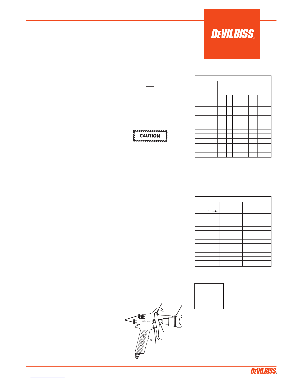
DESCRIPTION
The MBC-510 standard spray gun has a
removable sprayhead; nickel plated brass
fluid passages; a stainless steel fluid tip and
needle to reduce wear; forged aluminum
gun body; large air and fluid passages for
high capacity use and a cartridge type air
valve to minimize repairs.
Nozzle combinations are listed in Chart 1.
Refer to the Spray Gun Catalog, I-2008, for
information regarding air cap and fluid tip
characteristics.
OPERATION
Strain material thru 60 or 90 mesh screen.
Adjust fluid pressure to deliver the desired
paint volume. Adjust air pressure and flow
to provide a uniform dispersion of atomized
paint throughout the pattern. Keep air pressure as low as possible to minimize bounce
- back and overspray. Excessive fluid flow
will result in heavy center spray patterns.
Inadequate flows may cause the pattern
to split. See Spray Gun Guide, SB-2-001,
which is available upon request, for details
concerning set up of spray guns.
PREVENTIVE MAINTENANCE
To clean air cap and fluid tip, brush exterior
with a stiff bristle brush. If necessary to clean
cap holes, use a broom straw or toothpick.
Never use a wire or hard instrument. This
may scratch or burr holes causing a distorted
spray pattern.
To clean fluid passages, remove excess
material at source, then flush with a suitable solvent using a device such as the
SolventSaver™ (see Accessories). Wipe
gun exterior with a solvent dampened cloth.
Never completely immerse in solvent as this
is detrimental to the lubricants and packings.
Note
When replacing the fluid tip or fluid
needle, replace both at the same time.
Using worn parts can cause fluid
leakage. For thinner, less viscous
materials a lapped tip and needle set
is recommended. See Chart 3. Also,
replace the needle packing at this
time. Lightly lubricate the threads
of the fluid tip before reassembling.
Torque to 20-25 ft. lbs. Do not over
tighten the fluid tip.
To prevent damage to the fluid tip (5)
or fluid needle (11), be sure to either
1) pull the trigger and hold while
tightening or loosening the fluid tip
or 2) remove fluid needle adjusting
screw (32) to relieve spring pressure
against needle collar.
SPRAY GUN LUBRICATION
Daily, apply two drops of •SSL-10 spray gun
lube (see Accessories) at trigger bearing stud
(34) and the stem of the air valve (15) where
it enters the air valve assembly. The shank
of the fluid needle (11) where it enters the
packing nut (10) should also be oiled. The
fluid needle packing (9) should be kept soft
and pliable by periodic lubrication. Make
sure the sprayhead (8) and retaining ring (1
or 2) threads are clean and free of foreign
material. Before assembling retaining ring
to sprayhead, clean the threads thoroughly,
then add two drops of SSL-10 spray gun
lube to threads. The fluid needle spring (31)
and air valve spring (16) should be coated
with a very light grease, making sure that
any excess grease will not clog the air passages. For best results, lubricate the points
indicated, daily.
• Material Safety Data Sheet available from
DeVilbiss upon request.
A. Trigger Points
B. Packing
C. Adjusting Valves
D. Threads
C
A
B
D
CHART 1
Nozzle Combinations
Air Cap Sizes
Order From
Chart 2
24 P P P
30 P S P P
58 P/S S P P
62HD P
64HD P
69HD P
80 S
704 P P
765 P P P
777 P P
797 P P
9000 S
P - Pressure Feed Combination
S - Suction Feed Combination
CHART 2
Air Caps
No. on Ref. Nos. (1) Ref. No. (3)
Cap Air Cap Air Cap
Order with Ring Less Ring
24 AV-40-24
30 MB-4039-30
58 AV-439-58
62HD MB-4039-62HD
64HD MB-4039-64HD
69HD MB-4039-69HD
80 MB-4039-80
704 AV-1239-704
765 AV-1239-765
777 31767-777
797 AV-1239-797
9000 AV-440-9000
CA PROP
65
Fluid Tip and Needle Sizes Order
From Chart 3
AC D E EX FF FX
PROP 65 WARNING
WARNING: This product
contains chemicals known
to the State of California to
cause cancer and birth
defects or other
reproductive harm.
SB-2-301-V (7/2014) 1 / 8
A
EN
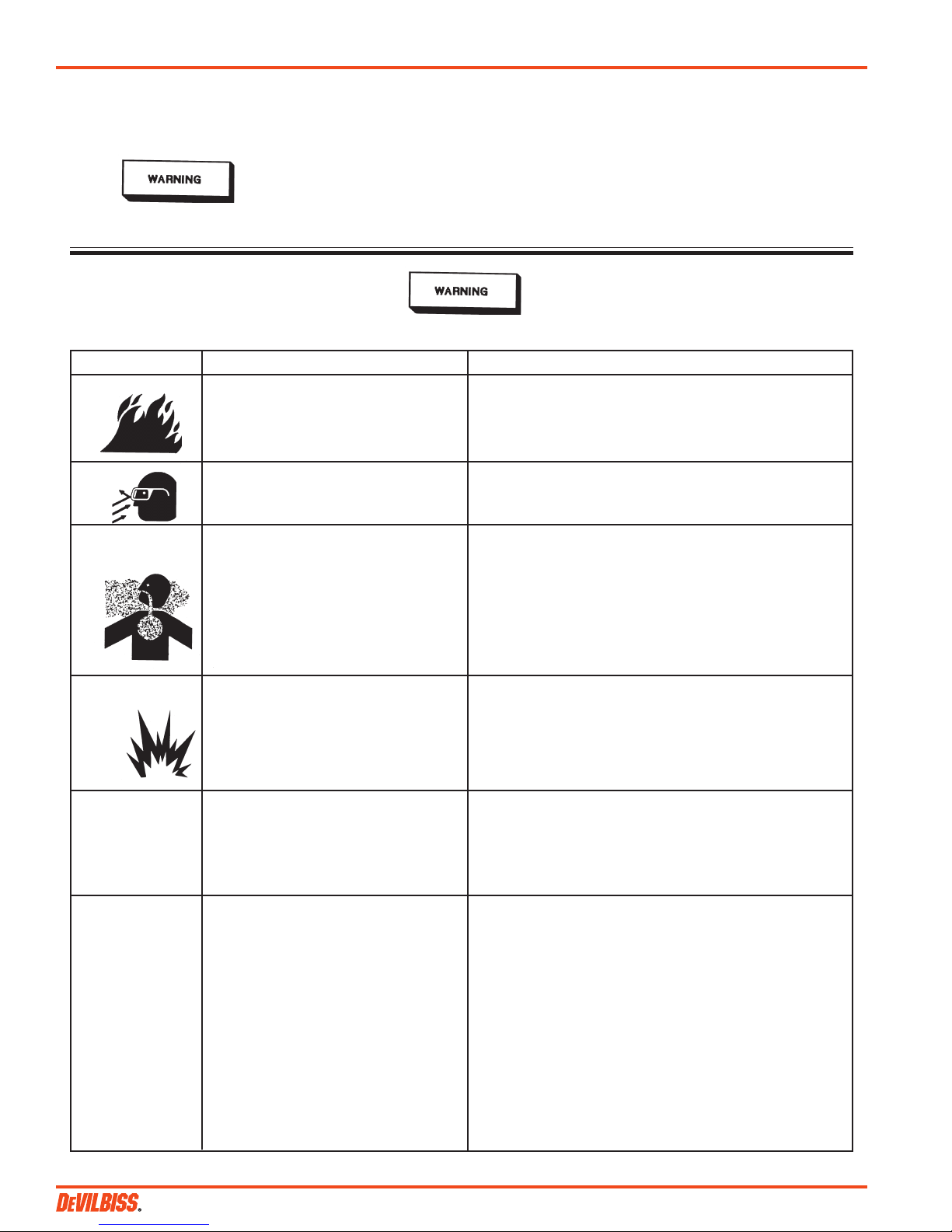
SAFETY PRECAUTIONS
This manual contains information that is improtant for you to know and understand. This information relates to USER SAFETY and
PREVENTING EQUIPMENT PROBLEMS. To help you recognize this information, we use the following symbols. Please pay particular
attention to these sections.
Note
Important information that tells how
Important safety information - A hazard
that may cause serious injury or loss
of life.
The following hazards may occur during the normal use of this equipment. Please read the following chart before using this equipment.
HAZARD CAUSE SAFEGUARDS
Fire Solvent and coatings can be highly flammable Adequate exhaust must be provided to keep air free of
or combustible especially when sprayed. accumulations of flammable vapors.
Smoking must never be allowed in the spray area.
Fire extinguishing equipment must be present in the spray area.
Solvent During use and while cleaning and flushing, Wear eye protection.
Spray solvents can be forcefully expelled from fluid
and air passages. Some solvents can cause
eye injury.
Inhaling Toxic Certain materials may be harmful if inhaled, or Follow the requirements of the Material Safety Data Sheet
Substances if there is contact with the skin. supplied by your coating material manufacturer.
Adequate exhaust must be provided to keep the air free of
accumulations of toxic materials.
Use a mask or respirator whenever there is a chance of inhaling
sprayed materials. The mask must be compatible with the material
being sprayed and its concentration. Equipment must be as
prescribed by an industrial hygienist or safety expert, and be
NIOSH approved.
Explosion Hazard - Halogenated hydrocarbon solvents - for The MBC-510 can be used with these solvents.
Materials example; methylene chloride and 1, 1, 1 - However, aluminum is widely used in other spray application
Trichloroethylene are not chemically compatible equipment - such as material pumps, regulators, valves and cups.
with the aluminum that might be used in many Check all equipment items before use and make sure they can
system components. The chemical reaction also be used safely with these solvents. Read the label or
caused by these solvents reacting with data sheet for the material you intend to spray. If in doubt as to
aluminum can become violent and lead to whether or not a coating or cleaning material is compatible, contact
an equipment explosion. your material supplier.
General Safety Improper operation or maintenance of equipment. Operators should be given adequate training in the safe use &
maintenance of the equipment (in accordance with the requirements
of NFPA-33, Chapter 15). Users must comply with all local &
national codes of practice & insurance company requirements governing
ventilation, fire precautions, operation, maintenance and housekeeping.
These are OSHA Sections 1910.94 and 1910.107 and NFPA-33.
to prevent damage to equipment, or
how to avoid a situation that may cause
minor inury.
Information that you should pay
special attention to.
Cumulative Trauma Use of hand tools may cause cumulative trauma Pain, tingling, or numbness in the shoulder, forearm, wrist, hands or
Disorders (“CTD’s”) disorders (“CTD’s”). fingers, especially during the night, may be early symptoms of a CTD’s, or
musculo- CTD. Do not ignore them. Should you experience any such
skeletal disorders, CTD's when using hand tools, tend to affect symptoms, see a physician immediately. Other early symptoms may
involve damage to the upper extremities. Factors which may include vague discomfort in the hand, loss of manual dexterity, and
the hands, wrist, increase the risk of developing a CTD include: nonspecific pain in the arm. Ignoring early symptoms and continued
elbows, shoulders, repetitive use of the arm, wrist & hand can lead to serious disability.
neck and back. Carpal 1. High frequency of the activity. Risk is reduced by avoiding or lessening factors 1-7.
tunnel syndrome and 2. Excessive force, such as gripping, pinching,
tendinitis (such as or pressing with the hands and fingers.
tennis elbow or rotator 3. Extreme or awkward finger, wrist, or arm.
cuff syndrome) are positions.
examples of CTD’s. 4. Excessive duration of the activity.
5. Tool vibration.
6. Repeated pressure on a body part.
7. Working in cold temperatures.
CTD’s can also be caused by such activities
as sewing, golf, tennis bowling, to name a few.
SB-2-301-V (7/2014)2 / 8

CHART 3
Fluid Tips and Needles
Ref. No. 5
Fluid Tip
AV-2115-AC
AV-2115-D P-MBC-430-D MBC-496-DEX AV-4915-D MBC-4397-D
AV-2115-E P-MBC-430-E MBC-444-E AV-4915-E MBC-4397-E
AV-2115-EX P-MBC-430-EX MBC-496-DEX
AV-2115-FF P-MBC-430-FF MBC-444-FF AV-4915-FF MBC-4397-FF
AV-2115-FX P-MBC-430-FX MBC-444-FX
PARTS LIST
Ref. Replacement Individual
No. Part No. Description Parts Required
1 See Chart 2 Air Cap/Retaining Ring 1
2 MBC-368 Retaining Ring for Ref. No. 3 & 4 1
3 See Chart 2 Air Cap Less Retaining Ring 1
4 See Chart 3 Sprayhead Assembly 1
5 See Chart 3 Fluid Tip 1
•6 AV-1-K5 Gasket Kit (Kit of 5) 1
7 MBC-1225 Baffle 1
8 P-MBC-402 Sprayhead Body 1
•9 A-23-K10 Packing Kit (Kit of 10) 1
10 MB-19-K5 Packing Nut Kit (Kit of 5) 1
11 See Chart 3 Fluid Needle 1
• 12 JGA-14-K25 Snap ring Kit (Kit of 25) 1
• 13 JGA-15-K25 Washer Kit (Kit of 25) 1
• 14 JGS-26-K25 U-Cup Kit (Kit of 25) 1
• 15 JGS-431-K25 Air Valve Kit (Kit of 25) 1
• 16 MBD-12-K25 Spring Kit (Kit of 25) 1
• 17 JGS-72-K10 Gasket Kit (Kit of 10) 1
18 JGS-449-1 Valve Assembly 1
• 19 MBC-1226-K10 Gasket Kit (Kit of 10) 1
20 MBC-67 Locking Bolt 1
21 MBC-498-1 Fan Adjustment Valve 1
22 --- Washer 1
• 23 --- Packing 1
24 --- Packing Nut 1
25 --- Knob 1
• 26 --- Screw 1
27 MBC-415 Cylinder Assembly 1
• 28 CV-5-K5 Gasket Kit (Kit of 5) 1
29 --- Cylinder 1
30 MBC-33 Plunger 1
• 31 MBC-29-K5 Spring (Kit of 5) 1
32 MBC-39 Screw 1
33 P-MB-51 Air Inlet Adapter 1/4" NPS 1
34 --- Trigger Bearing Stud 1
•35 --- Screw 1
36 JGS-478 Stud and Screw Kit 1
(3 studs, 5 screws in kit)
37 JGS-477-1 Trigger, Stud and Screw Kit 1
(Kit includes 1 each)
#38 P-MBC-428-3 Spray gun less spray head 1
• A quantity of necessary parts is included in repair kit KK-4058-1 for
complete gun repair and should be kept on hand for service convenience.
# Ref. No. 38 includes Ref. Nos. 12-37.
Suffixes -K5 and -K10 designates kits of multiple parts.
Example: AV-1-K5 is a kit of 5 gaskets.
Ref. No. 4
Sprayhead
Assy.
————
Ref. No. 11
Fluid Needle
MBC-496-C
Optional 303 S/S Tip Needle
U.H.M.W. Poly.
No. on Tip 5 Ref. No. 39
EN
SB-2-301-V (7/2014) 3 / 8
 Loading...