

DeVilbiss LN1080H23M-1 Owner's Manual
OWNERS MANUAL FOR
TWO-STAGE
AIR COMPRESSOR
Model No.
LN1080H23M-1
Specification Chart
Model No.
Horsepower
Voltage/Hertz/Phase
Minimum Branch Circuit Requirement
*Fuse Type
Air Tank Capacity
Approximate Cut-in Pressure
Approximate Cut-out Pressure
SCFM @ 175 PSIG
Magnetic Starter
*A circuit breaker is preferred. Use only a fuse or circuit breaker that is the same rating as the
branch circuit the air compressor is operated on. If the air compressor is connected to a
circuit protected by fuses, use dual element time delay fuses (Buss Fusetron Type "T" only).
In the unlikely event you should have a problem with this product or if you are missing any parts, it is not necessary
to return it to the store where you purchased it. Simply call our toll free number and talk with our Service
Representative.
Required (Included on Compressor)
LN1080H23M-1
10
208/230/460/60 HZ/3 PHASE
30 Amp
Fusetron Type "T"
80 Gal. ASME
140 PSIG
175 PSIG
34.2
CALL TOLL FREE 1-800-888-2468, Ext. 2
MGP-LN1080H2-1A Rev. 1 3/13/00
OUR OFFICE HOURS ARE FROM
8 a.m. to 4:30 p.m. (CST)
MONDAY THROUGH FRIDAY
DeVilbiss Air Power Company • 213 Industrial Dr. • Jackson, TN 38301-9615
TABLE OF CONTENTS
Page
SAFETY GUIDELINES .................................. 2
WARNING CHART ........................................ 3-4
SPECIFICATIONS ......................................... 5
GLOSSARY ................................................... 5
DUTY CYCLE ................................................ 5
GENERAL INFORMATION ........................... 6
ON-RECEIPT INSPECTION .......................... 6
DESCRIPTION OF OPERATION .................. 7
INSTALLATION AND
BREAK-IN PROCEDURES ........................... 8-11
Location of Air Compressor......................... 8
Air Compressor Anchoring Methods ........... 8
Wiring Instructions and Diagram ................. 9
Voltage and Circuit Protection ..................... 9
Air Filter Installation ...................................... 10
Outlet Valve Installation ................................ 10
Break-in Procedures ..................................... 10
Additional Regulators and Controls .............. 10
Lubrication and Oil ....................................... 10
Piping and Diagram ...................................... 11
OPERATING PROCEDURES ........................ 12
Page
MAINTENANCE ............................................. 13
SERVICE INSTRUCTIONS ............................ 14-17
Air Filter-Inspection and Replacement ........ 14
Oil-Checking and Changing ......................... 14
Recommended Oils ..................................... 14
Check Valve-Inspection and Replacement .. 14-15
Safety Valve-Inspection and Replacement . 15
Adjusting Belt Tension ................................. 16
Motor Pulley and Flywheel Alignment ......... 16
Additional Service........................................ 17
STORAGE...................................................... 17
TROUBLESHOOTING GUIDE ..................... 18-21
COMPRESSOR DIAGRAM ........................... 22
COMPRESSOR PARTS LIST........................ 23
COMPRESSOR PUMP DIAGRAM ................ 24
PUMP PARTS LIST ....................................... 25
SERVICE NOTES .......................................... 26
WARRANTY STATEMENT ............................ 27
HOW TO ORDER REPAIR PARTS ..... Back Cover
SAFETY GUIDELINES - DEFINITIONS
This manual contains information that is important for you to know and understand. This information relates to protecting YOUR
SAFETY and PREVENTING EQUIPMENT PROBLEMS. To help you recognize this information, we use the symbols to the right.
Please read the manual and pay attention to these sections.
DANGER indicates an imminently hazardous situation which, if not
avoided, will result in death or serious injury.
WARNING indicates a potentially hazardous situation which, if not
avoided, could result in death of serious injury.
MGP-LN1080H2-1A Rev. 1 3/13/00
CAUTION indicates a potentially hazardous situation which, if not
avoided, may result in minor or moderate injury.
CAUTION used without the safety alert symbol indicates a
potentially hazardous situation which, if not avoided, may result
in property damage.
2—ENG
IMPORTANT SAFETY INSTRUCTIONS
SAVE THESE INSTRUCTIONS
IMPROPER OPERATION OR MAINTENANCE OF THIS PRODUCT COULD RESULT IN SERIOUS INJURY AND PROPERTY
DAMAGE. READ AND UNDERSTAND ALL WARNINGS AND OPERATING INSTRUCTIONS BEFORE USING THIS EQUIPMENT.
HAZARD
RISK OF EXPLOSION OR FIRE
WHAT CAN HAPPEN
IT IS NORMAL FOR ELECTRICAL CONTACTS WITHIN THE
MOTOR AND PRESSURE SWITCH TO SPARK.
IF ELECTRICAL SPARKS FROM COMPRESSOR COME INTO
CONTACT WITH FLAMMABLE VAPORS, THEY MAY IGNITE,
CAUSING FIRE OR EXPLOSION.
RESTRICTING ANY OF THE COMPRESSOR VENTILATION
OPENINGS WILL CAUSE SERIOUS OVERHEATING AND
COULD CAUSE FIRE.
UNATTENDED OPERATION OF THIS PRODUCT COULD
RESULT IN PERSONAL INJURY OR PROPERTY DAMAGE.
RISK OF BURSTING
HOW TO PREVENT IT
ALWAYS OPERATE THE COMPRESSOR IN A WELL VENTILATED AREA FREE OF COMBUSTIBLE MATERIALS,
GASOLINE OR SOLVENT VAPORS.
IF SPRAYING FLAMMABLE MATERIALS, LOCATE COMPRESSOR AT LEAST 20 FEET AWAY FROM SPRAY AREA. AN
ADDITIONAL LENGTH OF HOSE MAY BE REQUIRED.
STORE FLAMMABLE MATERIALS IN A SECURE LOCATION
AWAY FROM COMPRESSOR.
NEVER PLACE OBJECTS AGAINST OR ON TOP OF COMPRESSOR. OPERATE COMPRESSOR IN AN OPEN AREA AT
LEAST 12 INCHES AWAY FROM ANY WALL OR OBSTRUC-
TION THAT WOULD RESTRICT THE FLOW OF FRESH AIR TO
THE VENTILATION OPENINGS.
OPERATE COMPRESSOR IN A CLEAN, DRY, WELL VENTILATED
AREA. DO NOT OPERATE UNIT INDOORS OR IN ANY CON-
FINED AREA.
ALWAYS REMAIN IN ATTENDANCE WITH THE PRODUCT
WHEN IT IS OPERATING.
AIR TANK: THE FOLLOWING CONDITIONS COULD LEAD TO A WEAKENING OF THE TANK, AND RESULT IN A
VIOLENT TANK EXPLOSION AND COULD CAUSE PROPERTY DAMAGE OR SERIOUS INJURY.
WHAT CAN HAPPEN
1. FAILURE TO PROPERLY DRAIN CONDENSED WATER
FROM THE TANK, CAUSING RUST AND THINNING OF THE
STEEL TANK.
2. MODIFICATIONS OR ATTEMPTED REPAIRS TO THE TANK.
3. UNAUTHORIZED MODIFICATIONS TO THE UNLOADER
VALVE, SAFETY VALVE, OR ANY OTHER COMPONENTS
WHICH CONTROL TANK PRESSURE.
4. EXCESSIVE VIBRATION CAN WEAKEN THE AIR TANK
AND CAUSE RUPTURE OR EXPLOSION.
ATTACHMENTS & ACCESSORIES:
EXCEEDING THE PRESSURE RATING OF AIR TOOLS, SPRAY
GUNS, AIR OPERATED ACCESSORIES, TIRES AND OTHER
INFLATABLES CAN CAUSE THEM TO EXPLODE OR FLY
APART, AND COULD RESULT IN SERIOUS INJURY.
HOW TO PREVENT IT
DRAIN TANK DAILY OR AFTER EACH USE. IF TANK DEVELOPS A LEAK, REPLACE IT IMMEDIATELY WITH A NEW TANK OR
REPLACE THE ENTIRE COMPESSOR.
NEVER DRILL INTO, WELD, OR MAKE ANY MODIFICATIONS
TO THE TANK OR ITS ATTACHMENTS.
THE TANK IS DESIGNED TO WITHSTAND SPECIFIC OPERATING
PRESSURES. NEVER MAKE ADJUSTMENTS OR PARTS
SUBSTITUTIONS TO ALTER THE FACTORY SET OPERATING
PRESSURES.
FOR ESSENTIAL CONTROL OF AIR PRESSURE, YOU MUST
INSTALL A PRESSURE REGULATOR AND PRESSURE GAUGE
TO THE AIR OUTLET OF YOUR COMPRESSOR. FOLLOW THE
EQUIPMENT MANUFACTURERS RECOMMENDATION AND
NEVER EXCEED THE MAXIMUM ALLOWABLE PRESSURE
RATING OF ATTACHMENTS. NEVER USE COMPRESSOR TO
INFLATE SMALL LOW-PRESSURE OBJECTS SUCH AS
CHILDREN’S TOYS, FOOTBALLS, BASKETBALLS. ETC.
3—ENG
MGP-LN1080H2-1A Rev. 1 3/13/00
HAZARD
RISK FROM FLYING OBJECTS
WHAT CAN HAPPEN
THE COMPRESSED AIR STREAM CAN CAUSE SOFT TISSUE
DAMAGE TO EXPOSED SKIN AND CAN PROPEL DIRT, CHIPS,
LOOSE PARTICLES AND SMALL OBJECTS AT HIGH SPEED,
RESULTING IN PROPERTY DAMAGE OR PERSONAL INJURY.
RISK TO BREATHING
WHAT CAN HAPPEN
THE COMPRESSED AIR FROM YOUR COMPRESSOR IS NOT
SAFE FOR BREATHING! THE AIR STREAM MAY CONTAIN
CARBON MONOXIDE, TOXIC VAPORS OR SOLID PARTICLES
FROM THE TANK.
HOW TO PREVENT IT
ALWAYS WEAR ANSI Z87.1 APPROVED SAFETY GLASSES
WITH SIDE SHIELDS WHEN USING THE COMPRESSOR.
NEVER POINT ANY NOZZLE OR SPRAYER TOWARD ANY
PART OF THE BODY OR AT OTHER PEOPLE OR ANIMALS.
ALWAYS TURN THE COMPRESSOR OFF AND BLEED PRESSURE FROM THE AIR HOSE AND TANK BEFORE ATTEMPTING
MAINTENANCE, ATTACHING TOOLS OR ACCESSORIES.
HOW TO PREVENT IT
ALWAYS OPERATE AIR COMPRESSOR OUTSIDE IN A CLEAN,
WELL VENTILATED AREA. AVOID ENCLOSED AREAS SUCH AS
GARAGES, BASEMENTS, STORAGE SHEDS, WHICH LACK A
STEADY EXCHANGE OF AIR. KEEP CHILDREN, PETS AND
OTHERS AWAY FROM AREA OF OPERATION.
NEVER INHALE AIR FROM THE COMPRESSOR EITHER
DIRECTLY OR FROM A BREATHING DEVICE CONNECTED TO
THE COMPRESSOR.
SPRAYED MATERIALS SUCH AS PAINT, PAINT SOLVENTS,
PAINT REMOVER, INSECTICIDES, WEED KILLERS, CONTAIN
HARMFUL VAPORS AND POISONS.
RISK OF ELECTRICAL SHOCK
WHAT CAN HAPPEN
YOUR AIR COMPRESSOR IS POWERED BY ELECTRICITY.
LIKE ANY OTHER ELECTRICALLY POWERED DEVICE, IF IT IS
NOT USED PROPERLY IT MAY CAUSE ELECTRIC SHOCK.
REPAIRS ATTEMPTED BY UNQUALIFIED PERSONNEL CAN
RESULT IN SERIOUS INJURY OR DEATH BY ELECTROCUTION.
ELECTRICAL GROUNDING: FAILURE TO PROVIDE ADEQUATE
GROUNDING TO THIS PRODUCT COULD RESULT IN SERIOUS
INJURY OR DEATH FROM ELECTROCUTION. SEE GROUND-
ING INSTRUCTIONS.
WORK IN AN AREA WITH GOOD CROSS-VENTILATION. READ
AND FOLLOW THE SAFETY INSTRUCTIONS PROVIDED ON
THE LABEL OR SAFETY DATA SHEETS FOR THE MATERIAL
YOU ARE SPRAYING. USE A NIOSH/MSHA APPROVED
RESPIRATOR DESIGNED FOR USE WITH YOUR SPECIFIC
APPLICATION.
HOW TO PREVENT IT
NEVER OPERATE THE COMPRESSOR OUTDOORS WHEN IT IS
RAINING OR IN WET CONDITIONS.
NEVER OPERATE COMPRESSOR WITH COVER COMPONENTS
REMOVED OR DAMAGED.
ANY ELECTRICAL WIRING OR REPAIRS REQUIRED ON THIS
PRODUCT SHOULD BE PERFORMED BY AUTHORIZED
SERVICE CENTER PERSONNEL IN ACCORDANCE WITH
NATIONAL AND LOCAL ELECTRICAL CODES.
MAKE CERTAIN THAT THE ELECTRICAL CIRCUIT TO WHICH
THE COMPRESSOR IS CONNECTED PROVIDES PROPER
ELECTRICAL GROUNDING, CORRECT VOLTAGE AND
ADEQUATE FUSE PROTECTION.
MGP-LN1080H2-1A Rev. 1 3/13/00
4—ENG
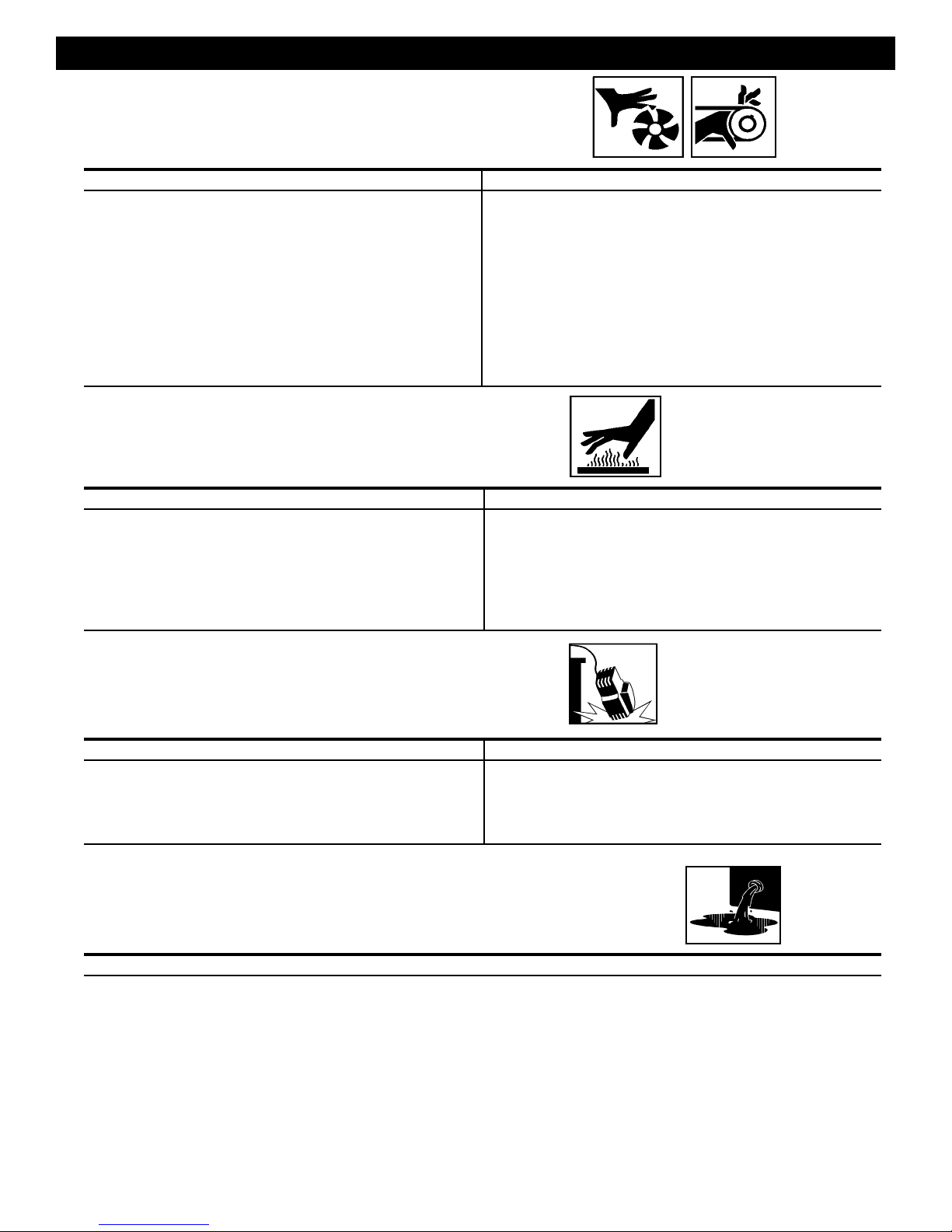
HAZARD
RISK FROM MOVING PARTS
WHAT CAN HAPPEN
MOVING PARTS SUCH AS THE PULLEY, FLYWHEEL AND BELT
CAN CAUSE SERIOUS INJURY IF THEY COME INTO CONTACT
WITH YOU OR YOUR CLOTHING.
ATTEMPTING TO OPERATE COMPRESSOR WITH DAMAGED
OR MISSING PARTS OR ATTEMPTING TO REPAIR COMPRESSOR WITH PROTECTIVE SHROUDS REMOVED CAN
EXPOSE YOU TO MOVING PARTS AND CAN RESULT IN
SERIOUS INJURY.
RISK OF BURNS
WHAT CAN HAPPEN
TOUCHING EXPOSED METAL SUCH AS THE COMPRESSOR
HEAD OR OUTLET TUBES, CAN RESULT IN SERIOUS BURNS.
HOW TO PREVENT IT
NEVER OPERATE THE COMPRESSOR WITH GUARDS OR
COVERS WHICH ARE DAMAGED OR REMOVED.
ANY REPAIRS REQUIRED ON THIS PRODUCT SHOULD BE
PERFORMED BY AUTHORIZED SERVICE CENTER PERSONNEL.
HOW TO PREVENT IT
NEVER TOUCH ANY EXPOSED METAL PARTS ON COMPRESSOR DURING OR IMMEDIATELY AFTER OPERATION. COMPRESSOR WILL REMAIN HOT FOR SEVERAL MINUTES AFTER
OPERATION.
DO NOT REACH AROUND PROTECTIVE SHROUDS OR ATTEMPT
MAINTENANCE UNTIL UNIT HAS BEEN ALLOWED TO COOL.
RISK OF FALLING
WHAT CAN HAPPEN
A PORTABLE COMPRESSOR CAN FALL FROM A TABLE,
WORKBENCH OR ROOF CAUSING DAMAGE TO THE COM-
PRESSOR AND COULD RESULT IN SERIOUS INJURY OR
DEATH TO THE OPERATOR.
RISK OF PROPERTY DAMAGE WHEN TRANSPORTING
COMPRESSOR
(Fire, Inhalation, Damage to Vehicle Surfaces)
WHAT CAN HAPPEN
OIL CAN LEAK OR SPILL AND COULD RESULT IN FIRE OR
BREATHING HAZARD, SERIOUS INJURY OR DEATH CAN RESULT.
OIL LEAKS WILL DAMAGE CARPET, PAINT OR OTHER SURFACES
IN VEHICLES OR TRAILERS.
HOW TO PREVENT IT
ALWAYS OPERATE COMPRESSOR IN A STABLE SECURE
POSITION TO PREVENT ACCIDENTAL MOVEMENT OF THE
UNIT. NEVER OPERATE COMPRESSOR ON A ROOF OR
OTHER ELEVATED POSITION. USE ADDITIONAL AIR HOSE
TO REACH HIGH LOCATIONS.
HOW TO PREVENT IT
ALWAYS PLACE COMPRESSOR ON A PROTECTIVE MAT WHEN
TRANSPORTING TO PROTECT AGAINST DAMAGE TO VEHICLE
FROM LEAKS. REMOVE COMPRESSOR FROM VEHICLE IMMEDIATELY UPON ARRIVAL AT YOUR DESTINATION.
5—ENG
MGP-LN1080H2-1A Rev. 1 3/13/00

SPECIFICATIONS
Refer to cover page for the specifications of your compressor. Use only a fuse or circuit breaker that is the same rating
as the branch circuit the air compressor is operated on. If the compressor is connected to a circuit protected by fuses,
use dual element time delay fuses, as noted in specification chart.
Improper electrical installation of this product
may void its warranty and your fire insurance.
Have circuit wiring performed by qualified personnel such as a licensed electrician who is
familiar with the current national electric code
and any prevailing local electrical codes.
GLOSSARY
CFM: Cubic feet per minute.
SCFM: Standard cubic feet per minute; a unit of
measure of air delivery.
PSIG: Pounds per square inch gauge; a unit of measure
of pressure.
ASME: American Society of Mechanical Engineers;
made, tested, inspected and registered to meet the
standards of the ASME.
California Code: Unit may comply with California
Code 462 (L) (2)/(M) (2). Specification/Model Label is on
the side of the tank on units that comply with California
Code.
DUTY CYCLE
Cut-In Pressure: While the motor is off, air tank
pressure drops as you continue to use your accessory.
When the tank pressure drops to a certain low level the
motor will restart automatically. The low pressure at
which the motor automatically restarts is called “cut-in
pressure.”
Cut-Out Pressure: When you turn on your air compressor and it begins to run, air pressure in the air tank
begins to build. It builds to a certain high pressure
before the motor automatically shuts off - protecting
your air tank from pressure higher than its capacity. The
high pressure at which the motor shuts off is called "cutout pressure."
To Lock Out Power: Place a lock on the line power
switch so no one else can turn on the power.
All DeVilbiss Air Power manufactured air compressors
should be operated on not more than a 50% duty cycle.
This means an air compressor that pumps more than
50% of one hour, is considered misuse, because the air
MGP-LN1080H2-1A Rev. 1 3/13/00
Compressor is undersized for the required air demand.
Maximum compressor pumping time per hour is 30
minutes.
6—ENG

GENERAL INFORMATION
You have purchased a complete compressor outfit
consisting of an air compressor, air tank, electric motor,
and associated controls and instruments. The outfit you
have selected is a stationary model and contains a two
stage air compressor pump.
Your new compressor outfit can be used for operating
paint sprayers, air tools, grease guns, air brushes,
caulking guns, sandblasters, inflating tires, etc.
An air pressure regulator is usually necessary for most
applications. An air line filter is normally required for
removal of moisture and oil vapor in compressed air
when a paint spray gun is used.
An in-line lubricator is often required for air tools to
prolong tool life.
Separate air transformers which combine the functions
ON-RECEIPT INSPECTION
of air regulation and/or moisture and dirt removal should
be used where applicable.
A regularly scheduled program of preventive maintenance will help provide the long life that has been
designed into your compressor outfit. Before operating
or performing any maintenance on your compressor,
refer to this manual. To keep your compressor in good
working order, refer to these publications often and
perform preventive maintenance steps as recommended.
Each air compressor outfit is carefully checked before
shipment. With improper handling, damage may result
in transit and cause problems in compressor operation.
Immediately upon arrival, check equipment for both
concealed and visible damages to avoid expenses being
incurred to correct such problems. This should be done
regardless of any visible signs of damage to the shipping
container. Report any damages to carrier and arrange for
inspection of goods immediately.
For the location or a listing of the nearest DeVilbiss Air
Power Authorized Warranty Service Center, call our toll
free number at 1-800-888-2468, Ext. 2, then 1.
7—ENG
MGP-LN1080H2-1A Rev. 1 3/13/00

DESCRIPTION OF OPERATION
Drain Valve: At the base of the air tank to drain
condensation at the end of each use.
ON/AUTO-OFF Switch: Turn this switch ON to provide automatic power to the pressure switch and OFF
to remove power.
Air Intake Filter: This filter is designed to clean air
coming into the pump. This filter must always be clean
and ventilation openings free from obstructions. See
"Maintenance".
Air Compressor Pump: In two stage compressors, air
is first compressed to an intermediate pressure in the
large bore cylinder, and after passing through an intercooler, the air is further compressed to a higher pressure in the smaller bore cylinder. This process continues until the air tank pressure reaches the factory set
cutoff pressure. At that point the pressure switch shuts
the electric motor off.
Check Valve: When the air compressor is operating,
the check valve is "open", allowing compressed air to
enter the air tank. When the air compressor reaches
"cut-out" pressure, the check valve "closes", allowing
air pressure to remain inside the air tank.
Pressure Release Valve: The pressure release valve
located on the side of the pressure switch, is designed
to automatically release compressed air from the compressor head and the outlet tube when the air compressor reaches "cut-out" pressure or is shut off. If the air
is not released, the motor will try to start, but will be
unable to. The pressure release valve allows the motor
to restart freely. When the motor stops running, air will
be heard escaping from the valve for a few seconds. No
air should be heard leaking when the motor is running.
Pressure Switch: The pressure switch automatically
starts the motor when the air tank pressure drops below
the factory set "cut-in" pressure. It stops the motor
when the air tank pressure reaches the factory set "cutout" pressure.
Shut-off Valve: Turn the knob counterclockwise to
open the valve and clockwise to close.
Air Tank Safety Valve: If the pressure switch does
not shut off the air compressor at its cut-out pressure
setting, the safety valve will protect against high pressure by "popping off" at its factory set pressure (slightly
higher than the pressure switch cut-out setting).
Aftercooler Safety Valve: On two stage compressor
units, safety valve is provided to prevent over-pressurization of the aftercooler. The valve will protect the
aftercooler by "popping off" at its factory set pressure.
Regulator: An air pressure regulator or a separate air
transformer which combines the functions of air regulation and/or moisture and dirt removal is recommended
for most applications.
Tank Pressure Gauge: The tank pressure gauge
indicates the reserve air pressure in the tank. On outfits
with no pressure regulator, this is also the pressure
available at the air outlet.
MGP-LN1080H2-1A Rev. 1 3/13/00
8—ENG
INSTALLATION AND BREAK-IN PROCEDURES
Location of the Air Compressor
THE PUMP ASSEMBLY DOES NOT PROVIDE ADEQUATE STABILITY OR SUPPORT
FOR LIFTING THE UNIT. IF THE OUTFIT
MUST BE MOVED, USE THE TANK FOR
LIFTING.
This compressor should be permanently mounted in
place on a level floor. Operate the air compressor in a
clean, dry and well ventilated area. The air intake filter
must be kept clear of obstructions which could reduce air
delivery of the air compressor. The air compressor
should be located at least 12" away from walls or other
obstructions that could interfere with the flow of air
through the fan bladed flywheel. The air compressor
crankcase and head are designed with fins to provide
proper cooling.
The flywheel side of the outfit should be placed toward
the wall and protected with a totally enclosed belt guard.
In no case should the flywheel be closer than 12 to 18
inches from the wall or other obstruction that will interfere
with the flow of air through the fan bladed flywheel. The
area should allow space on all sides for air circulation
and for ease of normal maintenance. Keep the outfit
away from areas which have dirt, vapor and volatile fumes
in the atmosphere which may clog and gum the intake
filter and valves, causing inefficient operation. Where this
is not practical a remote air intake is recommended.
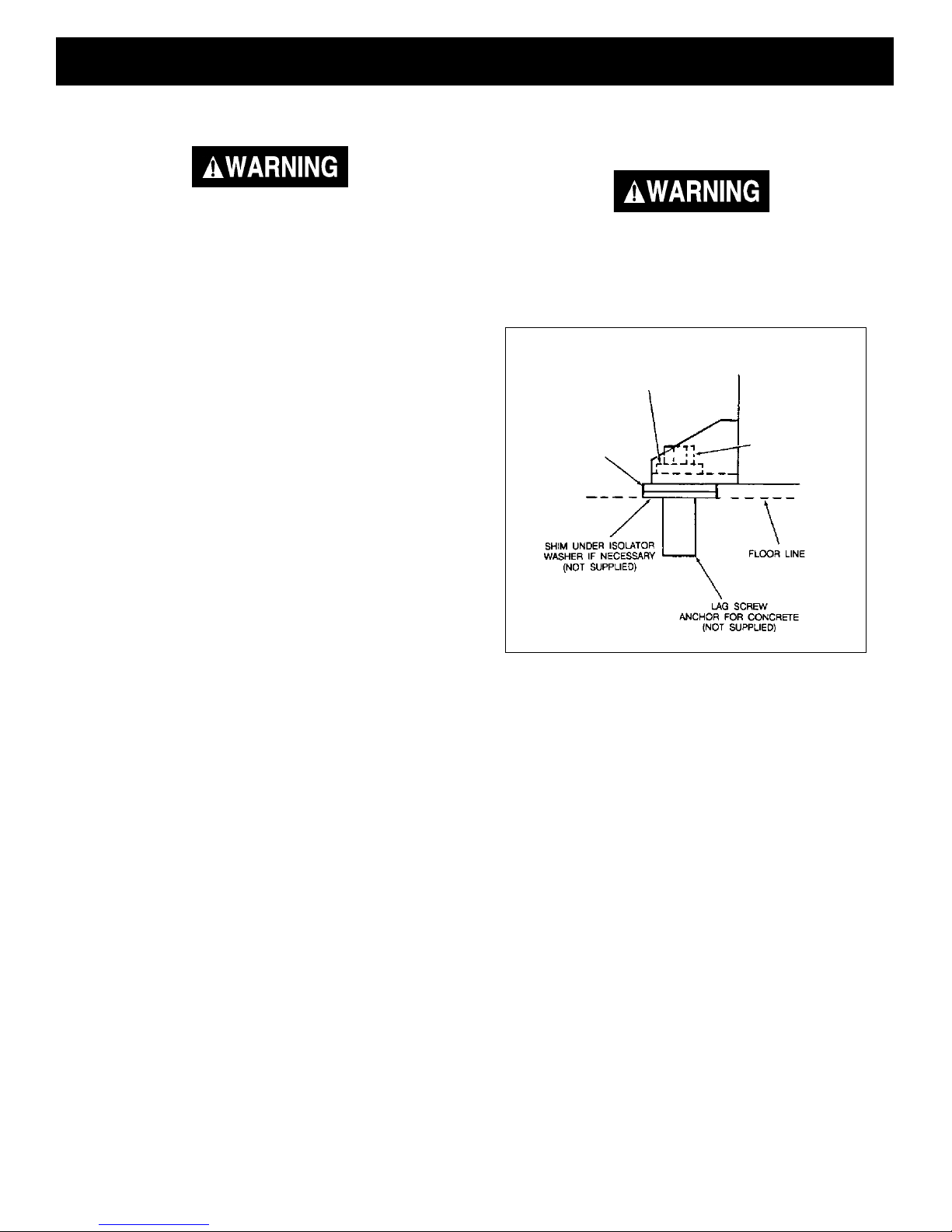
Air Compressor Anchoring
Methods
VIBRATION CAN WEAKEN THE AIR TANK
AND CAUSE AN EXPLOSION. THE COMPRESSOR MUST BE PROPERLY MOUNTED
AS ILLUSTRATED BELOW.
FLAT WASHER
ISOLATOR
WASHER
Anchoring of Horizontal Unit
LAG SCREW
(NOT SUPPLIED)
TORQUE TO
5 TO 10 FT-LB
Note
Where a remote air intake is used, enlarge the size of the air intake piping by
one pipe size for each 10 feet of length.
If humidity is high, an air filter can be installed to
remove excessive moisture. Closely follow instructions packaged with the filter for proper installation. It
must be installed as close as possible to the accessory.
The air compressor should be as near to air outlets as
possible in order to avoid long pipe lines. Do not place
the air compressor where heat is excessive.
Horizontal Units
Horizontal air compressors must be bolted to the floor.
Bolting holes are provided in the base feet. Mount the
air compressor on a solid, level foundation. Support
compressor weight evenly on all four feet. Solid shims
may be used if necessary.
9—ENG
MGP-LN1080H2-1A Rev. 1 3/13/00
 Loading...