

Page 1
SI-2-25-28-R1 (7/2018)1 / 4www.carlisleft.com
Service Instruction
SI-2-25-28-G
Replaces SI-2-25-28-F
KK-4987-2 Gun Repair Kit
(for JGA, JGV, JGHV, JGP, JGPV, LMG,
MSA, MSV, & PGA GUNS)
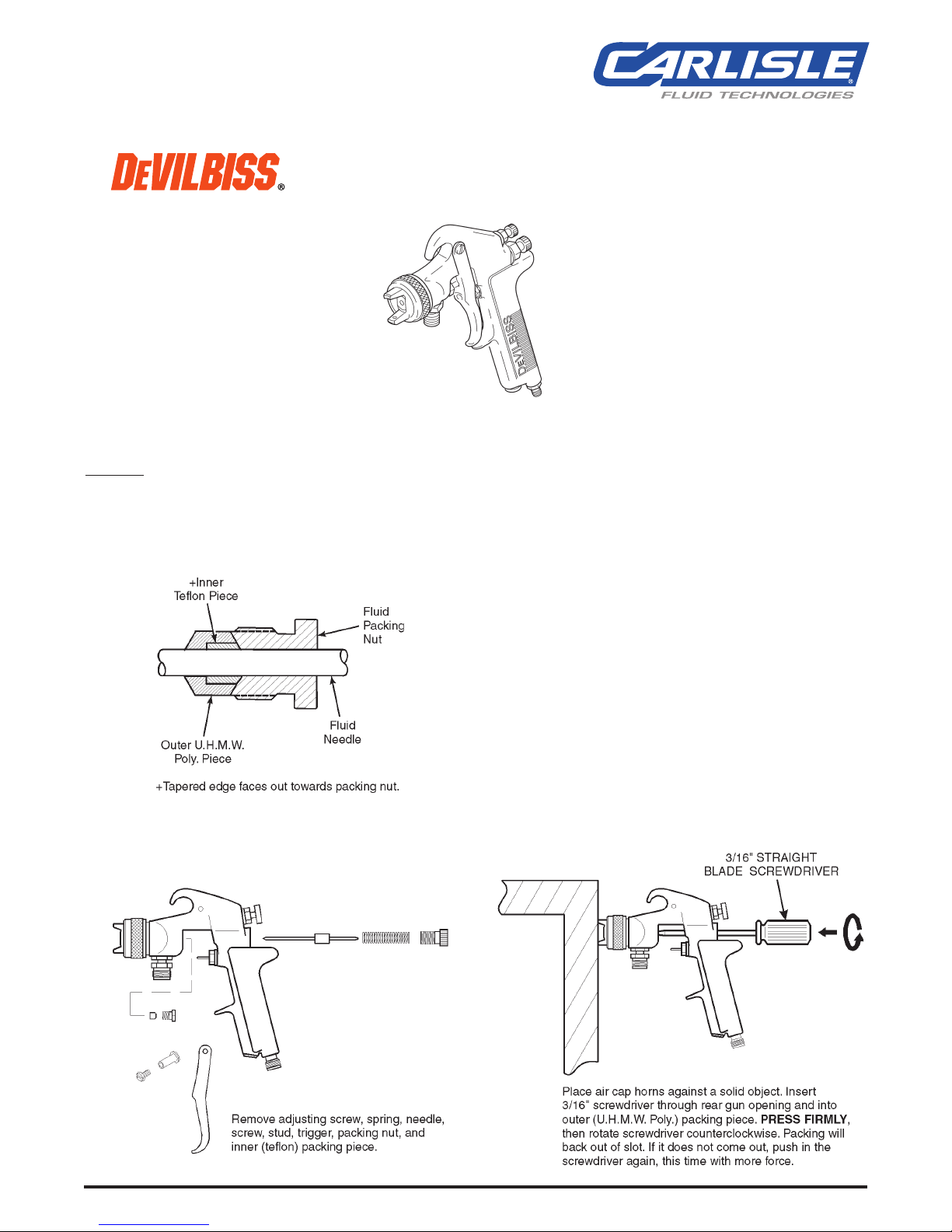
1. Remove adjusting knob, needle spring, spring pad,
and needle from gun.
2. Loosen packing nut and remove.
3. Remove old packing. See disassembly illustration
below.
4. Assemble packing nut to needle.
5. Assemble packing in order shown to needle.
6. Insert needle all the way into gun body seating in tip.
7. Install needle spring, spring pad, and adjusting knob.
8. Thread packing nut into gun body.
9. Tighten packin
g nut in equal increments - no more
than 1/6 turn at a time.
10. After each adjustment, pull needle open and observe
needle closure.
11. If needle snaps shut, continue adjusting nut until
there is evidence of needle bind or slow closing.
12. Back off packing nut 1/12 turn to the point where
needle snaps shut. Packing nut must remain tight
enough to prevent loosening by hand.
13. Pull needle several times to ve
rify needle snaps shut
and check packing nut for looseness.
NOTE 1:
JGV-463 Packing Replacement Instructions
2 piece packing covered by U.S. Patent No. 5,209,501.
Other patents pending.
PACKING REPLACEMENT
INSTRUCTIONS
PACKING REPLACEMENT INSTRUCTIONS
EN
SERVICE INSTRUCTION
KK-4987-2 GUN REPAIR KIT
(FOR JGA, JGV, JGHV, JGP, JGPV, LMG, MSA, MSV, & PGA GUNS)
Page 2
EN
SI-2-25-28-R1 (7/2018)2 / 4www.carlisleft.com
1. Remove adjusting knob, needle spring, spring pad,
and needle from gun.
2. Loosen packing nut and remove.
3. Remove old packing. See disassembly illustration
below.
4. Assemble packing nut to needle.
5. Assemble packing in order shown to needle.
6. Insert needle all the way into gun body seating in tip.
7. Install needle spring, spring pad, and adjusting knob.
8. Thread packing nut into gun body.
9. Tighten packin
g nut in equal increments - no more
than 1/6 turn at a time.
10. After each adjustment, pull needle open and observe
needle closure.
11. If needle snaps shut, continue adjusting nut until
there is evidence of needle bind or slow closing.
12. Back off packing nut 1/12 turn to the point where
needle snaps shut. Packing nut must remain tight
enough to prevent loosening by hand.
13. Pull needle several times to ve
rify needle snaps shut
and check packing nut for looseness.
NOTE 1:
JGV-463 Packing Replacement Instructions
2 piece packing covered by U.S. Patent No. 5,209,501.
Other patents pending.
PACKING REPLACEMENT
INSTRUCTIONS
NOTE 2: GTI-33 Baffle Seal Replacement
5. Install baffle on gun.
6. Install fluid tip and tighten to 20-25 ft-lbs.
NOTE
The seal is designed to be a tight fit
on the baffle. The seal should be
able to be removed using your fingers. If you are unable to remove
the seal using your fingers, insert a
small screwdriver between the outer
lip and the back of the baffle and pry
the seal off.
1. Remove fluid tip.
2. Remove b
affle.
3. Remove seal (7) from baffle.
4. Assemble seal to baffle with angled
side up as shown at right.
NOTE
The seal should be a tight fit on
the baffle. If it is a loose fit on the
baffle, assure that it is assembled with the angled side up.
ANGLED SIDE
SEAL
THICK SIDE
BAFFLE
Pry here if
necessary
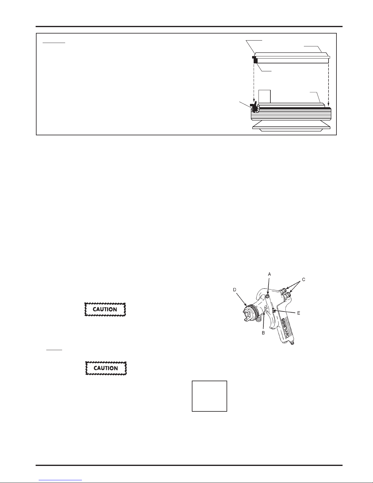
PREVENTIVE MAINTENANCE
SPRAY GUN LUBRICATION
Daily, apply a drop of gun lube at trigger stud screw (15) and
the stem of the air valve (12) where it enters the air valve
assembly. The shank of the fluid needle where it enters the
packing nut should also be lubricated. Make sure baffle
and retaining ring threads are clean and free of foreign
matter. Before assembling air cap to baffle, clean the
retaining ring and baffle threads
thoroughly, then add
two drops of spray gun lube to threads.
The fluid needle spring (4), and air valve spring (13), should
be coated with a very light grease, ensuring that any excess
grease will not clog the air passages. For best results, lubricate the points indicated daily using SSL-10 spray gun lube.
A. Trigger points
B. Packing
C. Adjusting valve
D. Baffle and retaining ring threads
E. Air valve c
artridge
FOR HVLP GUNS ONLY:
NOTE
If the baffle is removed, baffle gasket (7) and
O-ring (8) should be replaced. To prevent damage
to the O-ring during installation, apply gun lube
to exterior of O-ring and ID of baffle.
To clean air cap and fluid tip, brush exterior with a stiff bristle brush. If necessary to clean cap holes, use a broom straw
or toothpick. Never use a wire or hard instrument. Th
is
may scratch or burr holes causing a distorted spray pattern.
To clean fluid passages, remove excess material at source,
then flush with a suitable solvent using a device such as the
Solvent Saver
TM
. Wipe gun exterior with a solvent dampened
cloth. Never completely immerse in solvent as this is detrimental to the performance and gun life expectancy, as well
as destroying the lubricants and packings.
FOR GUNS WITH S.S. FLUID INSERTS ONLY:
To prevent serious gun damage, do not remove
the fluid tip if the fluid inlet adapter has been
removed. The stainless steel fluid insert can break
free (which is non-repairable). Remove the fluid tip
before
removing the fluid inlet adapter. Use a new
gasket before reinstalling the fluid inlet adapter.
To prevent damage to the fluid tip or fluid needle,
be sure to either 1) pull the trigger and hold while
tightening the fluid tip, or 2) remove fluid needle
adjusting screw to relieve spring pressure.
PROP 65 WARNING
WARNING: This product contains chemicals known
to the State of California to cause cancer and
birth defects or other reproductive harm.
CA PROP
65
Page 3

Use AV-1 copper gasket only on
model shown. Do not use with
plastic baffle or threaded baffle.
TYPICAL EXPLODED VIEW
AN EXTRA PART OF EACH HAS BEEN SUPPLIED FOR USE WITH THE OPTIONAL JGA-4005 AIR ADJUSTING VALVE.
* PLEASE SELECT THE VERSION OF BAFFLE GASKET THAT MATCHES THE BAFFLE GASKET ON YOUR GUN.
1
1
1
1
1
1
1
1
TRIGGER STUD
SCREW
15
PART DESCRIPTION
(PARTS SHOWN ACTUAL SIZE)
1
1
1
1
1
1
1
1
1
1
1
1
1
1
1
1
1
1
1
1
1
1
1
1
1
1
1
1
1
1
1
1
1
1
1
1
1
1
1
1
1
1
1
1
1
1
1
1
1
1
–
–
–
–
–
–
1
1
1
1
–
1
1
–
–
–
–
–
–
–
–
1
1
1
1
1
1
1
1
1
1
1
1
1
1
1
1
1
2
2
2
2
2
2
2
2
1
–
–
1
1
1
1
1
1
–
–
1
1
1
1
–
–
–
–
–
–
–
–
1
JGV-463
(See Note 1
on following
page)
SSG-8182
JGD-14
AV-1
MBD-19
JGS-72
FLUID NEEDLE
PACKING (2 PIECE)
AIR VALVE
SPRING
AIR VALVE
U-CUP SEAL
(POLYETHYLENE)
WASHER
(ALUMINUM)
SNAP RING
O-RING
(BUNA-N RUBBER)
BAFFLE GASKET
(POLYETHYLENE)
USED WITH
JGD-402-1 BAFFLE
TIP GASKET
(COPPER)
SPRING PAD
(PTFE)
NEEDLE
SPRING
GASKET
(PTFE)
O-RING
(VITON RUBBER)
14
13
12
11
10
9
8
7*
6
5
4
3
2
1
RETAINING
CLIPS
SMALL
LARGE
JGHV-530
OR
TYPE MSV
TYPE JGA
(JGA-503)
TYPE MSA
(MSA-501/503)
PGA-511
JGA-510,
JGP,
OR
MSA-510
LMG-500 LMG-501
MODEL JGV
(JGV-560,
570, 572)
JGHV-531
OR
MSV-531
JGA-502
OR
PGA-510
GUN MODELS (SEE STAMP ON SIDE OF GUN HANDLE)
QUANTITY OF PARTS REQUIRED
(REPLACE-
MENT
PART NO.
REF
NO.
( See
Caution
above)
(See Note 2
on following
page)
–
–
1
–
–
–
–
–
GTI-33
BAFFLE GASKET
(ACETAL)
USED WITH
GTI-425 BAFFLE
7*
Page 4

EN
SI-2-25-28-R1 (7/2018)4 / 4www.carlisleft.com
WARRANTY POLICY
This product is covered by Carlisle Fluid Technologies’ materials and workmanship limited warranty.
The use of any parts or accessories, from a source other than Carlisle Fluid Technologies,
will void all warranties. Failure to reasonably follow any maintenance guidance provided
may invalidate any warranty.
For specic warranty information please contact Carlisle Fluid Technologies.
For technical assistance or to locate an authorized distributor,
contact one of our international sales and customer support locations.
Region Industrial/Automotive Automotive Renishing
Americas
Tel: 1-800-992-4657 Tel: 1-800-445-3988
Fax: 1-888-246-5732 Fax: 1-800-445-6643
Europe, Africa,
Middle East, India
Tel: +44 (0)1202 571 111
Fax: +44 (0)1202 573 488
China
Tel: +8621-3373 0108
Fax: +8621-3373 0308
Japan
Tel: +81 45 785 6421
Fax: +81 45 785 6517
Australia
Tel: +61 (0) 2 8525 7555
Fax: +61 (0) 2 8525 7575
Carlisle Fluid Technologies is a global leader in innovative nishing technologies.
Carlisle Fluid Technologies reserves the right to modify equipment specications without prior notice.
DeVilbiss®, Ransburg®, ms®, BGK®, and Binks®
are registered trademarks of Carlisle Fluid Technologies, Inc.
©2018 Carlisle Fluid Technologies, Inc.
All rights reserved.
For the latest information about our products, visit www.carlisleft.com
 Loading...