

Page 1
SB-E-4-205
Operation Manual:
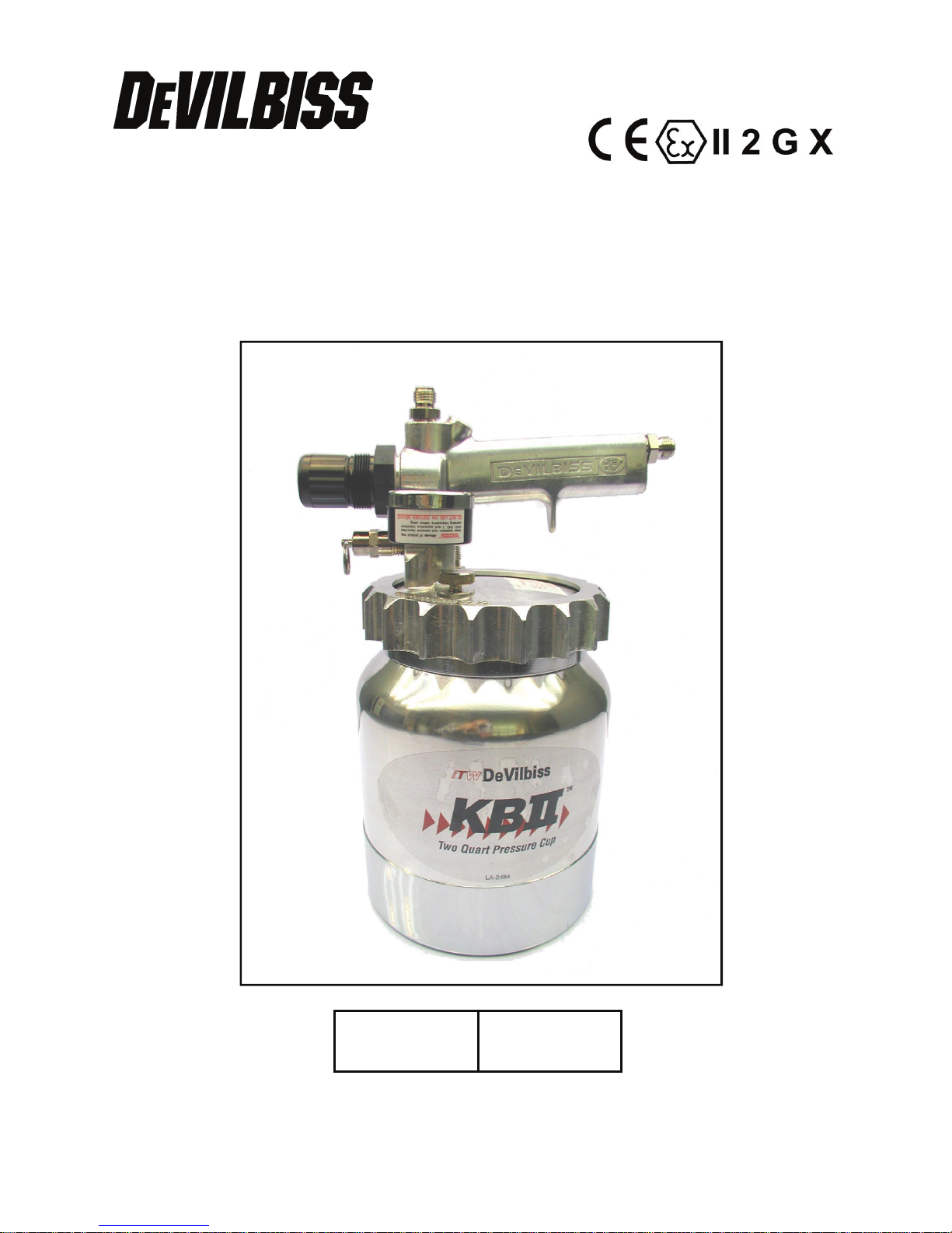
KB-522 & KB-522-SS
Pressure Feed Cup
ISS.02
E
E
P 1 - 12
© 2010 ITW Finishing Systems and Products
Page 2
EE
Operation Manual:
KB-522 & KB-522-SS Pressure Feed Cups
Important: Read and follow all instructions and SAFETY PRECAUTIONS
before using this equipment.
The KB-522 pressure feed cup incorporates an air regulator, safety valve, pressure relief
valve, pressure gauge and a carrying handle. An additional bail handle is also supplied to
enable the user to suspend the cup from a belt or other device. Hose assemblies to
connect the spray gun to the cup are not included and should be ordered separately, see
‘Accessories’.
Corrosion resistant version also available with Stainless Steel Cup and plated Lid.
Order No.
KB-522 STD CUP
KB-522-SS STAINLESS STEEL CUP
EC Declaration of Conformity
We: ITW Finishing UK, Ringwood Rd, Bournemouth, Dorset, BH11 9LH, UK, as the
manufacturer of the
Pressure Cup models KB-522 & KB-522-SS
declare, under our sole responsibility, that the equipment to which this document relates
is in conformity with the following standards or other normative documents:
EN 13463-1:2001; and thereby conform to the protection requirements of Council
Directive 94/9/EC relating to Equipment and Protective Systems intended for use in
Potentially Explosive Atmospheres protection level II 2 G X, suitable for use in ZONE
1 hazardous areas.
© 2010 ITW Finishing Systems and Products
B. Holt, General Manager
9th February 2004
2
Page 3
SAFETY WARNINGS
EE
Fire and explosion
Solvents and coating materials can
be highly flammable or combustible
when sprayed. ALWAYS
material suppliers instructions and COSHH
sheets before using this equipment
Users must comply with all local
and national codes of practice and
insurance company requirements
governing ventilation, fire
precautions, operation and house-keeping of
working areas
FOR KB-522 ONLY:
Do not use Solvents or coating
materials containing
HALOGENATED HYDROCARBONS with this
equipment.
FOR KB-522-SS ONLY:
This equipment, as supplied, is suitable for
use with Halogenated Hydrocarbons and the
user must ensure that all other equipment in
the system is also suitable for use with these
materials. DO NOT SPRAY MATERIALS
CONTAINING THESE SOLVENTS EXCEPT
WITH EQUIPMENT SPECIFICALLY
DESIGNATED BY THE MANUFACTURER
AS BEING SUITABLE FOR SUCH USE.
Static Electricity can be generated
by fluid and/or air passing through
hoses, by the spraying process
and by cleaning non- conductive
parts with cloths. To prevent ignition sources
from static discharges, earth continuity must
be maintained to the spraygun and other
metallic equipment used. It is essential to use
conductive air and/or fluid hoses.
refer to the coating
Personal Protective
Equipment
Toxic vapours – When sprayed,
certain materials may be
poisonous, create irritation or be
otherwise harmful to health.
Always read all labels and safety
data sheets for the material before
spraying and follow any recommendations. If
In Doubt, Contact Your Material Supplier
The use of respiratory protective
equipment is recommended at all
times. The type of equipment must be
compatible with the material being sprayed.
Always wear eye protection when
spraying or cleaning the spraygun
Gloves must be worn when spraying
or cleaning the equipment
Training
Personnel should be given adequate training
in the safe use of spraying equipment.
Misuse
Never aim a spraygun at any part of the
body. Never exceed the max. recommended
safe working pressure for the equipment.
The fitting of non-recommended or non-
original spares may create hazards.
Before cleaning or maintenance, all
pressure must be isolated and relieved from
the equipment.
Never exceed the recommended safe
working pressures for any of the equipment
used.
Never drill into or modify the pressure feed
cup in any way.
Do not adjust, remove or tamper with the
safety valve. If a replacement is necessary,
only use DeVilbiss supplied spare Valves.
The materials used in the construction of the
cup are (bearing in mind the warning on
Halogenated Hydrocarbons) solvent
resistant enabling the cup to be cleaned
using gun washing machines. However, the
lid assembly must not be cleaned in a gun
washing machine as it contains parts that
will be damaged.
3
© 2010 ITW Finishing Systems and Products
Page 4
EE
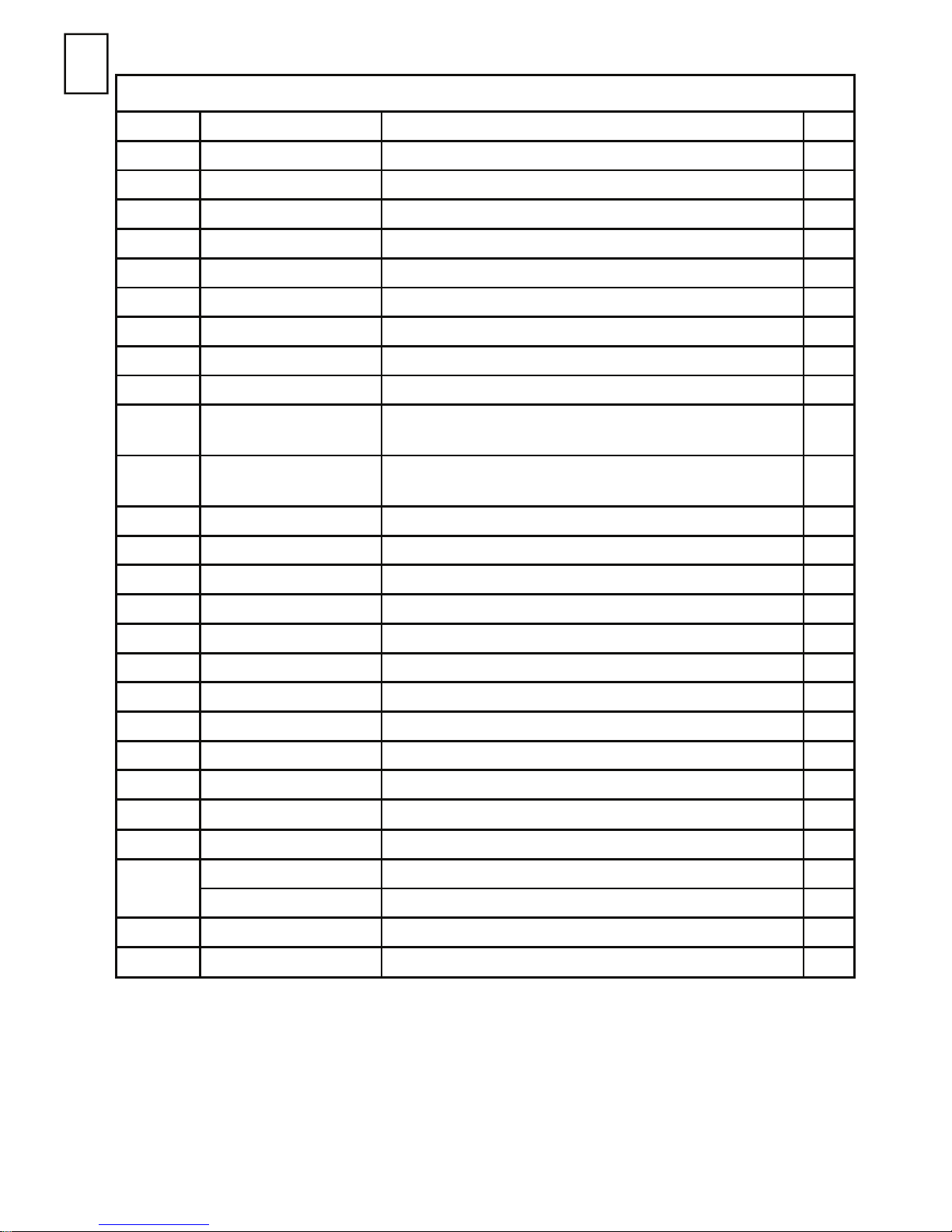
Parts List
Ref. Order No. Description Qty.
1 KB-64 Retaining Ring 1
2 KB-81-K5 Slip Rings 1
3 KB-74 Handle 1
4 SS-656-CD CD Nut 1
5 JGA-158 Connector 1/4" BSP 2
6 KB-66 Pressure Relief Valve 1
7 - Lid 1
8 GA-355 Gauge 1
9 KB-80-K5 Seal 1
10 MBD-11-K5
KB-97-K2
11 KB-422
KB-442
12 KB-432-K3 Check Valve kit of 3 1
13 KB-85-K5 Seal kit of 5 1
14 TIA-4355 Safety Valve 1
15 KB-428-1 Regulator Assembly 1
*16
*17
*18
*19
*20
21 - Spring 1
*22
23 KB-60-K6 Seal kit of 6 1
- Spring 1
- Valve 1
- Valve Seat and Seal
- Diaphragm 1
- Slip Ring 1
- Bonnet 1
Locknut (KB-522) kit of 5
Locknut -Stainless Steel (KB-522-SS) kit of 2
Cup – Aluminium (KB-522)
Cup – Stainless Steel (KB-522-SS)
1
1
1
24
KK-4997 Tube Assembly (KB-522) 1
KK-4996 Tube Assembly (KB-522-SS) 1
25 KB-444 Check Valve and Seal Assembly 1
26 KB-101-K5 Seal kit of 5 1
Note: Ref No.s marked * are supplied in repair kit Order No. KK-4887-2.
© 2010 ITW Finishing Systems and Products
4
Page 5

View showing position of internal
check valve parts
Fig 1
EE
Fig 2
5
© 2010 ITW Finishing Systems and Products
Page 6

EE
Specification
Hose connections
Air : 1/4" Universal
Fluid : 3/8" Universal
Maximum Working Pressure : 2.1 Bar (30 lbf/in2)
Maximum Air supply pressure : 8.6 Bar (125 lbf/in2)
Height : 183 mm (7 3/16")
Weight (dry) : 1.76 kg (3 lb 14 oz)
Capacity : 2 Litres
PARTS IN CONTACT WITH COATING MATERIAL:
522 522-SS
Cup : Aluminium Alloy Stainless Steel
Cup Lid : Aluminium Alloy Aluminium Alloy Nickel Plated
Lid Seal : Santoprene Santoprene
Tube : Aluminium Alloy Stainless Steel
Tube Nut : Brass Nickel Plated Stainless Steel
Check Valves : Acetal, Brass and S.S Acetal, Brass and S.S
Pressure Relief Valve : Brass Nickel Plated Brass Nickel Plated
Installation
IMPORTANT: To ensure that this equipment
reaches you in first class condition, protective
coatings, rust inhibitors, etc., have been used.
Flush all equipment through with a suitable
solvent before use to remove these agents from
the material passages.
Operation
CAUTION: The cup is under pressure.
Disconnect the air supply and release the
pressure in the cup assembly before removing
the cup from the lid assembly or disconnecting
the gun or the material hose. Never allow the cup
to lay on its side or fall over when it contains
material.
Controls (See Figure 1)
Safety Valve (14): The safety valve limits the
maximum air pressure to the cup. If the
safety valve does not work properly, over
pressurisation may occur and cause the cup
to rupture or explode. Occasionally pull the
ring on the safety valve and make sure that it
operates freely. If the valve is stuck or does
not operate smoothly it must be replaced
with a valve having the same rating. Never
attempt to adjust or dismantle the safety
valve.
Regulator (15): Controls the pressure of the
coating material in the cup. To increase the
1. Connect the coating material hose (Fig 2, A)
from the cup outlet to the gun.
2. Connect the air hose (B) from the cup outlet
to the gun.
3. Connect the air supply hose (C) to a filtered/
regulated air supply and to the cup inlet.
pressure, pull knob out, turn the knob in the
direction of the arrow shown on the knob, to
reduce pressure turn in the opposite direction.
When pressure is set push knob in to lock.
Pressure Relief Valve (6): Vents the air
pressure in the cup. To open, turn valve
counter-clockwise. CAUTION Do not
unscrew the pressure relief valve (6)
completely when relieving the pressure as it
may have sufficient air pressure to eject the
valve from the lid creating a hazard.
Pressure Gauge (8): Indicates the air
pressure in the cup. Do not attempt to
remove the cup (15), spray gun or coating
material hose if the gauge indicates pressure
in the cup.
NOTE: Regularly check that the pressure gauge
is reading correctly.
1. Mix, prepare and filter the coating material to
be sprayed according to the manufacturer’s
instructions.
© 2010 ITW Finishing Systems and Products
6
Page 7

EE
2. Adjust the spray gun controls as described in
the Operation Manual supplied with the gun.
3. Turn the regulator knob (15) to the minimum
pressure and open the pressure relief valve
(6) to vent any pressure in the cup.
4. Remove cup (11) by turning ring (1) counterclockwise and fill with the coating material,
DO NOT OVERFILL. (If using the liner Kit KK
-5051, see section on liner fitting)
5. Replace lid assembly on cup, push down
with the handle and tighten ring (1).
6. Close the pressure relief valve (6), turn on
Preventative Maintenance
CLEANING
DO NOT clean the cup lid assembly in a gun
washing machine as the safety valve (18), gauge
(6) and regulator (19) contain parts that will be
damaged.
1. Disconnect the air supply and relieve the
pressure in the cup.
2. Remove the cup (11) and empty surplus
coating material. Wipe the lid and the inside
of the cup clean.
3. Fill the cup with a small quantity of compatible solvent and refit. Connect the air supply,
and adjust the supply air pressure to 3.5 bar
(50 lbf/in2).
7. Adjust the material pressure to 0.7 bar (10
lbf/in2).
8. Test spray, adjust atomisation and material
pressures to suit required application rate.
NOTE: To reduce the material pressure turn
regulator (15) down and open the pressure relief
valve (6). Close relief valve (6), and readjust the
regulator (15).
spray the solvent until clean.
4. Disconnect the air supply and relieve the
pressure in the cup.
5. Remove the cup (11), empty the residual
solvent and dry internal surfaces.
6. Inspect that the check valve (12) and pressure relief vent holes in the lid are free from
coating material.
NOTE: The check valve cap may be unscrewed
to aid inspection and cleaning, DO NOT dismantle any further.
CONDITION CAUSE CORRECTION
Erratic regulation or
A
excess pressure in the cup
3 Safety valve (14) faulty Replace
4 Regulator Spring (21) broken or
5 Regulator diaphragm (19) damaged Replace
Insufficient pressure in the
B
cup
3 Gauge (8) reading incorrectly Replace
4 Air leakage at cup lid Tighten ring (1), replace
Service Checks
1 Regulator valve (17, 18) leak Replace
2 Gauge (8) reading incorrectly Replace
Replace
distorted
1 Check valve (12) jammed. Clean/replace.
2 Safety valve faulty. Replace
Seal (9) or Slip Ring (2)
7
© 2010 ITW Finishing Systems and Products
Page 8

EE
KK-5051 DISPOSABLE CUP LINER
The DeVilbiss Liner system creates a barrier between the coating material and the cup,
avoiding lengthy cleaning procedures and saving solvent. The liner can be used with any
coating material that is compatible with polyethylene.
Each kit consists of 20 Liners, 20 Lids and 3 Rings
Installation Instructions
Liner Kit Parts
Ring
Disposable
Lid
Liner
Insert Liner
Into Cup
Disposable Lid
Fill liner with
Coating Material
Insert Lid
Wrap Liner
Over Lid
© 2010 ITW Finishing Systems and Products
8
Page 9

EE
Place Ring
Inside Cup
Ring
Slide Fluid Tube
through opening
and assemble Lid
to cup
Disassembly/Cleaning Instructions
Disassemble Cup Lid.
Withdraw the tube slowly to allow
the paint inside the tube to drain.
Catch excess paint with rag.
9
© 2010 ITW Finishing Systems and Products
Page 10

EE
Remove Ring
Properly Dispose of Lid,
Liner and waste material.
Retrieve Ring
Pull up on Liner
© 2010 ITW Finishing Systems and Products
10
Page 11

NOTES
11
© 2010 ITW Finishing Systems and Products
Page 12

EE
Accessories
Hose Assemblies to connect cup to spraygun:
Order No. H-.6066-N Air hose 8 mm bore 1.2 m long with 1/4” connections
H-6067-N Coating material hose 6 mm bore 1.4 m long with 3/8”
connections.
Other accessories;
Order No. KB-435 Conversion Kit for 50 psi maximum working pressures version.
KK-5051 Liner Kit of 20 Liners
ITW Finishing Systems and Products
Ringwood Road,
Bournemouth,
BH11 9LH,
England.
Tel. No. (01202) 571111
Telefax No. (01202) 581940,
Website address http://www.itweuropeanfinishing.com
ITW Finishing Systems and Products is a Division of ITW Ltd. Reg. Office:
Admiral House,
St Leonard’s Road,
Windsor,
Berkshire,
SL4 3BL,
UK
Registered in England: No 559693 Vat No 619 5461 24
© 2010 ITW Finishing Systems and Products
12
August 10
 Loading...