

Page 1
1
JUPITER-K GUN Operation Manual
For GENERAL INDUSTRIES
IMPORTANT:Read and follow all instructions and SAFETY PRECAUTIONS
before using this equipment.
The gun body of this model is finished with special coati ng. Do not use wire-brush or metal-spatula
for cleaning. Do not inscribe letters on the gun body. It may cause the coating to peel off.
MODELS
JUPITER-K – Air Cap №
– Fluid Tip Size – Type of Feed (P:Pressure)
(Ex.): JUPITER
-K–P1–FX–P ← (№P1 Air Cap – Size FX (1.1mm) – Pressure)
SPECIFICATIONS
Maximum Working Air Pressure: 0.69 MPa, Maximum Working Fluid Pressure: 0.69 MPa
Chart.1
Air cap №
Part Number
Tip Size(mm)
Type
Air
Consumption
Air Inlet
Pressure
Pattern
Range
(mm)
Applications Fluid Inlet Air Inlet
Weight
(g)
FX(1.1) FF(1.4)
P1
JUP-3-P1
○ ○
Pressure
LVMP
200L/min
0.2MPa
250mm
Automotives &
General Industries
G3/8 G1/4 348g
P2
JUP-3-P2
○ ○
Pressure
LVMP
200L/min
0.2MPa
300mm
P3
JUP-3-P3
○ ○
Pressure
Conventional
550L/min
0.24MPa
400mm
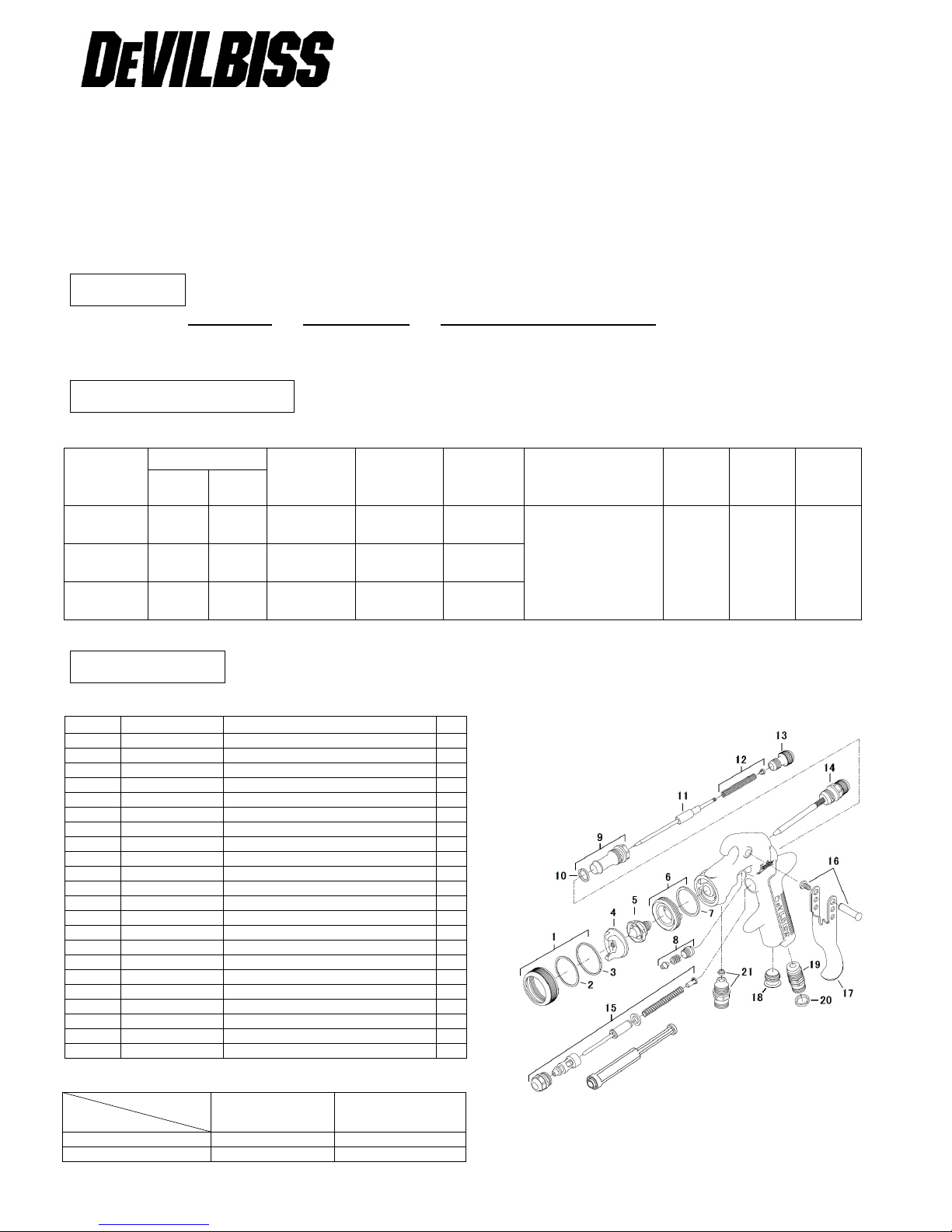
PARTS LIST
Chart.2
Chart.3
Ref. №
Part Number
Description
Qty
1
JUP-6
Retaining Ring
1 2 JUP-50-K5
Cap Seat
1
3
JUP-55-K5
Ring Seat
1
4
Refer Chart.1
Air Cap 1 5
Refer Chart.3
Fluid Tip 1 6
JUP-7
Baffle 1 7
JUP-8-K5
Gasket 1 8
SN-404-K
Packing, Spring & Packing Nut Kit
1 9 JUP-12
Body Bushing & Seal
1
10
JUP-72-K5
Body Bushing Gasket
1
11
Refer Chart 3
Needle 1 12
SN-409
Valve Spring and Pad Kit
1
13
JUP-13-K
Needle Adjusting Knob
1
14
JUP-44-K
Pattern Valve Asse mbly
1
15
JUP-43
Air Valve Assembl y
1
16
SN-405-J-K5
Trigger Stud & Hex Screw
1
17
JUP-108
Trigger 1 18
JUP-21
Plug 1 19
JUP-30
Air Connector
1
20
SN-26-K4
Color ID Ring Kit (sold separately)
1
21
JUP-35P
Fluid Inlet (Pressure)
1
Description
Size (mm)
Fluid Tip Needle
FX(1.1)
JUP-4-FX-S
JUP-41-FZ
FF(1.4)
JUP-4-FF-S
JUP-41-FZ
Page 2
2
SAFETY PRECAUTIONS
This manual contains information that is important for you to know and understand.
This information relates to USER SAFETY and PREVENTING EQUIPMENT PROBLEMS.
Read and follow SAFETY PRECAUTIONS before using this equipment.
FIRE OR EXPLOSION HAZARD
1. When spraying, adequate exhaust must be provided to keep air free of accumulations of flammable vapors which may
cause fire or explosion.
2. Smoking must never be allowed in the spray area.
3. Static electricity is generated and a static spark could be produced in the spray area. To prevent the risk of fire or
explosion, ground all conductive objects in the spray area.
4. Make it sure to use and ground hoses with static wire for spray gun operation. If improperly grounded, a static spark
possibly produced may cause fire or explosion.
5. Fire extinguishing equipment must be provided in the spray area.
6. Solvents used for cleaning must have a flash point equal to or higher than that of the coating. Those for general
cleaning must have flash points above 37.8℃(100°F) to prevent the risk of fire.
INHALING TOXIC SUBSTANCES
1. Toxic vapors and liquids are harmful to health. When spraying, adequate exhaust must be provided to keep the air
free from accumulations of toxic materials and in the use at all times of respiratory protective equipment must be set
compulsory.
2. Always wear eye protection when spraying or cleaning the equipment.
3. Certain materials may be harmful if contacted with the skin. Read all labels and safety performance data of the
materials and solvents to be used. Appropriate clothes and gloves must be worn for spraying or cleaning the
equipment.
MISUSE
1. Operators should be given adequate and appropriate training in the safe use and maintenance of this equipment.
2. Pressured liquids may injure eyes. Do not point the spray gun to any person.
3. Gravity or suction feed gun must not be used for pressure feed gun.
4. Parts with compressed air may damage the human body. Connect air hoses tightly by using a spanner so that air
never leaks. If tightened loosely, hoses can be removed which may result in damaging the human body, objects to be
coated and other equipment used together.
5. Parts with compressed air or under spring pressure may injure the human body. When replacing such parts, clean the
spray gun by discharging the materials, discharge the air, remove air hose and fluid cup and then replace such parts by
placing the gun flat. Eye protection must be worn when repairing the spray gun.
6. Do not use the gun above maximum working pressure (0.69MPa).
INSTALLATION
1. The air supplied to spray gun must be clean, in which any water, oil and solid material removed. It is recommended to
set up the Mist Separator and A ir Transformer near the gun. The use of air not cleaned may cause coating troubles.
2. Connect fluid cup and air hoses tightly. If loose, hoses may disconnect, which may result in damaging the human body,
objects to be coated and other equipments used together.
3. Adjust Needle Packing (8) before use of a brand new gun. Tighten the Packing Gland (8) gradually and adjust the
needle to move smoothly. Untighten until the Needle (11) is not well pulled back.
OPERATION
1. The recommended pressure of air supplied to gun is in a range of 0.24MPa~0.30MPa for conventional type, and
0.19MPa~0.29MPa for LVMP type. Do not exceed the maximum working air pressure for proper usage (0.69MPa).
2. Try with the pressure starting from around 0.2MPa, as the spraying pressure varies depending upon the inner diameter
of gun, triggering distance, and materials etc.
3. The recommended spraying distance is 180mm. If the spray distance is too far, good result will not appear.
4. In order to get uniform finishing, the spray gun should be held vertically toward the painting surface.
Page 3

3
PREVENTIVE MAINTENANCE
1. Daily lubrication and cleaning is necessary to maintain the best condition of the gun.
2. To clean the gun body, wipe exterior with solvent dampened cloth. Do not submerge the gun body in solvent as any
solids may get into the air passage causing troubles.
3. Do not leave the gun with solvent remained in the fluid cup. Clean the spray gun after use with clean solvent and by
emptying the cup. To clean the fluid cup after use, remove remaining paint through appropriate solvent and flush down
the residual paint.
4. The Air Cap can be immersed in solvent and brushed down for cleaning. If orifices are clogged, use a toothpick to
remove obstruction. Never use a steel wire or hard instrument. This will damage air cap and result in a distorted
spray pattern.
5. Do not immerse any plastic parts in solvent for long time.
6. Certain portions of gun should be lubricated. Do not lubricate to any portion where not instructed. For lubrication,
SSL-10 Gun Lube* is recommended (*sold separately, vegetable oil that does not repel paint materials).
7. The following portions should be lubricated regularly; Trigger Bearing Stud Screw (16), Pattern Valve (14), and Adjusting
Screw (13), Air Valve Stem (15), and portion of Packing Gland (8) where Needle (11) comes in and out.
8. When installing Air Cap (4), make sure no foreign materials adhered on Retaining Ring (1) and thread of Baffle (6).
Inject one drop of Gun Lube SSL-10.
9. Apply non-silicone grease lightly on Needle Spring (12) and Air Valve Spring (15). Do not apply too much grease as it
may clog the air passage.
REPLACEMENT OF PARTS
Before replacing gun parts, remove materials from the gun for cleaning. Then relea s e the air pre s sure in the gun and
disconnect air hoses. All repairs should be made on a clean flat surface. Use only appropriate tools indicated for
replacement of parts.
Fluid Tip (5) and Needle (11)
1. It is recommended to replace Fluid Tip (5) and Needle (11) as a set.
2. Loosen Pattern Valve (14) completely by turning the knob counterclockwise.
3. Remove Adjusting Screw (13) and Needle Spring (12) and then withdraw Needle (11) from the gun body.
4. Remove Retaining Ring (1) and Air Cap (4).
5. Remove Fluid Tip (5) by using socket wrench or offset wrench and Baffle (6) can also be removed.
6. Recommended torque of Fluid Tip (5) is 8N・m.
Fluid Inlet (21) and A ir Connector (19)
Fluid Inlet (21) and Air Connector (19) are fixed together by sealing material. Do not disassemble these connectors if it
is not necessary.
Pattern Valve (14)
When disassembling and reassembling Pattern Valve ( 14 ) , turn the knob completely counterclockwise and then
disassemble or reassemble them.
Air Valve Assembly (15)
Valve Seal Replacing Tool is required for re placing Valve Seal (15) and it is provided when you purchase Air Valve
Assembly (15). When replacing Air Valve, be careful not to damage the surfac e of se al s of Gun Body, and Air Valve
to prevent air leakage.
1. Using Hexagon Wrench 2.5mm (from the market) for removing the Trigger Screw (16) and then remove Trigger (17).
2. Remove Air Valv e Assembly (15) by using 14mm offset wrench.
3. Withdraw Valve Spring from spring pad.
4. Withdraw Valve Rear Seal, using the Valve Seal Replacing Tool. Disassembling of Air Valve is now completed.
5. The next is assembling. Insert and place the Valve Seal at the end of valve hole of gun body by using Replacing Tool.
6. Insert new spring, ensuring the end with the plastic bearing pad goes in first.
7. Insert Air Valve Assembly (15) into gun.
8. Tighten Air Valve Assembly using fingers first and then tighten with offset wrench 14mm which is available in the market.
9. Replace Trigger (17) using Hexagon Wrench 2.5mm.
Needle Packing (8)
1. Using Hexagon Wrench 2.5mm (from the market) for removing the Trigger Screw (16) and then remove Trigger (17).
2. Remove Fluid Adjusting Knob(13) and Needle Spring with Spring Pad(12) from gun, and then remove Fluid Needle(11) .
3. Loosen and remove Packing Nut (8) using a straight blade screw driver.
4. Reassembling the Packing (8). Assemble into gun body by hand and then tighten using a screwdriver.
5. Insert Fluid Needle (11), and then Needle Spring with Pad (12), and Needle Adjusting Knob (13). Reinstall Trigger (17).
6. Trigger gun several times to verify correct operation.
Page 4

4
SERVICE CHECKS
Problem
Cause
Correction
Will not spray
No pressure to gun.
Adjusting Screw (13) not properly adjusted.
Check air and material lines.
Adjust.
Improper spray pattern
A,B - Material build up on the Air Cap or Fluid Tip.
C,D - Incorrect fluid delivery or viscosity.
A,B - Clean the Air Cap or Fluid Tip.
C,D - Adjust.
Jerky or fluttering spray
Insufficient material in the cup or loose Connector.
Gun fluid passage plugged.
Worn Needle Packing (8).
Loose or damaged Fluid Tip (5).
Fill cup or tighten the Connector.
Clean.
Replace.
Tighten or replace.
Fluid leaking from
Needle Packing Nut (8)
Worn or damaged Needle Packing (8).
Replace.
Dripping from Fluid Tip
Worn or damaged Fluid Tip (5) or Needle (11).
Stuck Needle Packing (8) or Needle (11).
Loose Adjusting Screw (13).
Replace.
Lubricate.
Adjust.
ACCESSORIES
Part №
Description
Part №
Description
42884-214-K5 Cleaning Brush (kit of 5) SSL-10 Gun Lube (60ml)
SN-26-K4 Color ID Ring Kit (4 colors)
D E VILBISS DIVISION
RANSBURG INDUSTRIAL FINISHING KK
15-5 Fuku-ura 1Chome,Kanazawa-ku,Yokohama,Kanagawa,Japan 〒236-0004
℡ 045- 785- 6371 Fax045- 785- 6517
 Loading...