

Page 1
DEVILBISS
SERVICE
BULLETIN
SB-2-240-C
Replaces
SB-2-240-B
AUTOMOnYE
REFINISHING
PIIODUCiS
Repair
Kil
KK-4987-1
JGHV-530 High Volume
Low Pressure Spray Gun
IMPORTANT:
Before
using
this
equipment,
read all
safety
precautions
and
Instructions.
Retain
lor
fu-
ture
use.
DESCRIPTION
The JGHV-530 is a primary, auto refinish HVLP spray
gun designed to apply a wide variety of finishing
materi-
als. This gun was manufactured to comply
with
SCAQMD
and
other
air
quality
authorities
by limiting the air cap
pressure to
10 psi. This spray gun is intended for use
with pressure feed paint supply only.
The No. 33 air cap and gun is intended for
small
or
partial
jobs. The No. 57 air cap and gun is intended for larger
jobs, completes and fleet refinishing jobs. Refer to the
Air Cap Chart 2
lor
more information.
INSTALLATION
Connect the gun to a clean, moisture and oil tree air
supply using a hose size of at least
5/16"
I.D
. Depending
on hose length, larger
I.
D.
may be required. Install an air
adjusting valve/air gauge,
HAV-501, at the gun handle
and air cap test kit,see
"Accessories", over tip.
For
maximum
gun
pertonmance and
to
assure
code
compliance,
set
the
air
cap
presssure
at10
pslg
or
less. Remove the air cap test kit and install the air cap.
OPERATION
Adjust fluid pressure to deliver the desired paint volume.
As a general rule of thumb, the
following fluid flow and tip
sizes should be
followed.
Tip
Cap
Size
Flow (oz /min.)
DFX
57
.042 10-14
FX
33
.042"
10
GX
33
.034'
6
Excessive flow rates will resutt
in
heavy center spray
patterns.
Inadequate flows may cause the pattern to
split.
See Spray Gun Guide, SB-2-001, for details
concerning set up of spray guns.
HVLP requires gun distances of
6-8" be used. Excess
distance
will produce inferior results.
Strain material thru
60
or
90 mesh screen.
Best atomization
will occur with 10 psig air cap pressure.
However, some materials can be sprayed
at
lower pres-
sures which will result in higher transfer efficiency.
PREVENTIVE
MAINTENANCE
To clean fluid passages, remove excess material at
source, then flush with a suitable solvent.
To clean air cap and
fluid tip, brush exterior wtth a stiff
bristle brush.
If
necessary to clean cap holes, use a
broom straw
or
toothpick.
Never
use a wire
or
hard
Instrument.
This
may
scratch
or
burr holes causing a
distorted spray pattern.
Wipe gun exterior with a solvent dampened cloth. Never
completely immerse in solvent
as
this is detrimental to
the performance and gun
life expectancy, as well
as
destroying the lubricants and packings.
Note
When baffle (6) & fluid
tip
(3) are removed, seal
(4)
and
0-Ring
(27) should
be
replaced. For your convenience,
an extra seal
&
0-Ring
is included wtth this gun.
Be
sure
to
lubricate the
ID
of the baffle and
0-Ring
with SSL-10
gun lube to prevent
0-Ring
damage during installation.
Spray
Gun
Lubrication
Daily, apply a drop of gun lube
at
trigger bearing stud (19)
and the stem
of
the air valve (14) where it enters the
a1r
valve assembly (17). The shank
of
the fluid needle (29)
where
it
enters the packing nut (23) should also
be
oiled.
The fluid needle packing (22) should
be
kept soft and
pliable by periodic lubrication. Make
sure
baffle and
retaining
ring
threads
are
clean
and
tree
of
foreign
matter.
Before
assembling
air
cap
to
baffle, add
one
drop
of
gun
lube
to
threads.
The fluid needle spring (31) should be coated with a light
grease. The air valve spring (15) should be coated with
a very light grease, ensuring that any excess grease
will
not clog the air passages.
For
best results, lubricate the
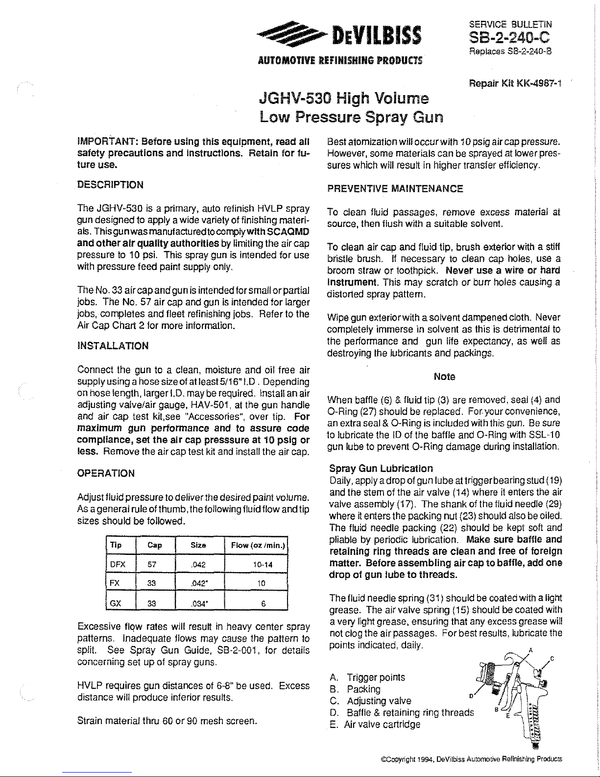
points indicated, daily.
A. Trigger points
B. Packing
C.
Adjusting valve
D
D.
Baffle & retaining ring threads
E.
Air valve cartridge
©Copyright
1994,
DeVilbiss
Automotive
Refinishing
Products
Page 2
Page 2 SB-2-240-C
CHART1
1 AIR CAP/TIP APPLICATIONS
-
I
Air
I
Max. Inlet
I
*Pattern I Typical
Gun Model Cap Tip
Pressure
Size
Application
JGHV -530-33GX #33
GX
(.034) 80 7-8" Thin Materials, Base Coats, I
Small/partial
jobs
JGHV -530-33FX
I #33
I
FX
(.042)
80
I
8-9" SmaiVpartial jobs, General
Puroose Base/Clear
JGHV-530-57DFX #57
I
FX
(.042)
65
1 0-12"
Larger jobs, High Flow
Rates. Fleet Refinishino
.
Actual pattern
SIZe
depends upon matenal bemg sprayed,
flUid
flow rate,
a1r
pressure
and
fan
oressure.
CHART2
AIR CAP.& BAFFLE COMBINATIONS
No.Stamped
on Parts
I
Set
I
Air Cap
Ref.
No.2
I
Ref.
No.6
c;FM_';9'
10PSI
Size Baffle
Air
Cap Baffle Cap
33
33-80
JGHV-t01-33
I :GHV-450-33-80
18.5
57 57-65
JGHV-101-57 JGHV-450-57-65
21.0
CHART3
I FLUID TIPS AND NEEDLES
If this
is
No.
on
*Ret
#3
Fluid
Tip
Ref. No. 29
Tip
Order#
Gasket
Assy
Fld. Needle No
on
Needle
AV-2115-FX AV-650-FX JGA-402-FX
AV-2115-GX
AV-650-GX
JGA-402-GX
AV-2125-DFX
--
--
:j:Do
not
use
AV-1
Gasket
w1th
this
gun.
!
CAUTION
J
Order
No
Lapped
Sets
JGA-4040-FX
JGA-4040-GX
JGA-4046-t1
To prevent damage
to
the
fluid
tip
(3)
or
fluid
needle (29), be
sure
to
either
1)
pull
the
trigger
and
hold
while
tightening
the
fluid
lip
or
2)
remove
fluid
needle
adjusting
screw
to
re-
lieve
spring
pressure.
l
CAUTION
]
To avoid
serious
gun
damage,
do
not
remove
the
fluid
tip
(3) from the
spray
gun
when
the
fluid
inlet
adapter
(9)
is
removed. Doing
so
may
allow
the
stainless
steel
insert
to
break
tree
from
the
aluminum
body,
which
is
non-
repairable.
JGHV-116-KS Gasket Replacement
Instructions
1.
Remove fluid inlet adapter
(9)
with appropriate tool.
2. Clean loctite from gun body inlet threads and seat
area.
3.
Place gasket
(7)
squarely into the fluid inlet cavity in
the gun body. Push the gasket
(7)
down with a blunt
object, such
as
a pen or pencil,
to
guide and seat the
gasket squarely into the gun body.
4.
Place a couple of drops of QH-130 (medium strength
blue No. 242 Loctite)
on
threads before installing fluid
inlet adapter (9).
5.
Torque fluid inlet adapter to 10 II. lbs.
and
tighten
locknut (8).
PARTS UST
Ref.
Replacement
Individual
No. Part No. Descriotion
Parts ReQ.
t
MBC-368
Retaining
Ring
for
Ref.
No.
2 t
2
See Chart 1
Air
c¥;
1
3 See
Chart3
Fluid ip
1
4
JGD-14-K10
Seal (Kit of 10( (Polyethylene)
1
5
SSG-8182-K5
·o· Ring (l<it o 5)
1
6
See Chart 2 Baffle, asket & Seal Kit
1
7
JGHV-t16-K5 Gasket (Kit
of
5) Glass filled Teflon) 1
B
-
Locknut
1
9
-
Fluid Inlet Adapter 3/8" NPS
1
10 JGV-444
Fluid Inlet, Nut & Gasket
Kit
1
•1t
-
Snap Ring 1
•12
-
Washer
1
·13
-
·u·
Cup 1
•14
-
Air
Valve
t
•15
-
Spring
1
•t6
JGS-72-K10 Gasket (Kit of
tO~
(Teflon)
2
#t7
JGS-449-1
Air
Valve
Assem
ly
1
•18
-
Screw
1
19
-
T
rig3er
BearinR-
Stud
1
I
20 JGS-478
Stu
& Screw
it
1
(Kit
includes
3
studs
& 5
screws}
21
JGS-477 Trigger, Stud & Screw Kit
1
I
~Kit
mcludes 1 each)
• 22
JGA-4035-KtO acking (Kit of 10) 1
I
23
344tt-122-K10
Fluid Needle Packing Nut (Kit of
tO)
t
24 JGA-132
Plu~
t
I
25
P-MB-St
Air nlet Adapter 1/4" NPS 1
I
•26
-
Retaining
Ring
1
• 27
-
·o·
Ring
(Vitron)
1
28
JGA-497-1
Fan
Adjustment
Assy.
1
I
29
See
Chart 3 Fluid Needle
t
I
30
-
Gun
Bod~
Bushing
t
·31
MBD-19-K10 Spring ( it of 10)
t
32
JGS-16
Fluid
Needle
Adjusting
Screw
1
33
JGA-4041
Bushing,
Spring & Knob
Kit
1
• A quantny of necessary parts
is
included
in
Gun Repair
Ktt
KK-4987-1 which should be kept on hand for service
convenience.
# Use JGS-449-1 valve assembly only.
Do
LlQt
use JGS-
449. Pressure drop will occur.
Note
All
wetted suriaces are stainless steel
and
may
be
used
with materials
formulated with chlorinated solvents.
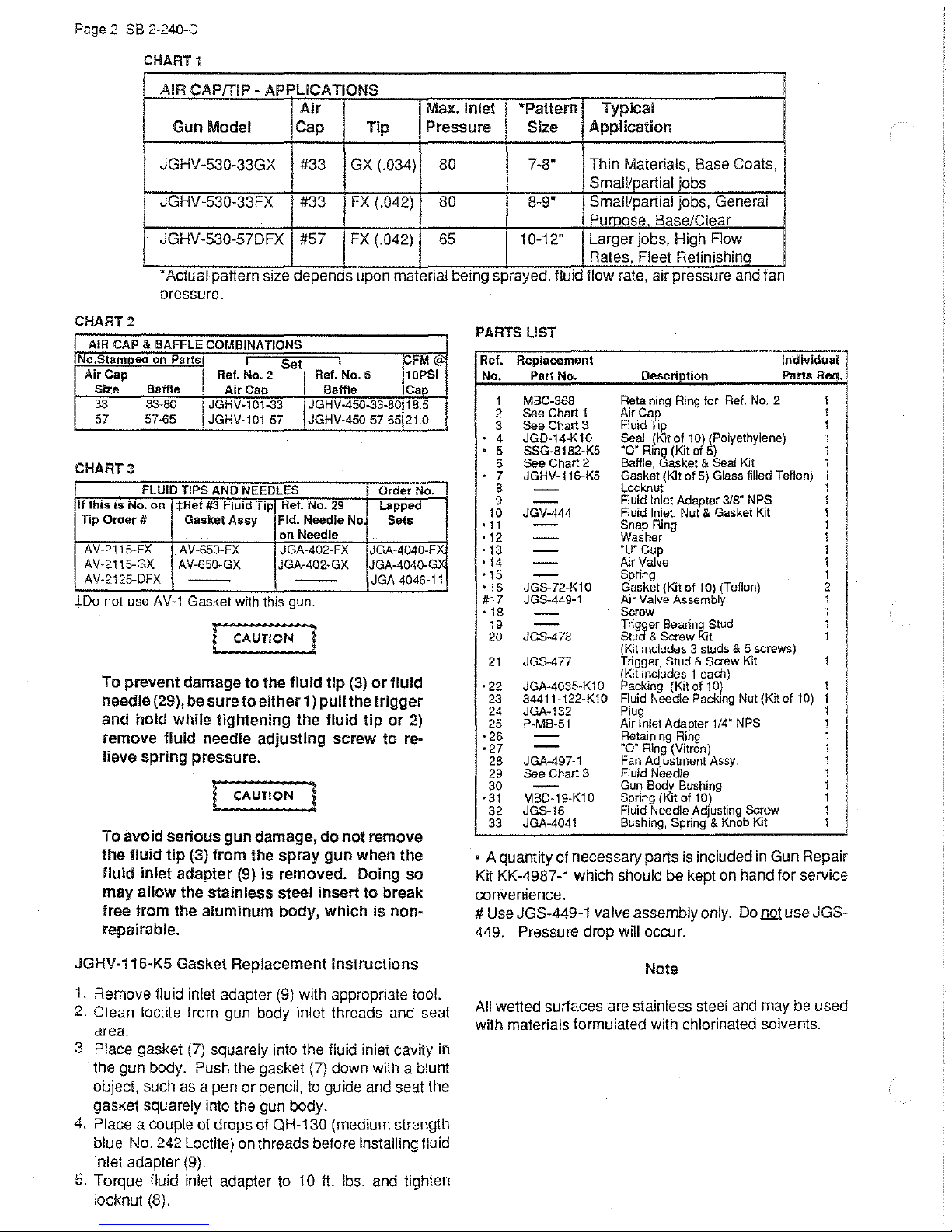
Page 3

29
\
21
17
SB-2-240-C
Page
3
33
I
_jl
__
_j
~
.&.
(Ref.
No.
22)
Needle Packing
Assy.
Detailed • Apply0H-130(Loctite#242med.strengthblue)sealing
t.1
3
Piece
Drawing
compound on threads.
Page 4

Page
4 SB-2-240-C
ACCESSORIES
KK-4978
lation
KK·4979
cups
KK-4980
or
TGC-429NewTetlonStyleCheck
or
42884·214-K5 (318") & 42884·215·K10 (5/8")
These brushes are helpful in cleaning threads and recesses
Adapter/Quick
of
a paint cup regulator.
Check
with
Cup
Regulator
Valve/Poppet
paint
cup
TSC-59t.
for use
TSC-590 cups for paint
TSC-590 and
Connect
Kit-
cup
Kit-
For JGHV-520 gun, for instal-
Kit-
regulator.
Converts TLC-575 and TSC-590
To convertJGHV-520 gun and TLC-575
pressure control.
Valve-
Use
with
TLC-575, TLC-576
Cleaning
Brushes-
body.
MSP~521
(TC-23C-863) for respiratory protection in atmospheres not
ately dangerous to life.
Twin
Cartridge,
Paint
Spray
Respirator-
NIOSH-Certified
of
gun
immedi-
HAV..S01
Adjusting
Vaive
Use to control air
at gun.
KS.S25 2
Qt
Preuure
Feed
Cup with
Regulator
usage
JGA~52-K10
?ackinga
Usually used when abra-
sive materials are
spra)'&d. Use (2) JGA-52
packmgs
inplaceofJGA-
4035
packlng.
II
SPRAYGUNLUBE
SSL~10
(2
o.z.botue)
I
I
I
l
~
~
Co~tibl&
matenats
COlle
latestocontamnate
Wllh
all
cornamsnos111-
or
petro~um
VS-531 Low
Pressure
Strainers
oatntl'
diStJI·I
pam.
I
KK-5004
painter
Pressure
to
convert spray gun into a suction feed type spray gun.
Feed
to
Suction
Feed
Conversion
Kit·
Allows a
WARRANTY
This product is covered by DeVilbiss' 1 Year Limited
Warranty. See SB-1-000 which
is
available upon re-
quest.
WORLDWIDE SALES AND SERVICE- DeVilbiss
has
DeVilbiss
"Automobile Body Shop Equipment
authorized distributors throughout the world. For equipment, parts
and
Supplies".
Distribuiion Centers or Sales Offices nearest you.
Automotive
If
further assistance
Provides graater
of control over cup lluid
pressure.
KK-4974-33 for
KK-4974-57
KK-4974--33,
KK..-\974-57
A!r
Cap
for
degree
Teat Kits
JGHV-101·33
&
JGHV-101·57
1 0!. pressure feed cups.
318•
NPS
lid. ReqUifas KK-4980 &
KK-4978.
,1{~
li!)'\WJ"'l
Measures
rur
SERVICE
For complete guide
Service Bulletin SB-2-001.
Refinishing Products
air
cap
pressure at
atom·lzing
the
air
cap.
NOTES
on
and
is
required, write or call one
service, check the Yellow Pages under
air spray equipment, order
(F},cam
m 1
The
VS-531
sure Fluid Strainer prcr
locked
of
vides a final
ping f()raign particles
the
Contains
tip,
used
the following DeVilbiss
filter
pamt
supply.
WR~103
all
hose
and
on
or
w1th
Low
Pras-~
tor
trap-
Wrench
necessary
nul
sizes
gun.
free
in
,
FOR
TECHNICAL ASSISTANCE, CALL TOLL FREE
BELOW.
U.S.
Sales & Customer Service
MAUMEE,
Canada Sales &
BARRIE, ONTARIO, <;:ANADA
INTERNATIONAL MARKETING AND
Mllperra, N.S.
Sao
OH
43537
W.
Paulo, Brasil
Customer
Service
L4M
6K1
IV'.ANUFACTURING
and Moorabbin, Vic. Australia
Bournemouth, England
Valence (Cedex), France
DeVilbiss Automotive
An
Maumee,
4/94
Refinishing
Ohio
43537
Co.
1·800·445-3988
(U.S.A. ONLY).
Address
1724 Indian Wood Circle, Suite G
P.
0.
Box 2300
IN
COUNTRIES LISTED BELOW
Dietzenbach, West Germany
Tokyo,
Tlalnepantla, Mexico
Products
Japan
DeVilbiss
A
Barrie,
FOR
LOCAL CALLS, SEE
Telephone Number
General Inquiry
Toll
Free Fax No. 1-800-445-6643
(419) 8g1-8100
General Inquiry (705) 728-5533
Fax
No. 705-721·5533
Spray
Div.
of Canada
Ontario,
Equipment
Canada
Inc.
L4M
6K
1
Printed in
liSTING
U.SA
 Loading...