

DeVilbiss JGA-510-98FX Service Manual
SERVICE MANUAL
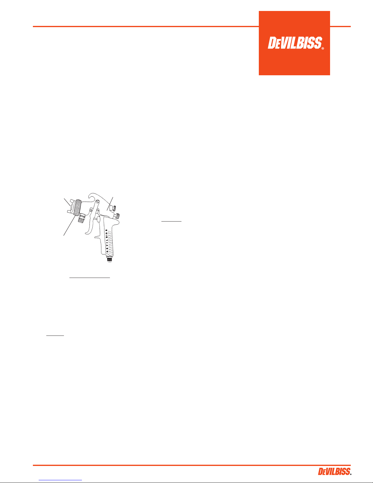
JGA-510-98FX
PRESSURE FEED HIGH VOLUME
LOW PRESSURE SPRAY GUN
Major Repair Kit KK-4987-2
Minor Repair Kit KK-5034
EN
IMPORTANT: Before using this
equipment, read all safety precautions and instructions. Keep for
future use.
MODEL NUMBER
JGA-510-98FX Full Size Gun Body
DESCRIPTION
Air Cap Stamped
98 HVLP
Baffle Stamped
Max. 30 PSI, 98
The JGA-HVLP pressure feed gun incorporates a LOW CFM HVLP air cap (#98)
which is capable of spraying a wide variety
of materials (low to medium solids), at
fluid flows typically in the 7 to 10 ounce/
minute range.
Air consumption for the #98 air cap is
approximately 11 SCFM @ 10 psi cap
pressure. Inlet air pressure of approximately 30 psi (measured at gun handle,
flowing) is required to achieve 10 psi cap
pressure. The actual air cap pressure can
be verified by using an air cap test kit (see
Accessories, page 6).
The gun model also includes a conversion air baffle, which converts the higher
incoming pressure to low pressure (HVLP).
All other components, with the exception
of the air cap and baffle, are identical to
other conventional air spray JGA-510
models.
This gun model includes 300 series stainless steel needles and 400 series fluid tips.
See page 3 for the 300 series tip and needle
which may be ordered separately. This
gun can be used with chlorinated solvent
materials, but see page 2 for additional
warnings.
Body Stamped
JGA-510
xxx-xxx
IMPORTANT: This gun may be used with
most common coating and finishing materials. It is designed for use with mildly
corrosive and non-abrasive materials. If
used with other high corrosive or abrasive materials, it must be expected that
frequent and thorough cleaning will be
required and the necessity for replacement
of parts will be increased.
INSTALLATION
Connect the spray gun to a clean, oil and
moisture free air supply. The air inlet
(located at the base of the gun handle)
includes a 1/4" NPS (M) connection.
Be sure to use hose with an ID of at least
5/16". DO NOT use 1/4" ID air hose which
is restrictive and will cause excessive
pressure drop (example - at 18 CFM, 25
ft. of 1/4" hose has a pressure loss of 25
psi, but 25 ft. of 5/16" hose at 18 CFM has
a pressure loss of only 8 psi).
If quick air disconnects are required, use
only higher flowing models approved for
HVLP use, such as those shown on Acces-
sories, page 6. Other types or brands may
be restrictive and may not flow enough air
for proper gun operation.
Connect the fluid hose to the fluid inlet
connection (3/8" NPS) located under the
spray head. Properly tighten with a wrench.
OPERATION
Strain material thru 60 or 90 mesh screen.
Adjust fluid pressure to deliver the desired
paint volume. Adjust air pressure and flow
to provide a uniform dispersion of atomized paint throughout the pattern. Keep air
pressure as low as possible to minimize
bounce-back and overspray. Excessive
fluid flow will result in heavy center spray
patterns. Inadequate flows may cause the
pattern to split. See TROUBLESHOOTING,
page 5, if any problems occur.
For maximum transfer efficiency, do not
use more air pressure than is necessary
to atomize the material being applied. Excessive air pressure will create additional
overspray and bounce-back, reducing
transfer efficiency.
If an air cap test kit is used (see Accesso-
ries, page 6), verify air cap pressure after
acceptable atomization is achieved. Make
a note of the air cap pressure for future
reference and daily process control.
PREVENTIVE MAINTENANCE
To clean air cap and fluid tip, brush exterior with a stiff bristle brush. If necessary
to clean cap holes, use a broom straw or
toothpick. Never use a wire or hard in-
strument. This may scratch or burr holes
causing a distorted spray pattern.
To clean fluid passages, remove excess
material at source, then flush with a suitable solvent using a device such as the
SolventSaverTM (See ACCESSORIES). Wipe
gun exterior with a solvent dampened
cloth. Never completely immerse in solvent as this is detrimental to the lubricants
and packings.
SPRAY GUN LUBRICATION
Daily, apply a drop of SSL-10 spray gun
lube at trigger bearing stud (20) and the
stem of the air valve (12) where it enters the
air valve assembly (16). The shank of the
fluid needle (32) where it enters the packing nut (18) should also be oiled. The fluid
needle packing (17) should be lubricated
periodically. Make sure the baffle (5) and
retaining ring (1) threads are clean and
free of foreign matter. Before assembling
retaining ring to baffle, clean the threads
thoroughly, then add two drops of SSL-10
spray gun lube to threads. The fluid needle
spring (29) and air valve spring (11) should
be coated with a very light grease, making
sure that any excess grease will not clog
the air passages. For best results, lubricate
the points indicated, daily.
SB-2-187-H (6/2015) 1 / 8
EN
SAFETY PRECAUTIONS
This manual contains information that is important for you to know and understand. This information relates to USER SAFETY and PREVENTING
EQUIPMENT PROBLEMS. To help you recognize this information, we use the following symbols. Please pay particular attention to these sections.
Important safety information – A hazard that
may cause serious injury or loss of life.
The following hazards may occur during the normal use of this equipment.
Please read the following chart before using this equipment.
HAZARD CAUSE SAFEGUARDS
Fire Solvent and coatings can be highly flammable or Adequate exhaust must be provided to keep air free of
combustible especially when sprayed. accumulations of flammable vapors.
Smoking must never be allowed in the spray area.
Fire extinguishing equipment must be present in the spray area.
Solvent Spray During use and while cleaning and flushing, Wear eye protection.
solvents can be forcefully expelled from fluid and
air passages. Some solvents can cause eye injury.
Inhaling Toxic Certain materials may be harmful if inhaled, or if Follow the requirements of the Material Safety Data Sheet supplied
Substance there is contact with the skin. by your coating material manufacturer.
Adequate exhaust must be provided to keep the air free of toxic
materials.
Use a mask or respirator whenever there is a chance of inhaling
sprayed materials. The mask must be compatible with the material
being sprayed and its concentration. Equipment must be as
prescribed by an industrial hygienist or NIOSH approved.
Important information that tells how to prevent damage to equipment, or how to avoid a
situation that may cause minor injury.
CA PROP
65
Information that you should pay special attention to.
PROP 65 WARNING
WARNING: This product contains
chemicals known to the State of
California to cause cancer and birth
defects or other reproductive harm.
Note
Explosion Hazard – Halogenated hydrocarbon solvents – for example; Guns with stainless steel internal passageways may be used with
Incompatible methylene chloride and 1, 1, 1 - Trichloroethane these solvents. However, aluminum is widely used in other spray
Materials are not chemically compatible with the aluminum application equipment – such as material pumps, regulators,
that might be used in many system components. valves and cups. Check all equipment items before use and
The chemical reaction caused by these solvents make sure they can also be used safely with these solvents.
reacting with aluminum can become violent and Read the label or data sheet for the material you intend to
lead to an equipment explosion. spray. If in doubt as to whether or not a coating or cleaning
material is compatible, contact your material supplier.
General Safety Improper operation or maintenance of equipment. Operators should be given adequate training in the safe use &
maintenance of the equipment (in accordance with the require ments of NFPA-33, Chapter 15). Users must comply with all local
and national codes of practice & insurance company requirements
governing ventilation, fire precautions, operation, maintenance
and housekeeping. These are OSHA Sections 1910.94 and
1910.107 and NFPA-33.
Cumulative Trauma Use of hand tools may cause Pain, tingling, or numbness in the shoulder, forearm, wrist,
Disorders (CTD's) cumulative trauma disorders (“CTD’s”). hands or fingers, especially during the night, may be early
symptoms of a CD. Do not ignore them. Should you experience
CTD's, or musculo- CTD’s, when using hand tools, tend to affect the any such symptoms, see a physician immediately. Other early
skeletal disorders, upper extremities. Factors which may increase symptoms may include vague discomfort in the hand, involve
involve damage to the risk of developing a CTD include: loss of manual dexterity, and nonspecific pain in the arm.
the hands, wrists 1. High freequency of the activity. Ignoring early symptoms & continued disability.
elbows, shoulders, 2. Excessive force, such as gripping, pinching,
neck and back. or pressing with the hands and fingers.
Carpal tunnel 3. Extreme or awkward finger, wrist, or arm
syndrome and positions.
tendinitis (such 4. Excessive duration of the activity.
as tennis elbow 5. Tool vibration.
or rotor cuff 6. Repeated pressure on a bod part.
syndrome) are 7. Working in cold temperatures.
examples of CTD's. CTD's can also be caused by such activities as
sewing, golf, tennis and bowling, to name a few.
SB-2-187-H (6/2015)2 / 8
EN
SPRAY GUN LUBRICATION (Cont'd)
A. Trigger Points
B. Packing
C. Adjusting Valves
D. Baffle Threads
E. Air Valve Cartridge
D
B
PARTS REPLACEMENT
When replacing the fluid tip or
fluid needle, replace both at the
same time. Using worn parts can
cause fluid leakage. Lapped sets
are available for most pressure feed
combinations. See Chart 1. Lapped
sets are particularly recommended
with thinner, less viscous materials.
Also, replace the needle packing
at this time. Lightly lubricate the
threads of the fluid tip before reassembling. Torque to 20-25 ft.lbs.
A
C
E
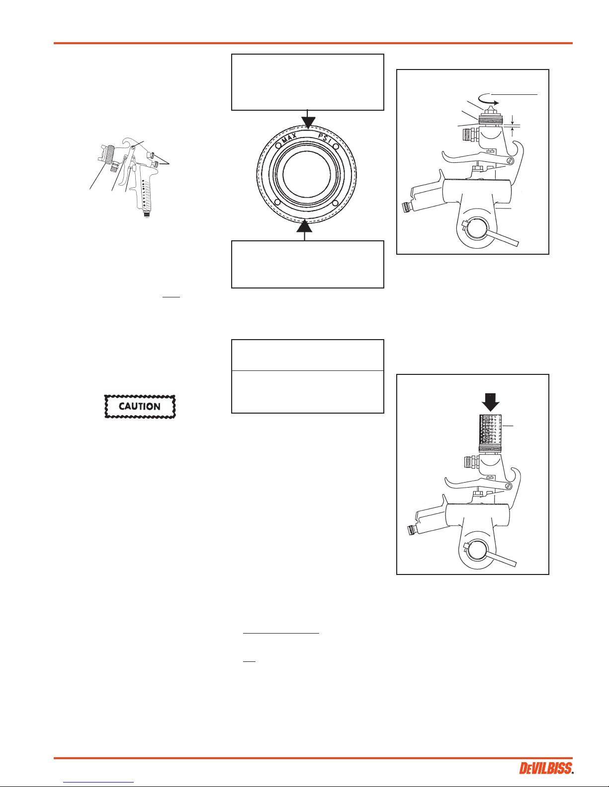
Note
Maximum air pressure required to
assure compliance of 10 psi Max.
Cap Pressure – this reading must
be taken at the spray gun handle
inlet fitting.
30
98
Figure 1 Baffle
Air cap number located on face of
cap – cap number must correspond
with baffle number to assure 10 psi
cap pressure.
Chart 1
Fluid Tip and Needle (Matched Set)
400 Gr. S.S. Tip/303 S.S. Needle
AV-2115-FX Tip (.042")
JGA-402-FX Needle
300 Gr. S.S. Tip with U.H.M.W.
Poly. Insert / 303 S.S. Needle (optional)
AV-4915-FX Tip (.042")
JGA-402-FX Needle
(Standard)
Figure 2
Loosen fluid tip
Fluid Tip
Baffle
Baffle
Gasket
3. Place a 1" socket (12 pt.) over the fluid
tip so that it rests on the top surface of
the baffle. See Figure 3.
4. Press downward on the socket with
sufficient force to free the baffle from
the tip. See Figure 3.
5. The fluid tip and baffle can now be
removed normally from the gun.
Figure 3
3 turns only.
1/16" gap
(approx.)
Bench
Vise
Press Down
To prevent damage to the fluid tip
(3) or fluid needle (32), be sure to
either 1) pull the trigger and hold
while tightening or loosening the
fluid tip or 2) remove fluid needle
adjusting screw (27) to relieve
spring pressure against needle
collar.
FLUID INLET GASKET (6)
REPLACEMENT INSTRUCTIONS
1. Remove fluid inlet adapter (8) with
appropriate wrench.
2. Clean Loctite from gun body inlet
threads and seal area.
3. Place gasket (6) squarely onto the fluid
inlet adapter and push it down until it
is flat against the shoulder.
4. Place a couple of drops of QH-130
(medium strength blue No. 242 Loctite)
on threads before installing fluid inlet
adapter.
5. Torque fluid inlet adapter to 20-25 ft.
lbs. and tighten locknut.
DISASSEMBLY INSTRUCTIONS –
NEW BAFFLE ASSEMBLY
The baffle design incorporates a tight,
press fit with the fluid tip, assuring a
positive air seal. With this design, the
baffle may pull away from the gun body
when the tip is removed and stay locked
onto the fluid tip. If this occurs, follow the
instructions below.
Note
A bench vise should be used for
convenience and to avoid damage
to the spray gun.
1. Secure the spray gun in a bench vise
with padded jaws, or use a rag to avoid
scratching the gun body.
2. Using a 1/2" socket, loosen the fluid tip
three (3) turns only, which will leave
about a 1/16" gap between the baffle
gasket and gun body. See Figure 2. Do
not loosen the fluid tip more than three
(3) turns, as damage may occur.
1" Socket
(12 pt.)
SB-2-187-H (6/2015) 3 / 8
 Loading...