

DeVilbiss JGA-504 Service Bulletin

SERVICE BULLETIN
SB-2-259-B
Replaces SB-2-259-A
Repair Kit KK-5058-2
JGA-504 CONVENTIONAL SPRAY GUN
IMPORTANT: Before using this equipment, read all safety precautions and
instructions. Keep for future use.
DESCRIPTION
The standard JGA-504 spray gun is a general
purpose, heavy duty, high production
spray gun suitable for use with most types
of materials. The fluid passageway is
plated brass and aluminum. The fluid tip
and needle are 300 series stainless steel.
Halogenated hydrocarbon solvents
- for example; 1, 1, 1 - trichloroethane
and methylene chloride - can chemically react with the aluminum in
this gun and cause an explosion
hazard. Read the label or data sheet
for the material you intend to
spray. Do not use spray materials
containing these solvents with this
spray gun.
Important: This gun may be used with
most common coating and finishing
materials. It is designed for use with mildly
corrosive and nonabrasive materials.
If used with other high corrosive or
abrasive materials, it must be expected
that frequent and thorough cleaning will
be required and the necessity for replacement of parts will be increased.
INSTALLATION
1. Attach the air supply line to the air
inlet (26). An air transformer installed
as close as possible to the gun will
provide filtered and regulated air.
Note
When larger diameter air hoses
are used, it is advisable to use an
8' or 10' "whip end" or a smaller
diameter hose at the gun for
greater flexibility or movement.
2. Attach the suction feed cup or fluid
hose to the material inlet.
Note
Protective coating and rust inhibitors
have been used to keep the gun
in good condition prior to shipment.
Before using the gun, flush it with
solvents so that these materials will
be removed from fluid passages.
OPERATION
Mix, prepare and strain the material to be
sprayed according to the paint
manufacturer's instructions.
Strain material through a 60 or 90 mesh
screen.
1. Fill the suction or pressure feed cup
with the material. Do not overfill. Make
sure that the cup lid vent hole is clear,
if using a suction cup.
2. Turn on the gun air at the source of
supply. Adjust the atomization air pressure to 35 psi.
3. Turn on the supply air to the pressure
cup if used.
4. Open the spreader adjustment valve
(10) (Fan) by turning the valve stem
counter-clockwise.
5. Open the fluid needle adjusting screw
(17) by turning counter-clockwise.
6. Spray a test area.
If the finish is too sandy and dry, the
material flow may be too low for the atomization air pressure being used.
If the finish sags, there is too much material
flowing for the atomization air pressure
being used.
Both of the above can be corrected by
increasing or decreasing the atomization
air pressure or the material flow. Pattern
width can be altered by turning the spreader
adjustment valve (10), either clockwise to
decrease the width or counter-clockwise
to increase the width.
See Spray Gun Guide SB-2-001 (latest
revision) for details concerning set up of
spray guns.
PREVENTIVE MAINTENANCE
To clean air cap and fluid tip, brush exterior
with a stiff bristle brush. If necessary
to clean cap holes, use a broom straw
or toothpick. Never use a wire or hard
instrument. This may scratch or burr
holes causing a distorted spray pattern.
To clean fluid passages, remove excess
material at source, then flush with a suitable solvent using a device such as the
SolventSaver™ (see Accessories). Wipe
gun exterior with a solvent dampened
cloth. Never completely immerse in
solvent as this is detrimental to the
lubricants and packings.
Note
When replacing the fluid tip or fluid
needle, replace
time. Using worn parts can cause
fluid leakage. See Charts 1 and 2.
Also, replace the needle packing
at this time. Lightly lubricate the
threads of the fluid tip before
reassembling. Torque to 15-20 ft. lbs.
Do not overtighten the fluid tip.
To prevent damage to the fluid tip
(5) or fluid needle (11), be sure to
either 1) pull the trigger and hold
while tightening or loosening the
fluid tip or 2) remove fluid needle
adjusting screw (17) to relieve
spring pressure against needle
collar.
both at the same
Page 2 SB-2-259-B
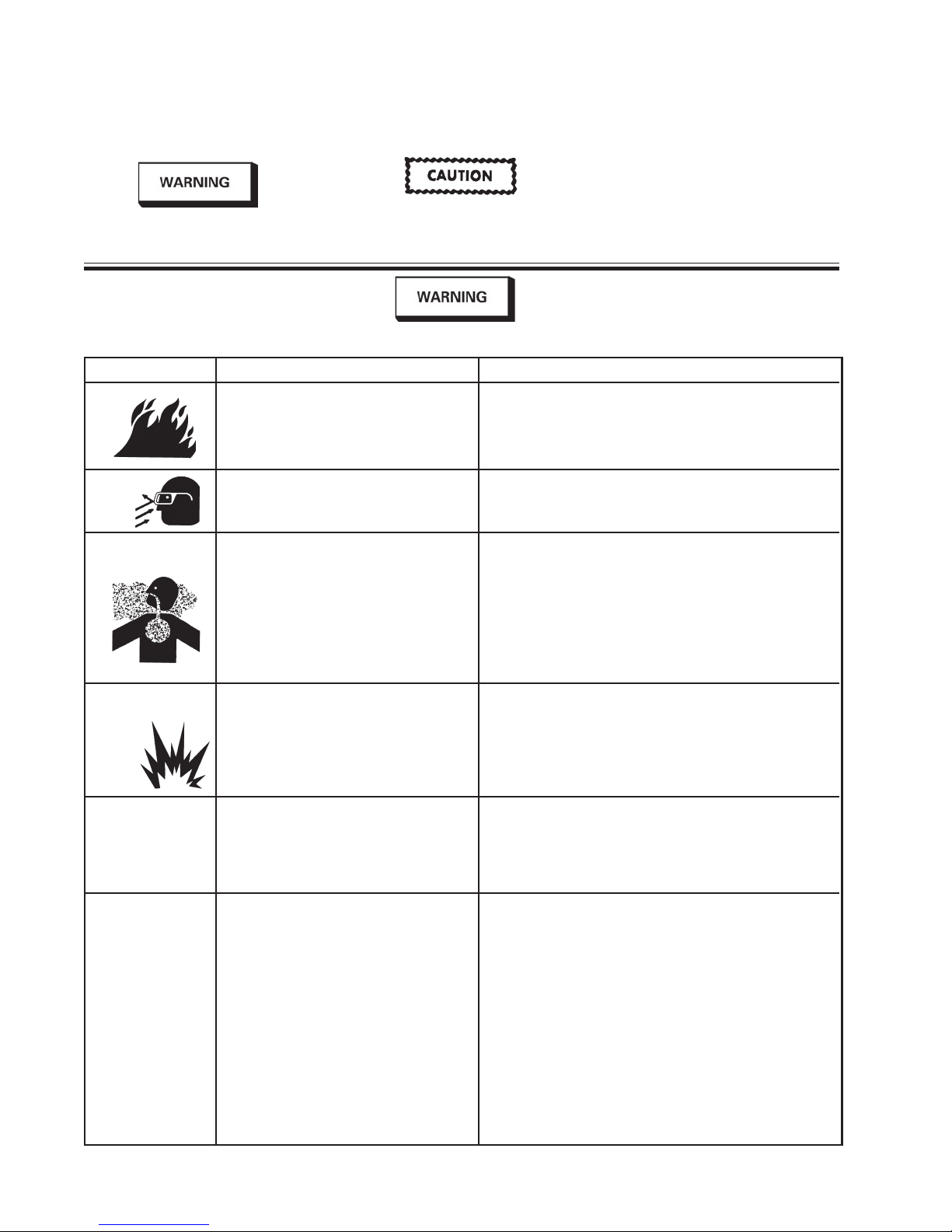
SAFETY PRECAUTIONS
This manual contains information that is improtant for you to know and understand. This information relates to USER SAFETY
and PREVENTING EQUIPMENT PROBLEMS. To help you recognize this information, we use the following symbols.
Please pay particular attention to these sections.
Note
Important safety information - A hazard
that may cause serious injury or loss
of life.
The following hazards may occur during the normal use of this equipment.
Please read the following chart before using this equipment.
HAZARD CAUSE SAFEGUARDS
Fire
Solvent
Spray
Inhaling Toxic
Substances
Explosion Hazard Incompatible
Materials
General Safety
Cumulative Trauma
Disorders (“CTD’s”)
CTD’s, or musculo- CTD's when using hand tools, tend to affect any such symptoms, see a physician immediately. Other early
skeletal disorders, the upper extremities. Factors which may symptoms may include vague discomfort in the hand, loss of
involve damage to increase therisk of developing a CTD include: manual dexterity, and nonspecific pain in the arm. Ignoring early
the hands, wrist, symptoms and continued repetitive use of the arm, wrist and
elbows, shoulders, 1. High frequency of the activity. hand can lead to serious disability. Risk is reduced by avoiding
neck and back. Carpal 2. Excessive force, such as gripping, pinching, or lessening factors 1-7.
tunnel syndrome and or pressing with the hands and fingers.
tendinitis (such as 3. Extreme or awkward finger, wrist, or arm
tennis elbow or positions.
rotator cuff 4. Excessive duration of the activity.
syndrome) are 5. Tool vibration.
examples of CTD’s. 6. Repeated pressure on a body part.
Solvent and coatings can be highly flammable Adequate exhaust must be provided to keep air free of
or combustible especially when sprayed. accumulations of flammable vapors.
During use and while cleaning and flushing, Wear eye protection.
solvents can be forcefully expelled from fluid
and air passages. Some solvents can cause
eye injury.
Certain materials may be harmful if inhaled, or Follow the requirements of the Material Safety Data Sheet
if there is contact with the skin. supplied by your coating material manufacturer.
Halogenated hydrocarbon solvents - for Guns with stainless steel internal passageways may be used
example; methylene chloride and 1, 1, 1 - with these solvents. However, aluminum is widely used in other
Trichloroethane are not chemically compatible spray application equipment - such as material pumps, regulawith the aluminum that might be used in many tors, valves, this gun and cups. Check all equipment items before
system components. The chemical reaction use and make sure they can also be used safely with these
caused by these solvents reacting with solvents. Read the label or data sheet for the material you intend
aluminum can become violent and lead to to spray. If in doubt as to whether or not a coating or cleaning
an equipment explosion. material is compatible, contact your material supplier.
Improper operation or maintenance of Operators should be given adequate training in the safe use and
equipment. maintenance of the equipment (in accordance with the require-
Use of hand tools may cause cumulative Pain, tingling, or numbness in the shoulder, forearm, wrist,
trauma disorders (“CTD’s”). hands or fingers, especially during the night, may be early
7. Working in cold temperatures.
CTD’s can also be caused by such activities
as sewing, golf, tennis bowling, to name a few.
Important information that tells how
to prevent damage to equipment, or
how to avoid a situation that may
cause minor inury.
Smoking must never be allowed in the spray area.
Fire extinguishing equipment must be present in the spray area.
Adequate exhaust must be provided to keep the air free of
accumulations of toxic materials.
Use a mask or respirator whenever there is a chanced of inhaling
sprayed materials. The mask must be compatible with the
material being sprayed and its concentration. Equipment must be
as prescribed by an industrial hygienist or safety expert, and be
NIOSH approved.
ments of NFPA-33, Chapter 15). Users must comply with all local
and national codes of practice and insurance company requirements governing ventilation, fire precautions, operation, maintenance and housekeeping. These are OSHA Sections 1910.94
and 1910.107 and NFPA-33.
symptoms of a CTD. Do not ignore them. Should you experience
Information that you should pay special
attention to.
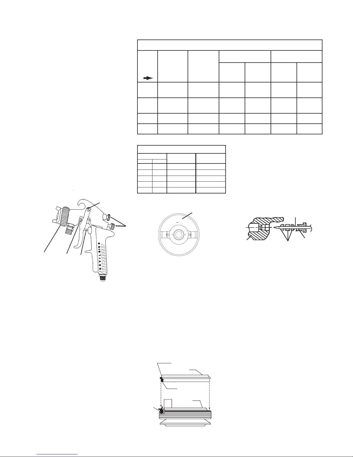
SPRAY GUN LUBRICATION
Daily, apply a drop of SSL-10* spray gun
lube at trigger bearing stud (28) and the
stem of air valve (20) where it enters air
valve assembly. The shank of fluid needle
(11) where it enters packing nut (9) should
also be oiled. Fluid needle packing (8)
should be lubricated periodically. Make
sure baffle (6) and retaining ring (3) threads
are clean and free of foreign matter.
Before assembling retaining ring to baffle,
clean the threads thoroughly, then add
two drops of SSL-10 spray gun lube to
threads. Fluid needle spring (14) and air
valve spring (19) should be coated with
a very light grease, making sure that
any excess grease will not clog the air
passages. For best results, lubricate the
points indicated, daily.
* Not for air tools or high RPM equipment.
A. Trigger Points
B. Packing
C. Adjusting Knobs
D. Baffle Threads
E. Air Valve Cartridge
SB-2-259-B Page 3
Chart 1
Air Caps, Fluid Tips, Fluid Needles and Applications
No. on
Air Cap
Order
No.
80
9000
765
777
Air Cap
With Ring
(Ref. No. 4)
MB-4039-80
AV-440-9000
AV-440-765
AV-440-777
Type of
Fluid
Delivery
SUCTION GTI-413
SUCTION
OR
PRESSURE
PRESSURE GTI-449-12 AV-213-12
PRESSURE GTI-449-12 AV-213-14
Chart 2
Fluid Tips Available
Tip Size
in. mm
0.039 1.0 AV-213-10 Pressure Feed
0.047 1.2 AV-213-12 Pressure Feed
0.055 1.4 AV-213-14 Pressure Feed
0.063 1.6 AV-213-16 Suction Feed
0.070 1.8 AV-213-18 Suction Feed
Fluid Tip
(Ref. No. 5)
Type of Fluid
Delivery
Suction Feed Pressure Feed
Fluid
Needle
(Ref. No. 11)
GTI-413 GTI-449-12
Fluid Tips
Used
(Ref. No. 5)
AV-213-16
OR
AV-213-18
AV-213-16
OR
AV-213-18
Fluid
Needle
(Ref. No. 11)
4. Assemble seal to baffle with angled
side up as shown in diagram. NOTE:
The seal should be a tight fit on the
baffle. If it is a loose fit on the baffle,
assure that it is assembled with the
angled side up.
5. Install baffle on gun.
6. Install fluid tip (5) and tighten to
15-20 ft-lbs.
Fluid Tips
Used
(Ref. No. 5)
AV-213-10
OR
AV-213-12
A
D
B
E
PARTS REPLACEMENT
FLUID INLET GASKET (32)
REPLACEMENT INSTUCTIONS
1. Remove fluid inlet adapter (34) with
appropriate wrench.
2. Clean Loctite from gun body inlet
threads and seal area.
3. Place gasket (32) squarely onto the
fluid inlet adapter and push it down
until it is flat against the shoulder.
4. Use medium strength thread sealant
(i.e. Devcon 2242 blue, or equal) on
threads before installing fluid inlet
adapter.
5. Torque fluid inlet adapter to 20-25 ft.
lbs. and tighten locknut.
PARTS REPLACEMENT
Figure 1 Air Cap
o
N
XX
C
DeVilbiss
GTI-33 Baffle Seal Replacement
1. Remove Fluid Tip (5).
2. Remove Baffle (6).
3. Remove Seal (7) from baffle.
NOTE
The seal is designed to be a tight
fit on the baffle. The seal should
be able to be removed using
your fingers. If you are unable
to remove the seal using your
fingers, insert a small screwdriver between the outer lip and
the back of the baffle and pry
the seal off.
ANGLED SIDE
SEAL
THICK SIDE
Pry here if
necessary
BAFFLE
Air Cap No.
JGA-4035 Packing Replacement
Instructions
Needle
Gun Body
Packing
(3 pieces)
Packing
Nut
1. Remove adjusting knob and needle
spring from gun.
2. Partially withdraw needle from gun
body.
3. Loosen packing nut and remove.
4. Remove old packing.
5. Assemble packing nut to needle.
6. Assemble packing in order shown
to needle.
7. Insert needle all the way into gun
body seating in tip.
8. Install needle spring and adjusting
knob.
9. Thread packing nut into gun body.
10. Tighten packing nut in equal
increments - no more than
1/6 turn at a time.
11. After each adjustment, pull needle
open and observe needle closure.
12. If needle snaps shut, continue
adjusting nut until there is evidence
of needle bind or slow closing.
13. Back off packing nut 1/12 turn to the
point where needle snaps shut.
Packing nut must remain tight
enough to prevent loosening by
hand.
14. Pull needle several times to verify
needle snaps shut and check
packing nut for looseness.
 Loading...