

DeVilbiss HGS-5113, HGS-5122, HGS-5133, HGS-5211, HGS-5212 Service Manual
...
SERVICE MANUAL
EN
HGS STAINLESS STEEL FLUID REGULATORS
IMPORTANT: Read and fol low all
instructions and safety precautions before using this equipment. Retain for future reference.
Air Pilot
Regulator
Tamper Resistant
Regulator
GENERAL
This service bulletin covers installation,
operation, preventive maintenance, parts
replacement, and accessory items for HGS
Fluid Regulators.
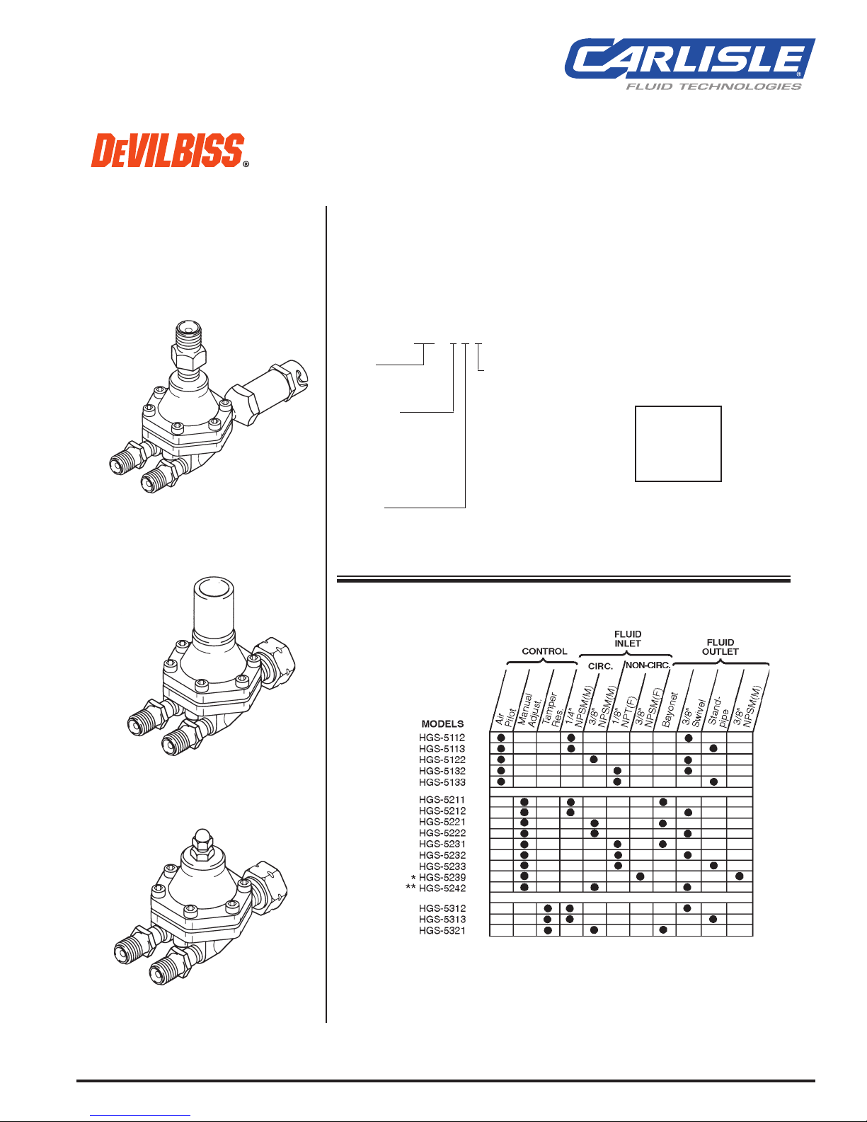
MODEL IDENTIFICATION
HGS-5 X X X
Product
Identification
Control Type
1)Air Pilot
2) Manual Adjustment
3)Tamper Resistant
Adjustment
Fluid Inlet
Configuration
1) 1/4" NPSM(M) Fitting
2) 3/8" NPSM(M) Fitting
3) Non-Circulating 1/8" NPT(F)
Fluid Outlet
Configuration
1) Bayonet Lock
2) 3/8" NPSM(F)
Swivel
3) 1/4" NPSM(M)
Standpipe
9) 3/8" NPSM(M)
MODEL CHART
DESCRIPTION
HGS Fluid Regulators provide regulation
of fluid to the spray gun without stopping
the flow of material which can cause settling of pigmented materials.
NOTE
These regulators may be used
with materials containing chlorinated solvents.
CA PROP
65
PROP 65 WARNING
WARNING: This product contains chemicals
known to the State of California to cause
cancer and birth defects or other
reproductive harm.
Manual
Regulator
SB-6-403-R1 (3/2018) 1 / 8 www.carlisleft.com
* Manual, non-circulating, single gun fluid regulator, primarily used in conjunction
with fluid pumps or dead end systems.
** Manual, non-circulating, can be attached to gun inlet or in line. Note: If used in
color change applications or with catalyzed materials, plug (24) must be removed
and the threads cleaned periodically.

EN
SAFETY PRECAUTIONS
This manual contains information that is important for you to know and understand. This information relates to
USER SAFETY and PREVENTING EQUIPMENT PROBLEMS. To help you recognize this information, we use the following symbols. Please pay particular attention to these sections.
NOTE
Important safety information --
a hazard that may cause serious
injury or loss of life.
MODEL NUMBER TO REGULATOR BODY CROSS REFERENCE CHART
Body Number
Model Number (Less Fittings)
HGS-5112, HGS-5113, HGS-5122 HGS-452
HGS-5132, HGS-5133 HGS-453
HGS-5211, HGS-5212, HGS-5221, HGS-5222 HGS-451
HGS-5231, HGS-5232, HGS-5233, HGS-5239 HGS-455
HGS-5312, HGS-5313, HGS-5321 HGS-450
HGS-5242 HGS-461
1/4" NPSM(M)
STANDPIPE
ASSEMBLY
(HGS-400)
Important information that tells
how to prevent damage to
equipment, or how to avoid a
situation that may cause minor
injury.
3/8" NPSM(F)
NON-
RESTRICTED
FLOW
(HC-4691)
3/8"
SWIVEL
(HC-1000, HGS-1)
BAYONET
ASSEMBLY
(HGS-401-1)
Information that you should pay
special attention to.
ACCESSORY
ITEMS
(STAINLESS STEEL)
OUTLET
CONNECTORS
(STAINLESS STEEL)
15° ANGLE
(ALL MODELS)
TAMPER
RESISTANT
ADJUSTMENT
MANUAL
ADJUSTMENT
1/4"
NPSM(M)
INLET
(HGS-22)
AIR PILOT
CIRCULATING
NPSM(M)
3/8"
INLET
(HGS-21)
1/8" NPT(F)
AIR PILOT
NON-CIRCULATING
INLET
FLUID
REGULATOR
BASIC
ASSEMBLY
(WETTED PARTS
--STAINLESS STEEL
AND PTFE)
DUAL INLET ADAPTERS
CIRCULATING MODELS
ONLY
(STAINLESS STEEL)
SB-6-403-R1 (3/2018)2 / 8www.carlisleft.com
EN
TECHNICAL DATA
PSI (bar)
Fluid Inlet Pressure Min. 50 (3.5)
Max. 300 (20.7)
Regulated Fluid Min. 2 (0.14)
Pressure Range Max. 100 (6.9)
*Typical Flow Rates 150 to 2500 cc's/minute
oz's (grams)
Average Unit Weight
Models - Swivel 7.3 (210)
- Tamper Resist 7.9 (225)
- Standpipe 9.3 (265)
- Bayonet 9.7 (275)
Fluid oz's (ml)
Static Content
Models - Circulating 0.25 (7)
- Non-circulating 0.20 (5)
Wetted Parts 303 and 416 Stainless Steel,
PTFE
Models 17 models offered as standard
* Dependent upon viscocity and specific
gravity of material. Above information
based upon testing with mineral oil with
viscosity of 24 seconds #4 Ford, and
specific gravity of 0.84.
® Registered trademark of Dupont.
INSTALLATION
Risk of hazardous bursting or
equipment damage. Do not exceed 300 PSI (21 bar) maximum
fluid inlet pressure to regulator.
These regulators may be used
with most common coating and
finishing materials. However,
they are not designed for use
with highly abrasive materials.
If used with abrasive materials,
frequent and thorough cleaning
will be required, and replacement of parts will be increased.
1. Where possible, mount the HGS
regulator as shown below with the
fluid outlet facing up. This will prevent trapped air from causing erratic
operation. Trapped air can result
from an "air push" during a color
change cycle, or entrapped air in the
paint.
Fluid outlet should
face upward.
2. Connect fluid inlet supply hose.
Circulating Models
Connect the fluid supply hose to
either fluid inlet adapter (53 or 54).
Connect the return line to the other
adapter (53 or 54).
Non-Circulating Models
Connect the fluid supply hose to
inlet of plug (23 or 40).
3. Connect fluid outlet.
Bayonet Regulators
Attach the bayonet lock body (41) to
the bayonet quick disconnect stem
at the spray gun fluid inlet.
3/8" Swivel Regulators
Thread swivel nut (49) onto fluid inlet
of spray gun body.
Standpipe Regulators
Attach fluid supply hose from spray
gun to bulkhead fitting (52).
4. Connect air inlet.
Air Pilot Regulators
Attach regulated air supply to connector (25).
OPERATION
Risk of hazardous bursting or
equipment damage. Do not exceed 300 PSI (21 bar) maximum
fluid inlet pressure to regulator.
Fluid pressure adjustment range is from
2 psi to 100 psi (0.1 bar to 6.9 bar).
Fluid pressure to regulator inlet is
300 psi (20.7 bar) maximum and 50 psi
(3.5 bar) minimum.
To Regulate Fluid Pressure on Manual
Adjust Models
1. Remove cap nut (1) and loosen lock
nut (2).
2. With a 3/32 inch hex key allen
wrench, adjust hex key allen set
screw (3) for desired pressure setting. Turn set screw (3) clockwise to
increase and counterclockwise to
decrease pressure.
3. Retighten lock nut (2) after desired
pressure setting has been established. Replace and tighten cap nut
(1).
To Regulate Fluid Pressure on Tamper
Resistant Models
1. Using T-handle (4B), loosen lock (6).
2. Engage adjusting screw (5) with torx
key (4A) and turn adjusting screw until
desired pressure setting is reached.
Turn torx key clockwise to increase
pressure and counterclockwise to
decrease pressure.
3. Using the torx key, hold adjusting
screw (5) from turning and tighten
lock (6) with the T-handle (4B).
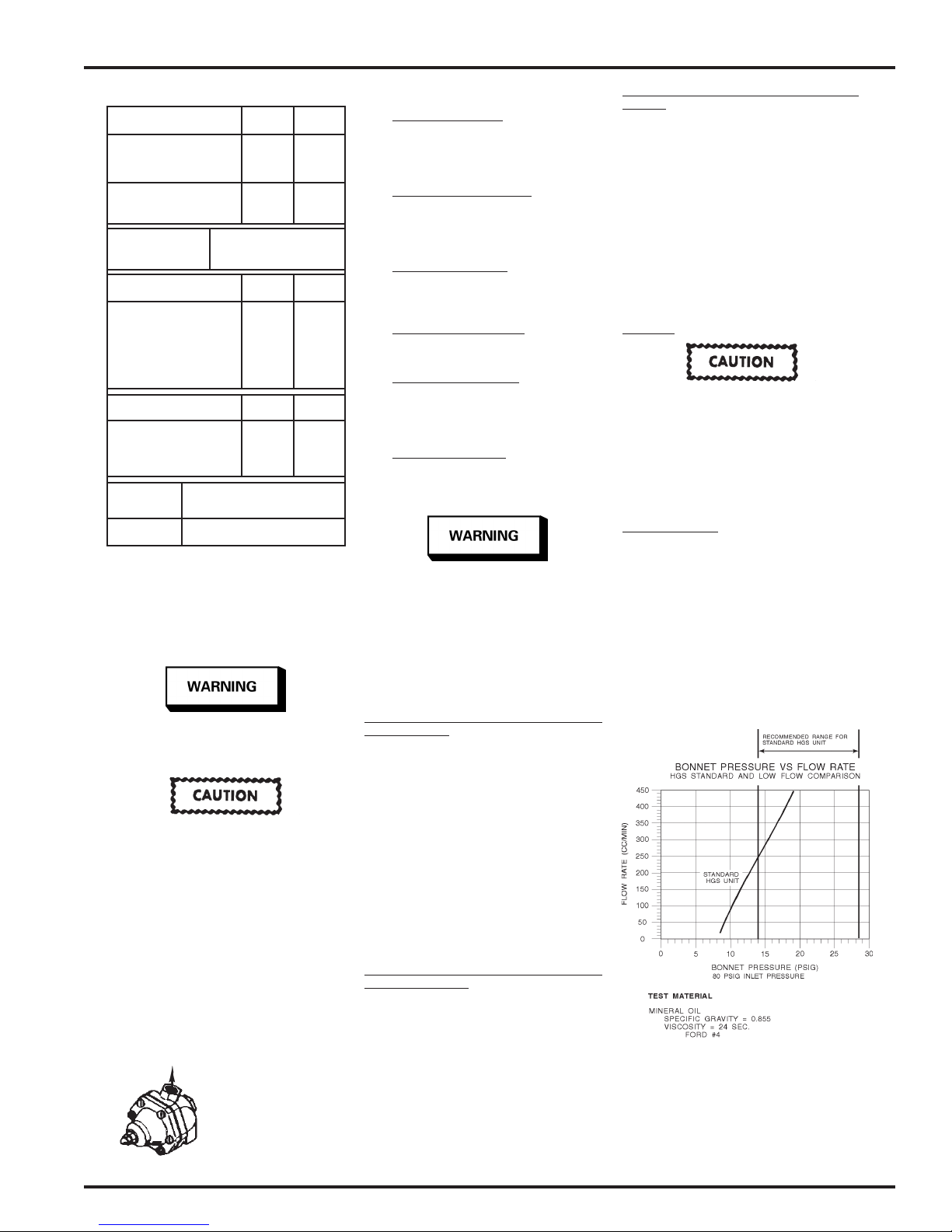
To Regulate Fluid Pressure on Air Pilot
Models
Fluid pressure is controlled by means
of air pressure. To actuate fluid flow, a
minimum of 12-14 psi air pressure must
be applied to the bonnet. Attach one end
of regulated air line to connector (25)
and the other end of the air line to a
remote regulator. Increase air pressure
to increase fluid pressure, and decrease
air pressure to decrease fluid pressure.
Fluid pressure remains constant unless
air pilot regulator setting is altered.
PREVENTIVE MAINTENANCE
Cleaning
Total submersion of the fluid
regulator in solvent for cleaning
purposes will shorten the life
expectancy of the diaphragm.
The frequency with which the fluid
regulator should be cleaned will be the
same as the rest of the system in which
it is being used.
Bayonet Models
When spray gun is removed from service
and fluid regulator is not going to be used
for a period of time, the bayonet end
should immediately be soaked in solvent.
Do not submerge the entire regulator.
This will avoid hardening of material
around the ball and seat which may cause
leakage when regulator is put back in
service. The soaking container should be
an approved closed container if hazardous
solvents are used.
SB-6-403-R1 (3/2018) 3 / 8 www.carlisleft.com
 Loading...