

Page 1
SB-E2-2-362
ISS.02
Operation Manual
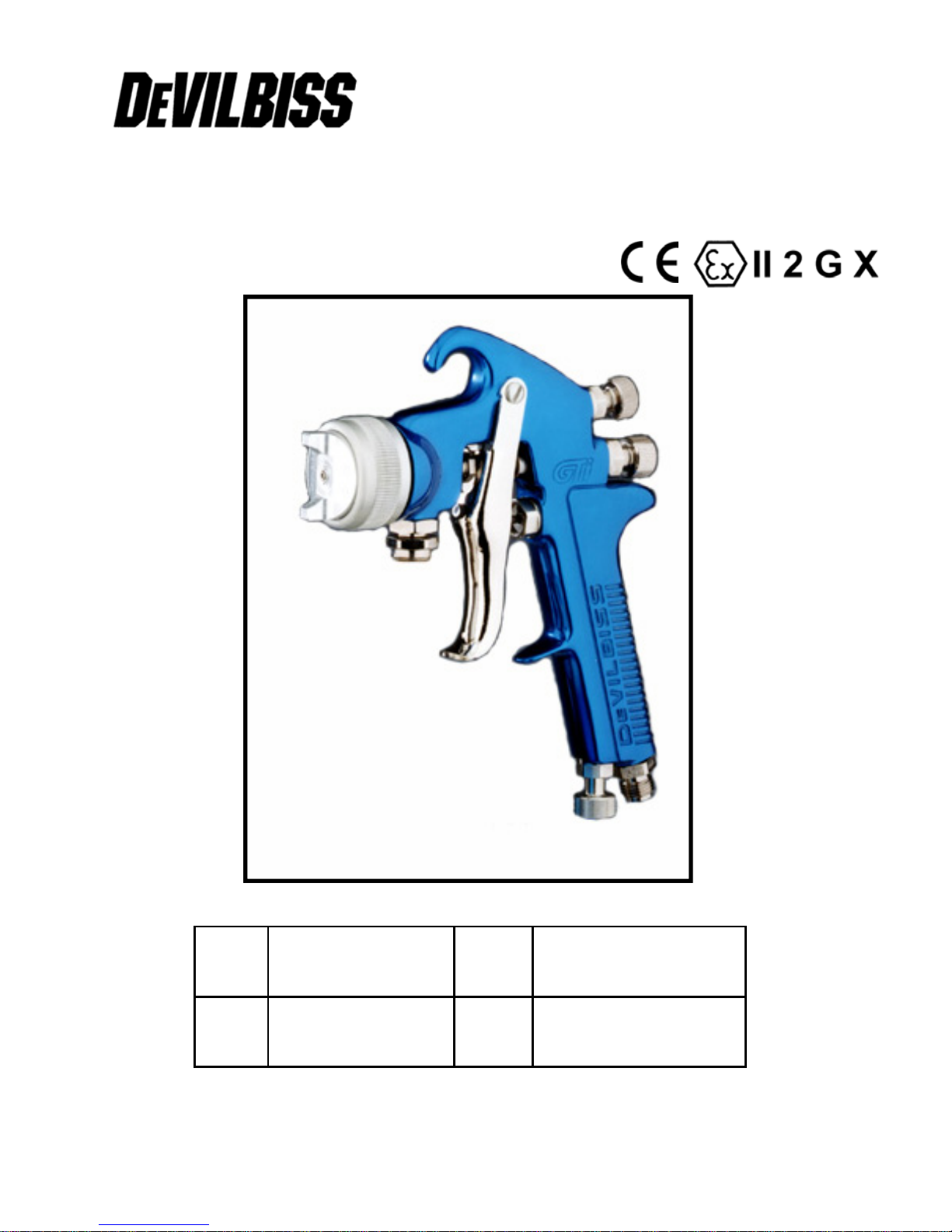
GTi – Pressure Feed Spraygun
E
E
DD
P 8 - 13
P 2 - 7
FF
NL
NL
P 14 - 19
P 20 –25
Page 2
EE
Operation Manual
GTi – Pressure Feed Spraygun
Important
Read and follow all instructions and Safety Prec autions before using this
equipment
Description
The GTi Pressure Feed Spraygun Kit is approved to ATEX regulations 94/9/EC, protection
level;
Important: These Sprayguns are suitable for use with both waterbased and solvent based
coating materials. The design uses EPA compliant atomising (Devilbiss Trans-Tech®)
technology to reduce overspray and improve coating efficiency. Nozzles and Needles are
manufactured in Stainless Steel. These guns are not designed for use with highly corrosive
and/or abrasive m aterials and if used with such materials it must be expected that the need for
cleaning and/or replacement of parts will be increased. If there is any doubt regarding the
suitability of a specific material contact your local Distributor or ITW Finishing direct.
Example:
Ai r cap Number
II 2 G X, Suitable for use in Zones 1 and 2
Model Part Number
GTI-P110B-14
Nozzle size
Gunbody colour
B = bl ue
EC Declaration of Conformi ty
We: I TW Fini s hi ng UK, Ri ngwood Rd, Bour nem out h, Dorset, BH11 9LH, UK, as the
manufacturer of the Spr aygun m odel GTi-P, declare, under our sole responsibility, that the
equipment to which this document relates is in conformity with the following standards or other
normative documents:
BS EN 292-1 PARTS 1 & 2: 1991, BS EN 1953: 1999; and thereby conform to the
protection requirements of Council Directive 89/392/EEC relating to Machinery Safet y
Directive, and;
EN 13463-1:2001, council Directive 94/9/EC relating to Equipment and Protective
Systems i ntended for use in Potentially Explosi ve Atm ospheres protect ion level II 2 G.
This pr oduct also com plies with t he requi r em ents of the EPA guidel i ne s, PG6 / 3 4.
Transfer ef f i ciency certif i cat es are available on request.
B. Ho lt, General Manage r
30th June 2003
ITW Finishing Systems and Products reserve the right to modify equipment specification without prior notice.
© 2003 ITW Finishing Systems and Products
2
Page 3
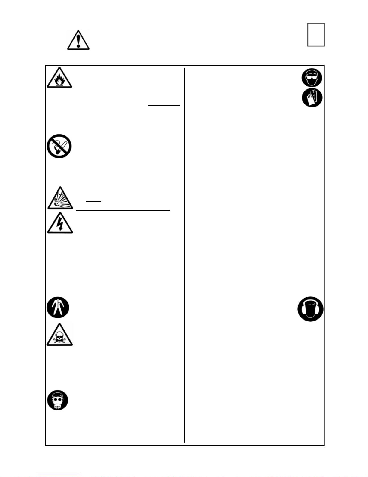
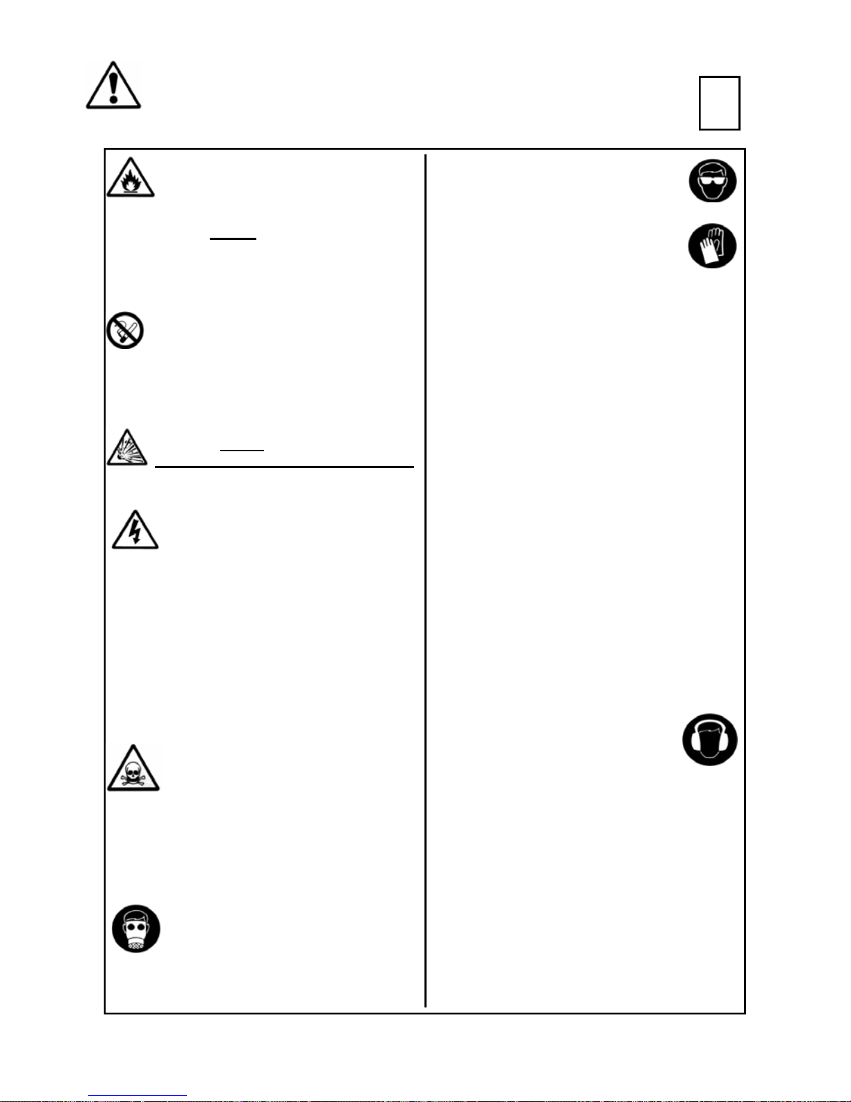
SAFETY WARNINGS
EE
Fire and explosion
Solvents and coating materials
can be highly flammable or
combustible when sprayed. ALWAYS
refer to the coating m ate rial supplie rs
instructions and COSHH sheets
before using this equipment
Users must comply with all local
and national codes of practice
and insurance company
requirements governing
ventilation, fire precautions, operation
and house-keeping of working areas
This equipment, as supplied,
is NOT
Halogenated Hydrocarbons
Static Electricity can be
generated by fluid and/or air
passing through hoses, by the
spraying process and by cleaning nonconductive parts with cloths. To prevent
ignition sources from static discharges,
earth continuity must be maintained to
the spraygun and other metallic
equipment used. It is essential to use
conductive air and/or fluid hoses.
suitable for use with
.
Perso nal P rotective
Equipment
Toxi c vapours – When sprayed,
certain materials may be
poi sonous, create irritation or be
otherwise harmful to health.
Always read all labels and safety data
sheets for the material before spraying
and follow any recommendations. If In
Doubt, Contact Your Material
Supplier
The use of respiratory protective
equipment is recommended at all
times. The type of equipment must be
compatible with the material being
sprayed.
Always wear eye protection when
spraying or cleaning the spraygun
Gloves must be worn when
spraying or cleaning the
equipment
Training – Personnel should be given
adequate training in the safe use of
spraying equipment.
Misuse
Never aim a spraygun at any part of the
body
Never exceed the max. recommended
safe working pressure for the equipment
The fitting of non-recommended or nonoriginal spares may create hazards
Before cleaning or maintenance, all
pressure must be isolated and relieved
from the equipment
The product should be cleaned using a
gun washing machine. However, this
equipment should not be left inside gun
washing machines for prolonged periods
of time.
Noise Levels
The A-weighted sound level of
sprayguns may exceed 85 dB
(A) depending on the set-up
being used. Details of actual noise levels
are available on request. It is
recommended that ear protection is worn
at all times when spraying.
Operating
Spray Equipment using high pressures
may be subject to recoil forces. Under
certain circumstances, such forces could
result in repetitive strain injury to the
operator.
3
© 2003 ITW Finishing Systems and Products
Page 4
EE
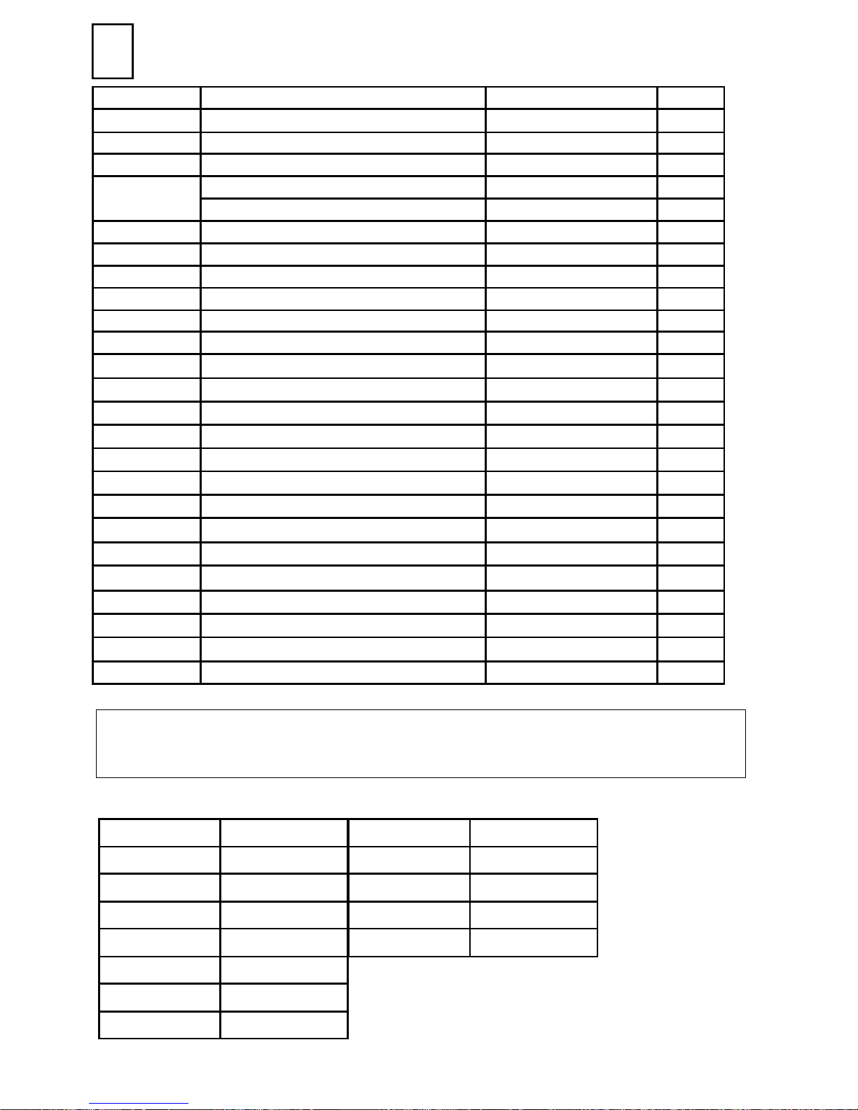
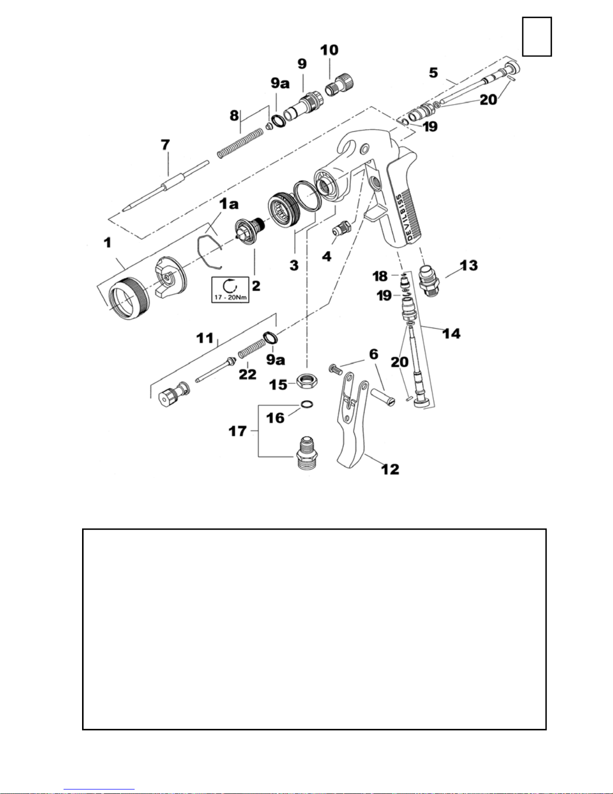
Parts List
Ref. No Description Part Number Qty
*1 Air Cap/Retaining ring GTI-407-* 1
1a Spring Clip JGA-156-K5 1
+2 Nozzle SEE CHART 1
3 Baffle & Seal GTI-425-K 1
Baffle Seal - Kit of 5 GTI-33-K5 1
+4 Packing GTI-439-K2 1
5 Spreader Valve GTI-405-K 1
6 Stud and Screw GTI-408-K5 1
+7 Needle SEE CHART 1
+8 Spring and Pad GTI-409-K5 1
9 Bushing GTI-402-K 1
9a Seal kit of 5 JGS-72-K5 2
10 Needle Adjusting Screw GTI-414-K 1
11 Valve Assembly JGK-449 1
12 Trigger GTI-108 1
13 Connec tor JGA-158 1
14 Airflow Valve GTI-415-K 1
15 Lock Nut JGA-51-K5 1
16 Seal 23165-001 1
17 Fluid Inlet Connector and seal JGA-159-K 1
18 Circlip 25746-007-K5 1
19 Circlip SST-8434-K5 2
20 Seal & Pin Kit ( + SST-8434-K5) GTI-428-K5 2
21 Air valve stem assembly 1
22 Spring JGV-262-K5 1
* - * Denotes Aircap Number - Available Aircaps No’s 110, 122 and 123
+ - Parts included in service Kit (see accessories)
Chart 1
No zzle Needle
GTI-213-085-K GTI-449-10-K
GTI-213-10-K GTI-449-10-K
No zzle Needle
GTI-214-16-K GTI-420-K
GTI-214-18-K GTI-420-K
GTI-213-11-K GTI-449-12-K
GTI-213-12-K GTI-449-12-K
GTI-213-13-K GTI-449-14-K
GTI-213-14-K GTI-449-14-K
GTI-213-15-K GTI-449-14-K
© 2003 ITW Finishing Systems and Products
GTI-214-20-K GTI-420-K
GTI-214-22-K GTI-420-K
4
Page 5
EE
Air supply connection - Universa l 1/4 BSP and NPS
Fluid Supply Connection - Universal 3/8 BSP and NPS
Maximum static Air inlet pressure - P1 = 9 bar (130 psi)
Maximum static Fluid inlet pressure - P2 = 12 bar (200 psi)
Nominal gun Air inlet pressure - 2 bar (29 psi)
with gun triggered
Gun Weight - 640 g
Gun body - Anodised Aluminium
Nozzle - Stainless steel
Needle - Stainless Steel
Specification
Materials of Construction
5
© 2003 ITW Finishing Systems and Products
Page 6

EE
Installation
Important: To ensure that this
equipment reaches you in first class
condition, protective coatings have
been used. Flush the equipment
through with a suitable solvent
before use.
1. Attach air hose to connector (13).
Operation
1. Mix coating material to
manufacturers instructions
2. Turn needle adjusting screw (10)
clockwise to prevent movement.
3. Turn pattern valve (5) counterclockwise to fully open
4. Adjust inlet air pressure to give 2
bar (29psi) at the gun inlet with
the gun triggered. (pressure
gauge attachment shown under
Accessories is recommended for
this).
5. Turn needle adjusting screw
counter clockwise until first thread
shows.
6. Test spray. If the finish is too dry
reduce airflow by reducing inlet
pressure. If finish is too wet
reduce fluid flow by turning needle
screw (10) clockwise or reducing
the fluid pressure. If atomisation is
too coarse, increase inlet air
Recommended hose size 8 mm
bore.
2. Attach fluid supply hose to Fluid
Inlet (17).
3. Air supply should be filtered and
regulated.
pressure. If too fine reduce inlet
pressure.
7. The pattern size can be reduced
by turning adjusting valve (5)
clockwise.
8. Hold gun perpendicular to surface
being sprayed. Arcing or tilting
may result in uneven coating.
9. The recommended spray distance
is 150-200 mm (6”-8”).
10. Spray edges first. Overlap each
stroke a minimum of 50%. Move
gun at a constant speed.
11. Always turn off air and fluid supply
and relieve pressure when gun is
not in use.
Air Flow Valve (14)
1. If the airflow valve (14) is fitted
this can be used to reduce the
inlet pressure through the gun.
Screw the Adjusting Knob in to
reduce pressure.
Preventative Maintenance
1. Turn off air and coating supply
and relieve pressure in the
supply lines, or if using QD
system, disconnect from airline
and fluid line.
2. Remove air cap (1) and clean. If
any of the holes in the cap are
blocked with coating material use
© 2003 ITW Finishing Systems and Products
a toothpick to clean. Never use
metal wire which could damage
the cap and produce distorted
spray patterns
3 Ensure the tip of the nozzle (2) is
clean and free from damage.
Build up of dried paint can distort
the spray pattern.
6
Page 7

1. Lubrication – stud/screw (6),
needle (7) and air valve (11)
should be oiled each day.
EE
Replaceme nt of Parts
Nozzle (2) and Needle (7) –
Remove parts in the following order:
10, 8, 7, 1 and 2. Replace any worn
or damaged parts and re-assemble
in reverse order. Recommended
tightening torque for nozzle (2) 1720 Nm (150-180 lbf in)
Packing – Remove parts 10, 8, 7.
Unscrew cartridge (4). Fit new
cartridge finger tight. Re-assemble
parts 7, 8, and 10 and tighten
cartridge (4) with spanner sufficient
to seal but to allow free movement
of needle. Lubricate with gun oil.
Air valve (11) – Remove Trigger,
parts 6 and 12. Unscrew valve
assembly. Re-assemble, fitting
spring to valve head before fitting
valve.
Spreader valve (5) – Caution:
always ensure that the valve is in
the fully open position by turning
screw fully counter-clockwise before
fitting to body.
Air cap / Nozzle Sel ect ion
Refer to coating material
manufacturers recommendations or
Accessories
Spanner – order SPN-5
Cleaning Brus h – order 4900-5-1-K3
Service Kit – For sizes 16 to 22 order GTI-416 and nozzle size as required
(i.e GTI-416-18)
For sizes 085 to 15 order GTI-426 and nozzle as required size as required
(i.e GTI-426-14)
Pressure gauge Attach ment – order GA-515
Gun M ount ed Regulator – order DVR-501
Lubricant - order GL-1-K10
7
© 2003 ITW Finishing Systems and Products
Page 8
DD
Betriebsan leitung
GTi – Kessel-Spritzpistole
Wichtig
Bitte lesen und befolgen Sie alle Anweisungen und Sicherheitshinweise,
bevor Sie das Ger ät in Betrieb nehmen
Beschreibung
Diese Spritzpistole kann sowohl mit wasserlöslichen als auch mit auf Lösungsmitteln basierenden
Beschichtungsstoffen verwendet werden. Bei der Bauart wird eine EPA-gemäße Zerstäubungstechnologie (Devilbiss Trans-Tech®) eingesetzt, um den Farbnebel zu verringern und den Auftragswirkungsgrad zu verbessern. Düsen und Nadeln sind aus rostfreiem Stahl.
Die GTi Kessel-Spritzpistole ist gemäß Richtlinie ATEX 94/9/EG, Schutzstufe II 2 G X, zugelassen
und kann in den Zonen 1 und 2 eingesetzt werden.
Wichtig: Diese Spritzpistolen si nd nicht für den Einsatz mit stark korrosiven und/oder abreibenden
Materialien geeignet. Bei Ei nsatz m it solchen Stoffen muss davon ausgegangen we rden, dass der
Aufwand für die Reinigung und/oder der Bedarf an Ersatzteilen steigt. Sollte es irgendwelche
Z weifel geben, ob ein bestim mtes Material geeignet ist, wenden S ie sich bitte an Ihren ör tl ichen
Händler oder direkt an ITW Oberflächentec hnik.
Modell-Teilenummer
Beispiel: GTI - P122- 14B
Luftkappe Größe der Düse
(14 = 1,4 mm)
EG-Konformitätserklärung
Wir: ITW Finishing UK, Ringwood Rd, Bournemouth, Dorset, BH11 9LH, UK erklären
eigenverantwortlich als Hersteller des Spritzpistolenmodells GTi-P, dass das Gerät, auf das sich
dieses Dokument bezieht, die folgenden Richtlinien oder Normendokumente einhält:
BS EN 292-1 TEILE 1 & 2: 1991, BS EN 1953 :1999.
Daher halten diese Geräte die Schutzanforderungen der folgenden Vorschriften ein: Richtlinie
des EU-Rates 89/392/EWG zur Masc hine nric ht linie und EN 13463-1:2001, Richtlinie des EU-
Rates 94/9/EG zu Geräte und Schutzsysteme, die für den Einsatz in potenziell explosiven
Umgebungen eingesetzt werden, Schutzstufe II 2 G X.
Dieses Spritzpistole hält auch die EPA-Richtlinien PG6/34 ein. Übertragungseffizienzdokumente
werden auf Anfrage bereitgestellt.
B. Holt, General Manager
30th June 2003
ITW Finishing Systems and Products behält sich das Recht vor, die technischen Daten der Geräte
ohne vorherige Benachrichtigung zu ändern.
© 2003 ITW Finishing Systems and Products
8
Page 9
SICHERHEITSHINW EISE
DD
Feuer und Explosionen
Lösem ittel und Beschichtungs stoffe
können leicht entflammbar oder brennbar
sein, wenn sie verspritzt oder versprüht werden.
Schlagen Sie IMMER
Herstellers für den Beschichtungsstoff und
die COSHH-Blätter nach, bevor Sie diese
Geräte b enutzen.
Die Anwender müssen sämtliche örtlichen
und nationalen Arbeitsvorschriften und
Anforderungen der Behörden und Ber ufsgenossenschaften erfüllen, und zwar hinsichtlich
Belüftung, Brandbekämpfung, B etrieb und
allgemeine Praxis am Arbeitsplatz.
Die se Geräte sind in ihre m ge liefe rten
Zustand NICHT
halogenisiertem Kohlenwasserstoff
verwendet zu werden.
Beim Durchfluss von Flüssigkeiten und/
oder Luft durch Schläuche, beim Spritzlackier en und beim Reinigen von nicht-
leitenden Teilen mit Lappen können
statische Aufladungen entstehen. Die
Spritzpistole und alle eingesetzten Geräte aus
Metall müssen ständig geerdet sein, um
Zündquellen von statischen Entladungen zu
vermeiden. Es müssen auf jeden Fall leitende
Luft- und/oder Materialschläuche verwendet
werden.
die Anweisungen des
dazu geeignet, mit
Schutzausr üst ung f ür das
Personal
Giftige Dämpfe – Bestimmte Materialien
sind giftig, können Ausschläge verursachen oder auf andere Weise gesund-
heitlich schädigend sein. Lesen Sie bitte
immer alle Schilder und Datenblätter f ür das
Material durch, bevor Sie mit dem Lackieren
beginnen; befolgen Sie alle Empfehlungen. Falls
Zweifel bestehen, wenden Sie sich bitte an
Ihren Materiallieferanten.
Es wird empfohlen, jederzeit Atem-
schutzgeräte zu verwenden. Die
Schutzstufe der Geräte muss dem
jeweils verarbeiteten Material ent
sprechen.
Augenschutz muss immer beim
Lackieren oder bei der Reinigung
getragen werden.
Handschuhe müssen immer beim
Lackieren oder bei der Reinigung
getragen werden.
Training – Das Personal muss für den gefahrlosen E insatz der Spritzgeräte entsprechend
ausgebildet werden.
Missbrauch
Eine Spritzpistole darf auf keinen Fall auf
irgendeinen Körperteil gerichtet werden.
Der maximale, empfohlene, sichere Arbeitsdruck
für die Geräte darf niemals überschritten werden.
Der Einbau von Ersatzteilen, die nicht empfohlen
werden oder nicht original sind, könnte ein
Gefahrenrisiko darstellen.
Vor der Reinigung oder einer Wartung muss die
Druckluftversorgung abgetrennt werden; der
Restdruck muss in den Geräten abgebaut
werden.
Spritzgeräte sollten mit einer Wascheinrichtung
für Spritzgeräte ger einigt werden. Die Geräte
sollten jedoch nicht über lange Zeitr äume in der
Wascheinrichtung belassen werden.
Geräuschpegel
Der A-gewichtete Geräuschpegel von
Spritzpistolen kann 85 dB (A) überschreiten, abhängig von der verw endeten Luftkappe. Einzelheiten über die
tatsächlichen Geräuschpegel sind auf
Anfrage erhältlich. Es wird empfohlen, beim
Spritzlackieren immer einen Gehörschutz zu
tragen.
Betrieb
Spritzgeräte, die mit hohem Druck arbeiten,
können Rückstöße erzeugen. In bestimmten
Situationen können diese Rückstöße Überlastungsschäden beim Bediener verursachen.
9
© 2003 ITW Finishing Systems and Products
Page 10

DD
Ref. Nr. Beschreibung Teilenummer Stück
1* Luftkappe mit Haltering GTI-407-.. 1
1a Feder (5 Stück) JGA-156-K5 1
Stückliste
2*
3 Luftverteilerring GTI-425-K 1
3a Dichtung Luftverteilerring (5 Stück) GTI-33-K5 1
4 Farbnadelpackung (2 Stück) GTI-439-K2 1
5 Strahlregulierventil GTI-405-K 1
6 Bolzen mit Schraube (je 5 Stück) GTI-408-K5 1
7
8 Feder mit Plättchen (5 Stück) GTI-409-K5 1
9 Farbnadelzylinder GTI-402-K 1
9a Dichtung (10 Stück) JGS-72-K10 2
10 Farbnadelstellschraube GTI-414-K 1
11 Luftventil JGK-449 1
Düse (bis 1,5 mm) GTI-213-...-K 1
Düse (1,6 mm bis 2,2 mm) GTI-214-...-K 1
Farbnadel 0,85/1,0 mm GTI-449-10-K 1
Farbnadel 1,1/1,2 mm GTI-449-12-K 1
Farbnadel 1,3/1,4/1,5 mm GTI-449-14-K 1
Farbnadel 1,6 – 2,2 mm GTI-420-K 1
12 Fingerabzug GTI-108 1
13 Lufteingangsnippel JGA-158 1
14 Luftfeinregulierventil GTI-415-K 1
15 Sicherungsmutter (5 Stück) JGA-51-K5 1
16 Dichtung (10 S t ück ) 23165-001-K10 1
17 Farbeinlassnippel JGA-159-K 1
18 Sprengring (5 Stück) 25746-007-K5 1
19 Sprengring (5 Stück) SST-8434-K5 2
20 Dichtung + Stift (5 Stück)
21 Luftventilkegel JGS-431-1 1
22 Feder (5 Stück) JGV-262-K5 1
* verfügbare Luftkappen: Nr. 122 und 123
** verfügbare Düsengrößen:
GTI-213-... 0.85, 1.0, 1.1, 1.2, 1.3, 1.4, 1.5 mm
GTI-214-... 1.6, 1.8, 2.0, 2.2 mm
inkl. SST-8434-K5
GTI-428-K5 2
© 2003 ITW Finishing Systems and Products
10
Page 11

DD
Lufteingang - Universal 1/4“ BSP und NPS
Materialeingang- Universal 3/8“ BSP und NPS
Maximaler, statischer Einlassdruck - P1 = 9 bar (130 psi)
Maximaler, statisc her Materialdruck - P2 = 12 bar (200 psi)
Nominaler Pistolendruck bei
abgezogener Pistole - 2 bar (29 psi)
Pistolengewicht - 640 g
Maximale Einsatztemperatur - 40º C
Techni sc he Daten
11
© 2003 ITW Finishing Systems and Products
Page 12

DD
Inbetriebnahme
Wichtig: Um zu gew ährleisten, dass Sie die
Geräte in erstklassigem Zustand erhalten,
wurden sie mit einer Schutzschicht überzogen. Spülen Sie die Geräte vor dem
Gebrauch mit einem geeigneten
Lösemittel durch.
1. Schließen Sie den Luftschlauch an den Lufteingang (13) an. Ein Schlauch mit einem
Inne nd urchmesser von mindeste ns 8 mm
Betrieb
1. Die Beschichtungsstoffe laut Hersteller-
angaben mischen.
2. Die Farbnadelstellschraube (10) gegen
den Uhrzeigersinn drehen, bis der erste
Gewindegang sichtbar wird.
3. Drehen Sie das Strahlregulierventil (5)
gegen den Uhrzeigersinn ganz auf.
4. Stellen Sie den Einlassluftdruck so ein,
dass sich am Pistoleneinlass bei
abgezogener Pistole ein Druck von 2 bar
ergibt. Dazu wird der Einsatz des LuftRegulierventils mit Manometer empfohlen
(HAV-501-B).
5. Spritztes t. Wenn der Auftrag zu nass ist,
kann die Materialzufuhr reduziert werden,
indem die Farbnadelstellschraube (10) im
Uhrzeigersinn gedreht wird oder der
Materialdruck verringert wird. Wenn die
Zerstäubung zu grob erfolgt, kann der
Einlassluftdruck erhö ht werde n. Wenn si e
zu fein erfolgt, kann der Einlassluftdruck
gesenkt werden.
6. Der Spritzstrahl kann reduziert werden,
wird empfohlen. Der Schlauch muss elektrisch leitend sein. Prüfen Sie die elektrische
Leitfähigkeit von der Spritzpistole zur Erde
mit einem Ohmmeter. Der Widerstand sollte
unter 106 Ω liegen.
2. Den Schlauch für die Materialversorgung
am Materialeingang (17) anbringen.
3. Die Luftzufuhr sollte gefiltert und reguliert
sein.
indem das Strahlregulierventil (5) im Uhrzeigersinn gedreht wird.
7. Pistole senkrecht zur zu spritzenden
Fläche führen. Ein Kippen oder Neigen
kann zu ungleichmäßigen Beschichtungsstärken führen.
8. Der empfohlene Spritzabstand beträgt
150 - 200 mm.
9. Die Ränder zuerst spritzen. Jede Bahn
um mindestens 50 % überlappen. Die
Pistole mit gleichförmiger Geschwindigkeit bewegen.
10.Wenn die Pistole nicht verwendet wird,
soll die Luftversorgung immer abgedreht
und der Druck abgelassen werden.
Luftfeinregulierventil (14)
1. Das Luftfeinregulierventil (14) wird dazu
verwendet, den Druck am Einlass zur
Pistole zu reduzieren. Die Stellschraube
hineinschrauben, um den Druck zu reduziere n.
1. Die Luft- und Materialversorgung abdrehen
und den Druck aus den Versorgungsleitungen ablassen; wenn ein Schnellwechselsystem verwendet wird, von der Luft- und
Materialversorgung abhängen.
2. Nehmen Sie die Luftkappe (1) ab und
reinigen Sie sie. Wenn die Löcher in der
© 2003 ITW Finishing Systems and Products
V orbeugende Wa rtung
Luftkappe mit Beschichtungsmaterial verschmutzt sind, können diese mit einem
Zahnstocher gereinigt werden. Metalldraht darf dazu jedoch niemals verwendet
werden, da die Luftkappe dadurch
beschädigt werden könnte, wodurch ein
ungleichmäßiger Spritzstrahl entsteht.
12
Page 13

DD
3. Sorgen Sie dafür, dass die Spitze der Düse
(2) sauber und nicht beschädigt ist. Ablagerungen aus getrocknetem Lack können
den Spritzstrahl ebenfalls verfälschen.
Austa usch von Teilen
Düse (2) und Farbnadel (7) – Teile in der
folgenden Reihenfolge ausbauen: 10, 8, 7, 1
und 2. Alle abgenützten und beschädigten
Teile ersetzten und in umgekehrter
Reihenfolge zusammenbauen. Empfohlenes
Drehmoment für die Düse (2) 17 - 20 Nm.
Farbnadelpackung (4) – Teile 10, 8 und 7
ausbauen. Farbnadelpackung (4) abschrauben. Neue Farbnade lpackung handfest einschrauben. Teile 7, 8 und 10 einbauen und
Farbnadelpackung (4) mit dem Pistolenschlüssel ausreichend festziehen, damit sie
dicht sitzt; die Farbnadel muss sich jedoch
frei bewegen lassen.
Luftventil (11) – Fingerabzug entfernen.
Luftventil herausschrauben. Zusammen-
bauen und Feder in den Ventilkopf ein-
4. Schmierung : Bolzen/Schraube (6), Farb-
nadel (7) und Luftventil (11) sollten jeden
Tag eingeölt werden.
setzen, bevor das Ventil wieder eingebaut
wird.
Strah lreg u lierve n ti l (5) – V o rsich t: Sorgen
Sie dafür, dass das Ventil immer voll
geöffnet ist, bevor es im Pistolenkörper
montiert wird; dazu drehen Sie die Schraube
ganz gegen den Uhrzeigersinn.
Luftkappen- und Düsenauswahl
Schlagen Sie die Empfehlungen vom
Hersteller für den Beschichtungsstoff nach
oder schauen Sie auf den Internetseiten von
ITW Oberflächentechnik nach:
www.itw-finishing.de
Zubehör
Pistol enschl üssel – Bestell-Nr. SPN-5
Reini gungsbür s t e ( 3 St ück) – Bestell-Nr. 4900-5-1-K3
Düsensatz – Bestell-Nr. GTi-451-...-... (für 0,85/1,0/1,1/1,2/1,3/1,4/1,5 mm)
mit Düse, Farbnadel, Luftkappe und Haltering (bitte Düsengröβe und Luftkappe angeben)
Düsensatz – Bestell-Nr. GTi-450-...-... (für 1,6/1,8/2,0/2,2 mm)
mit Düse, Farbnadel, Luftkappe und Haltering (bitte Düsengröβe und Luftkappe angeben)
Fil ter für Luftei ngang – Bestell Nr. HAF-507
Luftregul i er vent il mit Manomet er – Bestell-Nr. HAV-501-B
Mess - und Mi schbecher ( 50 St ück) – Bestell Nr. MC-1-K50
Viskosit ät s- M essbecher DIN4 ( 2 Stück) - Bestell-Nr. 7000-114-K2
Wart ungsöl , silikonf r ei (Fl asche mit 75 ml) – Bestell-Nr. 6-428
Schmi er f e t t , sil i konfrei (Tube mit 5 0 g) – Bestell-Nr. AGMD-010
Handrei ni gungs t ücher SCR UBS (6 Eimer à 72 Tücher ) - Bestell-Nr. 192218-K6
13
© 2003 ITW Finishing Systems and Products
Page 14

FF
Manuel d'utilisation
GTi – Pistolet de pulvérisation sous pression
Important
Lir e attentivement toutes l es instructions et sui vr e les Consi gnes de séc urité
avant d'utiliser ce matériel
Description
Le Kit pistolet sous pression GTi est conforme à la réglementation ATEX 94/9/CE ; niveau de
protection 11 2 G X, et peut être utilisé dans les Zones 1 et 2
Im por t ant : Ces pistolets peuvent être utilisés avec des produits à base aqueuse et à base de
solvant. La conception fait appel à une technologie de pulvérisation 'Devilbiss Trans-Tech®',
conforme aux règles EPA, qui réduit les effets de brouillard et améliore le rendement en
application. Les buses et les aiguilles sont en acier inoxydable. Ces pistolets ne sont pas conçus
pour l’utilisation avec des produits fortement corrosifs et/ou abrasifs. S’ils sont utilisés avec de
tels produits, ils devront être nettoyés et/ou les pièces devront être remplacées plus souvent. Si
vous avez le moindre doute en ce qui concerne le caractère approprié d’un produit spécifique,
contactez votre distributeur local ou ITW Finishing directement.
Numéro de référence du modèle
Exemple :
Chapeau d'air Dimension de la buse
(14 = 1,4 mm)
Finition du corps du pistolet
B= Anodisé bleu
Déclaration de conformité CE
Nous : ITW Finishing UK, Ringwood Rd, Bournemouth, Dorset, BH11 9LH, Royaume-Uni, en tant
que fabricant du Pistolet GTi–P, déclarons, sous notre entière responsibilité, que le matériel auquel
ce document se rapporte est conforme aux normes suivantes ou à d'autres documents normatifs :
BS EN 292-1 PARTI ES 1& 2: 1991, BS EN 1953:1999 ; et est donc conforme aux exigences de
protection de la Directive du conseil 89/392/CEE relative à la Directive sur la sécurité des
machines et de
EN 13463-1:2001, la Directive du conseil 94/9/CE relative aux Équipements et systèmes de
prot ect ion prévus pour l e s atmos phèr es potenti ellement explosives , niveau de protection 11 2
G X.
Ce produit est aussi conforme aux exigences des dir ectives de l 'EPA, PG6/ 34. Des certif i cats
de rendem ent de tra nsf er t sont disponibl es sur demande.
30th June 2003
GTI - P 110B- 14
B. Holt, Directeur général
ITW Finishi ng Sys t em s and Product s se réserve le droit de modifier les spécifications des
équipements sans préavis.
© 2003 ITW Finishing Systems and Products
14
Page 15

CONSIG NES DE S E CURITE
FF
Incendie et explosion
Les solvants et produits de
revêtement peuvent être extrêmement
inflammables ou combustibles lorsqu'ils sont
pulvérisés. Se reporter TOUJOURS aux
instructions des fournisseurs de produits
et aux fiches COSHH avant d'utiliser le
pistolet.
Les utilisateurs doivent se conformer
aux codes de pratique locaux et
nationaux et aux exigences des
compagnies d'assurance régissant la
ventilation, les précautions à prendre contre
l'incendie, le fonctionnement et la surveillance
des lieux de travail.
Ce pistolet, tel qu'il est fourni, n'est PAS
prévu pour les hydrocarbures halogénés.
De l'électricité statique peut être
produite par le liquide et/ou l'air qui
circule dans les flexibles. Pour éviter
cela, le matériel de pulvérisation et
l'objet pulvérisé doivent toujours être mis à la
masse.
Équipement de protection individuel
Vapeurs toxiques – Lorsqu'ils sont pulvérisés,
certains produits peuvent être toxiques,
irritants ou généralement nocifs. Toujours lire
les étiquettes et les fiches signalétiques des
produits avant de les pulvériser, et respecter
les consignes de sécurité. En cas de
doute, contacter le fournisseur du
produit.
Formation – Le personnel doit être formé à
l'utilisation sans risque apprendre du pistolet.
Mauvaise ut i lisat ion
Ne jamais diriger le pistolet vers une
quelconque partie du corps.
Ne jamais excéder la pression de
service maximale recommandée
pour le pistolet.
La pose de pièces détachées nonrecommandées ou qui ne sont pas d'origine
peut être à l'origine de risques.
Avant le nettoyage ou l'entretien, isoler et
évacuer la pression du pistolet.
Nettoyer le pistolet avec une machine
spécialement conç ue à cet effet. To ute fois, ne
pas laisser le pistolet à l'intérieur de la
machine pendant une période prolongée.
Niveaux sonores
Le niveau sonore pondéré A des pistolets de
pulvérisation peu dépasser 85 dB (A) selon la
configuration utilisée. Le détail des niveaux
sonores actuels est disponible sur demande.
Le port de protecteurs d'oreilles est
recommandé à tout moment pendant la
pulvérisation.
Il est recommandé d'utiliser un appareil de
protection respiratoire à tout moment. Le type
d'appareil doit être compatible avec le produit
pulvérisé.
Toujours porter une protection oculaire pour
pulvériser ou nettoyer le pistolet.
Porter des gants pour pulvériser ou
nettoyer le pistolet.
15
© 2003 ITW Finishing Systems and Products
Page 16

FF
Repère Description Réf Qté
*1 Chapeau d'air/bague de retenue GTI-407-* 1
1a Clip à ressort JGA-156-K5 1
+*2 Buse Voir tableau 1
Liste de pièces
3
+4 Presse-étoupe GTI-439-K2 1
5 Valve de réglage de jet GTI-405-K 1
6 Axe et vis de gâchette GTI-408-K5 1
+7 Aiguille (pour buse GTI-214) Voir tableau 1
+8 Ressort et pastille d'appui GTI-409-K5 1
9 Douille d'aiguille GTI-402-K 1
9a Joint - Kit de 5 JGS-72-K5 2
10 Vis de réglage d'aiguille GTI-414-K 1
11 Ensemble valve JGK-449 1
12 Gâchette GTI-108 1
13 Raccord d'air 1/4 universel JGA-158 1
14 Vanne d'écoulement d'air GTI-415-K 1
15 Contre-écrou JGA-51-K5 1
16 Joint 231645-001 1
17 Connecteur et joint d'entrée de liquide JGA-159-K 1
Bague déflectrice et joint GTI-425-K 1
Kit de 5 joints de bague déflectrice GTI-33-K5 1
18 Circlip - Jeu de 5 25746-007-K5 1
19 Circlip - Jeu de 5 SST-8434-K5 2
20 Kit joint + broche ( + SST-8434-K5) GTI-428-K5 2
21 Vanne 1
22 Ressort JGV-262-K5 1
* - ** Indique le numéro de chapeau d'air – Chapeaux d'air disponibles N° 110, 122 et 123
+ - Pièces comprises dans le kit d'entretien (voir accessoires)
Buse
GTI-213-085-K GTI-449-10-K
GTI-213-10-K GTI-449-10-K
GTI-213-11-K GTI-449-12-K
GTI-213-12-K GTI-449-12-K
GTI-213-13-K GTI-449-14-K
GTI-213-14-K GTI-449-14-K
GTI-213-15-K GTI-449-14-K
Aiguille
Buse
GTI-214-16-K GTI-420-K
GTI-214-18-K GTI-420-K
GTI-214-20-K GTI-420-K
GTI-214-22-K GTI-420-K
Aiguille
© 2003 ITW Finishing Systems and Products
16
Page 17

FF
Raccord d'alimentation d'air - Universel 1/4 BSP et NPS
Raccord d'alimentation de liquide - Universel 3/8 BSP et NPS
Pression d'entrée statique maximale - P1 = 9 bar (130 psi)
Pression de liquide statique maximale - P2 = 12 bar (200 psi)
Pression d'entrée recommandeé
du pistolet à l'utilisation - 2 bar (29 psi)
Poids du pistolet - 640 g
Température de service maximale : 40 ºC
Corps du pistolet - Aluminium anodisé
Buse - Acier inoxydable
Aiguille - Acier inoxydable
Godet - Acétal et acier inoxydable
Spécifications
Mat ières de construction
17
© 2003 ITW Finishing Systems and Products
Page 18

FF
Installation
Important : Des revêtem ents protecteurs ont
été utilisés pour que ce matériel vous
parvienne en parfait état. Rincer le matériel
avec un sol vant appropri é avant utilisation.
1 Brancher le flexible d'air au raccord (13).
Le diamètre de flexible recommandé est
de 8 mm. Le flexible doit être conducteur
et la liaison électrique du pistolet à la terre
Fonctionnement
1. Mixer le produit selon les instructions du
fabricant.
2. Tourner la vis de réglage de l'aiguille (10)
dans le sens horaire pour bloquer tout
mouvement.
3. Tourner la valve de pulvérisation (5) dans
le sens anti-horaire pour l'ouvrir
complètement.
4. Régler la pression d'entrée d'air de
manière à obtenir 2 bar (29 psi) à l'entrée
du pistolet actionné (le manom ètre indiqué
sous la rubrique Accessoires est
recommandé à cet effet ).
5. Tourner la vis de réglage de l'aiguille dans
le sens anti-horaire jusqu'à ce que le
premier filet apparaisse.
6. Essai de pulvérisation. Si le fini est trop
sec, réduire la pression d'entrée pour
réduire le flux d'air. Si le fini est trop
humide, tourner la vis de réglage de
l'aiguille (10) dans le sens horaire pour
réduire le flux de liquide ou réduire la
pression de liquide. Si la pulvérisation est
trop grossière, augmenter la pression
d'entrée d'air. Si elle est trop fine, réduire
la pression d'entrée.
7. La taille de la forme de pulvérisation peut
être réduite en réglant la valve (5) dans le
sens horaire.
doit être contrôlée avec un ohmmètre. Une
résistance i nférieure à 106Ω est
recommandée. L’alimentation d’air doit
être filtrée et régulée.
2. L'alimentation d'air doit être filtrée et
régulée.
8. Maintenir le pistolet perpendiculaire à la
surface de travail. Le revêtement risque de
ne pas être uniforme si l'on incline le
pistolet vers le haut ou le bas.
9. La distance de pulvérisation préconisée
est 150-200 mm.
10. Commencer par pulvériser les bords.
Empiéter au moins de moitié sur la
pulvérisation précédente en déplaçant le
pistolet à vitesse régulière.
11. Couper toujours l'arrivée d'air et évacuer la
pression quand le pistolet est inutilisé.
Valve de débi t d'air (14)
1. Si la valve de débit d'air (14) est montée,
elle peut servir à réduire la pression
d'entrée dans le pistolet. Visser le bouton
de réglage pour réduire la pression.
1. Couper l'arrivée d'air et de produit.
Evacuer la pression des conduites
d'alimentation ou, si le système QD est
utilisé, le débrancher des conduites d'air
et de liquide.
2. Enlever et nettoyer le chapeau d'air (1).
Si les trous du chapeau sont bouchés par
le produit, les déboucher avec un curedent. Ne jamais utiliser de fil métallique
© 2003 ITW Finishing Systems and Products
Entretien préventif
au risque d'endommager le chapeau et
de déformer la pulvérisation.
3. Vérifier que la buse du chapeau (2) est
propre et en bon état. Une accumulation
de peinture sèche risque de déformer la
pulvérisation.
4. Graissage – huiler chaque jour le
Axe/vis (6), l'aiguille (7) et la valve
d'air (11).
18
Page 19

Remplacement de pièces
FF
Buse (2) et aiguille (7) – Déposer les pièces
dans l'ordre suivant : 10, 8, 7, 1 et 2.
Remplacer les pièces usées ou
endommagées. Pour la repose, inverser
l'ordre. Le couple de serrage recommandé de
la buse (2) est 17-20 Nm.
Presse-étoupe – Déposer les pièces 10, 8,
et 7. Dévisser la cartouche (4). Poser une
cartouche neuve et la visser à la main.
Reposer les pièces 7, 8 et 10, puis serrer la
cartouche (4) avec une clé, suffisamment
pour assurer l'étanchéité tout en permettant à
l'aiguille de bouger librement. Lubrifier à
l'huile de pistolet.
Soupape d'air (11) – Déposer la gâchette,
pièces 6 et 12. Dévisser l'ensemble soupape.
Remo nter l'ensemble en insta llant le ressort
sur la tête de soupape avant de reposer cette
dernière.
Valve de réglage de jet (5) – Attention :
toujours s'assurer que la valve est en position
d'ouverture maximum en tournant la vis à
fond dans le sens anti-horaire avant la pose
sur le corps.
Sélecti on de chapeau d'air / buse
Se reporter aux recommandations du
fabricant du produit de revêtement ou visiter
le site Web d'ITW Finishing UK :
www.itweuropeanfinishing.com
Accessoires
C
lé – N° de commande SPN-5
Brosse de nettoyage – N° de commande 4900-5-1-K3
Kit régl age - Pour buse de 16 mm à 22 mm. Commander la référence GTI416
avec le code buse souhaité (Ex: GTI416-18)
-Pour buse de 085mm à 15mm. Commander la référence GTI426
avce le code buse souhaité (Ex: GTI426-14)
Raccord de manomètre – N° de commande GA-515
Régulateur mont é sur pi st ol et – N° de commande DVR-501
Lubrifiant – N° de commande GL-1-K10
19
© 2003 ITW Finishing Systems and Products
Page 20

NL
NL
Bedieningshandleiding
GTi – Spuitpistool voor Drukvoeding
Belangrijk
Voordat deze apparatuur in gebruik wordt genomen, is het zaak alle
veili ghei ds voor schr if ten te lezen en op te volgen
Beschrijving
Het GTi spuitpistool voor drukvoeding beantwoordt aan het veiligheidsniveau van de ATEX
94/9/EG-richtlijn 11 2 G X, geschikt voor gebruik in Zones 1 en 2.
.
Belangrijk: deze spuitpistolen zijn geschikt voor gebruik met coatingmaterialen op waterbasis
en oplosmiddelbasis. De verstuivingstechniek (Devilbiss Trans-Tech®) van het ontwerp
voldoet aan de huidige milieuwetgeving in die zin dat het spuiten van te veel materiaal wordt
voorkomen en zo efficiënter wordt gecoat. Sproeiers en naalden zijn vervaardigd van roestvrij
staal. Deze pistolen zijn niet bedoeld voor gebruik met zeer corrosieve en/of sterk schurende
materialen en bij spuiten van dergelijke materialen valt te verwachten dat de behoefte aan
grondige reiniging en/of de noodzaak om onderdelen te vervangen, zal toenemen. Mocht u
twijfels hebben omtrent de geschiktheid van een bepaald onderdeel, dan kunt u zich wenden
tot uw plaatselijke dealer of rechtstreeks contact opnemen met ITW Finishing.
Model Onderdeelnummer
Voorbeeld:
luchtkap Sproeiermaat
(14 = 1,4 mm)
Coatinglaag Pistoolhuis
B= Blauw geanodiseerd
EU-conformiteitsverklaring
ITW Finishing UK, Ringwood Rd, Bournemouth, Dorset, BH11 9LH, GB, verklaart hierbij als
fabrikant van Spuitpistool model GTi-P als enige ervoor verantwoordelijk te zijn dat het product
waarop dit document betrekking heeft, in overeenstemming is met de volgende standaarden of
andere normatieve documenten:
BS EN 292-1 DELEN 1 & 2: 1991, BS EN 1953 :1999 ; en dus conform de veiligheidsvoorschriften
van Richtlijn 89/392/EEG van de Raad (Machinerichtlijn) en EN 13463-1:2001, Richtlij n 94/9/EG
van de Raad betreffende apparaten en beveiligingssystemen bedoeld voor gebrui k op
plaatsen waar ontpl of f i ngsgevaar kan heersen (beschermingsniveau 11 2 G X).
Dit product is tevens in overeenstemming met de voorschriften van EPA-richtlijn PG6/34. Transfer
efficiency-certificaten zijn op verzoek verkrijgbaar.
GTI- P 110B- 14
B. Ho lt, Algemeen directeur
ITW Fi nishing Sys t em s a nd Produc t s behoudt zich het recht voor specificaties van producten
zonder voorafgaande kennisgeving te wijzigen.
© 2003 ITW Finishing Systems and Products
30th June 2003
20
Page 21

VEILIGHEIDSVOORSCHRIFTEN
NL
NL
Brand en ontploffing
Oplosmiddelen en coatingmateriaal
kunnen uiterst ontvlambaar en
brandbaar zijn als ze worden
gespoten. Lees ALTIJD de aanwijzingen
van de leverancier m.b.t.het
coatingmateriaal en de COSHH-bladen
voordat u deze appar at uur gebr uikt.
De gebruiker moet zich houden aan
alle plaatselijke en nationale regels
voor het gebruik en de eisen van de
verzekeringsmaatschappij met betrekking tot
ventilatie, brandpreventiemaatregelen,
gebruik en onderhoud van werkruimten.
De geleverde apparatuur is NIET
geschikt voor gebruik met
halogeenkoolwaterstof.
Statische elektriciteit kan worden veroorzaakt
door vloeistoffen en/of lucht die door slangen
strome n, het sp uite n e n de rei niging va n nietgeleidende onderdelen met een doek. Om te
voorkomen dat er brand ontstaat als gevolg
van statische ontlading, moet het spuitpistool
en andere metalen apparatuur voortdurend
zijn geaard. Gebruik geleidende lucht en/of
vloeistofslangen.
Uitrusting vo or Per soonlijke
Bescherming
Giftige dampen – Tijdens
spuitwerkzaamheden kunnen
bepaalde materialen giftig zijn, een
irriterende werking hebben of
anderszins schadelijk zijn voor de
gezondheid. Lees altijd alle etiketten en
veiligheidsvoorschriften m.b.t. het materiaal
alvorens te spuiten, en neem alle
aanbevelingen in acht. In geval van twijfel
moet u contact opnemen met de
leverancier van het materiaal.
Draag handschoenen als u spuit of de
apparatuur reinigt.
Training – Het personeel moet op
adequate wijze worden getraind in het veilige
gebruik van de spuitapparatuur.
Verkeerd gebr uik
Richt het spuitpistool nooit op een
lichaamsdeel.
Overschrijd nooit de maximale aanbevolen
veilige werkdruk voor de apparatuur.
Montage van onderdelen die niet zijn
aanbevolen of niet origineel zijn, kan risico's
opleveren.
Alvorens schoonmaak- of onderhoudswerkzaamheden uit te voeren, moet u alle
druk afsluiten en ervoor zorgen dat er geen
druk meer in de apparatuur is.
Het product moet worden gereinigd met een
wasmachine voor pistolen. De apparatuur
mag echter niet gedurende lange tijd worden
achtergelaten in de wasmachine.
Geluidsdruk
De A-gewogen geluidsdruk van
spuitpistolen kan hoger zijn dan 85
dB (A) afhankelijk van de gebruikte installatie.
Nadere gegevens over de werkelijke
geluidsdrukniveaus zijn op verzoek
verkrijgbaar. Wij raden u aan tijdens
spuitwerkzaamheden altijd
gehoorbescherming te dragen.
Het gebruik van een gasmasker
wordt te allen tijde aangeraden. Het
type apparatuur moet geschikt zijn
voor het materiaal waarmee u spuit.
Draag altijd oogbescherming als u spuit of het
spuitpistool reinigt.
21
© 2003 ITW Finishing Systems and Products
Page 22

NL
NL
Ref. Nr. Beschrijving Onderdeelnummer Aantal
*1 Luchtkap met ring GTI-407-* 1
1a Borgveer JGA-156-K5 1
+*2 Sproeier Zie tabel 1
3 Luchtverdeelring en pakking GTI-425-K 1
Pakking t.b.v Luchtverdeelring (set van 5) GTI-33-K5 1
+4 Naaldpakking en naaldpakkingdrukker GTI-439-K2 1
5 Straalregelaar GTI-405-K 1
6 Trekkerbout + schroef GTI-408-K5 1
+7 Naald (voor GTI-214 sproeier) Zie tabel 1
+8 Naaldveer en pakking GTI-409-K5 1
9 Naaldhouder GTI-402-K 1
9a Pakking set van 5 JGS-72-K5 2
10 Naaldregelschroef GTI-414-K 1
11 Luchtklepkooi JGK-449 1
12 Trekker GTI-108 1
Onderdelen lijst
13 Luchtinlaatnippel JGA-158 1
***14 Luchtregelaar GTI-415-K 1
15 Borgmoer JGA-51-K5 1
16 Afdichting 23165-001 1
17 Vloeistofinlaataansluiting en afdichting JGA-159-K 1
18 Veerring – set van 5 25746-007-K5 1
19 Veerring – set van 5 SST-8434-K5 2
20 Pakking en pen, set ( + SST-8434-K5) GTI-428-K5 2
21 Klep 1
22 Spring JGV-262-K5 1
* - * Geeft nummer luchtkap weer – Beschikbare Luchtkappen Nrs 110, 122 en 123
+ - Onderdelen in service-set (zie accessoires)
tabel
Sproeier
GTI-213-085-K GTI-449-10-K
Naald
Sproeier
GTI-214-16-K GTI-420-K
Naald
GTI-213-10-K GTI-449-10-K
GTI-213-11-K GTI-449-12-K
GTI-213-12-K GTI-449-12-K
GTI-213-13-K GTI-449-14-K
GTI-213-14-K GTI-449-14-K
GTI-213-15-K GTI-449-14-K
© 2003 ITW Finishing Systems and Products
GTI-214-18-K GTI-420-K
GTI-214-20-K GTI-420-K
GTI-214-22-K GTI-420-K
22
Page 23

NL
NL
Luchttoevoeraansluiting - Universeel geschikt voor 1/4“
BSP en NPS
Vloeistoftoevoeraansluiting - Universeel geschikt voor 3/8”
BSP en NPS
Maximale statische inlaatdruk - P1 = 9 bar (130 psi)
Maximale statische vloeistofdruk P2 = 12 bar (200 psi)
Inlaatdruk pistool met trekker ingedrukt - 2 bar (29 psi)
Gewicht pistool - 640 g
Maximale werktemperatuur: 40 ºC
Pistoolhuis - Geanodiseerd Aluminium
Sproeier - Roestvrij staal
Naald - Roestvrij staal
Specificatie
Constructiemateriaal
23
© 2003 ITW Finishing Systems and Products
Page 24

NL
NL
Installatie
Belangrijk: Om ervoor te zorgen dat u de
apparatuur in goede staat ontvangt, zijn er
beschermende coatings op aangebracht.
Spoel alle apparatuur voor gebruik af met
een geschikt schoonmaakmiddel.
1 Bevestig een luchtslang aan de
luchtinlaatnippel (13). Aanbevolen maat
voor de luchtslang: 8 mm binnendiameter.
De slang moet geleidend zijn en de
elektrische verbinding van het spuitpistool
Bediening
1. Meng het coatingmateriaal volgens de
instructies van de fabrikant.
2. Draai de naaldstelschroef (10) op het
spuitpistool naar rechts om beweging te
voorkomen.
3. Draai de straalregelklep (5) helemaal open
door hem naar links te draaien.
4. Stel de inlaatluchtdruk zo af dat deze 2 bar
(29 psi) bedraagt bij de pistoolinlaat, als de
trekker is ingedrukt. (gebruik hiervoor het
manometer-hulpstuk, zie Accessoires).
5. Draai de naaldstelschroef naar links totdat
de eerste draad zichtbaar wordt.
6. Test de sproeistraal. Als de coatinglaag te
droog is, verminder dan de luchtstroom
door de inlaatdruk te verlagen. Als de
coatinglaag te nat is, verminder dan de
vloeistofstroming door de naaldregelschroef
(10) naar rechts te draaien of de
vloeistofdruk te verlagen. Als de
verstuiving te grof is, verhoog dan de
inlaatluchtdruk en als die te fijn is, verlaag
dan de inlaatluchtdruk.
7. De grootte van het spuitpatroon kan
worden verkleind door de straalregelklep
naar de aarde dient te worden
gecontroleerd met een ohmmeter.
Aanbevolen wordt een weerstand van
minder dan 106Ω. Zorg voor een geregelde
toevoer van gefilterde lucht.
2. Zorg voor een geregelde toevoer van
gefilterde lucht.
(5) naar rechts te draaien.
8. Houd het pistool loodrecht ten opzichte
van het te spuiten oppervlak. Door het
pistool in een boog te bewegen of te
kantelen, zal het coatingmateriaal
ongelijkmatig worden opgebracht.
9. De aanbevolen spuitafstand is 150-200
mm.
10. Spuit eerst de hoeken en randen. Overlap
elke streek met minstens 50%. Beweeg
het pistool met een constante snelheid.
11. Zet altijd de luchttoevoer af en laat altijd de
luchtdruk af als u het pistool niet gebruikt.
Luchtr egelaar ( 14)
1. Als de luchtregelaar (14) is gemonteerd, kan
hiermee de inlaatluchtdruk in het pistool
worden verminderd. Draai de stelknop in om
de druk te verminderen.
© 2003 ITW Finishing Systems and Products
24
Page 25

Preventief onde r houd
NL
NL
1. Stop de toevoer van lucht en
coatingmateriaal en haal de druk van de
toevoerslangen, of, wanneer u een QD
systeem gebruikt, ontkoppel de
luchtslang en de slang voor
coatingmateriaal.
2. Verwijder en reinig de luchtkap (1). Als er
openingen in de luchtkap zijn verstopt
met coatingmateriaal, verwijder dan de
verstoppingen met een tandenstoker.
Gebruik nooit metaaldraad. Hierdoor zou
de luchtkap kunnen worden beschadigd
Vervanging van onderdelen
Sproeier (2) en Naald (7) – Verwijder de
onderdelen in deze volgorde: 10, 8, 7, 1 en 2.
Vervang alle versleten of beschadigde
onderdelen en monteer ze i n de omgekeerde
volgorde. Aanbevolen aanhaalkoppel voor
sproeier (2) 17-20 Nm (150-180 lbf in).
Naaldpakking – Verwijder onderdelen 10, 8,
7. Schroef naaldpakking los (4) en plaats
nieuwe pakking vingervast. Monteer
onderdelen 7, 8, en 10 en draai de pakking
(4) met een sleutel zover aan dat de gang
afgesloten is, maar de naald vrij kan
bewegen. Met pistoololie smeren.
Luchtklep (11) – Verwijder de trekker,
onderdelen 6 en 12. Schroef de klepeenheid
en een onregelmatig spuitpatroon kunnen
ontstaan.
3. Zorg ervoor dat de sproeier (2) schoon en
onbeschadigd i s. Aangekoekte of
opgedroogde verf kan leiden tot een
onregelmatig spuitpatroon.
4. Smering – de trekkerbout/schroef (6), de
naald (7) en de luchtklep (11) moeten
elke dag worden gesmeerd.
los. Opneem monteren. Monteer eerst de
veer op de klepkop, daarna de klep.
Straalregelaar (5) – Voorzichtig: Zorg altijd
ervoor dat de klep helemaal open staat door
de schroef helemaal naar links te draaien
alvorens deze op het pistoolhuis te
monteren.
Luchtkap / Sproeier - assort iment
Zie door fabrikant aanbevolen
coatingmateriaal of ga naar de website van
ITW Finishi ng UK:
www.itweuropeanfinishing.com
Sleutel – Bestelnummer SPN-5
Schoonmaakborst el – Bestelnummer 4900-5-1-K3
Servicekit – voor opening 16t/m 22 bestel Gti-416 en gewenste nozzle-opening
(bijv. Gti-416-18)
voor opening 085 t/m 15 bestel Gti-426 en gewenste nozzle-opening
(bijv. Gti-426-18)
Manometer-hulpstuk – bestelnummer GA-515
Op pi s t ool gemonteerde r egelaar – bestelnummer DVR-501
Olie – Bestelnummer GL-1-K10
Accessoires
25
© 2003 ITW Finishing Systems and Products
Page 26

NOTES
© 2003 ITW Finishing Systems and Products
26
Page 27

NOTES
27
© 2003 ITW Finishing Systems and Products
Page 28

ITW Finishing Systems and Products
Ringwood Road,
Bo urnemo ut h,
BH11 9LH,
England.
Tel. No. (01202) 571111
Telefax No. (01202) 581940,
Website address http://www.itweuropeanfinishing.com
ITW Oberflächentechnik GmbH & Co. KG
Justus-von-Liebig-Straße 31
63128 Dietzenbach
Tel (060 74) 403-1
Telefax: (060 74) 403300
Website address http://www.itw-finishing.de
ITW Surfaces Et Finitions
163-171 avenue des Auréats B.P. 1453
26014 VALENCE CEDEX FRANCE
Tél. (33) 475-75-27-00
Télex 345 719F DVILBIS
Téléfax: (33) 475-75-27-99
ITW Finishing Systems and Products is a Division of ITW Ltd. Reg. Office:
Admiral House,
St Leonard’s Road,
Windsor,
Berkshire,
SL4 3BL,
UK
Registered in England: No 559693 Vat No 619 5461 24
© 2003 ITW Finishing Systems and Products
28
December 04
 Loading...