

SB-E-2-792
ISS.01
OPERATION MANUAL
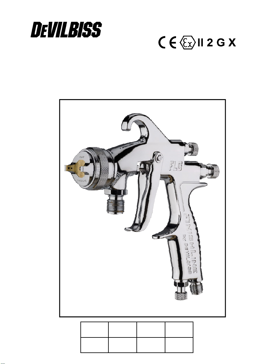
FLG-P5-14
Transtech Pressure-feed Spray Gun
E
E
D
D
1 – 8
16 – 22
F
F
NL
NL
9 – 15
23 – 30
EE
Operation Manual
FLG5 – Pressure-Feed Spray Gun
Important
Read and follow all instructions and Safety warnings before using this
equipment
Description
The FLG5 pressure feed Spraygun is fitted with a 1.4mm Nozzle for use with common
coating materials. A 1.1mm Nozzle and Needle is available as an alternative. The
FLG5 Spraygun is approved to ATEX regulations 94/9/EC, protection level;
II 2 G X. Suitable for use in Zones 1 and 2
Important: These spray guns are suitable for use with both water-based and solvent-
based coating materials. The design uses EPA compliant atomising (Devilbiss TransTech®) technology to reduce overspray and improve coating efficiency. Nozzles and
needles are manufactured in stainless steel. These guns are not designed for use with
highly corrosive and/or abrasive materials and if used with such materials it must be
expected that the need for cleaning and/or replacement of parts will be increased. If
there is any doubt regarding the suitability of a specific material contact your local
Distributor or ITW Finishing direct.
SPECIFICATION
Air supply connection – Universal 1/4 BSP and NPS
Maximum static air inlet pressure – P
Nominal gun inlet pressure with gun triggered – 2.4 bar (35 psi)
Maximum Service temperature – 40°C
Gun Weight – 930g
Airflow – 277 l/min (9.8 cfm)
Materials of Construction
Gun body – Aluminium. Stainless steel fluid passages
Nozzle – Stainless steel
Needle – Stainless Steel
ITW Finishing Systems and Products reserve the right to modify equipment specification without prior notice.
© 2005 ITW Finishing Systems and Products
2
= 12 bar (175 psi)
1

SAFETY WARNINGS
EE
Fire and explosion
Solvents and coating materials
can be highly flammable or
combustible when sprayed. ALWAYS
refer to the coating material suppliers
instructions and COSHH sheets
before using this equipment
Users must comply with all local
and national codes of practice
and insurance company
requirements governing
ventilation, fire precautions, operation
and house-keeping of working areas
This equipment, as supplied,
is NOT
Halogenated Hydrocarbons
cleaning non- conductive parts with
cloths. To prevent ignition sources from
static discharges, earth continuity must
be maintained to the spraygun and other
metallic equipment used. It is essential to
use conductive air and/or fluid hoses.
suitable for use with
Static Electricity can be
generated by fluid and/or air
passing through hoses, by the
spraying process and by
.
Personal Protective
Equipment
Toxic vapours – When sprayed,
certain materials may be
poisonous, create irritation or be
otherwise harmful to health.
Always read all labels and safety data
sheets for the material before spraying
and follow any recommendations. If In
Doubt, Contact Your Material Supplier
The use of respiratory protective
equipment is recommended at all
times. The type of equipment
must be compatible with the
material being sprayed.
Always wear eye protection
when spraying or cleaning the
spraygun
Gloves must be worn when
spraying or cleaning the
equipment
Training – Personnel should be given
adequate training in the safe use of
spraying equipment.
Misuse
Never aim a spraygun at any part of the
body
Never exceed the max. recommended
safe working pressure for the equipment
The fitting of non-recommended or nonoriginal spares may create hazards
Before cleaning or maintenance, all
pressure must be isolated and relieved
from the equipment
The product should be cleaned using a
gun washing machine. However, this
equipment should not be left inside gun
washing machines for prolonged periods
of time.
Noise Levels
The A-weighted sound level of
sprayguns may exceed 85 dB (A)
depending on the set-up being
used. Details of actual noise
levels are available on request. It is
recommended that ear protection is worn
at all times when spraying.
Operating
Spray Equipment using high pressures
may be subject to recoil forces. Under
certain circumstances, such forces could
result in repetitive strain injury to the
operator.
3
© 2005 ITW Finishing Systems and Products
EE
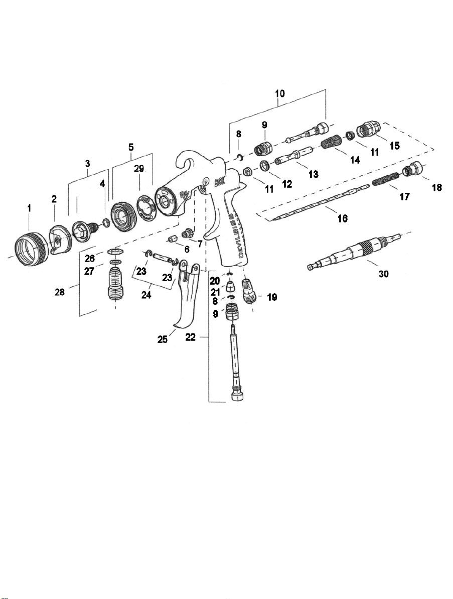
Ref. No Part Number Description
1 SGK-0023 Retaining ring 1
2 FLG-1-5 Air cap 1
3 SGK-0014-14 Fluid tip 1.8mm 1
● 4 - Gasket 1
● 5 K-5032- Sprayhead Kit 1
6 - Packing 1
7 - Packing gland nut 1
8 - Circlip 1
9 - Spray pattern adjustment valve bushing 1
10 - Spray pattern valve 1
11 - U-cup seal 2
12 - Air-valve seat 1
13 - Air-valve stem 1
14 - Air-valve spring 1
15 - Air-valve bushing 1
16 SGK-430-14 Fluid needle 1.8mm 1
17 - Fluid needle spring 1
18 - Fluid adjustment knob 1
19 - Nipple 1
20 - Circlip 1
21 - Air adjusting valve head 1
22 - Air adjusting valve assembly 1
23 - Circlip 1
24 - Trigger pin assembly 1
25 - Trigger 1
26 - Nut 1
27 - Washer 1
28 - Nipple assembly fluid 1
● 29 - Gasket 1
30 - Assembly Tool 1
K-5044
● K-5030: Baffle replacement kit, items 4 and 5.
© 2005 ITW Finishing Systems and Products
Seal, baffle and gasket replacement kit, items 4, 5, 6, 11, 12, 13, 14,
and 30
4
5
© 2005 ITW Finishing Systems and Products
EE
Installation
Important: To ensure that this equipment
reaches you in first class condition,
protective coatings have been used. Flush
the equipment through with a suitable
solvent before use.
1. Attach air hose to connector (19).
Recommended hose size 8 mm bore.
Operation
1. Mix coating material to manufacturers
instructions.
2. Turn needle adjusting screw (18)
clockwise to prevent movement.
3. Turn spreader valve (10) counterclockwise to fully open.
4. Adjust inlet air pressure (For
recommended figures see
Specifications) at the gun inlet with the
gun triggered. (pressure gauge
attachment shown under Accessories is
recommended for this).
5. Turn needle adjusting screw counter
clockwise until first thread shows.
6. Test spray. If the finish is too dry reduce
airflow by reducing air inlet pressure or
by the Airflow Valve (22). Screw the
Adjusting Knob in to reduce pressure.
The hose must be conductive and
electrical bond from the spraygun to
earth should be checked with an
ohmeter. A resistance of less than 10
Ohms is recommended.
2. Attach fluid supply hose to Fluid Inlet
(28).
7. If finish is too wet reduce fluid flow by
turning needle screw (18) clockwise or
reducing the fluid pressure. If
atomisation is too coarse, increase inlet
air pressure. If too fine reduce inlet
pressure.
8. The pattern size can be reduced by
turning adjusting valve (10) clockwise.
9. Hold gun perpendicular to surface being
sprayed. Arcing or tilting may result in
uneven coating.
10. The recommended spray distance is
150-200 mm (6”-8”).
11. Spray edges first. Overlap each stroke a
minimum of 50%. Move gun at a
constant speed.
12. Always turn off air and fluid supply and
relieve pressure when gun is not in use.
6
Preventative Maintenance
1. Turn off air and coating supply and
relieve pressure in the supply lines, or
if using QD system, disconnect from
airline and fluid line.
2. Remove air cap (1) & (2) and clean. If
any of the holes in the cap are blocked
with coating material use a toothpick to
clean. Never use metal wire which
© 2005 ITW Finishing Systems and Products
could damage the cap and produce
distorted spray patterns.
3. Ensure the tip of the nozzle (3) is clean
and free from damage. Build up of
dried paint can distort the spray
pattern.
4. Lubrication – stud (24), needle (16) and
air valve (13) should be oiled each day.
6

Replacement of Parts
Nozzle (3) and Needle (16) – Remove
parts in the following order: 18, 17, 16, 1,
2 and 3. Check condition of Nozzle Seal
(4) and replace if necessary. Replace any
worn or damaged parts and re-assemble
in reverse order. Recommended
tightening torque for nozzle (3) 16-20 Nm
(150-180 lbf in).
Packing – Remove parts 18, 17, 16.
Unscrew Packing Nut (7). Remove
packing (6). Fit new packing (6) and Nut
(7). Re-assemble parts 16, 17, and 18
and tighten Packing Nut (7) with spanner
sufficient to seal but to allow free
movement of needle. Lubricate with gun
oil.
Air Valve Seal Kit K-5040
1. Remove Adjusting Knob (18), Spring
(17), and Needle (16).
2. Loosen Housing (15).
3. Remove Housing (15) and Airvalve
Spring (14).
4. Remove Spindle (13).
5. Using Service Tool (40), engage
groove behind the Valve Seat (12)
and remove Valve Seat.
6. Push out the Front Airvalve Seal (11).
7. Turn the Gun upside down and let the
Seal fall out.
8. Fit New Front Seal (11) to Service
Tool.
9. Fit new Seal to gunbody and press
firmly to ensure Seal is engaged.
10. Fit New Valve Seat (12) to Service
Tool and fit Valve Seat into Gunbody.
11. Remove Rear Airvalve Seal (11) from
housing (15) with a hooked
instrument.
12. Fit new Seal to Service Tool and Fit
Seal to Housing (15).
13. Replace Spindle (13).
14. Replace Valve Spring (14), screw in
Housing (15) and tighten.
15. Screw reverse end of Service tool
into housing until fully engaged.
Tighten by hand to seat the Valve
Seat. Remove tool.
16. Fit Needle (16), Spring (17) and Knob
(18).
17. Adjust Needle Packing (7) with
Spanner sufficient to seal but to allow
free movement of needle. Lubricate
with gun oil.
Spreader valve (10) – Caution: always
ensure that the valve is in the fully open
position by turning screw fully counterclockwise before fitting to body.
Air cap / Nozzle Selection
Refer to coating material manufacturers
recommendations or ITW Finishing UK
Website:
www.itweuropeanfinishing.com
EE
Accessories
Cleaning Brush – order 4900-5-1-K3
Air adjusting valve and gauge – order HAV-501
Digital Pressure Gauge – DGI-501-BAR
Lubricant – order GL-1-K10
Drip free diaphragm – order KR-115-K5
Spraygun cleaning Kit – KK-4584
7
© 2005 ITW Finishing Systems and Products
EE
EC Declaration of Conformity
We: ITW Finishing UK, Ringwood Rd, Bournemouth, Dorset, BH11 9LH, UK, as the
Authorised Representative of the manufacturer of the Spraygun model FLG5, declare, under our
sole responsibility, that the equipment to which this document relates is in conformity with the
following standards or other normative documents:
BS EN 292-1 PARTS 1 & 2: 1991, BS EN 1953: 1999; and thereby conform to the
protection requirements of Council Directive 98/37/EC relating to Machinery Safety Directive,
and;
EN 13463-1:2001, council Directive 94/9/EC relating to Equipment and Protective
Systems intended for use in Potentially Explosive Atmospheres protection level II 2 GX.
This product also complies with the requirements of the EPA guidelines, PG6/34. Transfer
efficiency certificates are available on request.
B. Holt, General Manager
1st January 2006
© 2005 ITW Finishing Systems and Products
8
FF
Manuel d’utilisation
FLG5 – Pistolet à peinture sous pression
Important
Lire attentivement toutes les instructions et les Consignes de sécurité
avant d’utiliser ce matériel
Description
Le pistolet sous pression FLG5 est équipé d'une buse de 1,4 mm permettant
l'application des produits de revêtement courants. Une buse de 1,1 mm et une aiguille
sont disponibles en remplacement. Le pistolet FLG5 est conforme à la réglementation
ATEX 94/9/CE, niveau de protection :
II 2 G X, et convient à l’utilisation dans les Zones 1 et 2
Important : Ces pistolets peuvent être utilisés avec des produits à la fois à base
aqueuse et à base de solvant. La conception fait appel à une technologie de
pulvérisation (Devilbiss Trans-Tech®), conforme aux règles EPA, qui réduit les
retombées de pistolage et améliore le rendement en application. Les buses et les
aiguilles sont en acier inoxydable. Ces pistolets ne sont pas conçus pour l’utilisation
avec des produits fortement corrosifs et/ou abrasifs. S’ils sont utilisés avec de tels
produits, ils devront être nettoyés et/ou les pièces devront être remplacées plus
souvent. S’il y a le moindre doute en ce qui concerne le caractère approprié d’un
produit spécifique, contactez votre distributeur local ou ITW Finishing directement.
SPECIFICATIONS
Raccord d’alimentation d’air - Universel 1/4" BSP et NPS
Pression d’entrée d’air statique maximale - P
Pression d’entrée nominale du pistolet
quand la gâchette est actionnée - 2,4 bar (35 psi)
Température de service maximale - 40°C
Poids du pistolet - 930 g
Débit d’air - 277 l/min
Matières de construction
Corps du pistolet - Aluminium. Passages de liquide en acier inoxydable
Buse - Acier inoxydable
Aiguille - Acier inoxydable
ITW Finishing Systems and Products se réserve le droit de modifier les spécifications de ses produits sans préavis.
9
= 12 bar (175 psi)
1
© 2005 ITW Finishing Systems and Products
FF
CONSIGNES DE SECURITE
Incendie et explosion
Les solvants et produits de
revêtement peuvent être
extrêmement inflammables ou combustibles
lorsqu’ils sont pulvérisés. Se reporter
TOUJOURS
fournisseurs de produits et aux fiches
COSHH avant d’utiliser ce matériel.
ventilation, les précautions à prendre contre
l’incendie, le fonctionnement et la surveillance
des lieux de travail.
Ce pistolet, tel qu’il est fourni, n’est PAS
prévu pour l’utilisation avec des hydrocarbures halogénés.
avec des chiffons. Pour éviter de créer des
sources d’inflammation avec des décharges
statiques, la continuité à la terre doit être
maintenue avec le pistolet et tout autre
materiel métallique utilisé. Il est essentiel
d’utiliser des flexibles d’air et/ou de liquide
conducteurs.
aux instructions des
Les utilisateurs doivent se conformer à
tous les codes de pratique locaux et
nationaux et aux exigences des
compagnies d’assurance régissant la
De l’électricité statique peut être
produite par le liquide et/ou l’air qui
circule dans les flexibles, par le
processus de pulvérisation et par le
nettoyage de pièces non-conductrices
Équipement de protection
individuelle
Vapeurs toxiques – Lorsqu’ils sont
pulvérisés, certains produits peuvent
être toxiques, irritants ou
les étiquettes et les fiches signalétiques des
produits avant de les pulvériser, et respecter
les consignes de sécurité. En cas de doute,
contacter le fournisseur du produit.
être compatible avec le produit pulvérisé
généralement nocifs. Toujours lire
Il est recommandé d’utiliser un
appareil de protection respiratoire à
tout moment. Le type d’appareil doit
.
Toujours porter une protection
oculaire pour pulvériser ou nettoyer le
pistolet.
Porter des gants pour pulvériser ou
nettoyer le pistolet.
Formation – Le personnel doit être
correctement formé à l’utilisation sans risque
du pistolet.
Mauvaise utilisation
Ne jamais diriger le pistolet vers une
quelconque partie du corps.
Ne jamais excéder la pression de service
maximale recommandée pour le pistolet.
La pose de pièces détachées nonrecommandées ou qui ne sont pas d’origine
peut engendrer des risques.
Avant le nettoyage ou l’entretien, isoler et
évacuer la pression du pistolet.
Nettoyer le pistolet avec une machine
spécialement conçue à cet effet. Toutefois, ne
pas laisser le pistolet à l’intérieur de la
machine pendant une période prolongée.
Niveaux sonores
Le niveau sonore pondéré A des
pistolets de pulvérisation peut
dépasser 85 dB (A) selon la
configuration utilisée. Le détail des niveaux
sonores actuels est disponible sur demande.
Le port de protecteurs d’oreilles est
recommandé à tout moment pendant la
pulvérisation.
Utilisation
Le pistolet fonctionne sous hautes pressions
susceptibles de provoquer un effort de recul.
Dans certains cas, ces forces peuvent infliger
des microtraumatismes répétés à l’utilisateur.
© 2005 ITW Finishing Systems and Products
10
 Loading...