

SB-E-2-790
EE
1 – 7
FF
9 – 15
DD
16 – 22
NLNL
23 – 30
OPERATION MANUAL
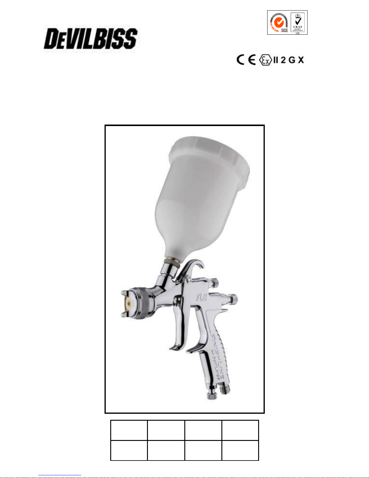
FLG-G5
Transtech Gravity Spraygun
ISS.06
2
© 2012 Finishing Brands UK Ltd.
Finishing Brands UK Limited reserves the right to modify equipment specification without prior notice.
Important
Read and follow all instructions and Safety warnings before using this
equipment
Description
The FLG5 Gravity Spraygun is fitted with a 1.4 or 1.8mm Nozzle for topcoat
applications. Alternative 2.0mm Nozzle and Needles are available for primer use. The
FLG5 Gravity Feed Spraygun is approved to ATEX regulations 94/9/EC, protection
level;
II 2 G X
Suitable for use in Zones 1 and 2
Important: These Sprayguns are suitable for use solvent based coating materials. The
design uses EPA compliant atomising (Devilbiss Trans-Tech®) technology to reduce
overspray and improve coating efficiency. Nozzles and Needles are manufactured in
Stainless Steel. These guns are not designed for use with highly corrosive and/or
abrasive materials and if used with such materials it must be expected that the need
for cleaning and/or replacement of parts will be increased. If there is any doubt
regarding the suitability of a specific material contact your local Distributor or Finishing
Brands UK Limited direct.
SPECIFICATION
Air supply connection – Universal 1/4 BSP and NPS
Maximum static air inlet pressure – P1 = 12 bar (175 psi)
Nominal gun inlet pressure with gun triggered – 2.4 bar (35 psi)
Maximum Service temperature – 40°C
Gun Weight – 640g
Airflow – 277 l/min (9.8 cfm)
Materials of Construction
Gun body - Aluminium
Nozzle - Stainless steel
Needle - Stainless Steel
Cup - Acetal and Stainless Steel
ENEN
Model Part Number
Example: FLG-G5-14
Nozzle Size
1.4 or 1.8
3
© 2012 Finishing Brands UK Ltd.
SAFETY WARNINGS
Fire and explosion
Solvents and coating materials
can be highly flammable or
combustible when sprayed. ALWAYS
refer to the coating material suppliers
instructions and COSHH sheets
before using this equipment.
Users must comply with all local
and national codes of practice
and insurance company
requirements governing
ventilation, fire precautions, operation
and house-keeping of working areas.
This equipment, as supplied,
is NOT suitable for use with
Halogenated Hydrocarbons.
Static Electricity can be
generated by fluid and/or air
passing through hoses, by the
spraying process and by
cleaning non- conductive parts with
cloths. To prevent ignition sources from
static discharges, earth continuity must
be maintained to the spraygun and other
metallic equipment used. It is essential to
use conductive air and/or fluid hoses.
Personal Protective
Equipment
Toxic vapours – When sprayed,
certain materials may be
poisonous, create irritation or be
otherwise harmful to health.
Always read all labels and safety data
sheets for the material before spraying
and follow any recommendations. If In
Doubt, Contact Your Material
Supplier.
The use of respiratory protective
equipment is recommended at all
times. The type of equipment
must be compatible with the
material being sprayed.
Always wear eye protection
when spraying or cleaning the
spraygun.
Gloves must be worn when
spraying or cleaning the
equipment.
Training – Personnel should be given
adequate training in the safe use of
spraying equipment.
Misuse
Never aim a spraygun at any part of the
body.
Never exceed the max. recommended
safe working pressure for the equipment
The fitting of non-recommended or nonoriginal spares may create hazards.
Before cleaning or maintenance, all
pressure must be isolated and relieved
from the equipment.
The product should be cleaned using a
gun washing machine. However, this
equipment should not be left inside gun
washing machines for prolonged periods
of time.
Noise Levels
The A-weighted sound level of
sprayguns may exceed 85 dB
(A) depending on the set-up
being used. Details of actual
noise levels are available on request. It
is recommended that ear protection is
worn at all times when spraying.
Operating
Spray Equipment using high pressures
may be subject to recoil forces. Under
certain circumstances, such forces could
result in repetitive strain injury to the
operator.

4
© 2012 Finishing Brands UK Ltd.
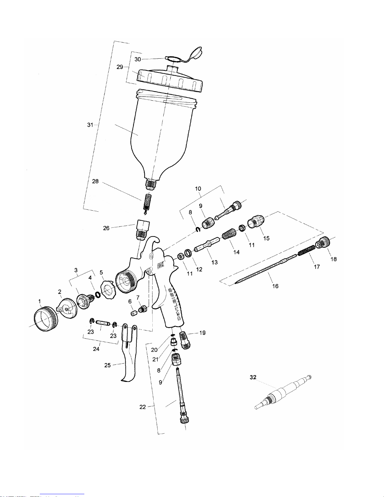
Ref. No Part Number Description Qty
1 SGK-0023 Retaining ring 1
2 FLG-0001-5 Air cap 1
3
SGK-0012-14
SGK-0014-18
SGK-0012-20
Fluid Tip 1.4mm
Fluid Tip 1.8mm
Fluid Tip 2.0mm (available separately)
1
● 4
- Gasket 1
● 5
- Baffle 1
6 - Packing 1
7 - Packing gland nut 1
8 - Retaining ring 1
9 - Spray pattern adjustment valve bushing 1
10 - Spray pattern valve 1
11 - U-cup seal 2
12 - Air valve seat 1
13 - Air valve stem 1
14 - Air valve spring 1
15 - Air valve bushing 1
16
SGK-0414
SGK-0418
SGK-0420
Fluid needle 1.4mm
Fluid needle 1.8mm
Fluid Needle 2.0mm (available separately)
1
17 - Fluid needle spring 1
18 - Fluid adjustment knob 1
19 - Nipple 1
20 - Retaining ring 1
21 - Air adjusting valve head 1
22 - Air adjusting valve assembly 1
23 - Retaining ring 1
24 - Trigger pin assembly 1
25 - Trigger 1
26 - Fluid nipple 1
28 KGP-5-K5 Filter 1
29 GFC-402 Lid assembly 1
30 GFC-2-K5 Drip free vent lid kit of 5 1
31 GFC-501 Cup assembly 1
32 - Assembly tool 1
K-5040: Seal, Baffle and gasket replacement kit, items 4, 5, 6, 11, 12, 13, 14 and 32
● K-5030: Baffle replacement kit, items 4 and 5.
5
© 2012 Finishing Brands UK Ltd.
6
© 2012 Finishing Brands UK Ltd.
Installation
Important: To ensure that this equipment
reaches you in first class condition,
protective coatings have been use. Flush
the equipment through with a suitable
solvent before use.
1. Attach air hose to connector (19).
Recommended hose size 8 mm bore.
The hose must be conductive and
electrical bond from the spraygun to
earth should be checked with an
ohmeter. A resistance of less than
106Ω is recommended.
2. Air supply should be filtered and
regulated.
Preventative Maintenance
1. Turn off air supply and relieve pressure
in the airline, or if using QD system,
disconnect from airline.
2. Empty coating material into a suitable
container and clean the gun and cup,
preferably in a gun wash machine.
3. IMPORTANT– the cup must not be
cleaned or rubbed with a dry cloth
or paper. It is possible to generate a
static charge, by rubbing, which if
discharged to an earthed object
could create an incendive spark and
cause solvent vapours to ignite.
Only use a dampened cloth or
antistatic wipes if additional
cleaning is required in a Hazardous
area.
4. Remove air cap (2) and clean. If any of
the holes in the cap are blocked with
coating material only use the Cleaning
Kit KK-4584 (see accessories) which
has the correct tools for this or a
toothpick to clean. Using any other tool
could damage the cap and produce
distorted spray patterns.
5. Ensure the tip of the nozzle is clean
and free from damage. Build up of
dried paint can distort the spray
pattern.
6. Lubrication – Trigger stud (24), needle
(16) and air valve spindle (13) should
be oiled each day.
Operation
1. Mix coating material to manufacturers
instructions
2. Turn needle adjusting screw (18)
counter-clockwise until first thread
shows
3. Turn pattern valve (10) counter-
clockwise to fully open
4. Adjust inlet air pressure to give 2.4 bar
(35 psi) at the gun inlet with the gun
triggered. (pressure gauge attachment
shown under Accessories is
recommended for this)
5. Test spray. If the finish is too dry reduce
airflow by reducing inlet pressure. If
finish is too wet reduce fluid flow by
turning needle screw (18) clockwise. If
atomisation is too coarse, increase inlet
air pressure. If too fine reduce inlet
pressure.
6. The pattern size can be reduced by
adjusting valve (10)
7. Hold gun perpendicular to surface being
sprayed. Arcing or tilting may result in
uneven coating.
8. The recommended spray distance is
150-200 mm (6”-8”).
9. Spray edges first. Overlap each stroke a
minimum of 50%. Move gun at a
constant speed.
10. Always turn off air supply and relieve
pressure when gun is not in use.
ENEN

7
© 2012 Finishing Brands UK Ltd.
Replacement of Parts
Accessories
Cleaning Brush – order 4900-5-1-K3
Pressure gauge Attachment – order HAV-501
Digital Pressure Gauge – DGIPRO-502-BAR
Lubricant – order GL-1-K10
Spraygun cleaning Kit – KK-4584
Nozzle (3) and Needle (16) – Remove
parts in the following order: 18, 17, 16, 1,
2 and 3. Check condition of Nozzle Seal
(4) and replace if necessary. Replace any
worn or damaged parts and re-assemble
in reverse order. Recommended
tightening torque for nozzle (3) 16-20 Nm
(150-180 lbf in).
Packing – Remove parts 18, 17, 16.
Unscrew Packing Nut (7). Remove
packing (6). Fit new packing (6) and Nut
(7). Re-assemble parts 16, 17, and 18
and tighten Packing Nut (7) with spanner
sufficient to seal but to allow free
movement of needle. Lubricate with gun
oil.
Air Valve Seal Kit (K-5040)
1. Remove Adjusting Knob (18), Spring
(17), and Needle (16).
2. Loosen Housing (15).
3. Remove Housing (15) and Airvalve
Spring (14).
4. Remove Spindle (13).
5. Using Service Tool (32), engage
groove behind the Valve Seat (12)
and remove Valve Seat.
6. Push out the Front Airvalve Seal
(11).
7. Turn the Gun upside down and let
the Seal fall out.
8. Fit New Front Seal (11) to Service
Tool.
9. Fit new Seal to Gunbody and press
firmly to ensure Seal is engaged.
10. Fit New Valve Seat (12) to Service
Tool and fit Valve Seat into
Gunbody.
11. Remove Rear Airvalve Seal (11)
from housing (15) with a hooked
instrument.
12. Fit new Seal to Service Tool and Fit
Seal to Housing (15).
13. Replace Spindle (13).
14. Replace Valve Spring (14), screw in
Housing (15) and tighten.
15. Screw reverse end of Service tool
into housing until fully engaged.
Tighten by hand to seat the Valve
Seat. Remove tool.
16. Fit Needle (16), Spring (17) and
Knob (18).
17. Adjust Needle Packing (7) with
Spanner sufficient to seal but to
allow free movement of needle.
Lubricate with gun oil.
Spreader valve (10) – Caution: always
ensure that the valve is in the fully open
position by turning screw fully counterclockwise before fitting to body.
Air cap / Nozzle Selection
Refer to coating material manufacturers
recommendations or Finishing Brands UK
Limited Website:
www.finishingbrands.eu
8
© 2012 Finishing Brands UK Ltd.
EC Declaration of Conformity
We: Finishing Brands UK Limited, Ringwood Rd, Bournemouth, Dorset, BH11 9LH, UK, as
the Authorised Representative of the manufacturer of the Spraygun model FLG5, declare, under
our sole responsibility, that the equipment to which this document relates is in conformity with the
following standards or other normative documents:
BS EN 292-1 PARTS 1 & 2: 1991, BS EN 1953: 1999; and thereby conform to the
protection requirements of Council Directive 98/37/EC relating to Machinery Safety Directive,
and;
EN 13463-1:2001, council Directive 94/9/EC relating to Equipment and Protective
Systems intended for use in Potentially Explosive Atmospheres protection level II 2 G X.
This product also complies with the requirements of the EPA guidelines, PG6/34. Transfer
efficiency certificates are available on request.
D. Smith, General Manager
13th September 2012
Finishing Brands UK Limited
ENEN
9
© 2012 Finishing Brands UK Ltd.
Finishing Brands UK Limited se réserve le droit de modifier les spécifications de ses produits sans préavis.
Manuel d’utilisation
FLG5 – Pistolet à gravité
Important
Lire attentivement toutes les instructions et les Consignes de sécurité
avant d’utiliser ce matériel
Description
Le pistolet à gravité FLG5 est équipé d’une buse de 1,4/1,8 mm pour l’application de
couches de finition. Une buse de 2,0 mm est également disponible pour les apprêts. Le
pistolet à gravité FLG5 est conforme à la réglementation ATEX 94/9/CE, niveau de
protection :
II 2 G X, et convient à l’utilisation dans les Zones 1 et 2
Important : Ces pistolets peuvent être utilisés avec des produits à base de solvant. La
conception fait appel à une technologie de pulvérisation (Devilbiss Trans-Tech®),
conforme aux règles EPA, qui réduit les retombées de pistolage et améliore le rendement
en application. Les buses et les aiguilles sont en acier inoxydable. Ces pistolets ne sont
pas conçus pour l’utilisation avec des produits fortement corrosifs et/ou abrasifs. S’ils sont
utilisés avec de tels produits, ils devront être nettoyés et/ou les pièces devront être
remplacées plus souvent. S’il y a le moindre doute en ce qui concerne le caractère
approprié d’un produit spécifique, contactez votre distributeur local ou Finishing Brands
UK Limited directement.
SPECIFICATIONS
Raccord d’alimentation d’air - Universel 1/4" BSP et NPS
Pression d’entrée d’air statique maximale - P1 = 12 bar (175 psi)
Pression d’entrée nominale du pistolet
quand la gâchette est actionnée - 2,4 bar (35 psi)
Température de service maximale - 40°C
Poids du pistolet - 640 g
Débit d’air - 277 l/min
Matières de construction
Corps du pistolet - Aluminium
Buse - Acier inoxydable
Aiguille - Acier inoxydable
Godet - Acétal et acier inoxydable
FF
Numéro de référence du modèle
Exemple : FLG-G5-14
Dimension de
la buse (1,4 /1,8)
 Loading...