

DeVilbiss FLG-CNG-115, FLG-HVG-315 Service Manual
SERVICE MANUAL
EN
GUN DESCRIPTION
The FLG4 is a light weight, general
purpose gravity feed spray gun for
spraying applications suitable for use with a wide
variety of common coating materials. Model
FLG-HVG-315 is an HVLP spray gun, and model
FLG-CNG-115 is conventional.
FLG4 GRAVITY FEED SPRAY GUN AND
DEKUPS® DISPOSABLE CUP SYSTEM
MODELS: FLG-CNG-115 AND FLG-HVG-315
SPECIFICATIONS
Maximum Air Pressure: 100 psi
Gun Body: Forged Aluminum
Fluid Path: Anodized Aluminum
Air Inlet: 1/4" NPS male
Gun Weight: 18.13 oz / 514 g
IMPORTANT! DO NOT DESTROY
It is the Customer's responsibility to have all operators and service personnel read and understand this manual.
Contact your local DeVilbiss representative for additional copies of this manual.
READ ALL INSTRUCTIONS BEFORE OPERATING THIS DEVILBISS PRODUCT.
SB-2-779-R1 (4/2018) 1 / 12 www.carlisleft.com

EN
SAFETY PRECAUTIONS
This manual contains information that is important for you to know and understand. This information relates to USER SAFETY and
PREVENTING EQUIPMENT PROBLEMS. To help you recognize this information, we use the following symbols. Please pay particular
attention to these sections.
NOTE
Important information that tells how
Important safety information – A hazard
that may cause serious injury or loss
of life.
to prevent damage to equipment,
or how to avoid a situation that may
cause minor injury.
The following hazards may occur during the normal use of this equipment.
Please read the following chart before using this equipment.
HAZARD CAUSE SAFEGUARDS
Fire
Solvent Spray
Inhaling Toxic Substances
Explosion Hazard Incompatible Materials
General Safety
Cumulative Trauma
Disorders ("CTD's")
CTD's, or musculoskeletal
disorders, involve damage
to the hands, wrists,
elbows, shoulders, neck,
and back. Carpal tunnel
syndrome and tendonitis
(such as tennis elbow or
rotator cuff syndrome) are
examples of CTD's.
Solvent and coatings can be highly flammable
or combustible especially when sprayed.
During use and while cleaning and flushing,
solvents can be forcefully expelled from fluid
and air passages. Some solvents can cause
eye injury.
Certain materials may be harmful if inhaled, or
if there is contact with the skin.
Halogenated hydrocarbon solvents - for
example; methylene chloride and 1,1,1, Trichloroethane are not chemically compatible
with the aluminum that might be used in many
system components. The chemical reaction
caused by these solvents reacting with
aluminum can become violent and lead to an
equipment explosion.
Improper operation or maintenance of
equipment.
Use of hand tools may cause cumulative
trauma disorders ("CTD's").
CTD's, when using hand tools, tend to affect the
upper extremities. Factors which may increase
the risk of developing a CTD include:
1. High frequency of the activity.
2. Excessive force, such as gripping, pinching,
or pressing with the hands and fingers.
3. Extreme or awkward finger, wrist, or arm
positions.
4. Excessive duration of the activity.
5. Tool vibration.
6. Repeated pressure on a body part.
7. Working in cold temperatures.
CTD's can also be caused by such activities
as sewing, golf, tennis, and bowling, to name
a few.
Adequate exhaust must be provided to keep air free of
accumulations of flammable vapors.
Smoking must never be allowed in the spray area.
Fire extinguishing equipment must be present in the spray area.
Wear eye protection.
Follow the requirements of the Material Safety Data Sheet
supplied by your coating material manufacturer.
Adequate exhaust must be provided to keep the air free of
accumulations of toxic materials.
Use a mask or respirator whenever there is a chance of inhaling
sprayed materials. The mask must be compatible with the
material being sprayed and its concentration. Equipment must
be as prescribed by an industrial hygienist or safety expert, and
be NIOSH approved.
Guns with stainless steel internal passageways may be used
with these solvents. However, aluminum is widely used in
other spray application equipment - such as material pumps,
regulators, valves, and this gun and cup. Check all equipment
items before use and make sure they can also be used safely
with these solvents. Read the label or data sheet for the material
you intend to spray. If in doubt as to whether or not a coating or
cleaning material is compatible, contact your material supplier.
Operators should be given adequate training in the safe use
and maintenance of the equipment (in accordance with the
requirements of NFPA-33, Chapter 15). Users must comply with
all local and national codes of practice and insurance company
requirements governing ventilation, fire precautions, operation,
maintenance, and housekeeping. These are OSHA Sections
1910.94 and 1910.107 and NFPA-33.
Pain, tingling, or numbness in the shoulder, forearm, wrist,
hands, or fingers, especially during the night, may be early
symptoms of a CTD. Do not ignore them. Should you experience
any such symptoms, see a physician immediately. Other early
symptoms may include vague discomfort in the hand, loss of
manual dexterity, and nonspecific pain in the arm. Ignoring early
symptoms and continued repetitive use of the arm, wrist, and
hand can lead to serious disability. Risk is reduced by avoiding
or lessening factors 1-7.
Information that you should pay special
attention to.
CA PROP
65
PROP 65 WARNING
WARNING: This product contains
chemicals known to the State of
California to cause cancer and birth
defects or other reproductive harm.
SB-2-779-R1 (4/2018)2 / 12www.carlisleft.com

FLG4 GRAVITY FEED SPRAY GUN AND DeKUPS® DISPOSABLE CUP SYSTEM
EN
IMPORTANT: Before using this
equipment, read all safety precautions
on page 2 and instructions. Keep for
future use.
Halogenated hydrocarbon
solvents - for example; 1, 1, 1trichloroethane and methylene
chloride - can chemically react
with the aluminum in this gun
and cause an explosion hazard.
Read the label or data sheet for the
material you intend to spray. Do
not use spray materials containing
these solvents with this spray gun.
IMPORTANT: This gun may be used with
most common coating and finishing
materials. It is designed for use with mildly
corrosive and non-abrasive materials.
If used with other high corrosive or
abrasive materials, it must be expected
that frequent and thorough cleaning will
be required and the necessity for replacement
of parts will be increased.
HVLP MODELS ONLY:
HVLP models of this gun were manufactured
to provide maximum transfer efficiency by
limiting air cap pressure to 10 psi (complies
with rules issued by SCAQMD and other air
quality authorities).
HVLP models of this gun will produce
approximately 10 psi cap pressure at 23 psi
gun inlet pressure, as measured at the gun
inlet. An air cap test kit (see Accessories)
should be used to ensure 10 psi cap pressure
is not exceeded.
The No. 3 (HVLP) air cap requires a 14 scfm
air supply at the gun inlet of 23 psi max.,
measured with the trigger pulled.
CONVENTIONAL MODELS ONLY:
The No. 1 air cap requires 10 scfm air supply
at a gun inlet of 40 psi, measured with the
trigger pulled.
INSTALLATION
Note
Protective coating and rust
inhibitors have been used to keep
the gun in good condition prior to
shipment. Before using the gun,
flush it with solvents so that these
materials will be removed from
fluid passages.
For maximum transfer efficiency, do not
use more pressure than is necessary to
atomize the material being applied.
Connect the gun to a clean, moisture and oil
free air supply using a hose size of at least
5/16" I.D. hose. Do not use 1/4" I.D. hose.
(25' x 1/4" hose at 18 CFM has a pressure
loss of 25 psi. 25' x 5/16" hose at 18 CFM
has a pressure loss of 8 psi.)
Note
Depending on hose length, larger
I.D. hose may be required. Install
an HAV-501 air gauge at the gun
handle and air cap test kit over tip.
When gun is triggered on, adjust
regulated pressure to desired
setting to provide a maximum of
10 psi at the air cap. Do not use
more pressure than is necessary
to atomize the material being
applied. Excess pressure will
create additional overspray and
reduce transfer efficiency.
Note
If quick connects are required,
use only high flow quick connects
approved for HVLP use, such as
DeVilbiss HC-4419 and HC-4699.
Other types will not allow enough
air flow for proper gun operation.
Note
If an air adjusting valve is used
at the gun inlet, use DeVilbiss
Model HAV-500 or HAV-501. Some
competitive adjusting valves
have significant pressure drop
that can adversely affect spray
performance. Models HAV-500 and
HAV-501 have minimal pressure
drop, which is important for HVLP
spraying.
OPERATION
Mix, prepare and strain the material to
be sprayed according to the paint
maufacturer's instructions.
Strain material through a 60 or 90 mesh
screen.
PAINTING
Open the spreader adjustment valve (5) (Fan)
by turning the valve stem counterclockwise.
Close the fluid needle adjusting knob (6) by
turning clockwise.
Turn on air supply and set gun inlet
pressure; 23 psi for HVLP, 40 psi for
conventional use. Some materials can be
sprayed at lower pressures, improving
transfer efficiency.
Spray a test area. Turn the fluid needle
adjusting knob (6) counterclockwise until a
full coat is obtained.
If the finish is too sandy and dry, the
material flow may be too low for the
atomization air pressure being used.
Turn the fluid needle adjusting knob (6)
counterclockwise to increase fluid flow.
If the finish sags, there is too much material
flowing for the atomization air pressure
being used. Turn the fluid needle adjusting
knob (6) clockwise to decrease fluid flow.
Pattern width can be altered by turning
spreader adjustment valve (5), either
clockwise to decrease the width or
counterclockwise to increase the width.
Adjust inlet air pressure to provide a uniform
dispersion of atomized paint throughout
the pattern. Keep air pressure as low as
possible to minimize bounce-back and
overspray. Excessive pressure will result in
split spray patterns. Inadequate pressures
will cause heavy centered patterns and poor
atomization.
SB-2-779-R1 (4/2018) 3 / 12 www.carlisleft.com
(continued on page 4)
EN
FLG4 GRAVITY FEED SPRAY GUN AND DeKUPS® DISPOSABLE CUP SYSTEM
CLEANING
To clean air cap and fluid tip, brush exterior
with a stiff bristle brush. If necessary to clean
cap holes, use a broom straw or toothpick
if possible. If a wire or hard instrument is
used, extreme care must be used to prevent
scratching or burring of the holes which will
cause a distorted spray pattern.
To clean fluid passages, remove excess
material at source, then flush with a
suitable solvent. Wipe gun exterior with a
solvent dampened cloth. Never completely
immerse in solvent as this is detrimental to
the lubricants and packings.
PREVENTIVE MAINTENANCE
Spray Gun Lubrication
Daily, apply a drop of SSL-10 spray gun lube
at trigger bearing stud (10) and the stem
of the air valve (8). The shank of the fluid
needle (7) where it enters the packing nut
(7) should also be oiled. The fluid needle
packing (7) should be kept soft and pliable by
periodic lubrication. Make sure the baffle (4)
and retaining ring (1) threads are clean and
free of foreign matter. Before assembling
retaining ring to baffle, clean the threads
thoroughly, then add two drops of SSL-10
spray gun lube to threads. The fluid needle
spring (6) and air valve spring (8) should
be coated with a very light grease, making
sure that any excess grease will not clog
the air passages.
PARTS REPLACEMENT
Note
When replacing the fluid tip or
fluid needle, replace both at the
same time. Using worn parts can
cause fluid leakage. Also, replace
the needle packing and fluid tip
seal at this time. Lightly lubricate
the threads of the fluid tip before
reassembling. Torque to 15-20 ftlbs. Do not overtighten the fluid tip.
The fluid tip part number and tip size are
stamped around the outside of the fluid tip.
See Chart 1 for selecting the proper size
fluid tip for the material you are spraying.
To prevent damage to the fluid
tip (2) or fluid needle (7), be sure
to either:
1. Pull the trigger and hold while
tightening or loosening the
fluid tip; or
2. Remove fluid needle adjusting
screw (6) to relieve spring
pressure against needle collar.
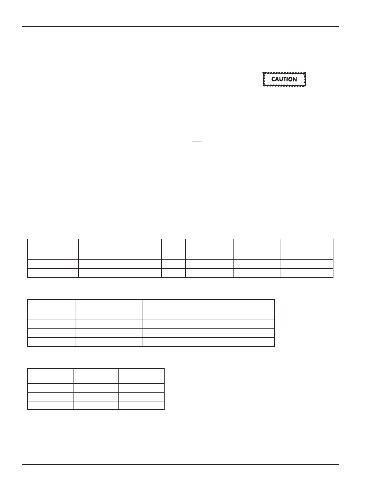
Chart 1 – FLG4 HVLP and Conventional Models, Gravity Feed
Spray Gun
Model Number
FLG-CNG-115 Gravity – Conventional 1 FLG4-1-1-k FLG-332-15K 1.5 mm
FLG-HVG-315 Gravity – HVLP 3 FLG4-1-3-K FLG-332-15K 1.5 mm
Chart 2 – Fluid Tips
Fluid Tip & Seal
(Ref. No. 2)
Part No.
FLG-332-13K 0.051 1.3 Stains, lacquers, basecoats, clears.
FLG-332-15K 0.059 1.5 General purpose, light to medium viscosity material.
FLG-332-22K 0.086 2.2 Medium viscosity materials.
Chart 3 – HVLP Air Flows (#3 Cap)
Inlet Pressure
(PSI)
15 10 6
19 11.5 8
23 13.5 10
Fluid Tip
Size
(in.)
Air Flow
(SCFM)
Application Type
Fluid Tip
Size
(mm)
Cap Presure
Applications
(PSI)
Number
on
Air Cap
Air Cap Kit
(Ref. No. 1)
Fluid Tip
(Ref. No. 2)
Fluid Tip Size
Supplied With Gun
SB-2-779-R1 (4/2018)4 / 12www.carlisleft.com
 Loading...