

DeVilbiss FLG-692, FLG-693, FLG-694 Instructions Manual
SERVICE BULLETIN
SB-2-616-B
Replaces SB-2-616-A
Gun Repair Kit FLG-488
FLG3 SPRAY GUNS, SIPHON AND PRESSURE FEED
MODELS: FLG-692, FLG-693 AND FLG-694
IMPORTANT: Before using this equipment, read all safety
precautions on page 2 and instructions. Keep for future use.
DESCRIPTION
The FLG-693 and FLG-694 are light weight, general purpose suction
feed spray guns for both conventional and HVLP spraying applications suitable for use with a wide variety of common coating
materials. These models include the TGC-545 suction cup. The
FLG-692 is a pressure feed HVLP spray gun.
Halogenated hydrocarbon solvents - for example; 1, 1, 1trichloroethane and methylene chloride - can chemically
react with the aluminum in this gun and cause an explosion hazard. Read the label or data sheet for the material
you intend to spray. Do not use spray materials containing these solvents with this spray gun.
IMPORTANT: This gun may be used with most common coating
and finishing materials. It is designed for use with mildly corrosive
and non-abrasive materials. If used with other high corrosive or
abrasive materials, it must be expected that frequent and thorough cleaning will be required and the necessity for replacement
of parts will be increased.
OPERATION
Strain material thru 60 or 90 mesh screen.
Model FLG-693:
The No. 1 (conventional) air cap requires an air supply at the gun
inlet of approximately 45 psi, measured with the trigger pulled
and can be operated from a 3 H.P. compressor.
HVLP Models FLG-692 and FLG-694:
The No. 3 (HVLP) air cap requires an air supply at the gun inlet of
23 psi max., measured with the trigger pulled.
This gun was manufactured to provide maximum transfer efficiency
by limiting air cap pressure to 10 psi (complies with rules issued by
SCAQMD and other air quality authorities).
This gun will produce approximately 10 psi cap pressure at 23 psi
inlet pressure, as measured at the gun inlet. An air cap test kit (see
ACCESSORIES) should be used to insure 10 psi cap pressure is not
exceeded.
Adjust fluid pressure to deliver the desired paint volume. Adjust air
pressure and fluid flow to provide a uniform dispersion of atomized
paint throughout the pattern. Keep air pressure as low as possible
to minimize bounce - back and overspray. Excessive air pressure
will result in split patterns. Low air pressure will result in heavy
centered patterns and poor atomization. Excessive fluid flow will
result in heavy center spray patterns. Inadequate fluid flows may
cause the pattern to split. See Spray Gun Guide, SB-2-001, which is
available upon request, for details concerning set up of spray guns.
To hang the spray gun when not using, refer to the "Accessories"
page 8 (192219 or GH-407).
PREVENTIVE MAINTENANCE
To clean air cap and fluid tip, brush exterior with a stiff bristle brush.
If necessary to clean cap holes, use a broom straw or toothpick if
possible. If a wire or hard instrument is used, extreme care must
be used to prevent scratching or burring of the holes which will
cause a distorted spray pattern.
To clean fluid passages, remove excess material at source, then
flush with a suitable solvent. Wipe gun exterior with a solvent
dampened cloth. Never completely immerse in solvent as this
is detrimental to the lubricants and packings.
When replacing the fluid tip or fluid needle, replace
the same time. Using worn parts can cause fluid leakage.
To prevent damage to the fluid tip (3) or fluid needle (11), be
sure to either 1) pull the trigger and hold while tightening or
loosening the fluid tip or 2) remove fluid needle adjusting knob
(13) to relieve spring pressure against needle collar.
Spray Gun Lubrication
Daily, apply a drop of SSL-10 spray gun lube at trigger bearing stud
(21) and the stem of the air valve (14). The shank of the fluid needle
(11) where it enters the packing nut (24) should also be oiled. The fluid
needle packing (23) should be kept soft and pliable by periodic
lubrication. Make sure the baffle (6) and retaining ring (1) threads are
clean and free of foreign matter. Before assembling retaining ring to
baffle, clean the threads thoroughly, then add two drops of SSL-10
spray gun lube to threads. The fluid needle spring (12) and air valve
spring (15) should be coated with a very light grease, making sure
that any excess grease will not clog the air passages. For best results,
lubricate the points indicated, daily.
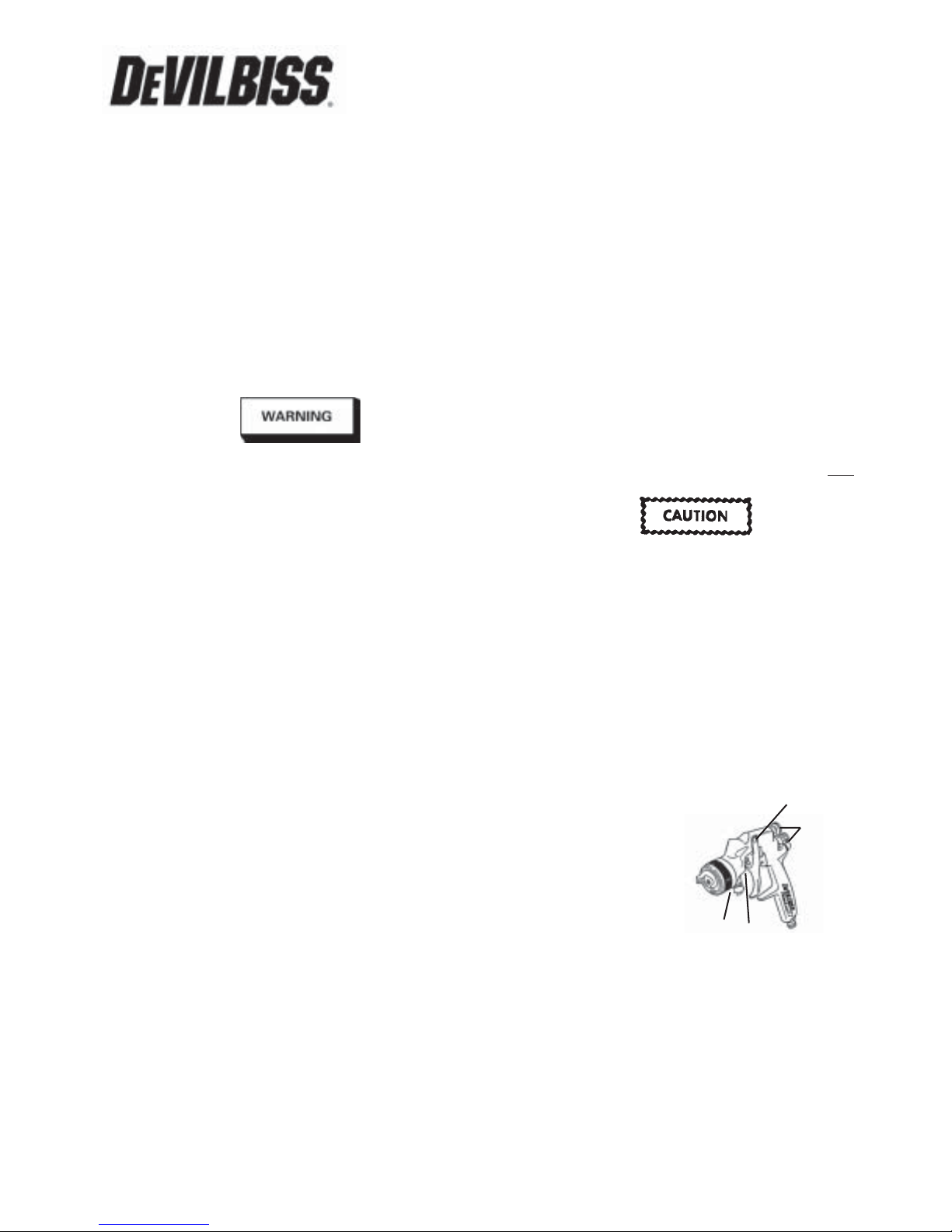
A. Trigger Points
B. Packing
C. Adjusting Valves
D. Baffle Threads
DESCRIPTION - MODEL TGC-545 CUP
This one quart capacity drip free suction cup has a unique, two
position valve which permits selection of either a drip free spraying
mode or a conventional open vent mode.
In the drip free position, air is directed through the vent in the lid to
a channel beneath the lid gasket before entering the cup at the valve.
This allows the cup to be tilted when full without dripping paint
through the vent.
The open position isolates the channel and opens a direct vent into
the cup.
Note
Figure 1
both at
A
C
D
B
(Continued on page 3)
Page 2 SB-2-616-B
SAFETY PRECAUTIONS
This manual contains information that is improtant for you to know and understand. This information relates to USER SAFETY and
PREVENTING EQUIPMENT PROBLEMS. To help you recognize this information, we use the following symbols. Please pay particular attention
to these sections.
Note
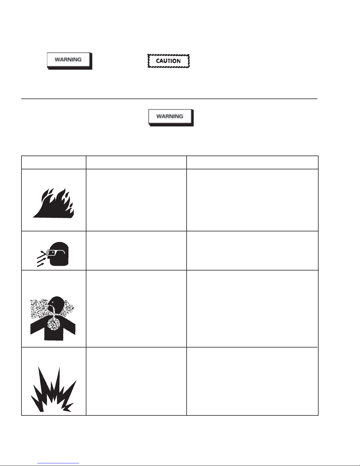
Important safety information - A hazard
that may cause serious injury or loss of
life.
The following hazards may occur during the normal use of this equipment.
HAZARD CAUSE SAFEGUARDS
Fire
Solvent Spray
Please read the following chart before using this equipment.
Solvent and coatings can be highly flam- Adequate exhaust must be provided to keep air free of
mable or combustible especially when accumulations of flammable vapors.
sprayed.
During cleaning and flushing, solvents can Wear eye protection.
be forcefully expelled from fluid and air
passages. Some solvents can cause eye
injury.
Important information that tells how to
prevent damage to equipment, or how
to avoid a situation that may cause
minor inury.
Smoking must never be allowed in the spray area.
Fire extinguishing equipment must be present
in the spray area.
Information that you should pay
special attention to.
Inhaling Toxic
Substances
Explosion Hazard Incompatible Materials
Certain materials may be harmful if Follow the requirements of the Material Safety Data
inhaled, or if there is contact with the skin. Sheet supplied by your coating material manufacturer.
Adequate exhaust must be provided to keep the
air free of accumulations of toxic materials.
Use a mask or respirator whenever there is a chance of
inhaling sprayed materials. The mask must be compatible
with the material being sprayed and its concentration.
Equipment must be as prescribed by an industrial
hygienist or safety expert, and be NIOSH approved.
Halogenated hydrocarbon solvents - for Guns with stainless steel internal passageways may be
example; methylene chloride and 1, 1, 1 - used with these solvents. However, aluminum is widely
Trichlorethylene are not chemically com- used in other spray application equipment - such as
patible with the aluminum that might be material pumps, regulators, valves, and this gun and cup.
used in many system components. The Check all equipment items before use and make sure they
chemical reaction caused by these solvents can also be used safely with these solvents. Read the
reacting with aluminum can become violent label or data sheet for the material you intend to spray.
and lead to an equipment explosion. If in doubt as to whether or not a coating or cleaning
material is compatible, contact your material supplier.
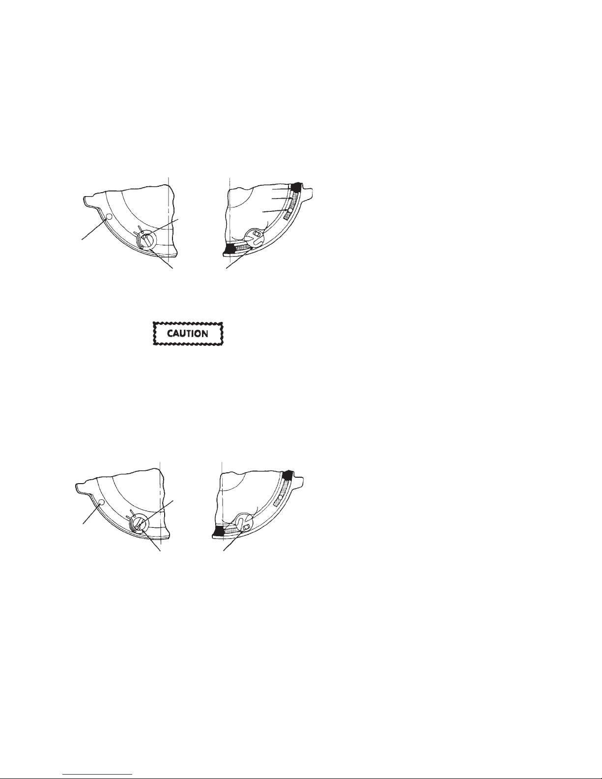
The position of the valve is indicated by alignment of the hole in the
valve slot with the marks cast on the lid. These positions are
identified as on the lid as "O" for vent open and "D/F" for drip free.
OPERATION
Open Vent Mode "O" - To operate in the open vent mode, rotate the
valve with a screwdriver or coin so that the hole in the valve slot is
aligned with the "O" on the lid. See Figure 2.
If the valve slot hole should plug while operating in the "O" vent
mode, use a pointed tool such as a nail or drill bit to probe through
the valve slot hole to clear away the obstruction.
Figure 2 - Open Vent Mode
Lid UndersideLid Top
Gasket
Channel
Channel
Vent
Hole
Gasket shown
partially removed
Channel
Vent Hole
(Do Not Probe)
O
D/F
Valve in Open Position
Valve slot
hole can be
probed to
clean.
Drip Free Mode "D/F" - To operate in the drip free mode, rotate the
valve with a screwdriver or coin so that the hole in the valve slot is
aligned with the "D/F" on the lid. See Figure 3.
Do not probe through the valve slot hole while the valve
is in D/F position. These holes are sealed by lid gasket and
damage could result. See Figs. 2 & 3.
Valve Movement
Do not forcibly rotate the valve. If it will not move freely, soak in
solvent or remove the lid assembly from the cup and press down on
the top of the valve until it breaks free. The valve has free travel
vertically of about 1/8". This can be used to push out the lid gasket.
Figure 3 - Drip Free Mode
Lid Top
Valve slot
hole sealed (Do Not Probe)
Channel
Vent Hole
(Do Not Probe)
D/F
O
Valve in Drip Free Position
INSTALLATION
1. Position yoke at right angle to gun body with vent hole in lid
toward rear and lever of cam (29) toward front of gun.
2. Fasten cup lid assembly to gun by attaching nut (28), see
Figure 5, to fluid inlet nipple on gun. Tighten nut with wrench
only until snug.
3. Strain material to be sprayed through a 60-90 mesh screen
before pouring into cup.
4. Engage pins on cup into yoke and tighten yoke by moving
lever of cam clockwise.
MAINTENANCE
Lid Repair/Replacement:
1. To replace a damaged part, use a 5/16" Allen wrench to loosen
and remove adapter (27), nut (28) and yoke and cam (29). Lid
and tube assembly are now loose for replacement.
2. Replace damaged parts on the lid and tube assembly. The cam
lever should be located on opposite side of lid from valve (30).
Lid Underside
Gasket shown
partially removed
SB-2-616-B Page 3
3. Apply sealant (Loctite #262) to the first two full threads of
adapter. Insert threaded end of adapter (27) into open end of
nut (28).
4. Install adapter (27) and nut (28) in top of lid and tube assembly.
Use a 5/16" Allen wrench to tighten firmly (10-12 foot pounds).
Valve and Lid Gasket Replacement:
1. To remove a damaged valve (30) or lid gasket (31), press down
on top of valve until it breaks free.The valve pushes the lid
gasket from the seat. The lid gasket may now be removed from
the lid. Continue pressing hard on the valve to remove it from
the lid.
2. Install replacement valve (30) through bottom of lid so that the
valve tab is toward center of lid. Snap in place. If necessary,
use a plastic mallet or screwdriver handle to tap the valve in
place. Press the lid gasket (31) firmly in the lid using the end of
a crescent wrench handle. Insert the side with the black marks
first.
CLEANING
General: For routine cleaning, it is not necessary to remove the lid
gasket. It is not necessary or desirable to remove the valve for any
cleaning procedure. The valve can be depressed from the outside
to assist in removal of the gasket for gasket replacement or when
cleaning dried paint from the channel. The valve should not be
forced past the shoulder which retains it in the lid except for
replacement.
The cam and mating surfaces on the lid and yoke normally don't
require removal for cleaning. Spraying some materials containing
Teflon® or similar materials can necessitate more frequent cleaning
and possible disassembly of the cam. The overspray containing
Teflon® can build up on the cam and mating surfaces causing a
condition where the cam may loosen during use.
Note
Clean cam and mating surface on lid with a solvent soaked
Scotch™ pad and blow dry. If cam loosening persists,
removal of the yoke and cam will be required for more
thorough cleaning of these parts. Again, use a solvent
soaked Scotch™ pad for this purpose. Reassemble lid.
Air Pressure: Always clean with reduced air pressure. An air
pressure no greater than 15 to 20 psi will allow quick and thorough
cleaning of the cup and gun and at the same time will:
1. Minimize the amount of solvent atomized into the air.
2. Prevent possibility of damage to cup from excessive back
pressure.
3. Reduce the force with which solvent is expelled from the vent.
Cleaning Procedures:
1. Empty paint from cup and add small amount of clean solvent.
The amount required will vary with different coatings and
solvents.
2. Shake cup to wash down inside surfaces. Then spray solvent
at low air pressure (15-20 psi) to flush out fluid passages.
3. Pour out solvent and add same amount of clean solvent.
4a. Again, shake cup. Loosen air cap. Hold a folded cloth over
front of gun and invert cup over solvent receptacle. Trigger
with short bursts to back flush vent channel. With valve in the
D/F position, solvent will be expelled with force from the
channel vent hole in lid.
Alternative to Step 4a.
4b. Shut off air to gun. With valve in the D/F position, invert cup
over solvent receptacle. Trigger gun. Allow solvent to drip out
channel vent hole in lid for several seconds, or until clean
solvent is seen.
IMMERSION
Since all materials in the cup are highly solvent resistant, the cup
assembly may be immersed for cleaning. Immersion should not
exceed 24 hours. The use of paint strippers should be avoided
because strippers will affect the aluminum as well as other nonmetallic components. If the lid gasket has become swollen from
prolonged exposure to solvents, it will return to its original size
without loss of properties when allowed to dry.
 Loading...