

DeVilbiss FinishLine FLG-611-114, FinishLine FLG-611-212, FinishLine FLG-611-318 Operation Manuals
Page 1
Operation Manual:
CONVENTIONAL AND HVLP GRAVITY FEED
SPRAY GUN AND CUP OUTFITS
Important:
Read and follow all instructions and SAFETY PRECAUTIONS
before using this equipment
The FLG-611 and FLG-631 are lightweight, general purpose spray guns for both conventional and HVLP spraying applications
suitable for use with a wide variety of common coating materials.
The No.1 (conventional) air cap on the FLG-611 requires an air supply at gun inlet of approximately 45 psi and can be
operated from a 3 hp compressor. The No.2 (conventional) air cap on the FLG-611 requires an air supply at the gun of
approximately 40 psi and can be operated from a 1-1/2 - 2 hp compressor. The No.3 (HVLP) air cap on the FLG-631 requires
a maximum of 23 psi gun inlet pressure, and can be operated from a 3 hp air compressor.
Products shown here are covered by US patent number 5,803,367.
IMPORTANT: These guns may be used with most common coating and finishing materials. They are designed for use with
mildly corrosive or non abrasive materials. If used with other high corrosive or abrasive materials, it must be expected that
frequent and thorough cleaning will be required and the necessity for replacement of parts will be increased.
FLG-611 Conventional Gravity Feed Gun and Cup Outfit
FLG-631 HVLP Gravity Feed Gun and Cup Outfit
Maximum recommended working pressure: 100 psi
Air inlet threads :
1
¼4" NPS(M)
Materials in contact with coating materials
Fluid tip material : Polyarylamide
Fluid inlet threads : Stainless steel.
Fluid needle : Stainless steel.
HVLP models : 23 psi air inlet pressure (with trigger pulled) delivers 10 psi air cap pressure
SPECIFICATIONS
MODELS
DESCRIPTION
SB-US-2-579-C
Page 2
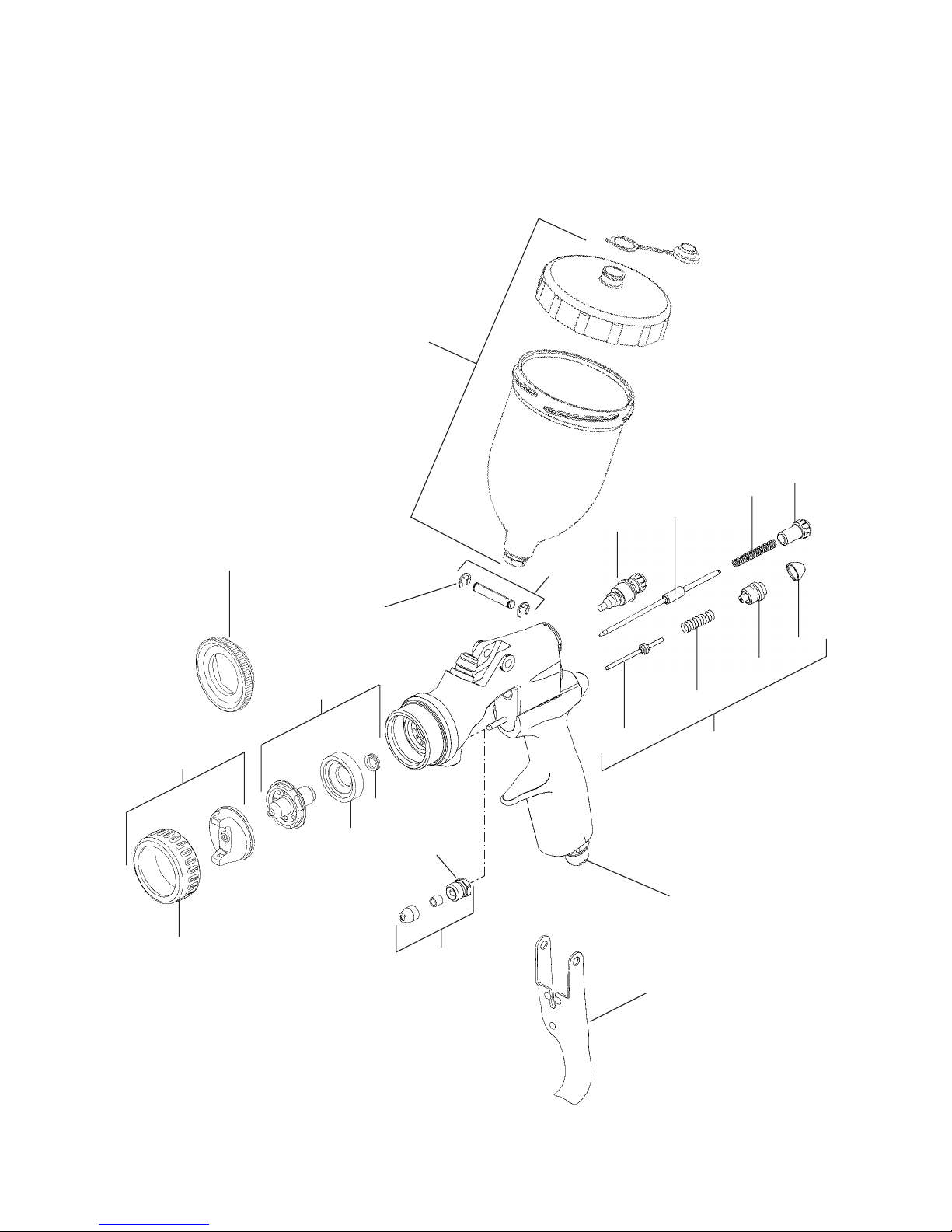
20
14
13
6
12
15
10
11
19
18
3
16
17
21
2
4
5
8
22
1
7
9
Page 3
Parts List For Gravity Feed Models
REF. Computer No. Part No. Description QTY.
1 519024 FLG-3-K2 Retaining Ring (Kit of 2) 1
2 see chart Air cap and Retaining Ring 1
3 see chart Fluid Tip Baffle and Seal 1
*4 519025 FLG-4-K5 Fluid Tip Seal
(Kit of 5) 1
5 Baffle 1
6 see chart Fluid Needle 1
*7 519130 FLG-410-K5 Needle Packing Kit
(Kit of 5) 1
*8 Packing Nut 1
9 519132 FLG-412 Trigger 1
*10 519029 FLG-8-K2 Trigger Stud Kit
(Kit of 2) 1
*11 Circlip 2
12 519123 FLG-403 Spreader Adjustment Valve 1
*13 Spring 1
*14 519124 FLG-404-K2 Needle Adjusting Screw
(Kit of 2) 1
*15 519031 FLG-11-K2 Tip Spanner 1
*16 Air Valve Stem and Seal 1
*17 Air Valve Spring 1
*18 Air Valve Cap Body 1
*19 Air Valve Cap 1
20 514302 FLG-502 Gravity Cup Assembly 1
21 519134 FLG-414 Air Valve Service Kit 1
22 519054 FLG-40 Air Inlet Adaptor 1
* Note these parts are included in the Spray gun repair kit.
519207 (FLG-460) Repair Kit: For all Gun and Cup outfits
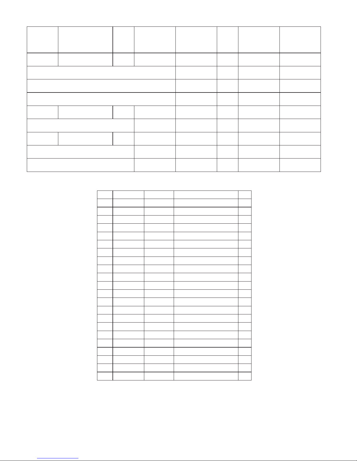
SPRAY GUN SPRAY GUN NO. ON REFERENCE #2 REFERENCE #3 FLUID REFERENCE #6 AIR CAP
COMPUTER MODEL AIR CAP AIR CAP FLUID TIP TIP FLUID NEEDLE TIP, NEEDLE
NUMBER NUMBER PART PART SIZE PART SET
NUMBER NUMBER (MM) NUMBER
512114 FLG-611-114 #1 519001(FLG-1-1K) 519014 (FLG-2-14K) 1.4(STD) 519114(FLG-401-14K) 519174(FLG-451-14)
OPTIONAL TIPS AND NEEDLES FOR FLG-611 519016(FLG-2-16K) 1.6 519116(FLG-401-16K) 519176(FLG-451-16)
AVAILABLE AS SERVICE PARTS ONLY 519018(FLG-2-18K) 1.8 519116(FLG-401-16K)
519022(FLG-2-22K) 2.2 519116(FLG-401-16K)
512212 FLG-611-212 #2 519002(FLG-1-2K) 519012(FLG-2-12K) 1.2(STD) 519112(FLG-401-12K) 519182(FLG-452-12)
AVAILABLE AS SERVICE PARTS ONLY 519014 (FLG-2-14K) 1.4 519114(FLG-401-14K) 519184(FLG-452-14)
512318 FLG-631-318 #3 519003(FLG-1-3K) 519018(FLG-2-18K) 1.8(STD) 519116(FLG-401-16K) 519196(FLG-453-18)
OPTIONAL TIPS AND NEEDLES FOR FLG-631 519016(FLG-2-16K) 1.6 519116(FLG-401-16K) 519194(FLG-453-16)
AVAILABLE AS SERVICE PARTS ONLY 519022(FLG-2-22K) 2.2 519116(FLG-401-16K) 519200(FLG-453-22)
Page 4

IMPORTANT: To ensure that this equipment reaches you in first class condition, protective coatings, rust inhibitors etc, have
been used. Flush all equipment through with a suitable solvent before use to remove these agents from the material passages.
1. Attach air supply hose to inlet connector from a filtered, regulated air supply.
2. Tighten cup lid securely onto cup body, snap lid vent cap closed before spraying.
Recommended air supply hose size: up to 10 metres long, 8 mm (
5
¼16") bore.
1. Strain the material through 60 or 90 mesh screen.
2. Adjust fluid needle adjustment screw to deliver the desired paint volume.
3. Adjust air pressure to provide a uniform dispersion of atomized paint throughout the pattern.
As a general rule: The No. 1 (conventional) air cap requires an air supply at gun inlet of approximately 45 psi
The No. 2 (conventional) air cap requires an air supply at the gun of approximately 40 psi
The No. 3 (HVLP) air cap requires a maximum of 23 psi gun inlet pressure, with 10 psi at the air cap
4. Keep air pressure as low as possible to minimize bounce back and overspray.
5. Excessive fluid flow will result in heavy center-spray patterns.
6. Inadequate flows may cause the pattern to split.
Cleaning
1. To clean air cap and fluid tip, brush exterior with a stiff bristle brush.
2. If any holes in the air cap are blocked use a toothpick or broom straw to remove the obstruction. Never use a steel wire
or hard implement this may scratch or blurr holes causing a distorted spray pattern.
3. To clean fluid passages, remove excess material in the cup, then flush with a suitable solvent.
4. Wipe gun exterior with a solvent - dampened cloth. Never completely immerse in solvent as this is detrimental to the
lubricants and packings.
Lubrication
Oil daily, the air valve stem where it enters the gun body and the needle (6) where it enters the screw (8). DeVilbiss spray gun
lube (SSL-10) is recommended for spray gun lubrication.
NOTE: The air and coating material connectors are not removable. They are fitted and sealed. Any attempt to remove them
will result in irreparable damage to the spray gun.
Nozzle (3) and Needle (6).
1. Remove the adjusting screw (14), spring (13) and needle (6).
2. Remove the retaining nut (1) and air cap (2).
3. Using the fluid tip tool (15) supplied, carefully unscrew the nozzle (3).
4. Remove the baffle plate (5).
5. Replace any worn or damaged parts.
6. Reassemble in the reverse order. Ensure that the baffle plate (5) is assembled in the correct direction.
Spreader Valve (12).
Remove valve assembly (12) and replace if necessary with a new assembly.
NOTE: When refitting the valve (12) always ensure that the adjusting knob is opened fully by turning counter-clockwise until
the stop is reached. Attempting to fit the valve in the closed position may result in damage to the unit.
Air Valve
1 Remove valve cap (19) using knife blade.
2 Remove valve cap body (18) using 6mm hex key.
3 Apply gun lube oil to new air valve stem and seal (16) and fit to gun
4 Replace new air valve spring (17) and valve cap body (18) and snap fit new valve cap (19) into place.
REPLACEMENT OF PARTS
PREVENTATIVE MAINTENANCE
OPERATION
INSTALLATION
Page 5

SAFETY WARNINGS
Solvents and coating materials can be highly flammable or combustible, especially when sprayed.
• Work stations must be provided with adequate ventilation/exhaust to prevent the build-up of flammable vapours.
• Smoking and naked flames must not be allowed in the spraying or mixing areas.
• Fire extinguishing equipment must be provided in the spraying and mixing areas.
Users must comply with all local and national codes of practice and insurance company requirements governing ventilation,
fire precautions, operation, maintenance and housekeeping of work stations.
HALOGENATED HYDROCARBON SOLVENTS - for example 1,1,1-Trichloroethane and Methylene Chloride can chemically
react with aluminium and galvanised or zinc coated parts and cause an explosion hazard. Read the label and data sheet of the
material you intend to spray.
DO NOT SPRAY MATERIALS CONTAINING THESE SOLVENTS EXCEPT WITH EQUIPMENT SPECIFICALLY
DESIGNATED BY THE MANUFACTURER AS BEING SUITABLE FOR SUCH USE.
STATIC ELECTRICITY - is generated by fluid moving through pipes and hoses. A static spark, capable of igniting certain
solvents and coating materials, could be produced by high fluid flow rates. To prevent the risk of fire or explosion, earth
continuity to the spray equipment and object being sprayed should be maintained.
TOXIC VAPOURS - when sprayed, certain materials may be poisonous, create irritation or otherwise be harmful to health.
Always read carefully all labels and safety/performance data for the material being sprayed and follow any recommendations.
IF IN DOUBT, CONSULT THE MATERIAL SUPPLIER.
• The use of respiratory protective equipment is recommended always when spraying. The type of respiratory protective
equipment used must be compatible with the material being sprayed and the level of concentration.
• Always wear eye protection when spraying or cleaning the equipment.
• Gloves must be worn for spraying or cleaning the equipment when certain coating materials and solvents are used.
Personnel should be given adequate training in the safe use and maintenance of this equipment. Training courses on all
aspects of the equipment are available. For details contact your local representative. The instructions and safety precautions
contained in this literature and the literature supplied with the coating material should be read and understood before the
equipment is used.
• All spray guns project particles at high velocity and must never be aimed at any part of the body.
• Never exceed the recommended safe working pressures for any of the equipment used.
• The fitting of non-recommended or non-original accessories or spare parts may create hazardous conditions.
• Before dismantling the equipment for cleaning or maintenance, all pressures, air and material, must be isolated and
released.
The disposal of non-metallic materials must be carried out in an approved manner. Burning may generate toxic fumes. The
removal of waste solvents and coating materials should be carried out by an authorised local waste disposal service.
The materials used in the construction of this equipment are (bearing in mind the warning on Halogenated Hydrocarbons)
solvent resistant enabling the equipment to be cleaned using gun washing machines. However, this equipment must not be left
inside the gun washing machine for prolonged periods of time after the automatic cleaning cycle has been completed. The
solvents used in the gun washing machine should be regularly checked to ensure that the equipment is not flushed through
with contaminated material. Follow the recommendations of the machine manufacturer.
The continuous A-weighted sound pressure level of this spray gun may exceed 85 dB(A) depending on the air cap/nozzle setup being used. Sound levels are measured using an impulse sound level meter and analyser, when the gun is being used in a
normal spraying application. Details of actual noise levels produced by the various air cap/nozzle set-ups are available on
request.
NOISE LEVELS
MISUSE
TRAINING
PERSONAL PROTECTIVE EQUIPMENT
FIRE AND EXPLOSION
Page 6

Gravity Feed Gun Hook: Order GFG-6 - A handy wall mounted bracket to hang up your gravity feed spray guns.
CONDITION CAUSE CORRECTION
A 1. No pressure at the gun. 1. Check air supply.
2. Screw (14) not properly adjusted. 2. Adjust.
3. Nozzle (3) blocked. 3. Clean.
B & C 1. Material build-up on air cap/nozzle (2, 3). 1. Clean air cap/nozzle.
D & E 1. Coating material flow or viscosity incorrect. 1. Adjust screw (14), or reduce
viscosity.
F 1. Insufficient material in cup 1. Fill cup.
2. Gun material passage blocked. 2. Clean.
3. Worn seal (7). 3. Replace.
4. Loose or damaged nozzle (3) 4. Tighten or replace.
5. Cup vent hole blocked. 5. Clean.
G 1. Seal (7) worn or seal screw (8) loose. 1. Check screw (8) and/or
1. replace seal (7).
H 1. Worn or dry seal (7). 1. Replace or lubricate.
2. Worn or damaged nozzle (3) or needle (6). 2. Replace.
SERVICE CHECKS
ACCESSORIES
NORMAL SPRAY PATTERN
A Will not spray
B
C
D
E
G
Fluid leakage from packing nut
Page 7

1 2 3
Keep
EZ LINERS
(1) Remove protective cap from piercing/assembly tool tip. Place drain bushing on tool.
(2) Install tool with bushing into the liner and pierce a hole in the bottom, centre of liner.
(3) Firmly push the bushing and liner into the drain hole in the paint cup bottom. Remove the tool with
a twisting motion.
(1) Place gun in gun holder and carefully open liner. Don’t pull liner up or bushing may be pulled out of drain hole.
(2) While holding funnel strainer, fill the liner to within 1" of the cup’s top. This will allow room to fold the liner into the paint cup.
(3) Starting at one end, slip the liner sealer end of the piercing tool over the liner’s zipper. Hold the liner at the same end and
slide the tool along the zipper. Make sure the tool overlaps the zipper.
NOTE: Do not use a hard instrument to clean air cap and fluid tip (nozzle) holes. They may be damaged resulting in a
distorted spray pattern.
(1) Disconnect the air hose and remove the paint cup lid.
(2) While holding disposable liner, point gun upwards and pull trigger until fluid passage is empty. (This allows paint in gun to
drain into the liner).
(3) While still pointing the gun upwards, carefully pull out liner. Keep drain bushing up to prevent leaking. To prevent paint from
being forced out of bushing, don’t squeeze the liner while handling it.
CLEANING
FILLING THE LINER
ASSEMBLY
Piercing/assembly
Liner
stretches
around
bushing to
make a leak-
proof seal
Hold liner
Drain
Piercing
Drain
1
2
3
Page 8

1724 INDIANWOOD CIRCLE
MAUMEE, OH 43537
CUSTOMER SERVICE
1-800-987-2278
Drain
Waste paint
Fluid tip
Straighten
brush
before
Hold tube brush
here when
installing into
456
798
(7) Pull trigger while flowing solvent.
(8) Remove air cap and brush air cap and fluid tip (nozzle) with clean solvent.
(9) Wipe the outside of gun with a solvent dampened cloth. Wipe gun dry and blow out the paint passages with air.
Spare Liner Kit : Order OMX-70-K48
ACCESSORIES
(4) Properly dispose of remaining paint in paint liner. Open zipper to allow for quicker draining of paint. Dispose of used liner
and bushing – DO NOT REUSE.
(5) Pour a small amount of clean paint solvent into paint cup.
(6) Clean drain hole and fluid tube with tube brush. Drain hole must be kept clean for proper sealing and easy removal of
drain bushing. Twirl brush in drain hole.
 Loading...