

Page 1
SERVICE MANUAL
❚ Repair Kit KK-5044
EGHV-531 HVLP SPRAY GUN
EN
(SPRAY PISTOL)
Important: Before using this equipment,
read all safety precautions and instructions. Keep for future use.
DESCRIPTION
The EGHV-531 HVLP spray gun is designed to be in compliance with rules
issued by South Coast Air Quality Management District (SCAQMD) and other air
quality authorities.
Note
All wetted surfaces are stainless steel and may be used with
materials formulated with chlorinated solvents. A list of materials used in the construction of
this equipment is available upon
request.
SPECIFICATIONS
Air Inlet 1/4" NPS (M)
Fluid Inlet 1/4" NPS (M)
Type Feed Suction or Pressure
Air Consumption 8.8 cfm Inlet Cap Press.
at 50 psi (249 liters/min. 50 psi 10 psi
at 3.5 bar) (3.5 bar) (.7 bar)
OPERATION
Prepare and strain material according
to the paint manufacturer's instructions.
Attach container to fluid inlet (24) and
tighten. Adjust incoming air pressure to
gun to approximately 50 psi (3.5 bar or
less). Use clean, dry air and adjust inlet
air pressure to obtain a maximum of 10 psi
(.7 bar) reading on GA-357 gauge (part of
Air Cap Test Kit, see Accessories).
EGHV can be used for pressure feed
application. Replace attached container
with fluid hose of proper size and construction to a remote supply. Adjust
fluid pressure to deliver the desired
amount of material that can be atomized at 10 psi (.7 bar) cap pressure
or less.
PREVENTIVE MAINTENANCE
To clean fluid passages, remove excess
material at source, then flush with a suitable solvent.
To clean air cap and fluid tip, brush with
a stiff bristle brush. If necessary, use a
broom straw or toothpick. Never use
a wire or hard instrument. This may
scratch or burr holes causing a distorted
spray pattern.
If performance problems develop, orifices could be plugged or contaminated
from the air supply or other sources.
These orifices are sized and tuned to
provide 10 psi (.7 bar) to air cap horn and
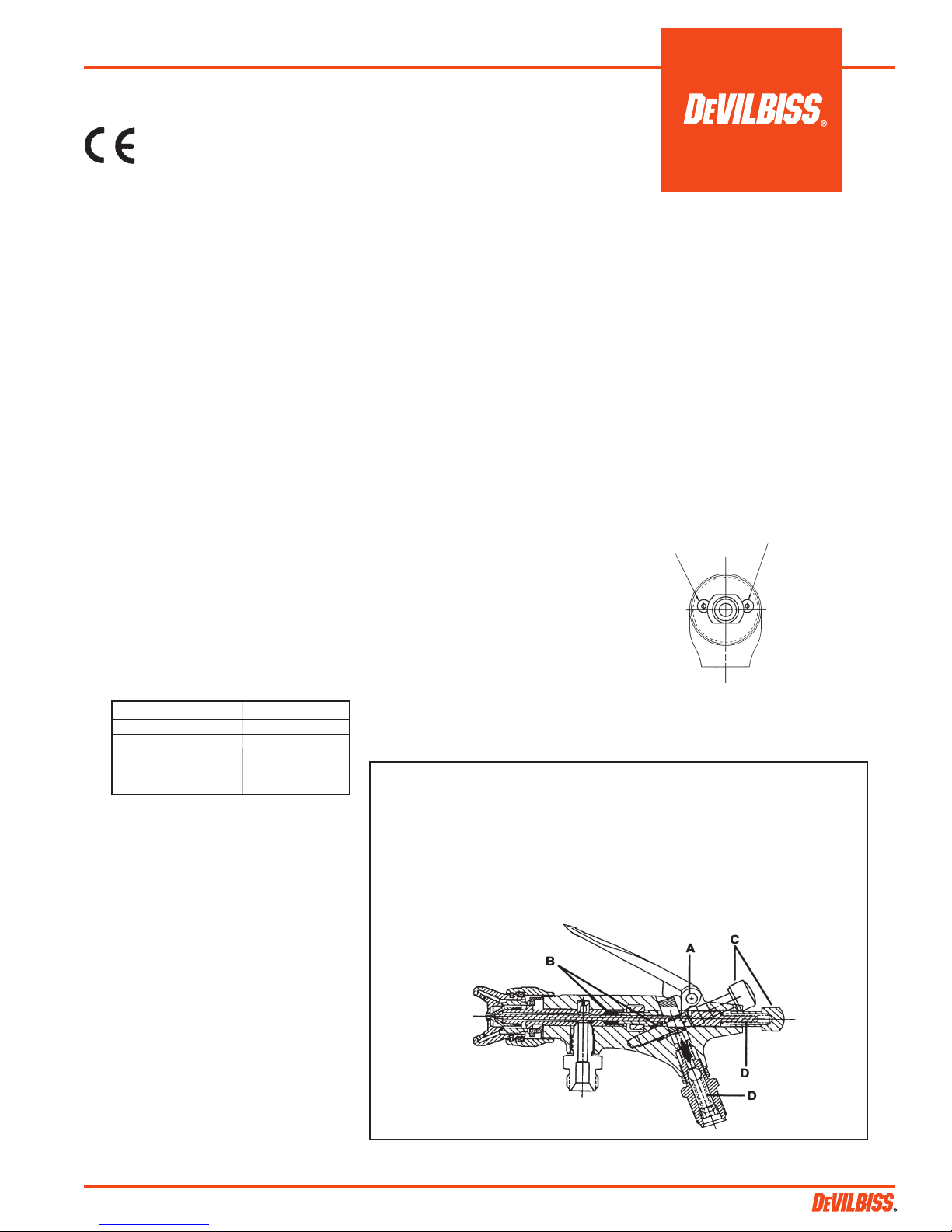
LUBRICATION
For best results, lubricate the points indicated in Figure 2 daily
using SSL-10 Gun Lube.
See Accessories.
A. Trigger points
B. Packings
C. Adjusting valves
D. Needle – Air valve springs (occasionally)
center air independently.
Procedure: Attach air cap test kit and
adjust pressure at inlet to 50 psi (3.5 bar)
with trigger depressed. Air cap test kit
gauge should read 10 psi + 0 -1 psi (.7 bar
+ 0 - .1 bar). If pressure varies more than
10%, clean orifices using the following
procedures. Remove tip (5), baffle (air
distributor) (6) and air valve (18) and
blow air back through the orifice to clear
blockage. Reassemble. See Figure 1.
Center Air
(Orifice)
Figure 1 (Facing front of gun with tip
removed)
Horn Air
(Orifice)
Note
Only use as much pressure as
required to atomize material.
SB-2-167-F (7/2014) 1 / 8
Figure 2
❚
Government NSN No. 4940-01-182-697 = KK-5044
Page 2
EN
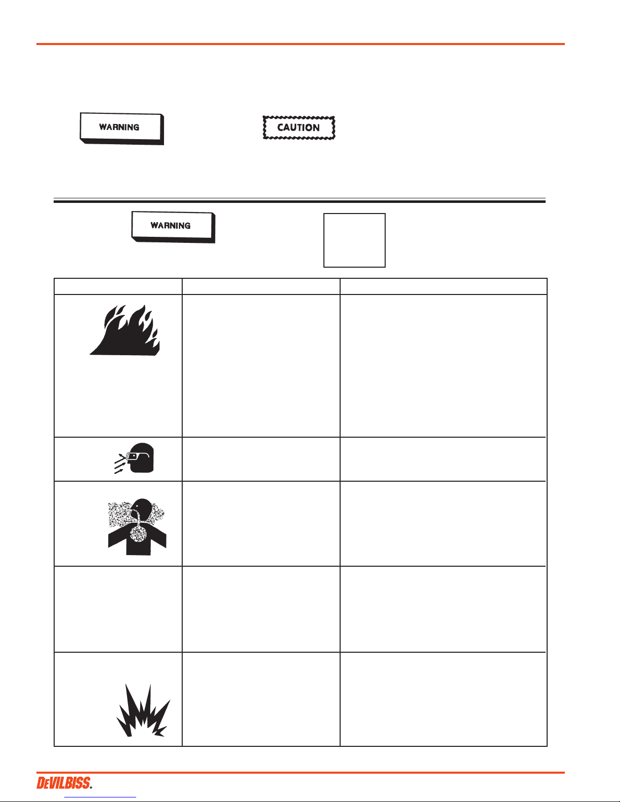
SAFETY PRECAUTIONS
This manual contains information that is important for you to know and understand. This information relates to USER SAFETY
and PREVENTING EQUIPMENT PROBLEMS. To help you recognize this information, we use the following symbols. Please pay
particular attention to these sections.
Note
Important safety information –
a hazard that may cause serious
injury or loss of life.
Important information that tells how
to prevent damage to equipment, or
how to avoid a situation that may
cause minor injury.
The following hazards may occur during the normal
use of this equipment. Please read the following chart.
CAUSE SAFEGUARDSHAZARD
Fire
Solvent Spray
Inhaling Toxic Substances
General Safety
Explosion Hazard –
Incompatible Materials
Solvents and coatings can be highly
flammable or combustible, especially
when sprayed.
During cleaning and flushing, solvents
can be forcefully expelled from fluid
and air passages. Some solvents can
cause eye injury.
Certain materials may be harmful if
inhaled or if there is contact with the
skin.
Improper operation or maintenance
of equipment.
Halogenated hydrocarbon solvents,
for example: methylene chloride
and 1,1,1, - Trichlorethylene, are
not chemically compatible with
the aluminum that might be used
in many system components. The
chemical reaction caused by these
solvents reacting with aluminum
can become violent and lead to an
equipment explosion.
Information that you should pay
special attention to.
CA PROP
65
1. Adequate exhaust must be provided to keep the
air free of accumulations of flammable vapors.
2. Smoking must never be allowed in the spray
area.
3. Fire extinguishing equipment must be present
in the spray area.
4. Static discharges must be prevented. Ground
(earth) all conductive objects in the spray
area, such as a cleaning solvent bucket, fire
extinguisher, etc.
5. When using solvents for cleaning:
• Those used for equipment flushing must have
• Those used for general cleaning must have flash
Wear eye protection
1. Follow the requirements of the Material
Safety Data Sheet supplied by your coating
manufacturer.
2. Adequate exhaust must be provided to keep the
air free of accumulations of toxic materials.
3. Use a mask or respirator whenever there is a
chance of inhaling sprayed materials. The mask
must be compatible with the material being
sprayed and its concentration.
Operators should be given adequate training in
the safe use and maintenance of the equipment
(in accordance with the requirements of NFPA-33,
Chapter 15 in U.S.). Users must comply with all
local and national codes of practice and insurance
company requirements governing ventilation,
fire precautions, operation, maintenance and
housekeeping (in the U.S., these are OSHA Sections
1910.94 and 1910.107 and NFPA-33).
This spray gun (spray pistol) can be used with
these solvents. However, aluminum is widely used
in other spray application equipment - such as
material pumps, regulators, valves, etc. Check all
other equipment items before use and make sure
they can also be used safely with these solvents.
Read the label or data sheet for the material you
intend to spray. If in doubt as to whether or not a
coating or cleaning material is compatible, contact
your material supplier.
PROP 65 WARNING
WARNING: This product contains chemicals
known to the State of California to cause
cancer and birth defects or other
reproductive harm.
a flash point equal to or higher than that of the
coating.
points above 100°F (37.8°C).
SB-2-167-F (7/2014)2 / 8
Page 3
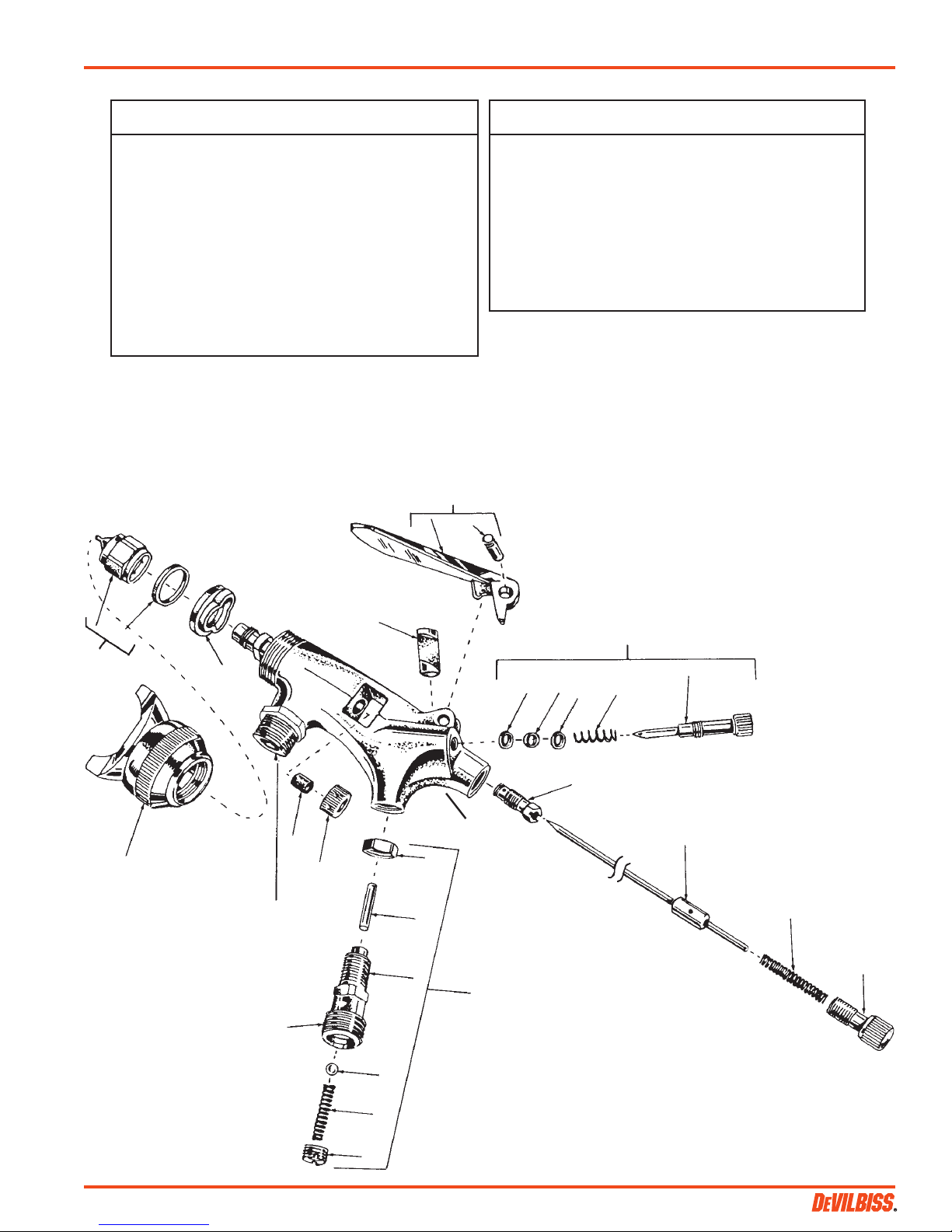
PARTS LIST
Ref. Replacement Individual
No. Part No. Description Parts Req.
1 EGA-4 Packing Nut 1
12 38273-136-K5 Needle Packing (Kit of 5) 1
3 EGHV-439-397HV Air Cap with Ring 1
4 EGA-7 Baffle (air distributor) 1
5 EGA-4000-E Tip, Needle & Gasket Assy. 1
6 EGA-59-K5 Gasket (Kit of 5) (Polyethylene) 1
7 EGA-443 Trigger & Stud Assy. 1
18 AG-3-1-K5 Trigger Bearing Stud (Kit of 5) 1
19 EGA-5-K6 Air Valve Plunger (Kit of 6) 1
10 EGA-454 Fan Adjustment Assy. - Horn 1
11 SSG-8205-K10 O-Ring (Kit of 10) 1
12 AG-26-K10 Washer (Kit of 10) 2
13 --- Spring 1
14 EGA-3 Packing Gland 1
WARRANTY
This product is covered by DeVilbiss' 1 Year Limited Warranty.
See SB-1-000 which is available upon request.
For Europe, this will not affect the purchasers statutory rights,
for example, under the U.K. Consumer Protection Act.
NOTE
7
EN
Ref. Replacement Individual
No. Part No. Description Parts Req.
15 --- Fluid Needle (included in Item 5) 1
16 AG-7-K5 Needle Spring (Kit of 5) 1
17 AG-16 Needle Adj. Screw 1
18 EGA-441 Air Valve Assy. 1
19 AG-46-K3 Lock Nut (Kit of 3) 1
20 EGA-9-K5 Stem (Kit of 5) 1
21 SST-3008-K5 Ball (Kit of 5) 1
22 --- Spring 1
23 GD-36-K5 Spring Retainer (Kit of 5) 1
24 EGHV-3 Fluid Adapter 1
25 EGHV-453 Gun Body Assy. 1
A necessary quantity of parts is included in Gun Repair Kit KK-5044.
Government NSN No. 4940-01-182-697 = KK-5044
Suffixes -K3, -K5, etc. designates kits of multiple parts.
Example: EGA-59-K5 is a kit of (5) seals.
8
9
6
10
5
4
12 11
12
13
14
25
15
2
3
1
24
19
20
16
Fluid Inlet
1/4" NPS(M)
17
Air Inlet
1/4" NPS(M)
SB-2-167-F (7/2014) 3 / 8
18
21
22
23
Page 4

EN
TROUBLESHOOTING
CONDITION CAUSE CORRECTION
Heavy top or bottom pattern Horn holes plugged. Clean. Ream with non-metallic point.
Obstruction on top or bottom of fluid tip. Clean.
Cap and/or tip seat dirty. Clean.
Heavy right or left side pattern Left or right side horn holes plugged. Clean. Ream with non-metallic point.
Dirt on left or right side of fluid tip. Clean.
Remedies for top-heavy, bottom-heavy, right-heavy and left-heavy patterns:
1) Determine if obstruction is on cap or fluid tip. Do this by making a test pattern. Then, rotate cap
one-half turn and spray another pattern. If defect is inverted, obstruction is on air cap. Clean air cap
as previously instructed.
2) If defect is not inverted, it is on fluid tip. Check for a fine burr on edge of fluid tip. Remove with
#600 wet or dry sand paper.
3) Check for dried material just inside opening. Remove by cleaning.
Heavy center pattern Material flow exceeds air cap’s capacity. Thin or lower fluid flow.
Atomizing pressure too low. Increase pressure.
Material too thick. Thin to proper consistency.
Split spray pattern Fluid adjusting knob turned in too far. Back out counterclockwise to achieve proper flow.
Atomization air pressure too high. Reduce air pressure.
Jerky or fluttering spray *Loose or damaged fluid tip/seat. Tighten or replace.
Material level too low. Refill.
Container tipped too far. Hold more upright.
Obstruction in fluid passage. Clean according to material supplier's
recommendations.
Loose or broken fluid tube or fluid inlet nipple. Tighten or replace.
Dry or loose needle packing nut. Lubricate or tighten.
Will not spray No air pressure at gun. Check air supply and air lines.
Needle adjusting screw not open enough. Open needle adjusting screw.
Excessive overspray Too much atomization air pressure. Reduce pressure.
(spray mist) Gun too far from work surface. Adjust to proper distance.
Improper stroking (arching, gun motion to fast). Move at moderate pace, parallel to work surface.
Gun out of adjustment. Adjust.
Fluid leaking from packing nut Packing nut loose. Tighten, do not bind needle.
Packing worn or dry. Replace or lubricate.
Fluid leaking or dripping from *Foreign matter in tip. Clean.
front of gun Packing nut too tight. Adjust.
Dry packing. Lubricate.
Fluid tip or needle worn or damaged. Replace tip & needle with lapped sets.
Needle spring deformed or broken. Replace.
Runs and sags Too much material flow. Adjust gun or reduce fluid pressure.
Material too thin. Mix properly or apply light coats.
Gun tilted at an angle. Hold gun at right angle to work and adapt to
proper gun technique.
Thin, sandy coarse finish. Gun too far from surface. Check distance. Normally 6-8" (152-203 mm).
Drying before it flows out Too much air pressure. Reduce air pressure and check spray pattern.
Improper thinner being used. Follow paint mfg's mixing instructions.
Thick, dimpled finish (orange Gun too close to surface. Check distance. Normally 6-8" (152-203 mm).
peel). Too much material Air pressure too low. Increase air pressure or reduce fluid pressure.
Improper thinner being used. Follow paint manufacturer’s mixing instructions.
Material not properly mixed. Follow paint manufacturer’s mixing instructions.
Surface rough, oily, dirty. Properly clean and prepare.
Excessive fog Too much, or too fast-drying thinner. Remix properly.
Too much atomization air pressure. Reduce pressure.
Unable to get round spray Fan adjustment screw not seating right. Clean or replace.
Air cap retaining ring (nut) loose. Tighten.
* Most common problem.
SB-2-167-F (7/2014)4 / 8
Page 5

ACCESSORIES
ING VALVE
Enables user to control
and reduce air usage
at the gun. Ideal for low
pressure spraying.
42884-214-K5 3/8"
42884-215-K10 5/8"
CLEANING BRUSHES
These brushes are helpful
in cleaning threads and
recesses of gun body.
Available in U.S. only.
Scrubs® Hand Cleaner Towels
29-3100
Scrubs® are a pre-moistened hand cleaner
towel for painters. No water is needed.
WR-103 WRENCH AIR CAP TEST KIT KK-5043
Contains all necessary tip, hose and
nut sizes used on or
with gun. Available
in U.S. only.
TGS CupsP-H-5516 AIR ADJUST-
TGS-503 polyethylene 8 ounce
(240 ml) suction
feed cup.
GUN LUBE, SSL-10
(2 oz. (60 ml) bottle)
Compatible with all
paint materials: contains no silicone or
petroleum distillates
to contaminate paint.
(397HV AIR CAP)
The purpose of
this test kit is
to measure air
cap atomizing air
pressure at the
air cap. Used
to confirm code
compliance and
as a daily quality
control measure.
EN
SB-2-167-F (7/2014) 5 / 8
Page 6

EN
NOTES
SB-2-167-F (7/2014)6 / 8
Page 7

NOTES
EN
SB-2-167-F (7/2014) 7 / 8
Page 8

EN
WARRANTY POLICY
DeVilbiss products are covered by Finishing Brands one year materials and workmanship limited warranty.
The use of any parts or accessories, from a source other than Finishing Brands, will void all warranties.
For specic warranty information please contact the closest Finishing Brands location listed below.
Finishing Brands reserves the right to modify equipment specications without
prior notice. DeVilbiss, Ransburg, BGK, and Binks are registered trademarks of
Finishing Brands. ©2014 Finishing Brands. All rights reserved.
DeVilbiss is part of Finishing Brands, a global leader in innovative spray nishing
technologies. For technical assistance or to locate an authorized distributor,
contact one of our international sales and customer support locations below.
USA/Canada
www.devilbiss.com
info@nishingbrands.com
Tel: 1-800-992-4657
Fax: 1-888-246-5732
United Kingdom
www.nishingbrands.eu
info@nishingbrands.eu
Tel: +44 (0)1202 571 111
Fax: +44 (0)1202 573 488
China
www.nishingbrands.com.cn
mkt@nishingbrands.com.cn
Tel: +8621-3373 0108
Fax: +8621-3373 0308
Mexico
www.nishingbrands.com.mx
sales@nishingbrands.com.mx
Tel: 011 52 55 5321 2300
Fax: 011 52 55 5310 4790
France
www.nishingbrands.eu
info@nishingbrands.eu
Tel: +33(0)475 75 27 00
Fax: +33(0)475 75 27 59
Japan
www.ransburg.co.jp
binks-devilbiss@ransburg.co.jp
Tel: 081 45 785 6421
Fax: 081 45 785 6517
Brazil
www.devilbiss.com.br
sales@devilbiss.com.br
Tel: +55 11 5641 2776
Fax: 55 11 5641 1256
Germany
www.nishingbrands.eu
info@nishingbrands.eu
Tel: +49 (0) 6074 403 1
Fax: +49 (0) 6074 403 281
Australia
www.nishingbrands.com.au
sales@nishingbrands.com.au
Tel: +61 (0) 2 8525 7555
Fax: +61 (0) 2 8525 7500
SB-2-167-F (7/2014)8 / 8
 Loading...