

Page 1
SB-E-8-305
OPERATION MANUAL
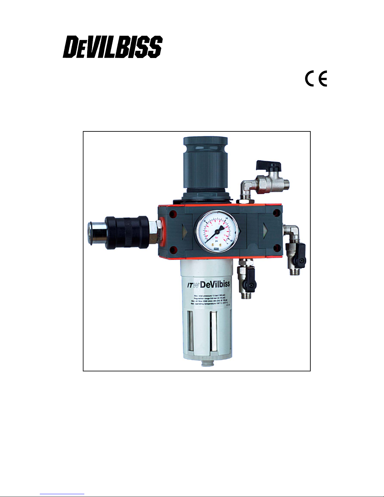
DVFR-1 Air Filter Regulator
ISS.05
Page 2
2
© 2003 ITW Finishing Systems and Products
EE
Specifications
Air supply connection 1/2” BSP female.
Air outlet connections 1/4” BSP male.
Gauge port 1/8” BSP female.
Size width 175 mm
height 280 mm
Weight 2.5 kg
Maximum:
air flow 3550 l/min
air supply pressure 13 bar
regulated air pressure 0-8 bar
operating temperature 100° C
Filter aperture size 5 micron
Typical pressure drop 0.75 bar
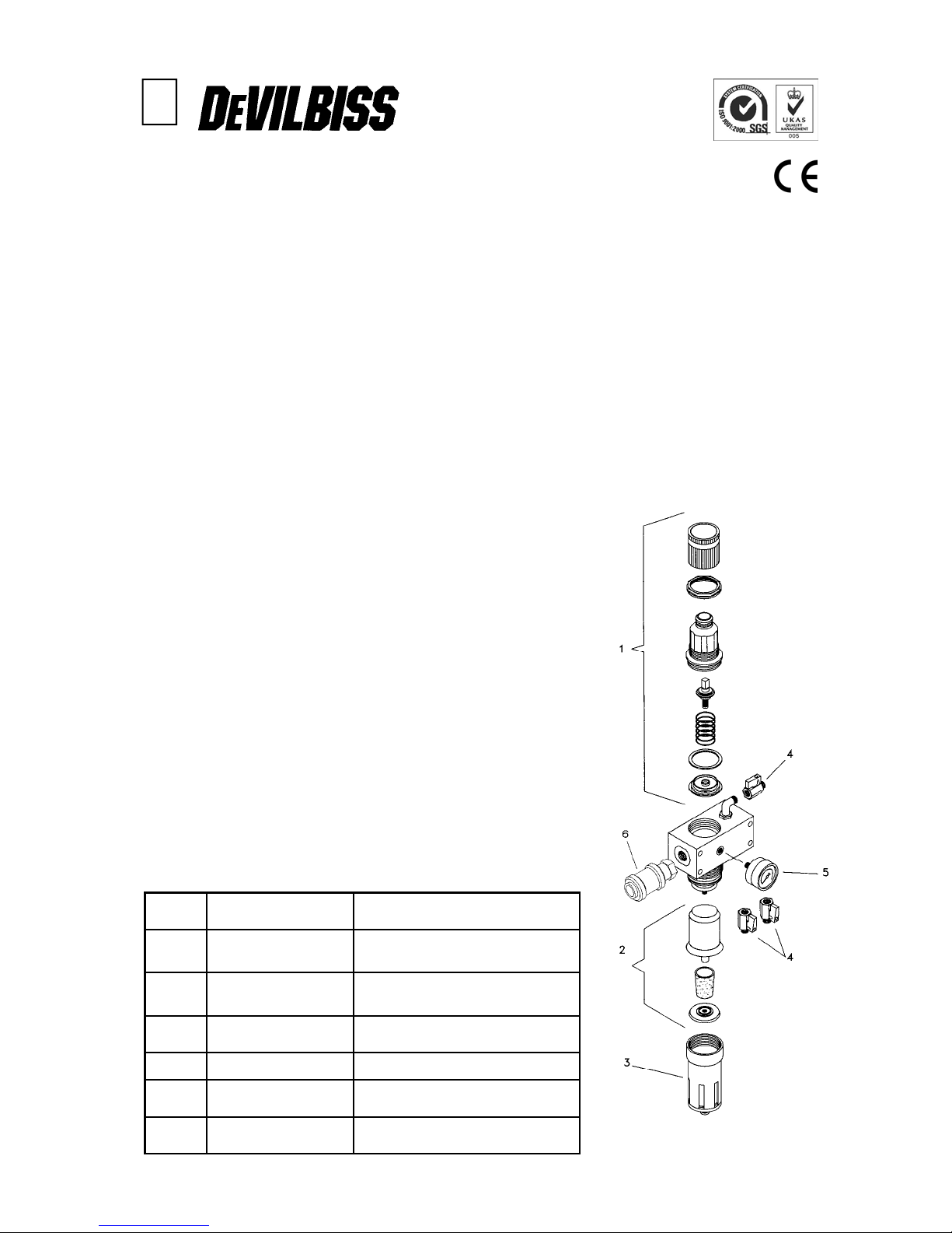
Parts List
Operation Manual
DVFR-1 Air Filter Regulator
Important
Read and follow all instructions and Safety Precautions before using this equipment
Description
A compact Air Filter Regulator suitable for 1 or 2 operators, designed to remove entrained dirt, liquid oil and
water from flowing compressed air, and to regulate the air pressure to enable air using devices to be
operated.
Regulator is a self relieving design that senses over-pressure at the regulated outlets and vents excess
pressure to atmosphere. The rolling diaphragm improves pressure sensitivity adjusting the valve for
fluctuating airflows and pressures.
Model
Order No. DVFR-1 Filter regulator unit. Complete with air pressure gauge and mounting bracket.
Ref No Part No Description
1 DV-9450806 Upper Cover Assembly
including diaphragm
2 DV-9451705 Replacement Filter Element
(5 microns)
3 DV-9453301-MET Metal Filter Bowl with drain valve
4 SER-3414-MF Ball Valve 1/4 inch BSP (m) & (F)
5 GA-319 Pressure Gauge 0-160 psi
6 DV-8000035 Isolation Valve
Page 3

3
© 2003 ITW Finishing Systems and Products
SAFETY WARNINGS
EE
Misuse
• Never exceed the recommended safe working pressure/temperature for any of the equipment used.
• Do not use paint solvents to clean the unit or filter element.
• The fitting of non- recommended or non- original accessories or spare parts may create hazardous
conditions.
• Do not install the unit above electrical or any other equipment that will be damaged by discharged
condensate.
• Before dismantling the equipment for cleaning or maintenance, all air pressures must be isolated and
released.
• When assembling an air pressure gauge to the unit DO NOT use a spanner, always tighten by hand.
• The disposal of non-metallic materials must be carried out in an approved manner. Burning may
generate toxic fumes.
Installation / operation
1. Always install the unit so that the air flows in the direction indicated by the arrows on the body.
2. Install the unit as near as possible to the point of use.
3. Always depressurise the unit before periodic maintenance and installation.
4. Ensure the earth lead is connected to an earth point and verify continuity from each ball valve (item 4)
to another known earth point, a resistance of less than 1k ohm should be achieved for dissipation of
electrostatic charge.
5. An isolation valve is fitted (6) to the inlet of the unit to allow condensate to be drained and for ease of
maintenance. Slide to the right towards the regulator to open. Slide to the left to close.
6. When reducing the pressure, always turn the regulator below the required pressure and adjust
upwards. When assembling the pressure gauge to the unit always tighten by hand. DO NOT USE A
SPANNER. (Fig 6).
7. To lock the regulator press the adjusting knob down . To release the lock lift the knob up.
8. The condensate drain valve on the bottom of the filter can be used semi-automatically or
manually.
a) With the push button in the central position the valve is semi-automatic (i.e. when the filter bowl is
depressurised the valve will open allowing the condensate to drain from the bowl). When the bowl is
pressurised the drain valve will automatically close.
b) If necessary, it is possible to drain the condensate while the filter bowl is pressurised. To do this,
the simple operation of pushing the valve up will open the drain and release the condensate.
c) By rotating the button clockwise, the valve becomes locked closed. Drainage is impossible in this
position and can only occur when the button is returned to the central position.
Note: To unscrew the bowl from the unit , use a compass key (pin spanner) with 2 mm diameter
pins.
Maintenance
Cleaning: The filter element can be removed and cleaned, by removing condensate bowl and unscrewing tie
rod.
It is recommended that filter/coalescer/activated carbon elements are replaced periodically i.e. when a drop
in pressure is noticeable through the unit or every 6 months.
Ensure earthing of the unit is not affected by maintenance activities , see installation above.
Page 4

4
© 2003 ITW Finishing Systems and Products
ITW Finishing Systems and Products
Ringwood Road,
Bournemouth,
BH11 9LH,
England.
Tel. No. (01202) 571111
Telefax No. (01202) 581940,
Website address http://www.itweuropeanfinishing.com
ITW Oberflächentechnik GmbH & Co. KG
Justus-von-Liebig-Straße 31
63128 Dietzenbach
Tel (060 74) 403-1
Telefax: (060 74) 403300
Website address http://www.itw-finishing.de
ITW Surfaces et Finitions
163-171 avenue des Auréats B.P. 1453
26014 VALENCE CEDEX FRANCE
Tél. (33) 475-75-27-00
Télex 345 719F DVILBIS
Téléfax: (33) 475-75-27-99
ITW Finishing Systems and Products is a Division of ITW Ltd.
Reg. Office:
Admiral House,
St Leonard’s Road,
Windsor,
Berkshire,
SL4 3BL,
UK
Registered in England: No 559693 Vat No 619 5461 24
June 08
 Loading...