

DeVilbiss DV6WM Instruction Manual
DV6WM DeVilbiss Wireless Modem Instruction Guide
C US
EN
Made in USA of US and Imported Parts.
Guía de instrucciones del Módem inalámbrico DV6WM de DeVilbiss
ES
Hecho en EE. UU. con piezas nacionales e importadas.
Guide d’utilisation du Modem sans fil DV6WM DeVilbiss
FR
Fabriqué aux États-Unis avec des pièces des États-Unis et des pièces importées.
ENGlISH ................................................................... EN-2
IP21
ESPAÑOL ................................................................ ES-14
FRANÇAIS ............................................................... FR-26
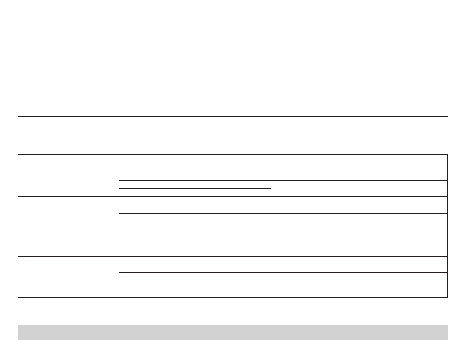
TABLE OF CONTENTS
Intended Use ........................................................................... EN - 2
Contraindications ..................................................................... EN - 2
Symbols ................................................................................... EN - 2
Important Safeguards .............................................................. EN - 3
Do not use the device or accessories in an environment with
electromagnetic equipment such as CT scanners, Diathermy, RFID and
electromagnetic security systems (metal detectors) as it may cause
unacceptable risk to the patient or damage to the device. Some
electromagnetic sources may not be apparent, if you notice any
unexplained changes in the performance of this device, if it is making
unusual or harsh sounds, disconnect the power cord and discontinue
use. Contact your home care provider.
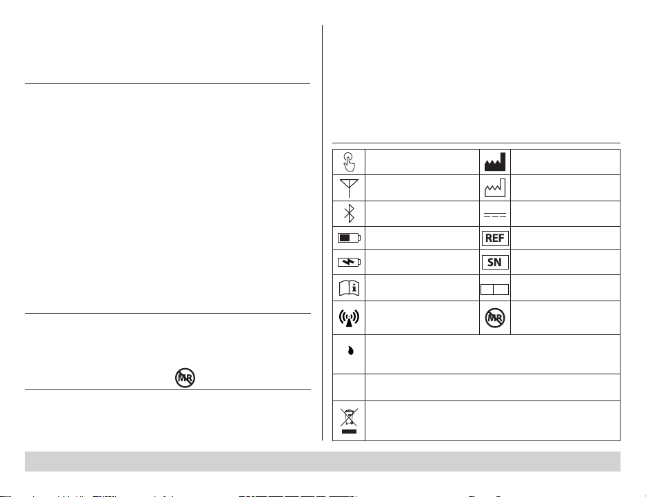
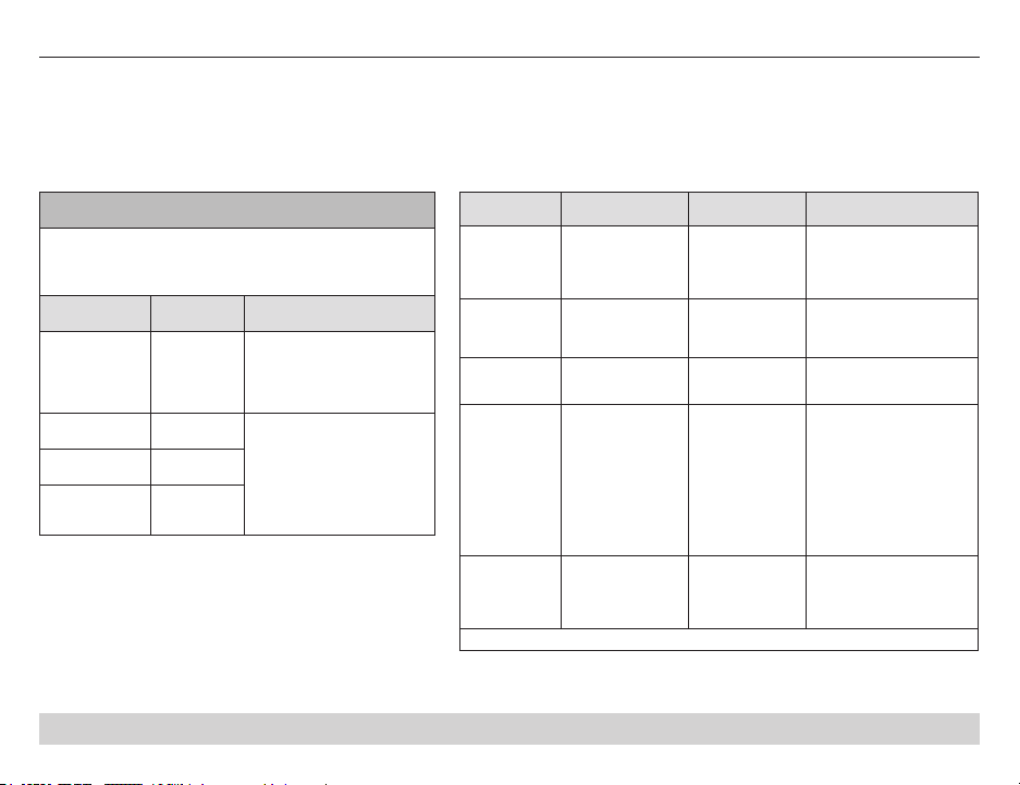
SYMBOLS
Cautions / Warnings ............................................................ EN - 3
Package Contents ................................................................... EN - 4
Test Call Button Manufacturer
Important Parts ........................................................................ EN - 4
Set Up & Operation - DV6x Series CPAP ............................... EN - 5
Initial Set Up of Your Wireless Modem ............................... EN - 5
Operating your Wireless Modem ........................................ EN - 6
Charging the Modem Battery .................................................. EN - 7
Cleaning / Maintenance / Disposal .......................................... EN - 8
Specifications ............................................................................. EN - 9
Troubleshooting .......................................................................... EN - 10
EMC Information ........................................................................ EN - 11
INTENDED USE
The DeVilbiss Healthcare DV6WM Wireless Modem is intended for
use as an accessory to a DV6x Series CPAP and DV5x Series CPAP
with SmartLink II Bluetooth module for patients in a home or
healthcare environment.
CONTRAINDICATIONS MR Unsafe
Do not bring the device or accessories into a Magnetic Resonance
(MR) environment as it may cause unacceptable risk to the patient or
damage to the device or MR medical devices. The device and
accessories have not been evaluated for safety in an MR environment.
EN - 2 SE-DV6WM-1
Cell Phone Status LED Date of Manufacture
Bluetooth Status LED DC voltage symbol
Battery Status LED Model number
Battery Charge Connector Serial Number
Refer to Operating
Instructions
EC REP
European Representative
MR Unsafe – Unsafe for
Radio transmitter
Magnetic Resonance
Environment
Ingress Protection - Protected against nger access to
hazardous parts; protected against vertically falling water
drops
Rx
CAUTION - USA Federal law restricts this device to sale by or
on the order of physician
Only
This device contains electrical and/or electronic equipment
that must be recycled per EU Directive 2012/19/EU- Waste
Electrical and Electronic Equipment (WEEE)
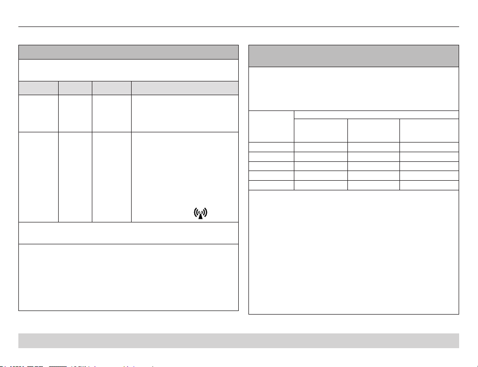
IMPORTANT SAFEGUARDS
READ ALL INSTRUCTIONS BEFORE
USING THIS DEVICE.
SAVE THESE INSTRUCTIONS.
(per IEC 60601-1-2:2007 Section 5.2.2.1 b)
WARNING: The use of ACCESSORIES, transducers and cables
other than those specied, with the exception of transducers and
cables sold by DeVilbiss Healthcare as replacement parts for
internal components, may result in increased EMISSIONS or
decreased IMMUNITY of the ME EQUIPMENT or ME SYSTEM.
(per IEC 60601-1-2:2007 Section 5.2.2.1 d)
WARNING: The DeVilbiss DV6WM Wireless Modem should not be
used adjacent to or stacked with other equipment and that if
adjacent or stacked use is necessary, the DeVilbiss DV6WM
Wireless Modem should be observed to verify normal operation
in the conguration in which it will be used.
(per IEC 60601-1-2:2007 Section 5.2.2.5)
WARNING: The DeVilbiss DV6WM Wireless Modem may be
interfered with by other equipment, even if that other equipment
complies with CISPR EMISSION requirements.
RF receiver frequency band BT 2.402 GHz ~ 2.480 GHz
RF receiver bandwidth BT 2.402 GHz ~ 2.480 GHz
RF receiver frequency band GSM 824.2 MHz ~ 1907.6 MHz
RF receiver bandwidth GSM 824.2 MHz ~ 1907.6 MHz
(per IEC 60601-1-2:2007 Section 5.2.2.5)
RF transmit frequency band BT 2.402 GHz ~ 2.480 GHz
Modulation BT GFSK, 8DPSK
Effective Radiated Power BT < -10 dBm (100 mW)
RF transmit frequency band GSM 824.2 MHz ~ 1907.6 MHz
Modulation GSM 8-PSK, WCDMA
Effective Radiated Power GSM < +33 dBm(2,000 mW)
CAUTIONS / WARNINGS
• Refer to International Standard IEC 60601-1 Ed 3.0 Amendment
1 for safety requirements applicable to Medical Electrical
Systems.
• Electric shock hazard-Do not attempt to open or remove the
Wireless Modem or charger cabinet; there are no userserviceable components inside. If service is required, contact
your equipment provider for instructions on obtaining service.
Opening or attempting to service your device will void the
warranty.
• Do not perform service or maintenance while the Wireless
Modem is in use.
• Wireless Modem contains Lithium Polymer (LiPO) battery. Do
not dispose of in household waste.
• The replacement of lithium batteries by inadequately trained
personnel could result in a HAZARD. There are no user
serviceable parts inside the DV6WM Wireless Modem, the
modem should only be serviced by a qualied DeVilbiss
provider.
• If the Wireless Modem begins to perform in an unusual
manner or a way not described in this guide, do not attach the
Wireless Modem to a charger or any other equipment. Contact
your equipment provider and report the unusual performance.
• If Wireless Modem is exposed to extreme temperatures or
humidity during storage, allow the device to sit at room
temperature for 2 hours before operating or charging.
• Do not connect the DV6WM Wireless Modem to equipment not
described in these instructions. Connecting the modem to
other equipment or accessories may result in malfunction or
damage to the DV6WM Wireless Modem.
• Do not modify the DV6WM Wireless Modem or accessories
this may result in malfunction or damage to the DV6WM
Wireless Modem.
EN - 3SE-DV6WM-1
CAUTIONS / WARNINGS
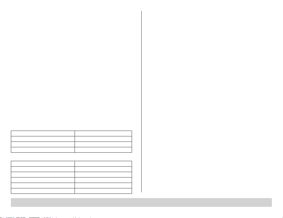
PACKAGE CONTENTS
• Use only chargers and charging
cables provided by DeVilbiss for use
with the DV6WM Wireless Modem.
Use of other chargers or charging
cables may result in malfunction or
damage to the DV6WM Wireless
Modem.
DV6WM Wireless
Modem
USB Wall
Charger
Instruction Guide
For storage and handling – The
following conditions may cause a re
hazard by causing a failure of the
internal rechargeable battery:
• Never attempt to charge a Wireless
Modem with physical damage.
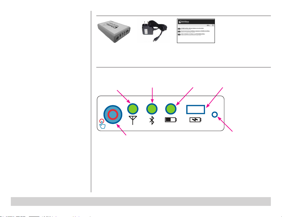
IMPORTANT PARTS
Wireless Modem – Control Panel
Cell Phone
(link to server)
Bluetooth (link to CPAP)
Battery
Battery charging
connector (USB)
• If Wireless Modem temperature
exceeds 50˚C (122˚F), terminate
charging.
• Do not heat or throw Wireless
Modem into a re.
• Do not use or store Wireless Modem
close to re or inside the car where
temperature may be over 60˚C.
• Do not immerse the Wireless Modem
in water.
Test Call button
Press to confirm LEDs illuminate
DV6WM-122 Rev. C
Reset (do not press unless
instructed by your provider)
Normal Operation
The battery LED ashes when battery is low, otherwise all LEDs remain OFF except during call
sequence. During the call, the battery LED illuminates solid and either Bluetooth or Cell LEDs are
also active. You may not see this happen.
Call frequency has been preset by your provider.
NOTE: When battery LED ashes, refer to Charging the Modem Battery.
NOTE: To check operation at any time, press the test call button and conrm LEDs illuminate.
EN - 4 SE-DV6WM-1
SET UP & OPERATION - DV6x Series CPAP
PRESS
PRESS
PRESS
Initial Set Up of Your Wireless Modem
NOTE: Fully charge battery before beginning set up. Refer to Charging
the Modem Battery.
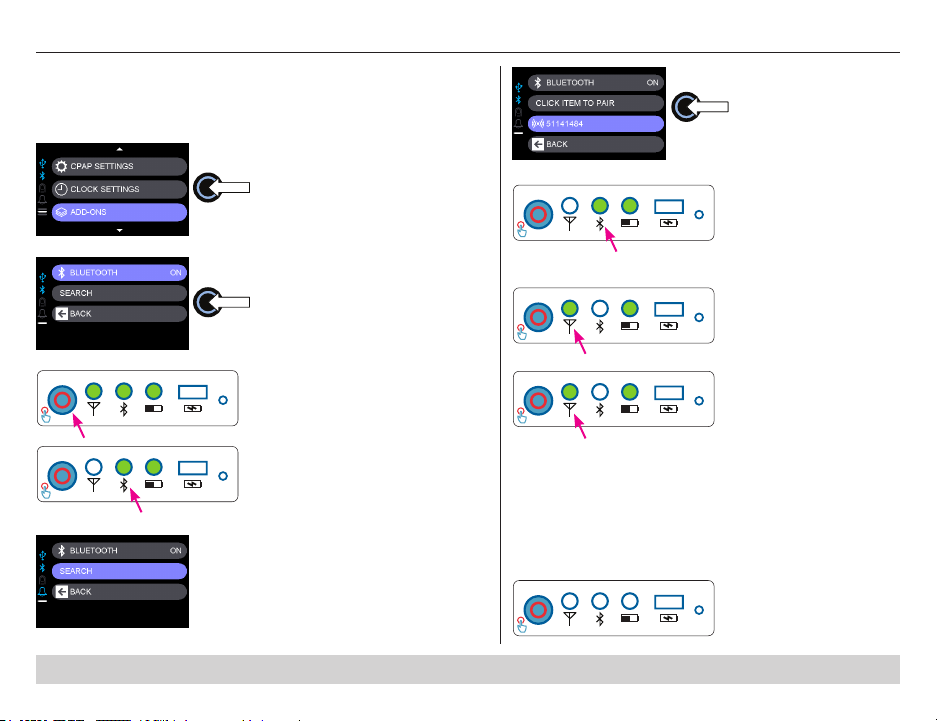
1. Check DV6X CPAP to ensure
Bluetooth is ON
a. Navigate to ADD-ONS
b. Select Bluetooth
c. Press to toggle from OFF to ON
if necessary
2. Press Test Call button on Wireless
Modem
a. All LEDS will illuminate for
approximately 1 second, then
turn OFF
b. Battery LED shows battery
status
c. Bluetooth LED will begin ashing
DV6WM 122 Rev C
slowly while searching for CPAP
3. Pair with DV6x Series CPAP
a. Modem bluetooth LED will begin
DV6WM 122 Rev C
ashing fast when ready to pair
with CPAP (approximately 30
seconds for fast ash to begin)
b. The wireless modem serial
number will appear on the list
when the CPAP nds it
NOTE: Wait until Modem appears
in list, this may take 30 seconds.
DV6WM 122 Rev C
DV6WM 122 Rev C
DV6WM 122 Rev C
DV6WM 122 Rev C
c. At Click Item to Pair
screen, select
Wireless Modem
serial number and
press, the menu will
show “Pairing…” then
“Success”
d. The Bluetooth LED on
the Wireless Modem
will stop ashing and
stay ON while reading
data from the CPAP
4. The Cell Phone LED on
the modem will ash and
then turn solid for a few
minutes
5. Find a location where Cell
Phone LED is ON (not
ashing) and place the
modem where it will not
be disturbed
NOTE: Bluetooth and Cell
Phone LEDs will normally be
OFF; they will be active only
when modem is talking to
CPAP or to the server; you
may not see this happen.
Leave modem alone.
6. After call sequence is
nished, all LEDs will turn
OFF
EN - 5SE-DV6WM-1
SET UP & OPERATION - DV6x Series CPAP
PRESS
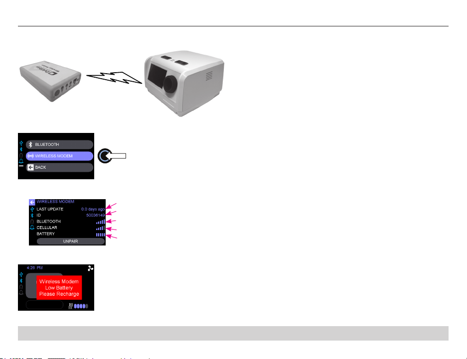
Operating your Wireless Modem with Your DV6x Series CPAP
The DeVilbiss Wireless Modem operates without interaction as long as the battery level is good.
To see modem info, select Wireless Modem in the ADD
ONS menu on the DV6x CPAP and press.
Info shown on DV6x CPAP display for Wireless Modem
Days since last upload to server
Wireless Modem ID
Bluetooth Signal
Cell Phone Signal
Battery Level
NOTE: The DV6x Series CPAP will report low modem battery.
When you see this message, refer to Charging the Modem
Battery. The low battery message appears when blower is turned
ON.
EN - 6 SE-DV6WM-1
CHARGING THE MODEM BATTERY
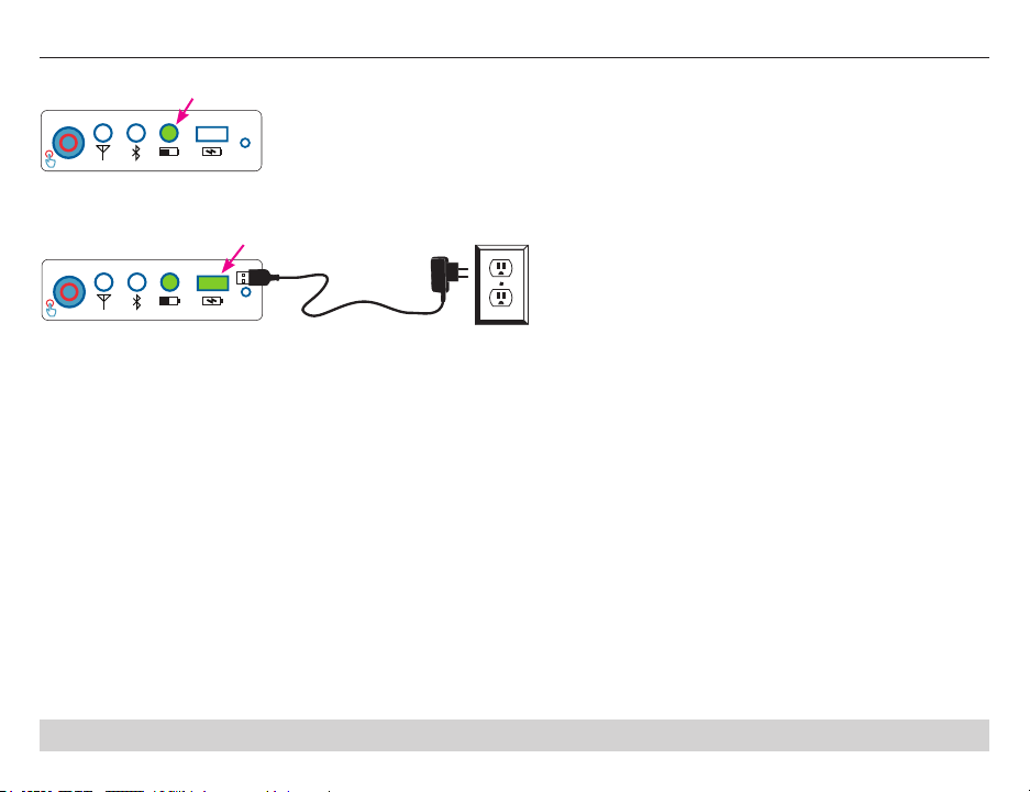
flashes when low
When the battery level gets low,
the Battery LED on the modem
DV6WM 122 Rev C
will ash. Refer to Charging
the Modem Battery.
USB Wall
DV6WM 122 Rev C
Charger
Wall Outlet
The Battery LED will ash 3 times in 1 second every 3 seconds when the battery level gets low. If the Battery LED is ashing, plug the provided
USB Wall Charger into the modem and the wall outlet.
Battery LED on the modem will:
• Flash slowly when battery is charging
• Stay on steady when battery is fully charged and connected to the power source
NOTE: If desired, the modem can be plugged in at all times.
The DV6WM Wireless modem operates normally while the battery is charging. The modem may be left plugged into the charger for an extended
period of time.
Typical operation time of theDV6WM Wireless Modem on a full battery charge is 90 days.
EN - 7SE-DV6WM-1

CLEANING INSTRUCTIONS
1. Clean modem once per month. Unplug Wireless Modem from
charger and wipe outside surface with a damp cloth.
2. Store Wireless Modem in a dry place at room temperature when
not in use.
Multi-Patient Use
If the device is to be used by multiple persons in a healthcare
environment or device rental program, the outside of the device must
be cleaned and disinfected between patients.
Cleaning for Multi-Patient Use
WARNING
If you are using the device on multiple patients, complete the
following steps to clean the outside of the device only before
each new user.
1. Unplug the device before cleaning.
2. Use a cloth with a solution of mild detergent (e.g. Dawn
dishwashing liquid) and water to remove debris if necessary.
3. Use a cloth with a 1:10 dilution of 5.25%–6.15% sodium
hypochlorite (i.e., household bleach) to clean the exterior of the
device.
4. Ensure that the device is completely dry before plugging in the
power cord.
MAINTENANCE
WARNING
Electric shock hazard-Do not attempt to open or remove the
Wireless Modem or charger cabinet; there are no userserviceable components inside. If service is required, contact
your equipment provider for instructions on obtaining service.
Opening or attempting to service your device will void the
warranty.
The Wireless Modem and accessories require no maintenance
through the expected service life.
EXPECTED SERVICE LIFE
DV6WM Wireless Modem ............................................5 years
AC to DC USB wall charger ........................................ 2 years
DISPOSAL
CAUTION: Wireless Modem contains Lithium Polymer (LiPO) battery.
Do not dispose of in household waste.
Wireless Modem and charger contain electronic waste, contact local
authorities to determine proper method of disposal of electronic parts,
plastic parts and LiPO battery.
NETWORK/DATA COUPLING
• Connection of the DV6WM Wireless Modem to a network/data
coupling that includes other equipment could result in previously
unidentied risks to patients and operators, and the responsible
organization should identify, analyze, and control such risks;
• Subsequent changes to network/data coupling may introduce new
risks, requiring new analysis;
Changes to network/data coupling include:
• Changes in network/data coupling conguration
• Connection of additional items to network/data coupling
• Disconnecting items from network/data coupling
• Update of equipment connected to network/data coupling
• Upgrade of equipment connected to network/data coupling
EN - 8 SE-DV6WM-1
SPECIFICATIONS
Size ........................................................................................................................................................... 4.4”H x 3”W x 1”D (11.2cm x 7.6cm x 2.5cm)
Weight ................................................................................................................................................................................................ 0.35 lbs. (158.8 g)
Electrical Requirements AC ....................................................... 100 – 240 VAC, 50/60 Hz, 120 mA (Specified external AC to DC USB charger input)
Electrical Requirements DC ................................................................. 4.74 to 5.25 VDC, 500 mA (Specified external AC to DC USB charger output)
Maximum Power Consumption ................................................................................................................................3 watts from AC to DC USB charger
Operating Temperature Range ..............................................................................................................................................41˚F to 104˚F (5˚C to 40˚C)
Operating Humidity Range ........................................................................................................................................... 15% to 95% RH non-condensing
Operating Atmospheric Conditions .....................................................................................700 hPa to 1060 hPa (~9800 ft to ~ 1400ft below sea level)
Storage & Transportation Temperature Range ............................................................................................................. 13˚F to +158˚F (-25˚C to +70˚C)
Storage & Transportation Humidity Range ....................................................................................................................0% to 95% RH non-condensing
Technical Specs (per IEC 60601-1-2:2007 Section 5.2.2.1 a)
Cables compatible with the DeVilbiss DV6WM Wireless Modem ........................................ USB to Micro B USB cable, max cable length = 6 ft (1.8m)
USB Wall Charger ........................................................................................................................................................ Input 100 - 240 VAC, 47 – 63 Hz
Output 5 VDC, 3 Watt max
Output connector USB Micro B
Max cable length = 6 ft (1.8 m)
Wireless Specications: Bluetooth
This medical device contains two radio transmitters, Bluetooth and 3G cellular. The Bluetooth radio integrated into this device is active when the
Bluetooth Status LED ( ) on the control panel is illuminated. Bluetooth is used to connect wirelessly to your medical device. The 3G cellular radio
integrated into this device is active when the Cell Phone Status LED ( ) on the control panel is illuminated. The 3G cellular radio is used to send
data read from your medical device to a remote data server. If you notice any unexplained changes in the performance of the wireless function or
your device, turn the Bluetooth radio off to see if that is the cause. You may experience issues with wireless technology such as delays in displayed
or stored data, artifact or gaps in the data due to information lost during wireless transfer.
Radio Technology ................................................................................................................................................. Bluetooth 2.1 +EDR and Bluetooth 4.0
Bluetooth Power Class ..................................................................................................................................................................................................1.5
Network Topology ......................................................................................................................................................................................... Point to Point
Bluetooth Profile Supported ........................................................................................................................................................................................SPP
Effective Range ............................................................................................................................................................................50 meters (line of sight)
Effective Radiated Power ..................................................................................................................................................................... 10 dBm (100 mW)
Radio frequency band (Tx and Rx) ............................................................................................................................................. 2.402 GHz ~ 2.480 GHz
Minimum Separation Distance (to other RF transmitters) .............................................................................................................................1 cm (0.4 in.)
EN - 9SE-DV6WM-1
Wireless Specifications 3G Cellular:
Radio Technology ........................................................................................................................................................................................... 3G Cellular
Network Topology ....................................................................................................................................................................................... Point to Point
Effective Radiated Power .................................................................................................................................................................... max 33 dBM (2 W)
Radio frequency band (Tx and Rx) ...........................................................................................................................................824.2 MHz ~ 1907.6 MHz
Minimum Separation Distance (to other RF transmitters) .............................................................................................................................1 cm (0.4 in.)
Quality Of Service Required ................................................................................................................................................................1 Bar (> -124 dBM)
Security Requirements:
Authentication ............................................................................................................................. Enforced on all data channels (outgoing and incoming)
Encryption ..............................................................................................................................................................................................Base 64 encoding
TROUBLESHOOTING
CAUTION: If the Wireless Modem begins to perform in an unusual manner or a way not described in this guide, do not attach the Wireless Modem
to a charger or any other equipment. Contact your equipment provider and report the unusual performance.
CAUTION: If Wireless Modem is exposed to extreme temperatures or humidity during storage, allow the device to sit at room temperature for 2
hours before operating or charging.
Issue Possible Cause Remedy
Nothing happens after pressing
the test call button.
Unable to pair Wireless Modem
with a CPAP.
Battery LED ashes fast three
times in a row.
Wireless Modem does not
charge, Battery LED does not
light when connected to charger.
LEDs ashing in a pattern not
explained in this guide.
Contact your equipment provider if you need assistance setting up, using or maintaining your Wireless Modem.
Report unexpected operation or events to your equipment provider or DeVilbiss Customer Service 800-338-1988. See back cover of guide for other DeVilbiss
ofce locations.
EN - 10 SE-DV6WM-1
1. Wireless Modem battery is discharged. 1. Plug Wireless Modem into charger and allow battery to
2. Test call button is not working properly. 2. & 3. Contact your equipment provider for service.
3. Malfunction of the modem.
1. CPAP does not have Bluetooth. 1. Wireless Modem only works with DeVilbiss CPAPs that
2. CPAP Bluetooth is not turned on. 2. Turn Bluetooth on in CPAP menu, see instructions.
3. Wireless Modem is too far away from CPAP. 3. Move modem closer to CPAP, must be within 30m of
1. Battery charge is low. 1. Allow Wireless Modem to sit at room temperature for 2
1. Charger may not be working 1. Try using another charger, one that is approved for use
2. Malfunction of Wireless Modem 2. Contact your equipment provider for service.
1. Malfunction of Wireless Modem 1. Contact your equipment provider for service.
charge for at least 2 hours.
have Bluetooth feature.
each other.
hours, attach charger to charge battery.
with the Wireless Modem.
EMC INFORMATION
(per IEC 60601-1-2:2007 Section 5.2.1.1)
MEDICAL ELECTRICAL EQUIPMENT needs special precautions regarding EMC and needs to be installed and put into service according to the
EMC information provided in this instruction guide.
Portable and mobile RF communications equipment can affect MEDICAL ELECTRICAL EQUIPMENT
(per IEC 60601-1-2:2007 Section 5.2.2.1 c)
Guidance and Manufacturer’s Declaration –
Electromagnetic Emissions
The DeVilbiss DV6WM Wireless Modem is intended for use in the
electromagnetic environment specied below. The customer or the
user of the DeVilbiss DV6WM Wireless Modem should assure that it
is used in such an environment.
Emissions Test Compliance
RF Emissions
CISPR 11
RF Emissions
CISPR 11
Harmonics IEC
61000-3-2
Voltage Fluctuations/
Flicker Emissions
IEC 61000-3-3
Group 2
Class B
Class A
Complies
Electromagnetic Environment –
Guidance
This device uses RF energy only for
its internal function. Therefore, its RF
emissions are very low and are not
likely to cause any interference in
nearby electronic equipment.
This device is suitable for use in all
establishments including domestic,
and those directly connected to the
public low-voltage power supply
network that supplies buildings used
for domestic purposes.
(per IEC 60601-1-2:2007 Section 5.2.2.1 f)
Immunity Test IEC 60601 test level Compliance level
Electrostatic
discharge (ESD)
IEC 61000-4-2
Electrical fast
transient/burst
IEC 61000-4-4
Surge
IEC 61000-4-5
Voltage dips, short
interruptions and
voltage variations
on power supply
input lines
IEC 61000-4-11
Power frequency
(50/60 Hz)
magnetic eld
IEC 61000-4-8
NOTE: UT is the a.c. mains voltage prior to application of the test level.
±8kV contact
±15kV air
±2 kV for power supply
lines
±1 kV for input/output
lines
±1 kV line(s) to line(s)
±2 kV line(s) to earth
>95 % dip in UT for 0.5
cycle
60 % dip in UT for 5
cycles
30 % dip in UT for 25
cycles
>95 % dip in UT for 5
seconds
30 A/m 30 A/m
±8kV contact
±15kV air
±2 kV for power
supply lines
±1 kV for input/output
lines
±1 kV line(s) to line(s)
±2 kV line(s) to earth
>95 % dip in UT for
0.5 cycle
60 % dip in UT for 5
cycles
30 % dip in UT for 25
cycles
>95 % dip in UT for 5
seconds
Electromagnetic Environment
– Guidance
Floors should be wood, concrete
or ceramic tile. If oors are
covered with synthetic material,
the relative humidity should be at
least 30 %.
Mains power quality should be
that of a typical commercial or
hospital environment.
Mains power quality should be
that of a typical commercial or
hospital environment.
Mains power quality should be
that of a typical commercial or
hospital environment. If the user
of the DeVilbiss DV6WM
Wireless Modem requires
continued operation during power
mains interruptions, it is
recommended that DeVilbiss
DV6WM Wireless Modem be
powered from an uninterruptible
power supply or a battery.
Power frequency magnetic elds
should be at levels characteristic
of a typical location in a typical
commercial or hospital
environment.
EN - 11SE-DV6WM-1
EMC INFORMATION
(per IEC 60601-1-2:2007 Section 5.2.2.2)
Guidance and Manufacturer’s Declaration – Electromagnetic
Immunity
The DeVilbiss DV6WM Wireless Modem is intended for use in the electromagnetic
environment specied below. The customer or the user of the DeVilbiss DV6WM
Wireless Modem should assure that it is used in such an environment.
Immunity Test
Conducted RF
IEC 61000-4-6
Radiated RF
IEC 61000-4-3
NOTE 1: At 80 MHz and 800 MHz, the higher frequency range applies.
NOTE 2: These guidelines may not apply in all situations. Electromagnetic propagation is
affected by absorption and reection from structures, objects and people.
a. Field strengths from xed transmitters, such as base stations for radio (cellular/cordless)
b. Over the frequency range 150 kHz to 80 MHz, eld strengths should be less than [V1] V/m.
IEC 60601
test level
3 Vrms
150 kHz to
80 MHz
10 V/m
80 MHz to
2.5 GHz
telephones and land mobile radios, amateur radio, AM and FM radio broadcast and TV
broadcast cannot be predicted theoretically with accuracy. To assess the electromagnetic
environment due to xed RF transmitters, an electromagnetic site survey should be
considered. If the measured eld strength in the location in which the DeVilbiss DV6WM
Wireless Modem is used exceeds the applicable RF compliance level above, the DeVilbiss
DV6WM Wireless Modem should be observed to verify normal operation. If abnormal
performance is observed, additional measures may be necessary, such as reorienting or
relocating the DeVilbiss DV6WM Wireless Modem.
Compliance
level Electromagnetic Environment – Guidance
V1 = 3 Vrms
6 Vrms on ISM
& Amateur
Bands
E1 = 10 V/m
Portable and mobile RF communications
equipment should be separated from the
device by no less than the recommended
separation distances calculated/listed below:
D=(0.4)√
P
D=(0.4)√
P
80 to 800 MHz
D=(0.7)√
P
800 MHz to 2.5 GHz
Where P is the maximum power rating in
watts and D is the recommended separation
distance in meters.
Field strengths from xed RF transmitters, as
determined by an electromagnetic site
surveya, should be less than the compliance
level in each frequency rangeb.Interference
may occur in the vicinity of equipment marked
with the following symbol:
(per IEC 60601-1-2:2007 Section 5.2.2.2)
Recommended Separation Distances Between Portable and
Mobile RF Communications Equipment and this device. This
device and system are NOT Life-Supporting
The DeVilbiss DV6WM Wireless Modem is intended for use in an electromagnetic
environment in which radiated RF disturbances are controlled. The customer or the user of
the DeVilbiss DV6WM Wireless Modem can help prevent electromagnetic interference by
maintaining a minimum distance between portable and mobile RF communications
equipment (transmitters) and the DeVilbiss DV6WM Wireless Modem as recommended
below, according to the maximum output power of the communications equipment.
Rated Maximum
Output Power of
Transmitter (W)
0.01
0.1 0.11 0.11 0.22
1 0.35 0.35 0.70
10 1.1 1.1 2.2
100 3.5 3.5 7.0
For transmitters rated at a maximum output power not listed above, the recommended
separation distance d in meters (m) can be determined using the equation applicable to the
frequency of the transmitter, where P is the maximum output power rating of the transmitter
in watts (W) according to the transmitter manufacturer.
NOTE 1: At 80 MHz and 800 MHz, the separation distance for the higher frequency range
applies.
NOTE 2: The ISM (industrial, scientic and medical) bands between 150 kHz and 80 MHz
are 6.765 MHz to 6.795 MHz; 13.553 MHz to 13.567 MHz; 26.957 MHz to 27.283 MHz; and
40.66 MHz to 40.70 MHz.
NOTE 3: An additional factor of 10/3 has been incorporated into the formulae used in
calculating the recommended separation distance for transmitters in the ISM frequency
bands between 150 kHz and 80 MHz and in the frequency range 80 MHz to 2.5 GHz to
decrease the likelihood that mobile/portable communications equipment could cause
interference if it is inadvertently brought into patient areas.
NOTE 4: These guidelines may not apply in all situations. Electromagnetic propagation is
affected by absorption and reection from structures, objects and people.
Separation distance according to frequency of transmitter (m)
150 kHz to 80 MHz
outside ISM bands
D=(0.4)√
P
0.04 0.04 0.07
80 MHz to 800 MHz
D=(0.4)√
P
800 MHz to 2.5 GHz
D=(0.7)√
P
EN - 12 SE-DV6WM-1
 Loading...