

DeVilbiss DMG-501, DMG-620 Operation Manual
SB-E-3-150 iss. 5
Operation Manual
DMG-501 & 620– Waterbased Paint Dryer System
Important
Read and follow all instructions and Safety
Precautions before using this equipment
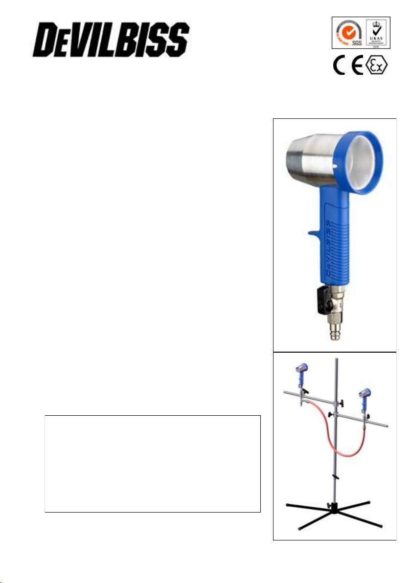
Description
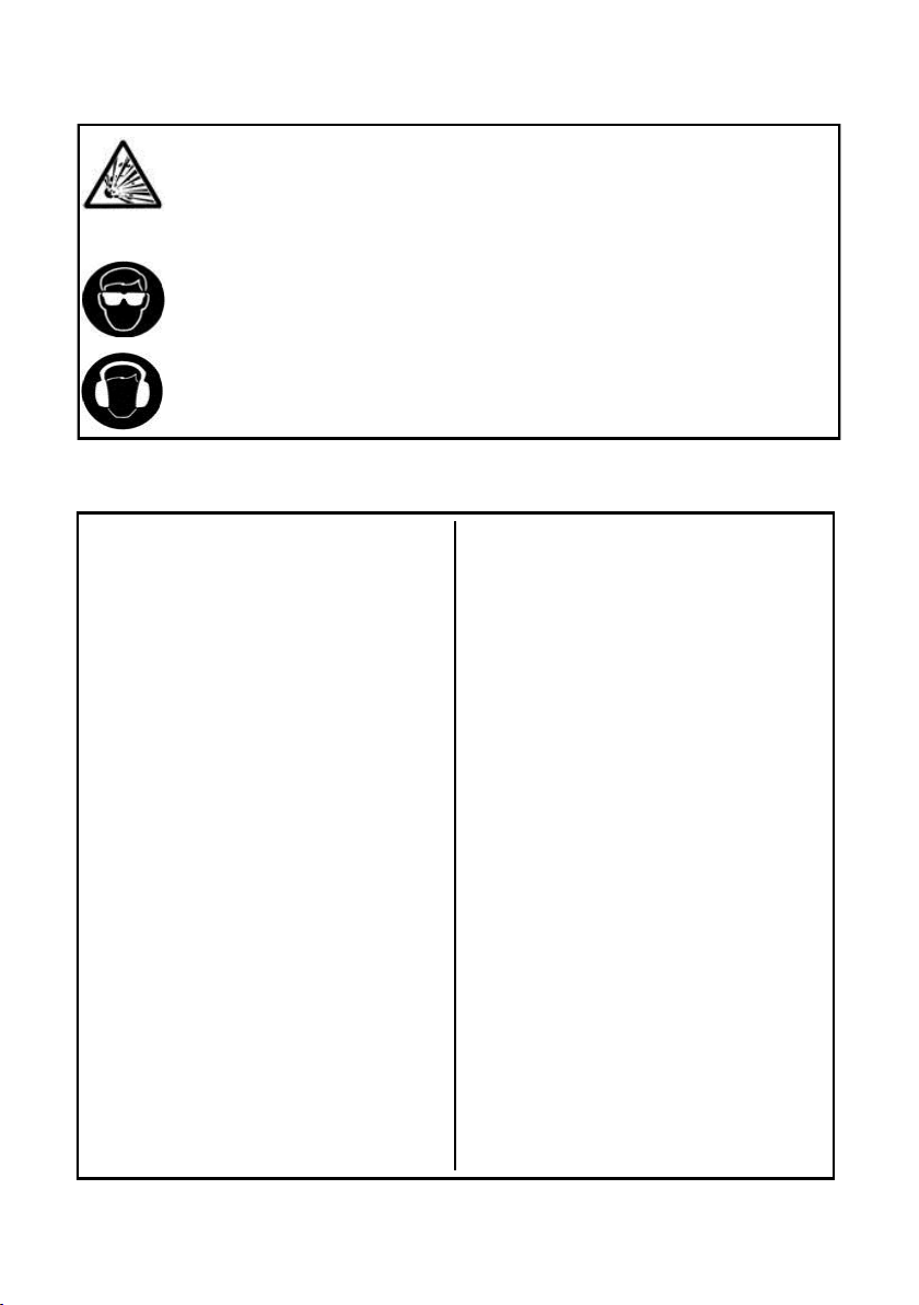
The DMG-620 Dryer System consists of a stand
and 2 DMG-501 Dryer Guns (also available
separately). These products have been developed
for accelerated drying of waterbased paints, to
reduce drying times and increase productivity.
The Dryer uses the Coanda principle, amplifying
the airflow though the device from a low input of air
into the Handle. A replaceable filter is included to
trap any airborne debris from contaminating the
paint finish.
The DMG Air Dyer System complies to ATEX
regulations 94/9/EC, protection level; II 2 G X,
Suitable for use in Zones 1 and 2.
Product Specification
DMG-501 Dryer
Max inlet pressure 7 bar
Typical Air consumption 325 litre/min @
3.5 bar
DMG-520 Stand
Max inlet pressure 7 bar
Hose attachment by QD
1
© 2012 Finishing Brands UK Ltd.
Static Electricity can be generated by air passing though hoses. To prevent such a
risk, earth continuity to the equipment and the object being sprayed should be
maintained. Use conductive hoses and recommended to attach an earth clamp to the
stand upright. Check earth continuity with an ohmmeter, Should be less than 1 MΩ.
Never exceed the max. recommended safe working pressure for the equipment.
Never aim the Dryer at anybody. It is recommended that eye protection is worn when
using this equipment.
The A-weighted sound level of this product may exceed 85 dB (A) depending on the
pressure/airflow being used. Details of actual noise levels are available on request. It
is recommended that ear protection is worn at all times when using this equipment.
Safety Warnings
Installation and Operation
Assembly
1. Fit 4 legs to base (3). Fit lower
stand upright into base and
tighten with thumbscrew. Fit
upper stand upright and tighten
with thumbscrew.
2. Fit thumbscrews to arms (6) and
slide both arms over upright.
Secure with thumbscrew to
required height.
3. Assemble clamp assembly 5A
and 5B as per the diagrams on
P3.
4. Slide clamp assemblies over the
arms (6) and secure with
thumbscrew.
5. Attach hose (7) to the 2 clamp
assemblies.
6. Insert the 2 dryers into the 2
QD’s.
7. Make sure the dryer ball valves
are turned off, then attach the air
supply hose to clamp 5A
8. The Air supply should be filtered,
dry and free from oil (as you
would supply to the spraygun).
The DeVilbiss range of DVFR
Filter/Regulators are
recommended for this.
Operation
1. Turn the Dryer Ball Valves to the
off position.
2. Turn on air supply. Turn on the
Dryer Ball Valves until the
required airflow is achieved. If
more air is required, increase the
pressure at the regulator.
Moving the stand
Grasp the stand and not the dryer
gun handles. This will prevent
accidentally disengaging the quickdisconnect if the system is
pressurised.
© 2012 Finishing Brands UK Ltd.
2
 Loading...