

Page 1
Service Bulletin
SB-2-055-F
by
AIRBRUSH INSTRUCTIONS AND MAINTENANCE
Replaces SB-2-055-E
Thank you for purchasing your DeVilbiss
®
airbrush! You will find that this high
DAGR
quality, versatile airbrush gives the
demanding professional artist the full range
of performance—from spraying fine lines to
wide backgrounds—with a wide range of
materials—from solvent-based automotive
paints to waterbase inks.
DAGR airbrushes are precision made with
micro machining and high quality
materials. Each airbrush is spray tested
before being packaged in its collector’s tin,
assuring that it meets the tough quality
standards you have come to expect from
DeVilbiss. With proper care, your DAGR
airbrush will provide you with excellent
performance to express your creativity.
SPECIFICATIONS
Operating Pressures:
20 to 50 psi
Maximum Inlet Pressure:
175 psi
Airbrush Plating:
Nickel, copper, chrome
Needle Packing:
PTFE (solvent-proof)
GET READY TO SPRAY
SAFETY FIRST
Please read all safety information on pages
8 and 9.
Connect to Compressed Air
Connect your DAGR airbrush to a
regulated air line or select an appropriate
compressor. The DeVilbiss Airblade
single piston compressor is a compact,
economical choice for the beginner and
will provide approximately 25-30 psi of air
pressure to the DAGR airbrush. At 35-40
psi, the DAGR will produce a high paint
flow for shadow, fade, and background
spray, as well as for detail work and fine
lines.
®
Page 2

Page 2 SB-2-055-F
Assemble Airbrush to Compressor
Connect the air hose to the compressor
and airbrush, then turn on the compressor.
If using an Airblade
the pressure to between 20 and 30 psi.
®
compressor, adjust
Listen for any air leaks in the compressor
or air hose fittings. Point the airbrush away
from you and press down on the trigger
(#13) to start the flow of air through the
airbrush. Place a small amount of solvent
or cleaner into the cup and pull back on the
trigger. This will clean out any residual
factory testing material that may still be in
the airbrush.
Mix Paint and Fill the Removable Cup
Follow the paint manufacturer’s
instructions and thin the paint with its
proper solvent. Filter it through a nylon
mesh strainer. It is best to "over-reduce" or
prepare the paint relatively thin and make
continuous passes across your work to
achieve the desired shade. This will also
decrease paint buildup on the needle and
cleaning time. The DAGR features a
removable cup. Depending on the amount
of paint you wish to spray, use the
standard 1/3 oz. (9 cc) cup or select an
optional 1/4 oz. (7 cc) or 1/2 oz. (14 cc) cup.
For small amounts of material, simply
remove the cup and fill the cup socket,
which will give you best visibility for closeup work.
GENERAL OPERATION
The DAGR is a double action airbrush for
fine control. Push the trigger down for air
flow and pull the trigger back for paint
flow. For best results during spraying, keep
air flow even when you have stopped paint
flow.
Air Pressure Range
Working pressures vary between 20 and 50
psi, depending on what type of work is
being done, what spray characteristics are
desired, and paint viscosity. Generally,
thicker paints or higher paint flow will
require higher pressures.
Spraying Fine Lines and Detail
To spray a fine line or detail, press the
trigger down for air flow and pull it back
slightly for paint flow while moving the
airbrush very close to the surface. Control
the thickness of the line by adjusting the
distance between the airbrush and the
surface and by adjusting the amount of
paint flow with the trigger. An even finer
line can be achieved by carefully removing
the crown cap (#1) and moving the
airbrush closer to the surface.
NOTE: The needle and nozzle are very
finely machined. A slight bend on the tip
of the needle can result in an uneven
pattern. The crown cap protects the
needle yet still allows fine lines to be
sprayed.
Wide Lines, Fades, and
Background Spraying
For wider lines, fades, and background
spraying, pull the trigger further back for
more paint flow. Increase the distance
between the airbrush and artwork up to six
inches to control the line width. Increasing
the air pressure will also affect the spray
width. The DAGR will spray a background
width of approximately two inches. Speed
of movement controls the density of the
color and fading effects.
Spraying Lines Without Heavy Ends
To spray a fine or wide line without heavy
ends, start moving the airbrush with the
trigger pushed down for air. Then pull the
trigger back for paint flow at the beginning
of the line and stop paint flow at the end,
but continue the motion of the airbrush.
Page 3

Page 3SB-2-055-F
Stippling (Dots)
Stippling (coarse or fine dots) can add
special textured effects to artwork. Simply
remove the crown cap (#1) and air cap (#2)
and adjust the air pressure between 5 and
50 psi. Lower air pressure will produce
coarse dots; higher pressure will produce
fine dots. Paint viscosity affects stippling,
as well.
Removing Clogs
The cutaway handle (#21) allows the artist
to remove paint buildup from the tip of the
airbrush without removing the handle and
needle. Just grip the exposed needle
locknut (#19) and pull back while pushing
down on the trigger (#13). More paint will
flow past the needle and tip, clearing the
clog.
Another method is to keep a second
airbrush nearby that has solvent in the cup
and use it to spray the nozzle/needle tip.
A third method is to increase the air
pressure and spray solvent through the
airbrush for a short period.
Crown Cap
The crown cap (#1) is used to protect the
needle when spraying a fine line and to
prevent paint build-up and spitting when
spraying large backgrounds.
Pre-Set Handle
The pre-set handle (#21) has a threaded
adjusting knob (#23) on the back that limits
the amount of the trigger pull back and
needle movement. This controls the
amount of paint being sprayed. Reference
markers are on the knob.
CLEANING AND LUBRICATION
Before Each Spray Session
Spray the appropriate solvent or cleaner
through the airbrush to make sure it is
working properly.
To Clean Between Color Changes
Empty the excess paint left in the cup.
Rinse the cup with solvent and use a paper
towel to wipe out any left over paint.
Fill the bottom of the cup with solvent and
spray it through until the spray is clear.
Fill with the next color.
After Each Spray Session
Increase the air pressure and spray
cleaning solution through the airbrush.
This will help thoroughly clean the paint
passages, nozzle, and needle. Remove the
needle and wipe it clean (see below).
Wipe down the outside of the airbrush
with a solvent-dampened cloth, and soak
the crown cap, if needed.
Do not soak the airbrush body in solvent
unless the air valve has been
disassembled and removed. The air valve
o-ring could swell and cause air flow
problems.
To Clean the Needle
Remove the back handle, loosen the
needle locknut (#19), and remove the
needle (#20). Using a soft cloth folded over
the needle, wipe the residue off the needle
by rotating it. Inspect the needle. If it is
bent or mis-shapen, replace it.
Holding the trigger down, carefully reinsert the needle into the airbrush near the
back and push gently until it seats against
the nozzle and is visible through the tip.
You should feel a slight resistance as the
needle passes through the packing (#6).
Page 4

Page 4 SB-2-055-F
If the needle stops suddenly, pull it out and
check the trigger for proper positioning,
then re-insert the needle. Release the
trigger and tighten the needle locknut.
Lubrication
To insure smooth trigger action, periodically
remove the needle and coat it with a highquality lubricant (like DeVilbiss SSL-10
Spray Lube). Wipe the needle with a soft
cloth, leaving it lightly coated. Re-insert the
needle and re-tighten the needle locknut.
Place a few drops of lube in the trigger slot
in the airbrush body.
®
NOTE: Do not use WD-40
oil for lubrication, which will cause the
or light machine
needle to bind as it moves through the PTFE
packing. Do not over-lubricate the needle or
the trigger. The excess lube could be
pushed into the nozzle, causing paint flow
problems.
REPLACEMENT PARTS AND
ACCESSORIES
NOTE: If you must disassemble the
airbrush, please do not use pliers. Tools
are rarely needed. If needed, however, use
a small wrench to unscrew and lightly re-
tighten the head cap (#3), which seats the
nozzle on to the airbrush body. Do not
overtighten!
Nozzle (#4)
If the nozzle becomes worn or damaged, it
must be replaced. Before replacing the
nozzle, protect the needle by pulling it back
slightly. To do this, remove the handle
(#21), loosen the needle locknut (#19), and
carefully pull the needle back through the
nozzle. Remove the head cap (#3) and pull
out the nozzle. If it is stuck, loosen it by
gently pushing the side of it with your
thumb. Pull the nozzle off and replace it
with the new one. Re-assemble the head
cap and tighten it by hand or lightly with a
wrench. Do not over tighten. Re-seat the
needle into the nozzle by gently pushing it
forward until it seats with the fluid nozzle.
Tighten the needle locknut and continue
reassembly.
NOTE: To insure even wear, change the
needle at the same time as the nozzle.
Needle (#20)
DeVilbiss needles are made of precision
machined stainless steel and are designed
for long-term use. However, because of
their long tapers and very fine tips they
can be easily damaged. If the needle point
becomes bent or hooked, it should be
straightened before being pulled back
through the nozzle or the nozzle could
become damaged. If the needle is not bent
too badly, roll it between your finger and a
smooth flat surface to straighten the point.
Quick Disconnect
(Optional Accessory)
A quick disconnect stem is screwed on to
each airbrush and a quick disconnect
adapter is screwed on to the air hose. This
allows for quick changes between
airbrushes using one hose.
Hose
Use high quality, flexible DeVilbiss braided
nylon air hose. Order DGR-123 (802769)
10’ air hose assembly or DGR-124 (802770)
10’ air hose assembly with quick disconnect.
Page 5
TROUBLESHOOTING
CAUSE CORRECTION
Skipping:
1. Air pressure too high 1. Reduce pressure
2. Paint too thick 2. Reduce with solvent
3. Airbrush is dirty 3. Refer to Cleaning in Maintenance
Section
4. Nozzle not seated on body 4. Tighten head cap (by hand or lightly
with wrench)
5. Nozzle damaged or cracked 5. Replace nozzle
6. Dried paint on tip of needle 6. Refer to "To Clean the Needle"
7. Nozzle not centered in air cap 7. Clean nozzle & airbrush seats
Spitting:
1. Dried paint on tip of needle 1. Refer to "To Clean the Needle"
2. Airbrush is dirty 2. Refer to "Cleaning and Lubrication"
3. Paint too thick 3. Reduce with solvent
4. Air pressure too low 4. Increase air pressure
Bubbling in cup
1. Loose head cap or nozzle not 1. Tighten head cap (by hand or lightly
seated on body with wrench)
2. Nozzle damaged or cracked 2. Replace nozzle
Page 5SB-2-055-F
CAUSE CORRECTION
Will Not Spray:
1. Clogged nozzle 1. Refer to "Cleaning and Lubrication"
2. Loose head cap 2. Tighten (by hand or lightly with
wrench)
3. Loose needle locknut 3. Tighten
4. Improper air pressure 4. Adjust
5. Paint too thick 5. Reduce with solvent
6. Nozzle damaged or cracked 6. Replace nozzle
7. Vent hole in cup lid is plugged 7. Unplug with toothpick or brush
Sprays Double Line:
1. Airbrush is dirty 1. Refer to "Cleaning and Lubrication"
2. Bent needle 2. Replace or straighten needle
3. Dirt on tip of nozzle or in air cap 3. Flush with solvent or remove and
soak parts
4. Nozzle damaged or cracked 4. Replace nozzle
5. Dried paint on tip of needle 5. Refer to "To Clean the Needle"
Trigger sticks or does not move smoothly
1. Needs lubrication 1. Refer to "Lubrication"
2. Material leaked past packing 2. Thoroughly clean airbrush (including
trigger) and tighten packing (#6) by
inserting small slotted screwdriver
into airbrush body until it contacts
packing nut. Turn slightly clockwise.
Page 6
Page 6 SB-2-055-F
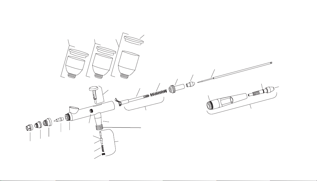
27
13
15
16
17
18
19
5
22
21
20
2524
26
1
2
3
4
5
7
8
6
9
10
11
12
23
Air Inlet 1/8” BPT
Page 7
Page 7SB-2-055-F
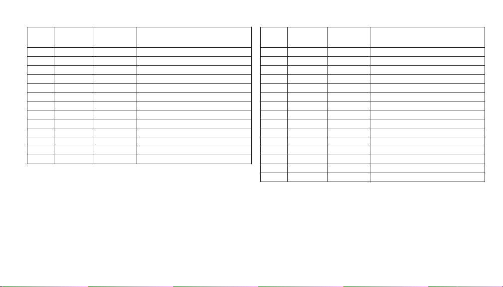
Ref.
No. Order No. Model No. Description
1 802613 DGR-101 Crown cap
2 802615 DGR-103-35 Air cap (for .35mm nozzle)
3 802616 DGR-104 Head cap
4 802618 DGR-105-35 Nozzle (.35mm)
• 5 –– O-ring (head cap & handle)
6 802619 DGR-106K Packing and nut assembly (PTFE)
7 802620 DGR-107 Air valve casing
8 803644 DGR-308K Air valve kit
• 9 –– Air valve o-ring
10 –– Air valve plunger
11 –– Air valve spring
12 –– Air valve nut
13 803645 DGR-323 Trigger
Ref.
No. Order No. Model No. Description
15 802623 DGR-110K Needle guide, rocker, & spring
16 –– Needle guide and rocker
• 17 –– Needle spring
18 802624 DGR-111 Spring guide
19 802625 DGR-112 Needle locknut
20 802627 DGR-113-35 Needle (for .35mm nozzle)
21 802628 DGR-114 Cutaway handle w/pre-set
• 22 –– O-ring (pre-set needle knob)
23 802630 DGR-116 Pre-set needle knob
24 802631 DGR-117 1/4 oz.(7 cc) cup and lid
25 802632 DGR-118 1/3 oz.(9 cc) cup and lid (standard)
26 802633 DGR-119 1/2 oz.(14 cc) cup and lid
27 802634 DGR-120 Cup lid
28 802635 DGR-121K DAGR repair kit
30 802975 DGR-18-K5 O-ring (head cap & handle) kit (5)
• DAGR Repair Kit 802635 (DGR-121K) includes:
Ref. Description Qty.
5 O-ring (head cap & handle) 3
9 Air valve o-ring 2
17 Needle spring 1
22 O-ring (pre-set needle knob) 1
Page 8
Page 8 SB-2-055-F
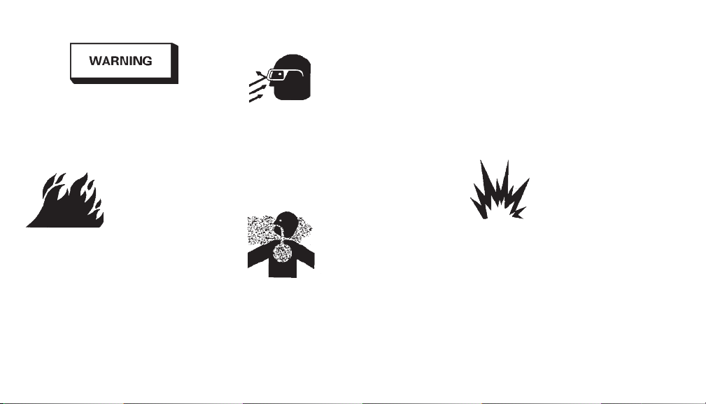
The following hazards may occur
during the normal use of this
equipment. Please read the following
warnings before using this
equipment.
HAZARD: SOLVENT SPRAY
CAUSE: During use and while cleaning and
flushing, solvents can be forcefully
expelled from fluid and air passages.
Some solvents can cause eye injury.
SAFEGUARDS: Wear eye protection.
keep the air free of accumulations of toxic
materials.
Use a mask or respirator whenever there is
a chance of inhaling sprayed materials.
The mask must be compatible with the
material being sprayed and its
concentration. Equipment must be as
prescribed by an industrial hygienist or
safety expert, and be NIOSH approved.
HAZARD: FIRE
CAUSE: Solvent and coatings can be
highly flammable or combustible
especially when sprayed.
SAFEGUARDS: Adequate exhaust must be
provided to keep air free of accumulations
of flammable vapors.
Smoking must never be allowed in the
spray area.
Fire extinguishing equipment must be
present in the spray area.
HAZARD: INHALING TOXIC SUBSTANCES
CAUSE: Certain materials may be harmful
if inhaled, or if there is contact with the
skin.
SAFEGUARDS: Follow the requirements of
the Material Safety Data Sheet supplied by
your coating material manufacturer.
Adequate exhaust must be provided to
HAZARD: EXPLOSION HAZARD –
INCOMPATIBLE MATERIALS
CAUSE: Halogenated hydrocarbon solvents
– for example; methylene chloride and
1,1,1, – Trichloroethane are not chemically
compatible with the aluminum that might
be used in many system components. The
chemical reaction caused by these
solvents reacting with aluminum can
become violent and lead to an equipment
explosion.
SAFEGUARDS: Guns with stainless steel
internal passageways may be used with
Page 9

Page 9SB-2-055-F
these solvents. However, aluminum is
widely used in other spray application
equipment – such as material pumps,
regulators, valves, and this gun and cup.
Check all equipment items before use and
make sure they can also be used safely
with these solvents. Read the label or data
sheet for the material you intend to spray.
If in doubt as to whether or not a coating or
cleaning material is compatible, contact
your material supplier.
HAZARD: GENERAL SAFETY
CAUSE: Improper operation or
maintenance of equipment.
SAFEGUARDS: Operators should be given
adequate training in the safe use and
maintenance of the equipment (in
accordance with the requirements of
NFPA-33, Chapter 15). Users must comply
with all local and national codes of practice
and insurance company requirements
governing ventilation, fire precautions,
operation, maintenance, and house keeping. These are OSHA Sections 1910.94
and 1910.107 and NFPA-33.
HAZARD: CUMULATIVE TRAUMA
DISORDERS ("CTD'S")
CTD's, or musculoskeletal disorders,
involve damage to the hands, wrists,
elbows, shoulders, neck, and back. Carpal
tunnel syndrome and tendonitis (such as
tennis elbow or rotator cuff syndrome) are
examples of CTD's.
CAUSE: Use of hand tools may cause
cumulative trauma disorders ("CTD's").
CTD's, when using hand tools, tend to
affect the upper extremities. Factors which
may increase the risk of developing a CTD
include:
1. High frequency of the activity.
2. Excessive force, such as gripping,
pinching, or pressing with the hands
and fingers.
3. Extreme or awkward finger, wrist, or
arm positions.
4. Excessive duration of the activity.
5. Tool vibration.
6. Repeated pressure on a body part.
7. Working in cold temperatures.
CTD's can also be caused by such activities
as sewing, golf, tennis, and bowling, to
name a few.
SAFEGUARDS: Pain, tingling, or numb ness in the shoulder, forearm, wrist,
hands, or fingers, especially during the
night, may be early symptoms of a CTD.
Do not ignore them. Should you exper ience
any such symptoms, see a physician
immediately. Other early symptoms may
include vague discomfort in the hand, loss
of manual dexterity, and nonspecific pain
in the arm. Ignoring early symptoms and
continued repetitive use of the arm, wrist,
and hand can lead to serious disability.
Risk is reduced by avoiding or lessening
factors 1-7.
Page 10

Page 10 SB-2-055-F
NOTES
Page 11

Boletín de mantenimiento
SB-2-055-F
por
INSTRUCCIONES Y MANTENIMIENTO DEL AERÓGRAFO
Substituye SB-2-055-E
¡Gracias por su compra del aerógrafo
DAGR®de DeVilbiss! Usted encontrará que
este aerógrafo versátil y de alta calidad
proporciona al artista profesional exigente
una gama completa—de rendimiento para
atomizar desde líneas finas hasta fondos
amplios—con una gama amplia de
materiales—desde pinturas a base de
solventes para automotores hasta tintas a
base de agua.
Los aerógrafos DAGR son instrumentos de
precisión hechos con micromaquinado y
materiales de alta calidad. Cada aerógrafo
se prueba atomizando antes de empacarlo
en su lata de colección, asegurando que
cumpla con los estándares de calidad
estrictos que usted ha llegado a esperar de
DeVilbiss. Con el debido cuidado, su
aerógrafo DAGR le ofrecerá un
rendimiento excelente para expresar su
creatividad.
ESPECIFICACIONES
Presiones operativas:
de 20 a 50 psi
Presión de admisión máxima:
175 psi
Enchapado del aerógrafo:
Níquel, cobre, cromo
Empaquetamiento de la aguja:
PTFE (a prueba de solvente)
PREPÁRESE PARA ATOMIZAR
SEGURIDAD ANTE TODO
Sírvase leer toda la información de
seguridad en las páginas 18 y 19.
Conexión al aire comprimido
Conecte su aerógrafo DAGR a una línea
neumática regulada o seleccione un
compresor apropiado. El compresor
®
Airblade
es una opción compacta y económica para
el principiante y le dará aproximadamente
de 25 a 30 psi de presión neumática al
aerógrafo DAGR. Operando de 35 a 40 psi,
el aerógrafo DAGR producirá un alto flujo
de pintura para sombrear, difuminar y
crear fondos, así como para trabajos
detallados y líneas finas.
de DeVilbiss con un solo pistón
Page 12

Página 12 SB-2-055-F
Ensamblaje del aerógrafo al compresor
Conecte la manguera neumática al
compresor y aerógrafo, luego active el
compresor. Si está usando el compresor
®
Airblade
psi. Escuche cualquier filtración de aire en
el compresor o los accesorios de la
manguera neumática. Oriente el aerógrafo
lejos de usted y pulse el disparador (#13)
para empezar el flujo de aire a través del
aerógrafo. Ponga una pequeña cantidad
de solvente o limpiador en la taza y tire el
disparador hacia atrás. Esto limpiará
cualquier material remanente de la prueba
en fábrica que pudiera haber en el
aerógrafo.
Mezcla de pintura y relleno de la taza
desmontable
Siga las instrucciones del fabricante de la
pintura y diluya la pintura con el solvente
apropiado. Fíltrela usando un tamizador de
malla de nylon. Es mejor “sobrerreducir” o
preparar la pintura relativamente diluida y
hacer pases continuos en su trabajo para
lograr el matiz deseado. Esto también
disminuirá la acumulación de pintura en la
aguja y el tiempo de limpieza. El aerógrafo
DAGR cuenta con una taza desmontable.
Dependiendo de la cantidad de pintura que
desea atomizar, utilice la taza estándar de
9 cc (1/3 oz.) o seleccione la taza opcional
de 7 cc (1/4 oz.) ó 14 cc (1/2 oz.). Para
pequeñas cantidades de material, no tiene
, ajuste la presión entre 20 y 30
más que sacar la taza y llenar el encaje de
la taza, lo cual le dará mejor visibilidad
para trabajos detallados de cerca.
FUNCIONAMIENTO GENERAL
El aerógrafo DAGR es un instrumento de
doble acción para control fino. Pulse el
disparador para que fluya el aire y tire del
disparador hacia atrás para que fluya la
pintura. Para mejores resultados durante
la atomización, mantenga el flujo de aire
uniforme aún cuando haya detenido el
flujo de pintura.
Autonomía de la presión neumática
Las presiones de trabajo varían entre 20 y
50 psi, dependiendo del tipo de trabajo
que se está haciendo, las características
deseadas al atomizar y la viscosidad de la
pintura. Generalmente, las pinturas más
espesas o el flujo de pintura más alto
requerirá presiones mayores.
Atomización de líneas finas y detalles
Para atomizar una línea fina o detalle,
pulse el disparador para que fluya el aire y
tírelo ligeramente hacia atrás para que
fluya la pintura al tiempo que mueve el
aerógrafo muy cerca de la superficie.
Controle el espesor de la línea ajustando la
distancia entre el aerógrafo y la superficie,
y ajustando la cantidad de flujo de pintura
con el disparador. Puede lograrse una
línea aún más fina quitando
cuidadosamente el sombrerete superior
(#1) y moviendo el aerógrafo más cerca de
la superficie.
NOTA: La aguja y la boquilla están están
maquinadas con mucha precisión. Una
leve curvatura en la punta de la aguja
puede producir un patrón disparejo. El
sombrerete superior protege la aguja y aún
así permite que se atomicen líneas finas.
Atomización de líneas anchas,
difuminaciones y fondos
Para atomizar líneas más anchas,
difuminaciones y fondos, tire del
disparador más hacia atrás para que fluya
más pintura. Aumente la distancia entre el
aerógrafo y el material gráfico hasta 15,24
cm (6 pulg.) para controlar el ancho de la
línea. Aumentar la presión neumática
también afectará el ancho de lo atomizado.
El aerógrafo DAGR atomizará un ancho de
fondo de aproximadamente 5 cm (2 pulg.).
La velocidad del movimiento controla la
densidad del color y los efectos de
difuminación.
Atomización de líneas sin terminaciones
gruesas
Para atomizar una línea fina o ancha sin
terminación gruesa, comience moviendo
el aerógrafo manteniendo el disparador
pulsado para que fluya el aire. A
continuación, tire del disparador hacia
Page 13

Página 13SB-2-055-F
atrás para que fluya la pintura al comienzo
de la línea y detenga el flujo de pintura al
final, pero continúe el movimiento del
aerógrafo.
Moteado (lunares)
El moteado (lunares finos o gruesos)
pueden añadir efectos especiales de
textura al material gráfico. Nada más retire
el sombrerete superior (#1) y el
sombrerete de aire (#2) y ajuste la presión
del aire entre 5 y 50 psi. Reducir la presión
del aire producirá lunares gruesos; las
presiones mayores producirán lunares
finos. De igual manera, la viscosidad de la
pintura afecta el moteado.
Eliminación de obstrucciones
El asa de corte (#21) permite al artista
eliminar la acumulación de pintura de la
punta del aerógrafo sin quitar el asa ni la
aguja. Sólo agarre la contratuerca de la
aguja (#19) expuesta y tire hacia atrás
mientras mantiene el disparador (#13)
pulsado. Más pintura fluirá por la aguja y
punta, destapando la obstrucción.
Otro método es mantener un segundo
aerógrafo cerca que contenga solvente en
la taza y usarlo para atomizar la punta de
la boquilla/aguja.
Un tercer método es aumentar la presión
del aire y atomizar solvente por el
aerógrafo por un período breve.
Sombrerete superior
El sombrerete superior (#1) se usa para
proteger la aguja al atomizar una línea fina
y para prevenir la acumulación y escurrido
de la pintura al atomizar fondos grandes.
Asa preprogramada
El asa preprogramada (#21) tiene un botón
de ajuste roscado (#23) en la parte
posterior que limita cuanto puede tirarse
del disparador hacia atrás y el movimiento
de la aguja. Esto controla la cantidad de
pintura que se atomiza. El botón tiene
marcas de referencia.
LIMPIEZA Y LUBRICACIÓN
Antes de cada sesión de atomización
Atomice el solvente o limpiador apropiado
por el aerógrafo para asegurarse de que
esté funcionando como es debido.
Limpieza entre cambios de colores
Vacíe la pintura sobrante en la taza. Aclare
la taza con solvente y use un papel toalla
para limpiar cualquier remanente de
pintura. Llene el fondo de la taza con
solvente y atomícelo totalmente hasta que
el espray esté claro. Llene con el siguiente
color.
Después de cada sesión de atomización
Aumente la presión del aire y atomice el
aerógrafo con una solución limpiadora.
Esto ayudará a limpiar a fondo los pasajes
de pintura, la boquilla y la aguja. Saque la
aguja y límpiela con un paño (ver abajo).
Limpie la parte externa del aerógrafo con
un paño humedecido con solvente y
ponga en remojo el sombrerete superior,
si es necesario.
No ponga en remojo el cuerpo del
aerógrafo en solvente a menos que se
haya desarmado y sacado la válvula de
aire. La junta tórica de la válvula de aire
puede hincharse y causar problemas de
flujo de aire.
Limpieza de la aguja
Quite el asa posterior, afloje la
contratuerca de la aguja (#19) y saque la
aguja (#20). Usando un paño suave
doblado sobre la aguja, limpie cualquier
residuo en la aguja haciéndola girar.
Inspeccione la aguja. Si está curvada o
deformada, reemplácela.
Manteniendo el disparador oprimido,
reinserte con cuidado la aguja en el
aerógrafo cerca de la parte posterior y
empújela suavemente hasta que quede
asentada en la boquilla y sea visible a
través de la punta. Debe sentir una
resistencia leve cuando la aguja pasa por
Page 14

Página 14 SB-2-055-F
el empaquetamiento (#6). Si la aguja se
detiene de repente, sáquela y verifique el
debido posicionamiento del disparador,
luego reinserte la aguja. Deje de oprimir el
disparador y ajuste la contratuerca de la
aguja.
Lubricación
Para asegurar que el disparador se accione
sin problemas, saque periódicamente la
aguja y cúbrala con un lubricante de alta
calidad (como el lubricante en atomizador
SSL-10 de DeVilbiss). Limpie la aguja con un
paño suave dejándola ligeramente
recubierta. Reinserte la aguja y reajuste la
contratuerca de la aguja. Ponga unas
cuantas gotas del lubricante en la ranura del
disparador en el cuerpo del aerógrafo.
NOTA: Para lubricación, no utilice WD-40
aceite liviano para máquinas porque esto
hará que la aguja ponga cierta resistencia a
medida que se mueva por el
empaquetamiento de PTFE. No lubrique
demasiado la aguja ni el disparador. El
lubricante excedente podría ser empujado a
la boquilla, lo que causaría problemas de
flujo de pintura.
®
REPUESTOS Y ACCESORIOS
NOTA: Si debe desarmar el aerógrafo, por
favor no utilice alicates. Rara vez se
necesita usar herramientas. Sin embargo,
si lo necesita utilice una llave inglesa
pequeña para destornillar y reajuste
suavemente el sombrerete cabecero (#3),
que sirve para asentar la boquilla en el
cuerpo del aerógrafo. ¡No ajuste
demasiado!
Boquilla (#4)
Si la boquilla se desgasta o daña, debe
reemplazarse. Antes de reemplazar la
boquilla, proteja la aguja tirándola un poco
hacia atrás. Para hacer esto, quite el asa
(#21), afloje la contratuerca de la aguja
(#19) y tire con cuidado de la aguja hacia
atrás a través de la boquilla. Quite el
sombrerete cabecero (#3) y saque la
boquilla. Si está atascada, aflójela
empujando suavemente su costado con el
dedo pulgar. Saque la boquilla y
reemplácela con una nueva. Reensamble
o
el sombrerete cabecero y ajústelo a mano
o suavemente con una llave inglesa. No lo
ajuste demasiado. Vuelva a asentar la
aguja en la boquilla empujándola con
cuidado hacia adelante hasta que quede
asentada con la boquilla de fluido. Ajuste
la contratuerca de la aguja y continúe
reensamblando.
NOTA: Para asegurar un uso parejo,
cambie la aguja al mismo tiempo que la
boquilla.
Aguja (#20)
Las agujas DeVilbiss están hechas de
acero inoxidable maquinado con precisión
y están diseñadas para uso por largo
tiempo. Sin embargo, debido a sus puntas
muy finas y su longitud ahusada pueden
dañarse fácilmente. Si la punta de la aguja
se pone curva o ganchuda, debe
enderezarse antes de sacarla por la
boquilla o la boquilla podría resultar
dañada. Si la aguja no está muy curvada,
hágala rodar entre su dedo y una
superficie lisa y plana para enderezar la
punta.
Dispositivo de desconexión rápida
(accesorio opcional)
Un vástago de desconexión rápida está
atornillado en cada aerógrafo y un
adaptador de desconexión rápida está
atornillado en la manguera neumática.
Esto permite hacer cambios rápidos entre
aerógrafos usando una manguera.
Manguera
Use la manguera neumática flexible, de alta
calidad y de nylon trenzado de DeVilbiss.
Pida la unidad de manguera neumática de
3 metros (10 pies) (3 DGR-123 (802769) o la
unidad de manguera neumática de 3 metros
(10 pies) con dispositivo de desconexión
rápida DGR-124 (802770).
Page 15

LOCALIZACIÓN Y SOLUCIÓN DE PROBLEMAS
CAUSA CORRECCIÓN
Pintura irregular:
1. Presión del aire demasiado alta 1. Reduzca la presión
2. Pintura demasiado espesa 2. Reducir con solvente
3. Aerógrafo sucio 3. Remítase a Limpieza en la sección
4. Boquilla no asentada en el cuerpo 4. Ajuste el sombrerete cabecero (a
5. Boquilla dañada o rajada 5. Reemplace la boquilla
6. Pintura seca en la punta de 6. Remítase a “Limpieza de la aguja”
la aguja
7. Boquila descentrada en el 7. Limpie la boquilla y los asientos
sombrerete de aire del aerógrafo
Pintura escurrida:
1. Pintura seca en la punta de 1. Remítase a “Limpieza de la aguja”
la aguja
2. Aerógrafo sucio 2. Remítase a “Limpieza y lubricación”
3. Pintura demasiado espesa 3. Reducir con solvente
4. Presión del aire demasiado baja 4. Aumentar la presión del aire
Formación de burbujas en
la taza
1. Afloje el sombrerete cabecero o 1. Ajuste el sombrerete cabecero
boquilla no asentada en (a mano o suavemente con
el cuerpo llave inglesa)
2. Boquilla dañada o rajada 2. Reemplace la boquilla
de Mantenimiento
mano o suavemente con llave
inglesa)
Página 15SB-2-055-F
CAUSA CORRECCIÓN
No atomiza:
1. Boquilla obstruida 1. Remítase a “Limpieza y lubricación”
2. Sombrerete cabecero flojo 2. Ajústelo (a mano o suavemente con
3. Contratuerca de la aguja floja 3. Ajústela
4. Presión del aire indebida 4. Ajústela
5. Pintura demasiado espesa 5. Reducir con solvente
6. Boquilla dañada o rajada 6. Reemplace la boquilla
7. Agujero de ventilación en la tapa 7. Desatasque con un mondadientes
de la taza bloqueado o cepillo
Atomiza líneas dobles:
1. Aerógrafo sucio 1. Remítase a “Limpieza y lubricación”
2. Aguja curvada 2. Reemplace o enderece la aguja
3. Suciedad en la punta de la 3. Purgue con solvente o quite las
boquilla o en el sombrerete de aire piezas y remójelas
4. Boquilla dañada o rajada 4. Reemplace la boquilla
5. Pintura seca en la punta de 5. Remítase a “Limpieza de la aguja”
la aguja
Disparador atascado o no se mueve sin problemas
1. Necesita lubricación 1. Remítase a “Lubricación”
2. Material filtrado más allá 2. Limpie el aerógrafo a fondo
del empaquetamiento
llave inglesa)
(incluyendo el disparador) y ajuste el
empaquetamiento (#6) insertando un
destornillador pequeño ranurado en el
cuerpo del aerógrafo hasta que haga
contacto con la tuerca del empaquetamiento. Haga girar un poco en sentido horario.
Page 16

Página 16 SB-2-055-F
27
13
15
16
17
18
19
5
22
21
20
2524
26
1
2
3
4
5
7
8
6
9
10
11
12
23
Entrada de aire 1/8” BPT
Page 17

Página 17SB-2-055-F
No. de
Ref. Pida el No. No. de modelo Descripción
1 802613 DGR-101 Sombrerete superior
2 802615 DGR-103-35
3 802616 DGR-104 Sombrerete cabecero
4 802618 DGR-105-35 Boquilla (0,35 mm)
• 5 –– Junta tórica (sombrerete cabecero y asa)
6 802619 DGR-106K
7 802620 DGR-107 Cubierta de la válvula de aire
8 803644 DGR-308K Kit de válvula de aire
• 9 –– Junta tórica de la válvula de aire
10 –– Émbolo de la válvula de aire
11 –– Resorte de la válvula de aire
12 –– Tuerca de la válvula de aire
13 803645 DGR-323 Disparador
Sombrerete de aire (para boquilla de 0,35 mm)
Unidad de empaquetamiento y tuerca (PTFE)
No. de
Ref. Pida el No. No. de modelo Descripción
15 802623 DGR-110K Guía de la aguja, balancín y resorte
16 –– Guía de la aguja y balancín
• 17 –– Resorte de la aguja
18 802624 DGR-111 Guía de resorte
19 802625 DGR-112 Contratuerca de la aguja
20 802627 DGR-113-35 Aguja (para boquilla de 0,35 mm)
21 802628 DGR-114 Asa de corte preprogramada
• 22 ––
23 802630 DGR-116 Botón preprogramado de aguja
24 802631 DGR-117 Taza de 7 cc (1/4 oz.) y tapa
25 802632 DGR-118 Taza de 9 cc (1/3 oz.) y tapa (estándar)
26 802633 DGR-119 Taza de 14 cc (1/2 oz.) y tapa
27 802634 DGR-120 Tapa de taza
28 802635 DGR-121K Kit de reparación para el aerógrafo DAGR
30 802975 DGR-18-K5
• El kit de reparación 802635 para el aerógrafo DAGR (DGR-121K) incluye:
Ref. Descripción Cantidad
5 Junta tórica (sombrerete cabecero y asa) 3
Junta tórica
9
17 Resorte de la aguja 1
22 Junta tórica (botón preprogramado de aguja) 1
de la válvula de aire 2
Junta tórica (botón preprogramado de aguja)
Kit de junta tórica (sombrerete cabecero y asa) (5)
Page 18

Página 18 SB-2-055-F
ADVERTENCIA
Durante el uso normal de este
equipo pueden ocurrir las siguientes
situaciones de peligro. Sírvanse leer
las siguientes advertencias antes de
usar este equipo.
PELIGRO: ATOMIZACIÓN DE SOLVENTE
CAUSA: Durante el uso y mientras se
limpia y purga, los solventes pueden
expulsarse con fuerza de los pasajes de
fluido y aire. Algunos solventes pueden
causar lesiones en los ojos.
MEDIDAS PREVENTIVAS: Use gafas de
protección.
Debe proveerse de un escape adecuado
para mantener el aire libre de
acumulaciones de vapores tóxicos.
Use una máscara o respirador siempre que
haya riesgo de inhalar materiales
atomizados. La máscara debe ser
compatible con el material que se atomiza
y su concentración. El equipo debe ser
como el recomendado por un higienista
industrial o experto en seguridad y
aprobado por NIOSH.
PELIGRO: INCENDIO
CAUSA: El solvente y los recubrimientos
pueden ser altamente inflamables o
combustibles especialmente cuando se
atomizan.
MEDIDAS PREVENTIVAS: Debe proveerse
de un escape adecuado para mantener el
aire libre de acumulaciones de vapores
inflamables.
Nunca debe permitirse fumar en el área
donde se atomiza.
En el área donde se atomiza debe haber
equipo extintor de incendios.
PELIGRO: INHALACIÓN DE SUSTANCIAS
TÓXICAS
CAUSA: Ciertos materiales pueden ser
dañinos si se inhalan o si tienen contacto
con la piel.
MEDIDAS PREVENTIVAS: Siga los
requisitos de la Hoja de datos de
seguridad (MSDS) suministrada por el
fabricante del material de recubrimiento.
PELIGRO: PELIGRO DE EXPLOSIÓN –
MATERIALES INCOMPATIBLES
CAUSA: Solventes de hidrocarburos
halogenados – por ejemplo; cloruro de
metileno y tricloretano-1,1,1 no son
compatibles químicamente con el
aluminio que pudiera ser usado en
muchos componentes del sistema. La
reacción química causada por estos
solventes reaccionando con el aluminio
puede tornarse violenta y producir una
explosión del equipo.
MEDIDAS PREVENTIVAS: Las pistolas con
pasajes internos de acero inoxidable
Page 19

Página 19SB-2-055-F
pueden usarse con estos solventes. Sin
embargo, en otros equipos de
atomizadores suele utilizarse el aluminio –
como bombas de material, reguladores,
válvulas y esta pistola y taza. Revise todos
los componentes del equipo antes de
usarlos y asegúrese de que puedan usarse
sin peligro con estos solventes. Lea la
etiqueta u hoja de seguridad para el
material que piensa atomizar. Si tiene
dudas sobre si un recubrimiento o material
de limpieza es compatible o no, póngase
en contacto con el proveedor del material.
PELIGRO: SEGURIDAD EN GENERAL
CAUSA: Operación o mantenimiento
indebidos del equipo.
MEDIDAS PREVENTIVAS: Los usuarios
deben recibir una capacitación adecuada
en el uso y mantenimiento seguro del
equipo (de acuerdo con los requisitos de
NFPA-33, Capítulo 15). Los usuarios deben
cumplir con todos los códigos locales y
nacionales de práctica y los requisitos de
las compañías de seguro sobre
ventilación, precauciones de incendio,
operación, mantenimiento y limpieza del
lugar de trabajo. Estas son las Secciones
1910.94 y 1910.107 de OSHA y NFPA-33.
PELIGRO: TRASTORNOS TRAUMÁTICOS
ACUMULATIVOS (“CTD”)
Los CTD, o trastornos musculoesqueléticos,
implican daño a las manos, las muñecas, los
codos, los hombros, el cuello y la espalda.
Ejemplos de los CTD son el síndrome de
túnel carpiano y la tendonitis (como el codo
de tenista o el síndrome del manguito
rotador).
CAUSA: El uso de herramientas manuales
puede causar trastornos traumáticos
acumulativos (“CTD”).
Cuando se usan herramientas manuales,
los CTD tienden a afectar las extremidades
superiores. Los factores que pueden
aumentar el riesgo de desarrollar un CTD
incluyen:
1. Alta frecuencia de la actividad.
2. Fuerza excesiva, p. ej. al agarrar, apretar
u oprimir con las manos y dedos.
3. Posiciones extremas o forzadas de los
dedos, la muñeca o los brazos.
4. Duración excesiva de la actividad.
5. Vibración de la herramienta.
6. Presión repetida en una parte del cuerpo.
7. Trabajar en temperaturas frías.
Los CTD también pueden ser causados por
actividades como coser, jugar golf, tenis y
bolos por mencionar algunas.
MEDIDAS PREVENTIVAS: Un dolor,
hormigueo o entumecimiento en el
hombro, el antebrazo, las muñecas, las
manos o los dedos, especialmente durante
la noche, pueden ser síntomas tempranos
de un CTD. No los ignore. Si experimenta
cualquiera de dichos síntomas, vea de
inmediato a un médico. Otros síntomas
tempranos pueden incluir molestias en las
manos, pérdida de dexteridad manual y un
dolor no específico en el brazo. Ignorar los
síntomas tempranos y continuar usando
repetitivamente los brazos, las muñecas y
las manos puede conducir a una
discapacidad grave. El riesgo se disminuye
evitando o reduciendo los factores listados
del 1 al 7.
Page 20

Página 20 SB-2-055-F
NOTAS
Page 21

Bulletin de service
SB-2-055-F
par
MODE D’EMPLOI ET ENTRETIEN DE L’AÉROGRAPHE
Remplace SB-2-055-E
Merci d’avoir acheté l’aérographe DeVilbiss
®
! Vous trouverez que cet aérographe
DAGR
polylvalent de haute qualité offre à l’artiste
professionnel et exigeant la gamme
complète de performance—de la
pulvérisation de lignes minces aux arrièreplans larges—avec une gamme généreuse
de matériaux—allant des peintures
automobile à base de diluants jusqu’aux
encres à base d’eau.
Les aérographes DAGR de précision sont
micro-usinés et fabriqués de matériaux de
qualité supérieure. Le pulvérisateur de
chaque aérographe est testé avant d’être
emballé dans sa boîte de collection, ce qui
assure qu’il répond aux normes de qualité
exigeantes de DeVilbiss. Entretenu
correctement, votre aérographe DAGR
vous offrira une performance excellente
pour exprimer votre créativité.
CARACTÉRISTIQUES
Pressions de fonctionnement :
20 à 50 psi
Pression d’entrée maximum :
175 psi
Revêtement de l’aérographe :
Nickel, cuivre, chrome
Emballage de l’aiguille :
PTFE (à l’épreuve des solvents)
PRÉPAREZ-VOUS À PULVÉRISER
LA SÉCURITÉ D’ABORD
Veuillez lire toutes les informations sur la
sécurité sur les pages 28 et 29.
Connexion à l’air comprimé
Connectez votre aérographe DAGR à la
conduite d’air régulée ou choisissez un
compresseur approprié. Le compresseur à
piston simple Airblade
choix du débutant compact et économique
qui fournit à l’aérographe DAGR environ
25 à 30 psi de pression d’air. Avec 35 à 40
psi, le DAGR produira un débit élevé pour
l’effet d’ombrage, de fond et de dégradé
de teintes, ainsi que pour le travail détaillé
et les lignes fines.
®
de DeVilbiss est le
Page 22

Page 22 SB-2-055-F
Montage de l’aérographe sur le compresseur
Branchez le conduit d’air sur le compresseur
et sur l’aérographe et mettez le compresseur
sous tension. Si vous utilisez un
compresseur Airblade
entre 20 et 30 psi. Écoutez attentivement
pour toute fuite d’air dans le compresseur
ou dans les raccords du conduit d’air.
Pointez l’aérographe loin de vous et
appuyez sur la gâchette (#13) pour amorcer
le débit d’air dans l’aérographe. Placez une
petite quantité de diluant ou de produit
nettoyant dans le godet et tirez sur la
gâchette. Cette action nettoiera tout résidu
de matériau d’épreuve en usine qui pourrait
se trouver dans l’aérographe.
Mélanger la peinture et remplir le godet
amovible
Suivez les instructions du fabricant de
peinture et éclaircissez la peinture au
moyen du diluant approprié. Filtrez-la dans
une passoire en nylon. Il est mieux de “surréduire”, ou de péparer une peinture
relativement claire et d’effectuer des
passes en continu sur le travail pour
obtenir la teinte désirée. Cela réduira
également l’accumulation de peinture sur
l’aiguille ainsi que le temps de nettoyage.
Le DAGR est doté d’un godet amovible.
Selon la quantité de peinture que vous
désirez pulvériser, utilisez le godet
standard 9cc (1/3 oz) ou choisissez un
®
, réglez la pression
godet facultatif de 7cc (1/4 oz) ou 14cc (1/2
oz). Pour de petites quantités de peinture,
retirez simplement le godet et remplissez la
douille du godet, ce qui vous donnera une
meilleure visibilité pour le travail de près.
FONCTIONNEMENT GÉNÉRAL
Le DAGR est un aérographe à double
action pour le contrôle raffiné. Tirez la
gâchette vers le bas pour le débit d’air et
tirez la gâchette vers l’arrière pour le débit
de peinture. Pour les meilleurs résultats
lors de la pulvérisation, maintenez un débit
d’air régulier même lorsque vous arrêtez le
débit de peinture.
Plage de pression d’air
Les pressions de fonctionnement varient
entre 20 et 50 psi en fonction du genre de
travail effectué, des caractéristiques de
pulvérisation désirés, et de la viscosité de
la peinture. En général, les peintures plus
épaisses ou le débit de peinture élevé
exigent des pressions plus élevées.
Pulvérisation de lignes fines et détaillées
Pour pulvériser une ligne fine ou détaillée,
tirez la gâchette vers le bas pour le débit
d’air et tirez-la légèrement vers l’arrière
pour le débit de peinture tout en déplaçant
le pistolet très près de la surface. Contrôlez
l’épaisseur de la ligne en ajustant la
distance entre le pistolet et la surface et en
ajustant le débit de peinture au moyen de
la gâchette. Vous pouvez obtenir une ligne
encore plus fine si vous enlevez le
capuchon (#1) et placez le pistolet plus
près de la surface.
REMARQUE : L’aiguille et la buse sont
finement usinées. Une courbe, même
légère, du bout de l’aiguille peut causer
une pulvérisation inégale. Le capuchon
protège l’aiguille tout en permettant la
pulvérisation de lignes fines.
Pulvérisation de lignes larges, de fonds et
de dégradés de teintes
Pour des lignes larges, des fonds et des
dégradés de teintes, tirez la gâchette plus
loin pour un débit de peinture plus élevé.
Augmentez d’environ six pouces la
distance entre l’aérographe et le travail
afin de contrôler la largeur de la ligne.
Augmenter la pression d’air affectera
également la largeur de la pulvérisation.
Le DAGR pulvérisera un fond d’une largeur
d’environ deux pouces. La vitesse de
mouvement contrôle l’intensité de la
couleur et des dégradés de teintes.
Tracer des lignes sans dégâts
Pour tracer une ligne fine ou large sans
dégâts, commencez par déplacer
Page 23

Page 23SB-2-055-F
l’aérographe avec la gâchette enfoncée
pour l’air. Ensuite tirez sur la gâchette pour
le débit de peinture au début de la ligne et
arrêtez le débit de peinture à la fin mais
continuez le mouvement de l’aérographe.
Pointillage
Le pointillage (gros ou petits pois) peut
ajouter un effect texturisé à l’oeuvre.
Retirez simplement le capuchon (#1) et le
chapeau d’air (#2) et réglez la pression d’air
entre 5 et 50 psi. Une pression faible
produira de gros pois ; une pression élevée
produira de petits pois. La viscosité de la
peinture affecte également le pointillage.
Décrassage
Le levier (#21) permet à l’artiste de retirer
l’accumulation de peinture de l’embout de
l’aérographe sans enlever la poignée et
l’aiguille. Grippez le contre-écrou exposé
de l’aiguille (#19) et tirez dessus tout en
appuyant sur la gâchette (#13). Une plus
grande quantité de peinture s’écoulera de
l’aiguille et de l’embout et débouchera
ainsi l’accumulation de peinture.
Une autre méthode serait d’avoir à portée
de la main un deuxième aérographe
comportant du diluant dans son godet que
vous pourrez utiliser pour vaporiser
l’embout de la buse / de l’aiguille.
Une troisième méthode est d’augmenter la
pression d’air et de vaporiser du diluant dans
l’aérographe pendant une courte durée.
Capuchon
Le capuchon (#1) sert à protéger l’aiguille
lorsque vous vaporisez une ligne fine ainsi
qu’à prévenir l’accumulation et les crachotis
lorsque vous réalisez de grands fonds.
Levier de préréglage
Le levier de préréglage (#21) est doté à
l’arrière d’un bouton de réglage fileté (#23)
qui limite les mouvements de la gâchette
et de l’aiguille. Ceci contrôle la quantité de
peinture vaporisée. Le bouton est doté de
marques de référence.
NETTOYAGE ET LUBRIFICATION
Avant chaque session de vaporisation
Vaporisez du diluant ou du produit
nettoyant approprié dans l’aérographe afin
d’assurer son bon fonctionnement.
Nettoyer à chaque changement de couleur
Videz l’excédent de peinture dans le godet.
Rincez le godet au diluant et employez un
essuie-tout pour récupérer tou te la
peinture restante. Remplissez le fond du
godet de diluant et vaporisez jusqu’à ce
que la brume soit claire. Remplissez
maintenant de la couleur désirée.
Après chaque session de vaporisation
Augmentez la pression d’air et vaporisez
du diluant dans l’aérographe. Cela aidera à
nettoyer à fond les conduits de peinture, la
buse et l’aiguille. Retirez l’aiguille et
essuyez-la à fond (voir ci-dessous).
Essuyez l’extérieur de l’aérographe avec
un linge imprégné de diluant, et laissez
tremper le capuchon au besoin.
Démontez et retirez la soupape d’air avant
de laisser tremper le corps de l’aérographe
dans le diluant. Le joint torique de la
soupape d’air pourrait gonfler et entraver
le débit d’air.
Nettoyage de l’aiguille
Retirez la poignée arrière, desserrez le
contre-écrou de l’aiguille (#19) et retirez
l’aiguille (#20). Enlevez le résidu de
l’aiguille en la faisant rouler à plat sur un
linge doux. Inspectez l’aiguille. Si elle est
tordue ou courbée, remplacez-la.
Appuyez sur la gâchette et introduisez
l’aiguille soigneusement dans l’aérographe
près de l’arrière et appuyez doucement
jusqu’à ce qu’elle siège contre la buse. Elle
Page 24

Page 24 SB-2-055-F
sera alors visible dans l’embout. Vous
sentirez une légère résistance au moment
où l’aiguille pénètre l’étoffage (#6). Si
l’aiguille s’arrête tout à coup, retirez-la et
vérifiez que la gâchette est dans la bonne
position, puis réintroduisez l’aiguille.
Relâchez la gâchette et serrez le contreécrou de l’aiguille.
Lubrification
Afin d’assurer l’action souple de la gâchette,
retirez l’aiguille de temps à autre et
enduisez-la d’un lubrifiant de haute qualité
(par exemple le lubrifiant à vaporiser
DeVilbiss SSL-10). Essuyez l’aiguille avec un
linge doux en laissant une pellicule de
lubrifiant. Réintroduisez l’aiguille et serrez le
contre-écrou de l’aiguille. Mettez quelques
gouttes de lubrifiant dans la fente de la
gâchette dans le corps de l’aérographe.
REMARQUE : N’utilisez pas de WD-40
d’huile à machine légère pour lubrifier, car
celles-ci causeront le blocage de l’aiguille à
mesure qu’elle pénètre l’étoffage PTFE. Ne
pas trop lubrifier l’aiguille ni la gâchette.
L’excédent de lubrifiant pourrait s’introduire
dans la buse, causant ainsi des problèmes
de débit de la peinture.
®
ou
ACCESSOIRES ET PIÈCES DE
RECHANGE
REMARQUE : Si vous devez démonter
l’aérographe, n’utilisez pas de pinces. Les
outils sont rarement nécessaires.
Toutefois se cela s’avère nécessaire,
utilisez une petite clé pour desserrer et
resserrer légèrement le chapeau (#3) qui
siège la buse contre le corps de
l’aérographe. Ne pas trop serrer !
Buse (#4)
Si la buse s’use ou s’endommage, vous
devez la remplacer. Avant de remplacer la
buse, protégez l’aiguille en la tirant
doucement. Pour ce faire, retirez la
poignée (#21), desserrez le contre-écrou de
l’aiguille (#19) et tirez soigneusement
l’aiguille à travers la buse. Retirez le
chapeau (#3) et sortez la buse. Si celle-ci
est coincée, décoincez-la en la poussant
doucement sur le côté avec votre pouce.
Retirez la buse et remplacez-la par une
neuve. Remontez le chapeau et serrez-le à
la main ou légèrement à l’aide d’une clé.
Ne le serrez pas trop. Replacez l’aiguille
dans la buse en la poussant légèrement
vers l’avant jusqu’à ce qu’elle siège sur la
buse de liquide. Serrez le contre-écrou de
l’aiguille et finissez le remontage.
REMARQUE : Afin d’assurer l’usure
uniforme, remplacez l’aiguille en même
temps que la buse.
Aiguille (#20)
Les aiguilles DeVilbiss sont fabriquées en
acier inoxydable usiné en précision et
conçues pour une longue vie de service.
Cela dit, elles sont facilement endommagées
en raison de leurs longues mèches fines et
leurs embouts très fins. Si la pointe de
l’aiguille se courbe ou se plie, vous devez
la redresser avant de la retirer à travers la
buse, sinon la buse pourrait s’endommager.
Si l’aiguille n’est pas trop courbée, roulezla sur une surface plate avec votre doigt
pour la redresser.
Déconnexion rapide (accessoire en option)
Une tige de déconnexion rapide est vissée
sur l’aérographe et un adaptateur de
déconnexion rapide est vissé sur le
conduit d’air. Cela permet les
changements rapides entre aérographes
employant un seul conduit.
Conduit
Utilisez un conduit d’air souple de haute
qualité DeVilbiss tressé en nylon.
Commandez l’ensemble de conduit d’air
de 10 pieds DGR-123 (802769) ou l’ensemble
de conduit d’air de 10 pieds à déconnexion
rapide DGR-124 (802770).
Page 25

DÉPANNAGE
CAUSE CORRECTION
Lacunes :
1. Pression d’air trop élevée 1. Réduire la pression
2. Peinture trop épaisse 2. Réduire avec du diluant
3. Aérographe sale 3. Consulter la section Nettoyage et
4. Buse mal assise sur le corps 4. Serrer le chapeau (à la main ou
5. Buse endommagée ou craquée 5. Remplacer la buse
6. Peinture séchée sur le bout de 6. Consulter la section Nettoyage
l’aiguille de l’aiguille
7. Buse non centrée dans le chapeau 7. Nettoyer les sièges de la buse et
d’air de l’aérographe
Crachotis :
1. Peinture séchée sur le bout de 1. Consulter la section Nettoyage de
l’aiguille l’aiguille
2. Aérographe sale 2. Consulter la section Nettoyage et
3. Peinture trop épaisse 3. Réduire avec du diluant
4. Pression d’air trop basse 4. Augmenter la pression d’air
Bouillonnements dans
le godet
1. Buse ou chapeau desserré ou 1. Serrer le chapeau (à la main ou
mal légèrement assis sur le corps au moyen d’une clé)
2. Buse endommagée ou craquée 2. Remplacer la buse
entretien
légèrement au moyen d’une clé)
lubrification
Page 25SB-2-055-F
CAUSE CORRECTION
Ne vaporise pas :
1. Buse colmatée 1. Consulter la section Nettoyage
2. Desserrer le chapeau 2. Serrer (à la main ou légèrement au
3. Contre-écrou d’aiguille desserré 3. Serrer
4. Mauvaise pression d’air 4. Ajuster
5. Peinture trop épaisse 5. Réduire avec du diluant
6. Buse endommagée ou craquée 6. Remplacer la buse
7. Trou d’évent du couvercle du 7. Débloquer à l’aide d’un cure-dent
godet colmaté ou d’une brosse
Vaporise en ligne double :
1. Aérographe sale 1. Consulter la section Nettoyage
2. Aiguille tordue 2. Remplacer ou redresser l’aiguille
3. Saleté sur l’extrémité de la buse 3. Rincer au diluant ou démonter et
ou dans le chapeau d’air laisser tremper les pièces
4. Buse endommagée ou craquée 4. Remplacer la buse
5. Peinture séchée sur le bout de 5. Consulter la section Nettoyage
l’aiguille de l’aiguille
La gâchette résiste ou ne se déplace pas sans à-coups
1. Lubrification nécessaire 1. Consulter la section Lubrification
2. La peinture a coulé au-delà de 2. Nettoyer à fond l’aérographe
l’étoffage (y compris la gâchette) et serrer
et lubrification
moyen d’une clé)
et lubrification
l’étoffage (#6) en introduisant un
petit tournevis pour écrous à fente
dans le corps de l’aérographe
jusqu’à ce qu’il rejoigne l’écrou
d’étoffage. Tourner légèrement dans
le sens des aiguilles d’une montre.
Page 26

Page 26 SB-2-055-F
27
13
15
16
17
18
19
5
22
21
20
2524
26
1
2
3
4
5
7
8
6
9
10
11
12
23
Entrée d'air 1/8” BPT
Page 27

Page 27SB-2-055-F
Numéro de Numéro de Numéro de
référence commande modèle Description
1 802613 DGR-101 Capuchon
2 802615 DGR-103-35 Chapeau d’air (pour buse 0,35 mm)
3 802616 DGR-104 Chapeau
4 802618 DGR-105-35 Buse (0,35 mm)
• 5 –– Joint torique (chapeau et poignée)
6 802619 DGR-106K Ensemble écrou et étoffage (PTFE)
7 802620 DGR-107 Boîtier de la soupape d’air
8 803644 DGR-308K Ensemble de soupape d’air
• 9 –– Joint torique de soupape d’air
10 –– Piston de soupape d’air
11 –– Ressort de soupape d’air
12 –– Écrou de soupape d’air
13 803645 DGR-323 Gâchette
Numéro de Numéro de Numéro de
référence commande modèle Description
15 802623 DGR-110K Guide-aiguille, bascule et ressort
16 –– Guide-aiguille et bascule
• 17 –– Ressort de l’aiguille
18 802624 DGR-111 Guide du ressort
19 802625 DGR-112 Contre-écrou de l’aiguille
20 802627 DGR-113-35 Aiguille (pour buse 0,35 mm)
21 802628 DGR-114 Levier avec préréglage
• 23 ––
23 802630 DGR-116 Bouton de préréglage de l’aiguille
24 802631 DGR-117 Godet 7 cc (1/4 oz) et couvercle
25 802632 DGR-118
26 802633 DGR-119 Godet 14 cc (1/2 oz) et couvercle
27 802634 DGR-120 Couvercle de godet
28 802635 DGR-121K Trousse de réparation DAGR
30 802975 DGR-18-K5
• La trousse de réparation DAGR 802635 (DGR-121K) comprend :
Numéro Description Qté.
5 Joint torique (chapeau et poignée) 3
9 Joint torique de soupape d’air 2
17 Ressort de l’aiguille 1
22 Joint torique (bouton de préréglage de l’aiguille) 1
Joint torique (bouton de préréglage de l’aiguille)
Godet 9 cc (1/3 oz) et couvercle (standard)
Trousse de joint torique (chapeau et poignée) (5)
Page 28

Page 28 SB-2-055-F
MISE EN GARDE
Les dangers suivants peuvent
survenir lors de l’utilisation normale
de cet équipement. Veuillez lire les
mises en garde suivantes avant
d’utiliser cet équipement.
DANGER : INCENDIE
CAUSE : Les diluants et revêtements
peuvent être extrêmement inflammables
ou combustibles, surtout une fois
vaporisés.
MESURES DE PROTECTION : La
ventilation est indispensable afin d’éviter
l’accumulation de vapeurs inflammables.
Il est interdit de fumer dans la zone de
pulvérisation.
L’équipement d’extinction d’incendie est
indispensable dans la zone de
pulvérisation.
DANGER : VAPORISATION DE DILUANT
CAUSE : Lors de l’utilisation et pendant le
nettoyage et le rinçage, les diluants
peuvent être exprimés des conduits d’air
et de liquide. Certain diluants causent des
blessures aux yeux.
MESURES DE PROTECTION : Lunettes de
protection obligatoires.
DANGER : INHALATION DE SUBSTANCES
TOXIQUES
CAUSE : Certaines matières peuvent être
nocives si inhalées, ou si elles entrent en
contact avec la peau.
MESURES DE PROTECTION : Suivez les
consignes de la fiche signalétique fournie
par le fabricant de revêtement.
Une ventilation adéquate est
indispensable afin d’éviter l’accumulation
de matières toxiques dans l’air.
Utilisez un masque ou un appareil
respiratoire lorsqu’il y a un risque d’inhaler
des matières vaporisées. Le masque doit
être compatible avec la matière vaporisée
ainsi que sa concentration. L’équipement
doit être tel que prescrit par un hygiéniste
industriel ou un professionnel de la
sécurité et approuvé par NIOSH.
DANGER : RISQUE D’EXPLOSION –
MATÉRIAUX INCOMPATIBLES
CAUSE : Diluants d’hydrocarbure halogéné –
par exemple : chlorure de méthylène et
1,1,1, – Trichloroéthane ne sont pas
chimiquement compatibles avec
l’aluminium qui pourrait être utilisé dans
différents composants du système. La
réaction chimique causée par ces diluants
réagissant avec l’aluminium peut devenir
violente et mener à une explosion de
l’équipement.
Page 29

Page 29SB-2-055-F
MESURES DE PROTECTION : Les pistolets
comportant des conduits internes en acier
inoxydable peuvent être utilisés avec ces
diluants. Toutefois l’aluminium s’utilise
généralement avec d’autres équipements
de vaporisation, tels que les pompes,
régulateurs, soupapes, ce pistolet et ce
godet. Vérifiez tous les articles de
l’équipement avant l’utilisation pour vous
assurer qu’ils s’utilisent sans danger avec
ces diluants. Lisez l’étiquette ou la fiche
signalétique de la matière que vous désirez
vaporiser. Si vous avez des doutes
concernant la compatibilité d’un revêtement
ou d’un diluant, contactez votre fournisseur.
DANGER : SÉCURITÉ GÉNÉRALE
CAUSE : Fonctionnement ou entretien
inadéquat de l’équipement.
MESURES DE PROTECTION : Les opérateurs
doivent recevoir une formation adéquate
dans l’utilisation et l’entretien sécuritaires de
l’équipement (conforme aux exigeances de
la NFPA-33, chapitre 15). Les utilisateurs
doivent se conformer aux codes de bonne
pratique locaux et nationaux ainsi qu’aux
exigeances des sociétés d’assurances
concernant la ventilation, les précautions à
prendre contre l’incendie, le fonctionnement
et l’entretien de l’équipement et des locaux.
Ceux-ci se trouvent dans les sections 1910.94
et 1910.107 de l’OSHA et dans la NFPA-33.
DANGER : TROUBLES CONSÉCUTIFS
AUX TRAUMAS CUMULATIFS
Les troubles consécutifs aux traumas
cumulatifs, ou traumatismes musculosquelettiques, impliquent des lésions aux
mains, poignets, coudes, épaules, cou et
dos. Le syndrome du canal carpien et la
tendinite (comme l’épicondylite ou le
syndrome de la coiffe des rotateurs) sont
des exemples de troubles consécutifs aux
traumas cumulatifs.
CAUSE : L’utilisation d’outils à main peut
causer des troubles consécutifs aux
traumas cumulatifs.
Les troubles consécutifs aux traumas
cumulatifs causés par l’utilisation d’outils à
main ont tendance à affecter les membres
supérieurs. Les facteurs pouvant
augmenter le risque de développer des
troubles consécutifs aux traumas
cumulatifs comprennent :
1. Fréquence élevée de l’activité.
2. Force excessive, telle que le grippage, le
pinçage ou la pression avec les mains et
les doigts.
3. Les positions de doigt, de poignet ou de
main extrêmes ou maladroites.
4. Durée excessive de l’activité.
5. Vibration de l’outil.
6. Pression répétée sur une partie du corps.
7. Travailler au froid.
Les troubles consécutifs aux traumas
cumulatifs sont aussi causés par des
activités telles que la couture, le golf, le
tennis et les quilles, entre autres.
MESURES DE PROTECTION : Les douleurs,
fourmillements, ou engourdissements
dans l’épaule, l’avant-bras, le poignet, la
main ou les doigts, surtout la nuit, peuvent
être des symptômes précoces d’un trouble
consécutif aux traumas cumulatifs. Ne les
négligez pas. Si jamais vous ressentez
l’un de ces symptômes, consultez
immédiatement votre médecin. D’autres
symptômes précoces peuvent inclure un
vague malaise dans la main, la perte de la
dextérité, et des douleurs non spécifiques
dans le bras. Le fait de négliger les
symptômes précoces et de continuer
l’usage répétitif du bras, du poignet et de la
main peut entraîner une invalidité sérieuse.
Les risques sont réduits en évitant ou en
réduisant les facteurs 1 à 7.
Page 30

Page 30 SB-2-055-F
GARANTÍA DE CINCO AÑOS DISPONIBLE
Este producto es cubierto por DeVilbiss' garantía limitada 1 año. Una garantía limitada 4 años adicional está disponible colocán-
dose en www.autorefinishdevilbiss.com.
Centros de venta y servicios de DeVilbiss a escala mundial: www.devilbiss.com
Repintado automotriz de DeVilbiss
DeVilbiss tiene distribuidores autorizados en todo el mundo.
Para equipos, repuestos y servicio, consulte las Páginas amarillas
bajo “Equipos y suministros para talleres de repintado automotriz.” Para asistencia técnica, consulte la lista abajo.
Oficina de servicio al cliente en EE.UU./Canadá:
11360 S. Airfield Road, Swanton, OH 43558
Teléfono gratuito: 1-800-445-3988 (sólo en EE.UU. y Canadá)
Fax gratuito: 1-800-445-6643
3/14 ©2014 DeVilbiss Automotive Refinishing Todos los derechos reservados. Impreso en EE.UU.
Page 31

Page 31SB-2-055-F
GARANTIE DE CINQ ANS DISPONIBLE
Ce produit est couvert garantie limitée d'une année par DeVilbiss. Une garantie limitée de quatre ans additionnelle est
disponible par l'enregistrement à www.autorefinishdevilbiss.com.
Informations sur les ventes et le service DeVilbiss dans le monde entier : www.devilbiss.com
Repeinturage automobile DeVilbiss
DeVilbiss a des concessionnaires agréés partout au monde.
Pour l’équipement, les pièces et le service, vérifiez les pages
jaunes sous “Automobile - Équipement et fournitures de réparation de carosserie.” Pour de l’aide technique, consultez les informations ci-dessous.
Bureau du service à la clientèle au Canada / aux É.-U. :
11360 S. Airfield Road, Swanton, OH 43558
Téléphone sans frais : 1-800-445-3988 (Canada et É.-U. seulement)
Télécopieur sans frais : 1-800-445-6643
3/14 ©2014 DeVilbiss Automotive Refinishing Tous droits réservés. Imprimé aux É.-U.
Page 32

Page 32 SB-2-055-F
FIVE-YEAR WARRANTY AVAILABLE
This product is covered by DeVilbiss’ 1-year Limited Warranty. An additional 4-year limited warranty is available by registering
at www.autorefinishdevilbiss.com.
DeVilbiss Worldwide Sales and Service Listing: www.devilbiss.com
DeVilbiss Automotive Refinishing
DeVilbiss has authorized distributors throughout the world.
For equipment, parts and service, check the Yellow Pages
under “Automotive Body Shop Equipment and Supplies.”
For technical assistance, see listing below.
U.S./Canada Customer Service Office:
11360 S. Airfield Road, Swanton, OH 43558
Toll-Free Telephone: 1-800-445-3988 (U.S.A. and Canada only)
Toll-Free Fax: 1-800-445-6643
3/14 ©2014 DeVilbiss Automotive Refinishing All rights reserved. Printed in U.S.A.
 Loading...