

Page 1
Service Bulletin
SB-2-658-D
Replaces SB-2-658-C
OPERATION MANUAL
CVi LIGHTWEIGHT GRAVITY FEED SPRAYGUN
English: Pages 3-10
MANUAL DE OPERACIÓN
CVi PISTOLA PULVERIZADORA LIGERO POR GRAVEDAD
Español: Páginas 11-18
GUIDE D’UTILISATION
PISTOLET PULVÉRISATEUR LÉGER À ALIMENTATION PAR GRAVITÉ CVi
Français: Pages 19-25
Page 2

Page 2 SB-2-658-D
In HVLP mandated areas, use only the #505 HVLP air cap.
Consult your local air quality management agency with any
questions regarding HVLP requirements in your area.
En las áreas donde se exige la indicación HVLP, use únicamente
NOTE:
NOTA:
el casquillo de aire #505 HVLP.
Consulte con la agencia de control de la calidad del aire
en su localidad, cualquier pregunta acerca de los requisitos
de HVLP en su área.
NOTE:
Dans les régions où la norme de grand débit à basse pression
(HVLP) s’applique, utiliser uniquement l'anneau déflecteur nº 505
à grand débit à basse pression.
Consulter l'agence locale de gestion de la qualité de l'air pour
toute question touchant les normes de grand débit à basse
pression (HVLP) en vigueur.
Page 3
IMPORTANT: Read and follow all instructions and SAFETY PRECAUTIONS before
using this equipment.
DESCRIPTION
The CVi Lightweight Gravity FeedSpraygun
Kit complies to ATEX regulations 94/9/EC,
protection level; II 2 G X, Suitable for use
in Zones 1 and 2.
When using the #505 air cap, this design
uses EPA compliant atomizing (HVLP)
technology to reduce overspray and
improve coating efficiency. This gun
produces approximately 10 psi air cap
pressure at 18 psi gun inlet pressure
(complies with rules issued by SCAQMD
and other air quality authorities.)
IMPORTANT: These Sprayguns are suitable for use with both waterbased and
solvent based coating materials. The
design uses HVLP atomizing technology
to reduce overspray and improve coating
efficiency. If there is any doubt regarding
the suitability of a specific material contact
your local Jobber or DeVilbiss direct.
Page 3SB-2-658-D
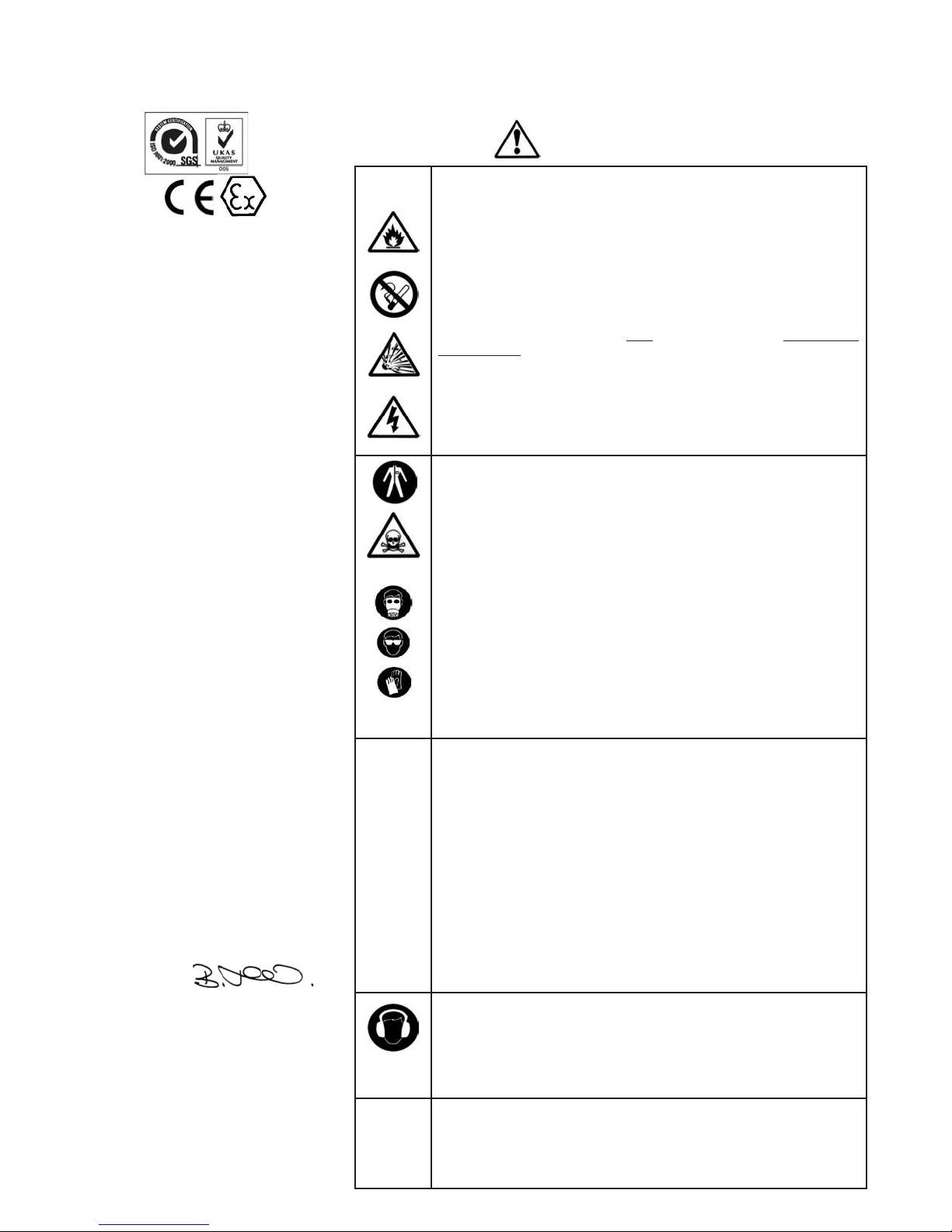
SAFETY WARNINGS
FIRE AND EXPLOSION
Solvents and coating materials can be highly flammable or
combustible when sprayed. ALWAYS refer to the coating material
suppliers instructions and COSHH sheets before using this equipment.
Users must comply with all local and national codes of practice and
insurance company requirements governing ventilation, fire precautions, operation and house-keeping of working areas.
This equipment, as supplied, is NOT
Hydrocarbons.
Static Electricity can be generated by fluid and/or air passing through
hoses, by the spraying process and by cleaning non- conductive parts
with cloths. To prevent ignition sources from static discharges, earth
continuity must be maintained to the spraygun and other metallic
equipment used. It is essential to use conductive air and/or fluid hoses.
PERSONAL PROTECTIVE EQUIPMENT
Toxic vapors – When sprayed, certain materials may be poisonous,
create irritation or be otherwise harmful to health. Always read all
labels and safety data sheets for the material before spraying and
follow any recommendations. If In Doubt, Contact Your Material
Supplier.
The use of respiratory protective equipment is recommended at all
times. The type of equipment must be compatible with the material
being sprayed.
Always wear eye protection when spraying or cleaning the spraygun
suitable for use with Halogenated
EC DECLARATION OF CONFORMITY
We: ITW Finishing UK, Ringwood Rd,
Bournemouth, Dorset, BH11 9LH, UK, as
the manufacturer of the Spraygun model
CVi, declare, under our sole responsi-
bility, that the equipment to which this
document relates is in conformity with
the following standards or other normative documents:
BS EN 292-1 PARTS 1 & 2: 1991, BS EN
1953: 1999; and thereby conform to the
protection requirements of Council
Directive 98/37/EC relating to Machinery
Safety Directive, and; EN 13463-1:2001,
council Directive 94/9/EC relating to
Equipment and Protective Systems
intended for use in Potentially Explosive
Atmospheres protection level II 2 G X.
B. Holt, General Manager
30th June 2003
DeVilbiss Automotive Refinishing reserves
the right to modify equipment specification without prior notice.
Gloves must be worn when spraying or cleaning the equipment.
Training – Personnel should be given adequate training in the safe use
of spraying equipment.
MISUSE
Never aim a spraygun at any part of the body.
Never exceed the max. recommended safe working pressure for the
equipment.
The fitting of non-recommended or non-original spares may create
hazards.
Before cleaning or maintenance, all pressure must be isolated and
relieved from the equipment.
The product should be cleaned using a gun washing machine.
However, this equipment should not be left inside gun washing
machines for prolonged periods of time.
NOISE LEVELS
The A-weighted sound level of sprayguns may exceed 85 dB (A)
depending on the set-up being used. Details of actual noise levels are
available on request. It is recommended that ear protection is worn at
all times when spraying.
OPERATING
Spray Equipment using high pressures may be subject to recoil forces.
Under certain circumstances, such forces could result in repetitive
strain injury to the operator.
Page 4
Page 4 SB-2-658-D
atent No. 2372465 (GB)
P
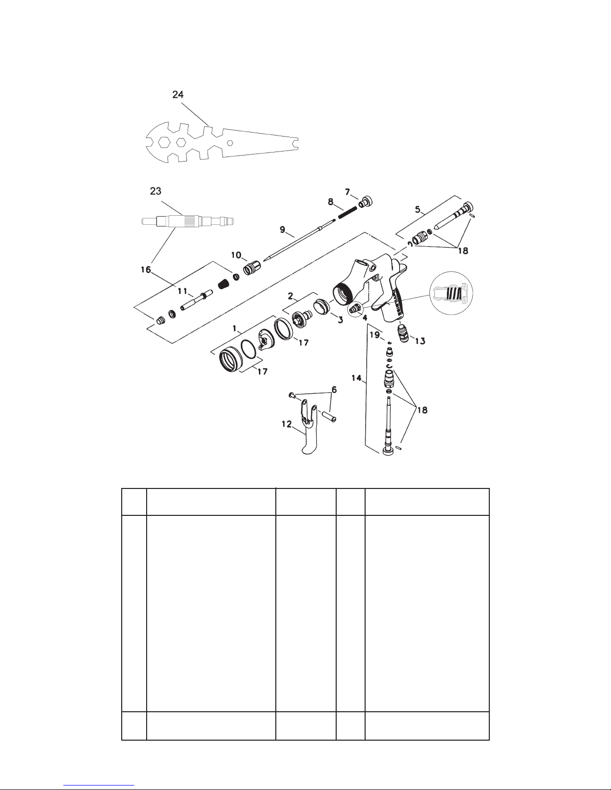
PARTS LIST
Ref.
No. Description Part Number Qty. Options
1 Air Cap/Retaining ring SP-100-***-K 1 505, 510 e.g *** = 510
2 Nozzle SP-200S-**-K 1 10, 12, 13, 14 e.g ** =13 =1.3 mm
+ 3 Separator SP-626-K5 5
+4 Packing GTI-445-K2 2
5 Spreader Valve SP-403-K 1
6 Stud and Screw GTI-408-K5 5
7 Needle Adjusting Screw SP-614-K 1
+8 Spring SP-622-K5 1
9 Needle SP-300S-**-K 1 10, 12, 13, 14 e.g ** =13 =1.3 mm
10 Airvalve housing & seal SP-612-K 1
11 Spindle 1
12 Trigger SP-617-K 1
13 Connector SP-611-K 1
14 Airflow Valve SP-402-K 1
16 Air Valve Service Kit SPK-101-K 1
17 Retaining Ring and Seals SPK-102-K 1
+18 Clip, Seal and Pin Kit GTI-428-K5 5
23 Air Valve assembly Tool 1
24 Spanner SPN-5-K 1
Spraygun Service Kit SPK-402-K 1
(parts included marked + )
Page 5
Page 5SB-2-658-D
SPECIFICATION
Air supply connection:
Universal 1/4" BSP and NPS
Maximum static Air inlet pressure:
P1= 12 bar (175 psi)
Nominal gun Air inlet pressure
with gun triggered:
1.2 bar (18 psi) 505 HVLP Air Cap
2 bar (29 psi) 510 Trans-Tech Air Cap
Maximum Service temperature: 40°C
Gun Weight: 412 g
MATERIALS OF CONSTRUCTION
Gun body: Anodized Aluminum
Nozzle: Stainless Steel
Needle: Stainless Steel
Fluid Inlet / Fluid Passages:
Anodized Aluminum & Stainless Steel
Trigger: Nickel Plated Steel
INSTALLATION
Important: To ensure that this
equipment reaches you in first
class condition, protective
coatings have been used. Flush
the equipment through with a
suitable solvent before use.
1. Attach air hose to connector (13).
Recommended hose size 8 mm
bore. The hose must be conductive
and electrical bond from the
spraygun to earth should be checked
with an ohmeter. A resistance of less
than 106Ohms is recommended.
2. Air supply should be filtered and
regulated.
3. Attach cup assembly by screwing
into the Fluid Inlet of the spraygun.
Tighten with a wrench.
OPERATION
1. Mix coating material to manufacturers instructions.
2. Fill the cup with the required amount
of material. Fill to no more than
25mm (1") from the top of the cup.
DO NOT OVERFILL.
3. Attach cup lid.
4. Turn needle adjusting screw (7)
clockwise to prevent movement.
5. Turn spreader valve (5) counterclockwise to fully open.
6. Adjust inlet air pressure (For recommended figures see Specifications)
at the gun inlet with the gun triggered. (pressure gauge attachment
shown under Accessories is recommended for this).
7. Turn needle adjusting screw counter
clockwise until first thread shows.
8. Test spray. If the finish is too dry
reduce airflow by reducing air inlet
pressure or by the Airflow Valve
(14). Screw the Adjusting Knob (14)
in to reduce pressure.
9. If finish is too wet reduce fluid flow
by turning needle adjusting screw
(7) clockwise. If atomization is too
coarse, increase inlet air pressure. If
too fine reduce inlet pressure.
10. The pattern size can be reduced by
turning spreader valve (5) clockwise.
11. Hold gun perpendicular to surface
being sprayed. Arcing or tilting may
result in uneven coating.
12. The recommended spray distance is
150-200 mm (6"-8").
13. Spray edges first. Overlap each
stroke a minimum of 50%. Move gun
at a constant speed.
14. Always turn off air supply and
relieve pressure when gun is not in
use.
PREVENTATIVE MAINTENANCE
1. Turn off air and relieve pressure in
the supply lines, or if using QD
system, disconnect from airline.
2. Remove cup lid and empty coating
material into a suitable container.
Clean the gun and cup, preferably in
a gun wash machine. Clean the cup.
3. Check the breather hole in the Lid
and the drip check lid is not blocked.
4. Remove air cap (1) and clean. If any
of the holes in the cap are blocked
with coating material use a toothpick
to clean. Never use metal wire which
could damage the cap and produce
distorted spray patterns
5. Ensure the tip of the nozzle (2) is
clean and free from damage. Build
up of dried paint can distort the
spray pattern.
6. Lubrication – stud/screw (6), needle
(9) and air valve (11) should be oiled
each day with gun oil.
REPLACEMENT OF PARTS
Nozzle (2) and Needle (9) – Remove parts
in the following order: 7, 8, 9, 1 and 2.
Replace any worn or damaged parts and
re-assemble in reverse order.
Recommended tightening torque for
nozzle (2) 9.5-12 Nm (80-100 lbf in).
Packing – Remove parts 7, 8, 9. Unscrew
cartridge (4). Fit new cartridge finger
tight. Re-assemble parts 9, 8, and 7 and
tighten cartridge (4) with spanner sufficient to seal but to allow free movement
of needle. Lubricate with gun oil.
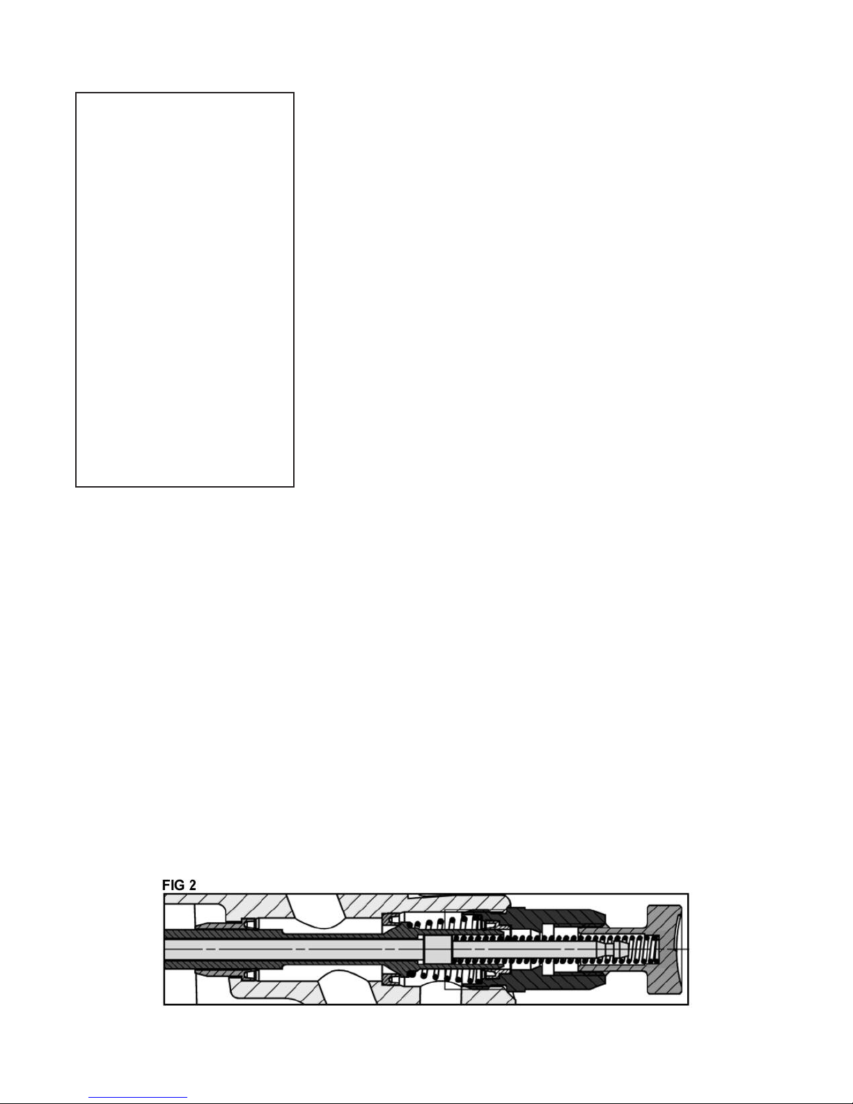
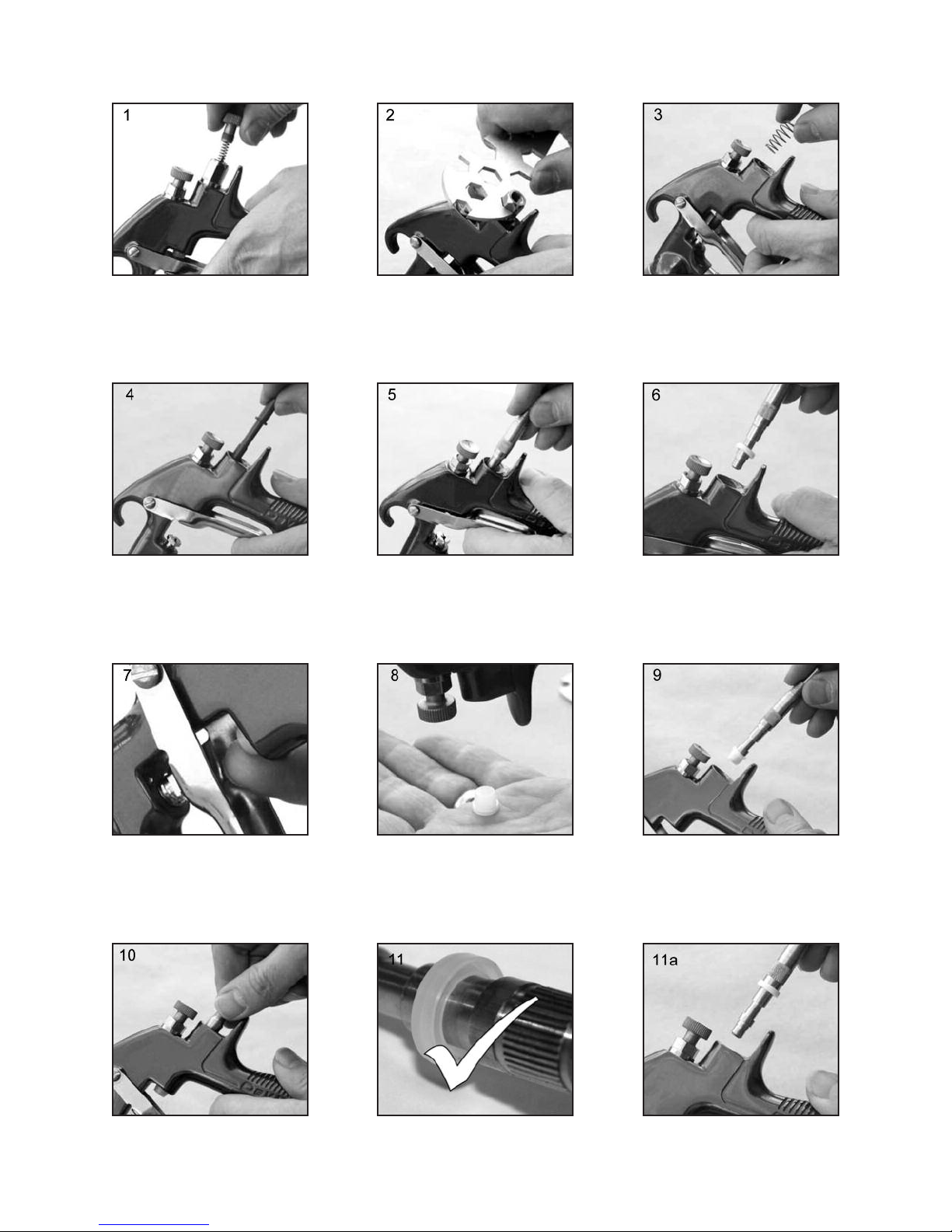
Air Valve Seal Kit (16) – (Refer to photos
1 to 21 and fig 2)
Spreader valve (5) – Caution: always
ensure that the valve is in the fully open
position by turning screw fully counterclockwise before fitting to body.
Page 6
Page 6 SB-2-658-D
1. Remove Adjusting Knob (7),
Spring (8), and Needle (9).
4. Remove Valve (11). 5. Using Service Tool SPN-7,
2. Loosen Housing (10). 3. Remove Housing (10) and
engage groove behind the
Valve Seat.
Airvalve Spring.
6. Remove Valve Seat.
7. Push out the Front Airvalve
Seal with a finger.
10. Fit new Seal to gunbody and
press firmly to ensure Seal is
engaged.
8. Turn the Gun upside down
and let the Seal fall out.
11. Fit New Valve Seat to
Service Tool so that the
groove faces the handle end
of tool.
9. Fit New Front Seal to Service
Tool so that the groove faces
the handle end of tool.
Page 7
Page 7SB-2-658-D
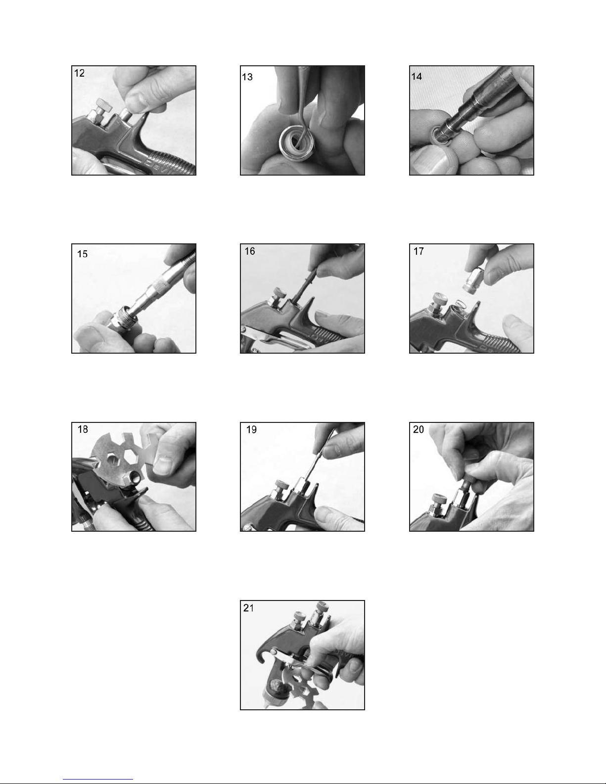
12. Fit Valve Seat to Gunbody. 13. Remove Rear Airvalve Seal
from housing (10) with a
hooked instrument.
15. Fit Seal to Housing (10). 16. Replace Valve (11). 17. Replace Valve Spring by
14. Fit new Rear Seal to Service
Tool so that the groove faces
the handle end of tool.
inserting small end of spring
into gun, and screw in
Housing (10).
18. Tighten Housing. 19. Fit Needle (9). 20. Fit Spring (8) and Knob (7).
21. Adjust Needle Packing (4)
with Spanner sufficient to
seal but to allow free movement of needle. Lubricate
with gun oil.
Page 8
Page 8 SB-2-658-D
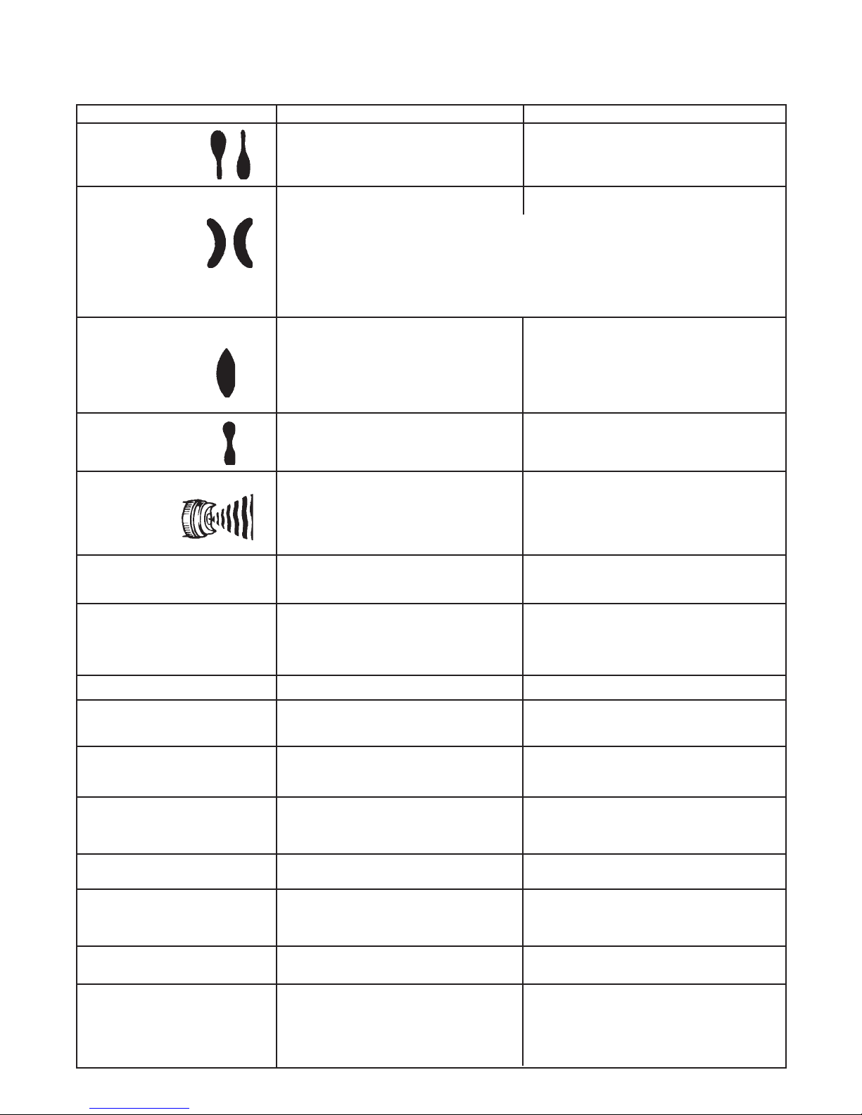
TROUBLESHOOTING
Heavy top or
bottom pattern
Heavy right or left
side pattern
Heavy center pattern
Split spray pattern
Jerky or fluttering spray
Unable to get round spray
Will not spray
Paint bubbles in cup
Fluid leaking or dripping from
cup lid
Starved spray pattern
Excessive overspray
Excessive fog
Dry spray
Fluid leaking from packing nut
Fluid leaking or dripping from
front of gun
*Most common problem.
Horn holes plugged.
Obstruction on top or bottom of fluid tip.
Cap and/or tip seat dirty.
Left or right side horn holes plugged.
Dirt on left or right side of fluid tip.
Remedies for the top-heavy, bottom-heavy, right-heavy, and left-heavy patterns:
1. Determine if the obstruction is on the air cap or the fluid tip. Do this by making a test
2. If the defect is not inverted, it is on the fluid tip. Check for a fine burr on the edge of the
3. Check for dried paint just inside the opening; remove by washing with solvent.
Fluid flow too high for atomization air.
Material flow exceeds air cap's capacity.
Spreader adjustment valve set too low.
Atomizing pressure too low.
Material too thick.
Atomization air pressure too high.
Fluid flow too low.
Spreader adjusting valve set too high.
*Loose or damaged fluid tip/seat.
Baffle seal installed incorrectly.
Material level too low.
Container tipped too far.
Obstruction in fluid passage.
Dry or loose fluid needle packing nut.
Spreader adjustment screw not seating
properly.
Air cap retaining ring loose.
No air pressure at gun.
Fluid needle adjusting screw not open
enough.
Fluid too heavy for gravity feed.
Fluid tip not tight.
Cup lid loose.
Dirty threads on cup or lid.
Cracked cup or lid.
Inadequate material flow.
Low atomization air pressure.
Too much atomization air pressure.
Gun too far from work surface.
Improper stroking (arcing, gun motion too
fast).
Too much or too fast-drying thinner.
Too much atomization air pressure.
Air pressure too high.
Gun tip too far from work surface.
Gun motion too fast.
Gun out of adjustment.
Packing nut loose.
Packing worn or dry.
Packing nut too tight.
Dry packing.
Fluid tip or needle worn or damaged.
Foreign matter in tip.
Fluid needle spring broken.
Wrong size needle or tip.
Clean. Ream with non-metallic point.
Clean.
Clean.
Clean. Ream with non-metallic point.
Clean.
spray pattern. Then, rotate the cap one-half turn and spray another pattern. If the defect
is inverted, obstruction is on the air cap. Clean the air cap as previously instructed.
fluid tip. Remove with #600 wet or dry sand paper.
Balance air pressure and fluid flow. Increase
spray pattern width with spreader adjustment
valve.
Thin or lower fluid flow.
Adjust.
Increase pressure.
Thin to proper consistency.
Reduce at transformer or gun.
Increase fluid flow (increases gun handling
speed).
Adjust.
Tighten or replace.
Install per directions.
Refill.
Hold more upright.
Backflush with solvent.
Lubricate or tighten.
Clean or replace.
Tighten.
Check air supply and air lines, blow out gun
air passages.
Open fluid needle adjusting screw.
Thin material and/or change to larger tip size.
Tighten tip to 9.5-12 Nm (80-100 lbf in.)
Push in or tighten lid.
Clean.
Replace cup and lid.
Back fluid adjusting screw out to first thread,
or change to larger tip size.
Increase air pressure and rebalance gun.
Reduce pressure.
Adjust to proper distance.
Move at moderate pace, parallel to work
surface.
Remix properly.
Reduce pressure.
Reduce air pressure.
Adjust to proper distance.
Slow down.
Adjust.
Tighten, do not bind needle.
Replace or lubricate.
Adjust.
Lubricate.
Replace tip and needle.
Clean.
Replace.
Replace.
Page 9

TROUBLESHOOTING (continued)
Page 9SB-2-658-D
Fluid dripping or leaking from
bottom of cup
Runs and sags
Thin, sandy coarse finish drying
before it flows out
Thick, dimpled finish "orange peel"
Cup loose on gun.
Cup gasket worn or missing below cup.
Cup threads dirty.
Too much material flow.
Material too thin.
Gun tilted on an angle, or gun
motion too slow.
Gun too far from surface.
Too much air pressure.
Improper thinner being used.
Gun too close to surface.
Air pressure too low.
Improper thinner being used.
Material not properly mixed.
Surface rough, oily, dirty.
Tighten.
Replace cup gasket.
Clean.
Adjust gun or reduce fluid flow.
Mix properly or apply light coats.
Hold gun at right angle to work and
adapt to proper gun technique.
Check distance. Normally approx. 8".
Reduce air pressure and check spray pattern.
Follow paint manufacturer's mixing instrs.
Check distance. Normally approx. 8".
Too much material coarsely atomized.
Increase air pressure or reduce fluid flow.
Follow paint manufacturer's mixing instrs.
Properly clean and prepare.
Page 10

Páge 10 SB-2-658-D
ACCESSORIES
GFC-501 (Acetal) 20 Oz. Cup
GFC-502 (Aluminum) 1-Liter Cup
Gravity Feed Cups
hese gravity feed cups
T
re designed to be used
a
with EXL, FLG, GFG,
GFHV, GTI or CVi gravity
eed spray guns.
f
KK-5033-505
Air Cap Test Kit
The purpose of this test
it is to measure air cap
k
atomizing air pressure at
he center air port of the
t
air cap. Used to confirm
code compliance and as
daily quality control
a
measure.
Spray Gun Lube
SSL-10-K12 (2 oz. bottle)
HAV-500 OR
HAV-501
Adjusting Valve
(HAV-501 SHOWN)
AV-500 does not
H
have pressure gauge.
Use to control air
sage at gun.
u
192219
Gun Holder
Gun holder made
o hold guns with
t
gravity cups.
HAF-507
Whirlwind™
In-Line Air Filter
Removes water, oil,
nd debris from the
a
air line.
GI-501-PSI
D
Digital
Pressure Gauge
Digital pressure
gauge for precise
ressure control at
p
the gun.
GH-505
Gun Holder
92218 Scrubs
1
and Cleaner Towels
H
®
crubs
S
moistened hand cleaner
owel for painters, body
t
men and mechanics that
o where you go and no
g
water is needed.
®
re a pre-
a
GH-407
Gun Holder
Compatible with all paint materials;
ontains no silicone or petroleum
c
distillates to contaminate paint.
MSDS Sheetavailable uponrequest.
192212
Professional Spray Gun Cleaning Kit
Contains six precision tools designed
to effectively clean
all DeVilbiss, Binks,
Finishline and other
brand spray guns.
SPN-5 Wrench
ontains all neces-
C
sary tip, hose and
nut sizes used on or
with gun.
OMX-70-K48 Paint Cup Liner Kit
Allows quick & easy clean-up.
Consists of : 1 - Piercing Tool,
48 - Disposable Liners, 48 - Drain Bushings
Automotive Refinish Quick Connects
For HVLP Guns (Air)
HC-4419 Stem
1/4" NPT(F)
HC-4719 Coupler
1/4" NPT(M) /NPS(M)
1) Wall mount bracket
un holders are
G
made to hold
standard paint cups,
gravity feed guns and
cups, and paint filters.
(
included with GH-407.
Holds standard paint
cups,gravity feedgunsand
cups, and paint filters.
Paint Spray Respirators
MSP-523 (Sm) MSP-524 (Med) MSP-525 (Lg)
NIOSH-Certified for respiratory protection in
atmospheres not immediately dangerous to life.
High Flow Type.
HC-1166 Stem
1/4" NPT(M)
HC-4720 Coupler
1/4" NPT(F)
Page 11

IMPORTANTE: Lea y siga todas las
instrucciones y Precauciones de Seguridad
antes de utilizar este equipo.
DESCRIPCIÓN
El Kit de Pistola Pulverizadora Ligero por
Gravedad CVi cumple las normas ATEX
94/9/CE, nivel de protección; II 2 G X,
Adecuado para el uso en las Zonas 1 y 2.
Al usar el casquillo de aire #505, este
diseño utiliza tecnología (HVLP) de atomización que cumple con las especificaciones de EPA para reducir el exceso de
atomización y mejorar la eficacia del
recubrimiento. Esta pistola produce una
presión de casquillo de aire de aproximadamente 10 psi a una presión de
entrada de la pistola de 18 psi (cumple
con normas emitidas por SCAQMD y
otras autoridades de la calidad del aire).
IMPORTANTE: Estas Pistolas pulverizadoras son apropiadas para el uso con
materiales de recubrimiento a base de
agua o de disolventes. El diseño utiliza
tecnología de pulverización HVLP para
reducir la sobrepulverización y mejorar la
eficacia del recubrimiento. Si tiene
alguna duda respecto a la idoneidad de
un material específico, póngase en
contacto con su Distribuidor local o directamente con ITWIF.
DECLARACIÓN DE CONFORMIDAD CE
Nosotros: ITW Finishing UK, de
Ringwood Rd, Bournemouth, Dorset,
BH11 9LH, Reino Unido, como fabricantes
de la Pistola pulverizadora modelo CVi,
declaramos bajo nuestra exclusiva
responsabilidad que el equipo al que se
refiere este documento cumple los siguientes estándares o normas:
BS EN 292-1 PARTES 1 y 2: 1991, BS EN
1953:1999; y que por tanto cumple los
requisitos de protección de la Directiva del
Consejo 98/37/CE relativa a la Directiva
sobre Seguridad de las Máquinas y EN
13463-1:2001, Directiva del Consejo
94/9/CE relativa a Equipos y sistemas de
protección diseñados para ser utilizados
en atmósferas potencialmente explosivas
nivel de protección II 2 G X.
Página 11SB-2-658-D
ADVERTENCIAS DE SEGURIDAD
INCENDIO Y EXPLOSIÓN
Los disolventes y los materiales de recubrimiento pueden ser altamente inflamables o combustibles al pulverizarse. Consulte SIEMPRE
abricante del material de recubrimiento y las hojas COSHH antes de utilizar
f
ste equipo.
e
Los usuarios deben cumplir la normativa nacional y local y los requisitos de las
ompañías de seguros respecto a ventilación, precauciones contraincendios,
c
peración y mantenimiento de las zonas de trabajo.
o
Este equipo, tal y como se suministra, NO
idrocarburos Halogenados
H
a Electricidad Estática puede ser generada por el paso de fluido y/o aire por los
L
manguitos, por el proceso de pulverización y por la limpieza de piezas no
conductoras con paños. Para impedir que las descargas estáticas produzcan
uentes de ignición, debe mantenerse la continuidad de tierra a la pistola pulver-
f
izadora y a otros equipos metálicos utilizados. Es imprescindible utilizar
manguitos de aire y/o fluido que sean conductores de electricidad.
.
es adecuado para su uso con
EQUIPO DE PROTECCIÓN PERSONAL
Vapores tóxicos - Al pulverizarse, ciertos materiales pueden ser tóxicos, crear
rritación o ser dañinos para la salud de otra forma. Lea siempre todas las
i
etiquetas y hojas de datos de seguridad del material antes de pulverizar, y siga
cualquier recomendación. En caso de Duda, Póngase en Contacto con el
Proveedor del Material.
Se recomienda el uso de equipos de protección respiratoria en todo momento. El
tipo de equipo debe ser compatible con el material que se está pulverizando.
Lleve siempre protección ocular al pulverizar o al limpiar la pistola.
Deben llevarse guantes al pulverizar o al limpiar la pistola.
Formación - El personal debe recibir una formación adecuada en el uso seguro
de equipos de pulverización.
MAL USO
No apunte nunca con una pistola de pulverización a ninguna parte del cuerpo.
No supere nunca la presión máxima de operación segura recomendada del
equipo.
El acoplamiento de piezas de repuesto no recomendadas o no originales puede
crear riesgos.
Antes de realizar limpieza o mantenimiento, toda presión debe aislarse y aliviarse
en el equipo.
El producto debe ser limpiado usando una máquina para lavar pistolas. No
obstante, este equipo no debe dejarse dentro de una máquina de lavar pistolas
durante periodos de tiempo prolongados.
NIVELES SONOROS
El nivel sonoro con ponderación A de las pistolas de pulverización puede superar
los 85 dB(A) dependiendo de la configuración utilizada. Los detalles de niveles
sonoros reales están disponbles previa petición. Se recomienda llevar protección
acústica en todo momento durante la pulverización.
las instrucciones del
B. Holt, Director General
30/6/2003
DeVilbiss Automotive Refinishing se
reserva el derecho a modificar las especificaciones del equipo sin previo aviso.
OPERACIÓN
Los Equipos de Pulverización que funcionan a alta presión pueden verse
sometidos a fuerzas de retroceso. Bajo determinadas circunstancias, dichas
fuerzas podrían provocar al operador lesiones por esfuerzo repetitivo (RSI).
Page 12

Página 12 SB-2-658-D
Patente Nº 2372465 (GB)
LISTA DE PIEZAS
Nº Número
Ref. Descriptión de Pieza Cant Opciones
1 Casquillo de aire / Anillo de retención SP-100-***-K 1 505, 510 ej. *** = 510
2 Pico de fluido SP-200S-**-K 1 10, 12, 13, 14 ej. ** =13 =1.3 mm
+ 3 Separador SP-626-K5 5
+4 Empaquetadura GTI-445-K2 2
5 Válvula dispersora SP-403-K 1
6 Espiga y tornillo GTI-408-K5 5
7 Tornillo de ajuste de la aguja SP-614-K 1
+8 Muelle SP-622-K5 1
9 Aguja SP-300S-**-K 1 10, 12, 13, 14 ej. ** =13 =1.3 mm
10 Alojamiento de la válvula de aire SP-612-K 1
& junta
11 Vástago 1
12 Gatillo SP-617-K 1
13 Conector SP-611-K 1
14 Válvula de caudal de aire SP-402-K 1
16 Kit de mantenimiento de la SPK-101-K 1
válvula de aire
17 Retén y juntas SPK-102-K 1
+18 Kit de clip, junta y perno GTI-428-K5 5
23 Herramienta para el conjunto de
la válvula de aire 1
24 Llave SPN-5-K 1
Kit de Mantenimiento de SPK-402-K 1
la Pistola Pulverizadora
(piezas incluidas marcadas con + )
Page 13

Página 13SB-2-658-D
ESPECIFICACIÓN
Conexión del suministro de aire :
Universal 1/4" BSP and NPS
Presión nominal de entrada de aire
en la pistola – con el gatillo apretado:
1.2 bar (18 psi) casquillo de aire 505 HVLP
2 bar (29 psi) casquillo de aire 510 Trans-Tech
Temperatura Máxima de uso: 40°C
Peso de pistola: 412 g
MATERIALES DE CONSTRUCCIÓN
Cuerpo de la pistola: Aluminio
anodizado
Boquilla: Acero inoxidable
Aguja: Acero inoxidable
Entrada de fluido / Conductos de fluido:
Aluminio anodizado y acero inoxidable
Gatillo: Acero niquelado
INSTALACIÓN
Importante: Para asegurarse
de que este equipo llega a
usted en condiciones óptimas,
se han utilizado recubrimientos
protectores. Enjuague el
equipo con un disolvente
adecuado antes de su uso.
1. Acople el manguito de aire al
conector (13). Tamaño de manguito
recomendado: 8 mm diám. interior.
El manguito debe ser conductor de
electricidad y la conexión eléctrica
entre la pistola pulverizadora y tierra
debe verificarse con un ohmímetro.
Se recomienda una resistencia de
menos de 106Ω. El suministro de aire
debe estar filtrado y regulado.
2. El suministro de aire debe estar
filtrado y regulado.
3. Acople el conjunto de la cubeta
enroscándolo en la entrada de fluido
de la pistola pulverizadora. Apriete
cuando haya entrado del todo.
OPERACIÓN
1. Mezcle el material de recubrimiento
siguiendo las instrucciones del fabricante.
2. Llene la copa con la cantidad
requerida de material. No llene a
menos de 25 mm de la parte superior de la copa. NO LLENE
DEMASIADO.
3. Acople la tapa de la cubeta.
4. Gire el tornillo de ajuste de la aguja
(7) en el sentido de las agujas del
reloj para impedir que se mueva.
5. Gire la válvula de dispersión (5) en el
sentido contrario a las agujas del
reloj hasta que esté abierta del todo.
6. Ajuste la presión de aire de entrada
(ver valores recomendados en las
Especificaciones) en la entrada de la
pistola con el gatillo apretado. con el
gatillo apretado (se recomienda
utilizar para ello el manómetro
mostrado en Accesorios).
7. Gire el tornillo de ajuste de la aguja
en el sentido contrario a las agujas
del reloj hasta que se vea la primera
rosca.
8. Haga una prueba de pulverización.
Si el acabado es demasiado seco,
reduzca el caudal de aire reduciendo
la presión de entrada de aire o mediante la Válvula de Caudal de Aire
(14). Gire el Pomo de Ajuste (14)
hacia dentro para reducir la presión.
9. Si el acabado es demasiado
húmedo, reduzca el caudal de fluido
girando el tornillo de ajuste de la
aguja (7) en el sentido de las agujas
del reloj o reduciendo la presión del
fluido. Si la atomización es
demasiado gruesa, aumente la
presión de entrada de aire. Si es
demasiado fina, reduzca la presión
de entrada.
10. El tamaño del patrón puede
reducirse ajustando la válvula
dispersora (5) en el sentido de las
agujas del reloj.
11. Sujete la pistola perpendicular a la
superficie a pulverizar. Pulverizar en
arcos o con la pistola inclinada
puede producir un recubrimiento
desigual.
12. La distancia de pulverización
recomendada es de 150 - 200 mm.
13. Pulverice primero los bordes.
Solape cada pasada el 50% como
mínimo. Mueva la pistola a una
velocidad constante.
14. Cierre siempre el suministro de aire
y alivie la presión cuando la pistola
no se esté utilizando.
MANTENIMIENTO PREVENTIVO
1. Cierre el suministro de aire y alivie la
presión en los manguitos de suministro, o si utiliza el sistema QD,
desconéctelo del manguito de aire.
2. Retire la tapa de la cubeta y vacíe el
material de recubrimiento en un
recipiente apropiado. Limpie la
pistola y la cubeta, preferentemente
en una máquina de lavado de
pistolas. Limpie la cubeta.
3. Compruebe que el orificio de ventilación de la tapa y de la tapa antigoteo no está obstruido.
4. Retire el casquillo de aire (1) y
límpielo. Si alguno de los orificios
del casquillo está obstruido con
material de recubrimiento, utilice un
palillo de dientes para limpiarlo. No
utilice nunca un alambre metálico,
porque podría dañar el casquillo y
producir patrones de pulverización
distorsionados.
5. Asegúrese de que la punta de la
boquilla (2) está limpia y libre de
desperfectos. Una acumulación de
pintura seca puede distorsionar el
patrón de pulverización.
6. Lubricación – la espiga/tornillo (6), la
aguja (9) y la válvula de aire (11)
deben lubricarse con aceite cada dia
con aceite del pistola.
SUSTITUCIÓN DE PIEZAS
Boquilla (2) y Aguja (9) – Retire las piezas
en el siguiente orden: 7, 8, 9, 1 y 2.
Sustituya cualquier pieza desgastada o
dañada y vuelva a montar las piezas en
orden inverso. Par de apriete recomendado para la boquilla (2) 9,5-12 Nm (80100 pies-libra/pulgada).
Guarnición – Retire las piezas 7, 8, 9.
Desenrosque el cartucho (4). Coloque un
cartucho nuevo y apriete con los dedos
solamente. Vuelva a montar las piezas 9,
8 y 7 y apriete el cartucho (4) con una
llave, lo suficiente para hacer sello pero
dejando que la aguja se desplace libremente. Lubrique con aceite para pistolas.
Kit de Junta de la Válvula de Aire (16) –
(Ver FIG 2 y fotos 1 a 21).
Válvula Dispersora (5) – Precaución:
asegúrese siempre de que la válvula está
en posición completamente abierta
girando el tornillo en el sentido contrario
a las agujas del reloj hasta que haga tope
antes de instalarla en el cuerpo de la
pistola.
Page 14

Página 14 SB-2-658-D
1. Retire el pomo de ajuste (7),
el muelle (8), y la aguja (9).
4. Retire la válvula (11). 5. Usando la herramienta de
2. Afloje el alojamiento (10). 3. Retire el alojamiento (10) y
manteni-miento SPN-7,
enganche la muesca detrás
del asiento de la válvula.
el muelle de la válvula de
aire.
6. Retire el asiento de la
válvula.
7. Haga salir la junta delantera
de la válvula de aire empujando con el dedo.
10. Coloque la junta nueva sobre el
cuerpo de la pistola y empuje
firmemente para asegurarse de
que la junta quede correctamente colocada.
8. Ponga la pistola boca abajo
y deje que se caiga la junta.
11. Instale el asiento de la
válvula nuevo en la
herramienta de mantenimiento de manera que la
muesca quede orientada
hacia el extremo con mango
de la herramienta.
9. Instale una junta delantera
nueva en la herramienta de
mantenimiento de manera
que la muesca quede orientada hacia el extremo con
mango de la herramienta.
Page 15

Página 15SB-2-658-D
12. Coloque el asiento de
válvula en el cuerpo de la
pistola.
15. Coloque la junta en el
alojamiento (10).
13. Retire la junta de la válvula
de aire del alojamiento (10)
con un instrumento que
tenga gancho.
16. Vuelva a colocar el husillo
(11).
14. Instale una junta trasera
nueva en la herramienta de
mantenimiento de manera
que la muesca quede orientada hacia el extremo con
mango de la herramienta.
17. Vuelva a colocar el muelle
de la válvula insertando el
extremo pequeño del muelle
en la pistola, y el tornillo en
el alojamiento (10).
18. Apriete el alojamiento. 19. Coloque la aguja (9). 20. Instale el muelle (8) y el
pomo (7).
21. Ajuste la guarnición de la aguja (4) con
una llave lo suficiente para hacer sello
pero permitiendo que se desplace la
aguja. Lubrique con aceite para pistolas.
Page 16

Página 16 SB-2-658-D
LOCALIZACIÓN Y REPARACIÓN DE PROBLEMAS
CONDICIÓN CAUSA CORRECCIÓN
Patrón pesado en
a parte superior
l
o inferior
atrón pesado en
P
el lado derecho
izquierdo
o
Patrón pesado
n el centro
e
atrón de pulverización
P
dividida
Pulverización entrecortada o
con vibraciones
Imposibilidad de obtener
pulverización redondeada
No pulveriza
Burbujas de pintura en la cubeta
El fluido se escapa o gotea de la tapa
de la cubeta
Patrón de pulverización subalimentada
Agujeros de la horquilla obstruidos.
bstrucción en la parte superior o inferior de la
O
punta de fluido.
asquillo y/o asiento de la punta está sucio.
C
gujeros en el lado izquierdo o derecho de la
A
orquilla obstruidos.
h
uciedad en el lado izquierdo o derecho de la
S
unta del líquido.
p
orrección de los patrones pesados en la parte superior, inferior, el lado derecho e izquierdo.
C
. Determine si la obstrucción está en el casquillo de aire o en la punta de fluido. Realice esto haciendo
1
na prueba del patrón de pulverización. Luego gire el casquillo media vuelta y pulverice con otro
u
atrón. Si se invierte el defecto, la obstrucción se encuentra en el casquillo de aire. Limpie el
p
asquillo de aire siguiendo las instrucciones previas.
c
i el defecto no se invierte, la obstrucción se encuentra en la punta de fluido. Verifique si hay una
S
.
2
equeña protuberancia en el borde de la punta de fluido. Quítela con papel de lija #600 húmedo o seco.
p
. Verifique si hay pintura seca dentro de la abertura; elimínela lavándola con disolvente.
3
El fluido fluye demasiado alto para el aire de
tomización.
a
l flujo del material sobrepasa la capacidad del
E
casquillo de aire.
l ajuste de la válvula dispersora es muy bajo.
E
La presión de atomización es muy baja.
l material es muy espeso.
E
a presión de aire de atomización es muy alta.
L
El fluido fluye muy bajo.
l ajuste de la válvula dispersora es muy alto.
E
La punta/el asiento del fluido está flojo o dañado.
*
La junta deflectora fue instalada incorrectamente.
El nivel del material es muy bajo.
El recipiente se inclinó mucho.
Obstrucción en el conducto del fluido.
La tuerca de la empaquetadura de la aguja de
fluido seca o floja.
El tornillo de ajuste del dispersador no está
alojado debidamente.
El anillo de retención del casquillo de aire está flojo.
No hay presión de aire en la pistola.
El tornillo de ajuste de la aguja de fluido no está
lo suficientemente abierto.
El fluido es muy pesado para la alimentación
por gravedad.
La punta de fluido no está apretada.
La tapa de la cubeta está floja.
Roscas sucias en la cubeta o tapa.
Cubeta o tapa agrietada.
Flujo inadecuado del material.
Presión de aire de atomización baja.
impie. Escariar con punta no metálica.
L
Limpie.
impie.
L
impie. Escariar con punta no metálica.
L
Limpie.
quilibre la presión de aire y el flujo de fluido.
E
Aumente el ancho del patrón de pulverización con la
válvula de ajuste del dispersador.
iluya o baje el flujo de fluido.
D
Ajuste.
umente la presión.
A
iluya hasta lograr la consistencia adecuada.
D
eduzca la presión en el transformador o en la pistola.
R
Aumente el flujo de líquido (aumente la velocidad de
anipulación de la pistola).
m
Ajuste.
Apriete o reemplace.
Instálelo de acuerdo con las instrucciones.
Vuelva a llenar.
Sosténgalo de forma más vertical.
Limpie con disolvente.
Lubrique o apriete.
Limpie o reemplace.
Apriete.
Verifique el suministro de aire y las líneas de aire,
limpie con aire comprimido los conductos de aire de
la pistola.
Abra el tornillo de ajuste de la aguja de fluido.
Diluya el material y/o cambie la punta por una más
grande.
Apriete la punta a 9.5-12 Nm (80-100 lbf in.)
Empuje o apriete la tapa.
Limpie.
Reemplace la cubeta o la tapa.
Retuerza el tornillo de ajuste de fluido hasta la
primera rosca o cambie la punta por una más grande.
Aumente la presión de aire y reequilibre la pistola.
Sobrepulverización excesiva
Nebulización excesiva
Pulverización seca
Escape de fluido por la tuerca de la
empaquetadura
Escape o goteo de fluido por la parte
delantera de la pistola
Demasiada presión de aire de atomización.
La pistola está muy alejada de la superficie de trabajo.
Carrera indebida (formación de arco, el desplazamiento de la pistola es muy rápido).
Demasiado diluyente o diluyente de secado
muy rápido.
Demasiada presión de aire de atomización.
Presión de aire muy alta.
Punta de pistola muy alejada de superficie de trabajo.
El desplazamiento de la pistola es muy rápido.
Pistola desajustada.
Tuerca de la empaquetadura floja.
Empaquetadura gastada o seca.
Tuerca de la empaquetadura muy apretada.
Empaquetadura seca.
Punta de fluido o aguja gastada o dañada.
Materias foráneas en la punta.
Muelle de la aguja del fluido roto.
Aguja o punta de tamaño inadecuado.
*Problemas más comunes.
Reduzca la presión.
Ajuste hasta la distancia adecuada.
Desplace la pistola a un ritmo moderado, paralelo a
la superficie de trabajo.
Vuelva a mezclar el diluyente debidamente.
Reduzca la presión.
Reduzca la presión de aire.
Ajuste hasta la distancia adecuada.
Reduzca la velocidad.
Ajuste.
Apriete, no bloquee la aguja.
Reemplace o lubrique.
Ajuste.
Lubrique.
Reemplace la punta y la aguja.
Limpie.
Reemplace.
Reemplace.
Page 17

LOCALIZACIÓN Y REPARACIÓN DE PROBLEMAS (continuará)
CONDICIÓN CAUSA CORRECCIÓN
l fluido se escapa o gotea desde la parte
E
inferior de la cubeta.
e corre
S
Acabado rugoso arenoso, fino, que se
eca antes de fluir.
s
cabado grueso, no uniforme, como el de
A
una “cáscara de naranja”.
ubeta floja en la pistola.
C
uarnición de la cubeta gastada o falta
G
ebajo de la cubeta.
d
oscas de la cubeta sucias.
R
emasiado flujo de material.
D
Material demasiado diluido.
istola inclinada en ángulo o se desplaza
P
muy despacio.
Pistola muy lejos de la superficie.
emasiada presión de aire.
D
e está empleando un diluyendo inadecuado.
S
istola muy cerca de la superficie.
P
Presión de aire muy baja.
e está empleando un diluyente inadecuado.
S
No se ha mezclado debidamente el material.
uperficie áspera, aceitosa o sucia.
S
priete.
A
Reemplace la guarnición de la cubeta.
impie.
L
juste la pistola o reduzca el flujo de fluido.
A
ezcle debidamente o aplique capas livianas.
M
Sostenga la pistola en un ángulo correcto para
rabajar y adáptela a una técnica debida.
t
Verifique la distancia. Normalmente, aprox. 8 pulg.
Reduzca la presión de aire y verifique el patrón de
pulverización.
Siga las instrucciones de mezclado del fabricantede la pintura.
erifique la distancia. Normalmente, aprox. 8 pulg.
V
emasiado material áspero fue atomizado.
D
Aumente la presión de aire o reduzca el flujo de fluido.
Siga las instrucciones de mezclado del fabricante de
a pintura.
l
Limpie y prepare debidamente.
Página 17SB-2-658-D
Page 18

Página 18 SB-2-658-D
ACCESORIOS
ubeta GFC-501 (acetal)
C
ubeta de 1 litro GFC-502 (aluminio)
C
Cubetas alimentadas por gravedad
stas cubetas alimentadas por
E
ravedad son diseñadas para
g
ser usadas con pistolas
pulverizadoras EXL, FLG,
FG, GFHV, GTI o CVi.
G
K-5033-505
K
it de prueba
K
el casquillo de aire
d
El propósito de este kit de
prueba es medir la presión de
aire de atomización del
casquillo de aire en el puerto
central de aire del casquillo de
aire. Utilizado para confirmar
el cumplimiento con el código
y como una medida diaria de
control de calidad.
ubricante de pistola pulverizadora
L
SL-10-K12 (botella de 2 oz.)
S
ompatible con todos los materiales
C
de pintura; no contiene destilados de
ilicona ni petróleo que contaminen la
s
pintura.Hoja de Datos de Seguridadde
os Materiales (MSDS, por sus siglas
l
en inglés) disponible previa solicitud.
192212
Kit de limpieza de pistola
pulverizadora profesional
Contiene seis accesorios de precisión
diseñados para
limpiar eficazmente
todas las pistolas
p u l v e r i z a d o r a s
DeVilbiss, Binks,
Finishline y de otras
marcas.
AV-500 O
H
HAV-501
álvula reguladora
V
(HAV-501-MOSTRADA)
AV-500 no tiene
H
manómetro. Se utiliza
para controlar el uso
el aire en la pistola.
d
HAF-507
Filtro de aire en
línea Whirlwind™
Elimina el agua, el
ceite y la suciedad
a
de la línea de aire.
192219
Soporte de pistola
Soporte de pistola hecho
para sostener pistolas
on cubetas alimentadas
c
por gravedad.
lave SPN-5
ontiene todo los
C
tamaños necesarios
de punta, manguito
y tuerca utilizados
en o con la pistola.
Kit de forros de cubetas de pintura OMX-70-K48
Permite la limpieza rápida y fácil
Compuesto por: 1 herramienta perforadora,
48 – forros desechables, 48 – Boquillas
de descarga.
L
Dispositivos de conexión rápida para repintado automotriz
Para pistolas de HVLP (aire)
Tipo de alto flujo.
GI-501-PSI
D
Manómetro digital
Manómetro digital
para un control
reciso de la presión
p
en la pistola.
H-505
G
Soporte de pistola
os soportes de pistola se
L
fabrican para sostener cubetas
de pintura estándares, pistolas
alimentadas por gravedad
cubetas y filtros de pintura.
Respiradores para pulverizadores de pintura
MSP-523 (pequeño) MSP-524 (mediano)
Certificados por NIOSH para protección respiratoria en atmósferas que no implican riesgo
inmediato para la vida.
MSP-525 (grande)
92218 Scrubs
1
oallas para limpiarse las manos
T
®
crubs
S
rehumedecidas para que
p
intores, encargados de
p
arrocería y mecánicos se
c
impien las manos. Van
l
onde usted vaya y no se
d
ecesita agua.
n
GH-407
oporte de pistola
S
1) Soporte de montaje
(
mural incluido con GH-407.
ostiene cubetas de
S
pintura estándares, pistolas
alimentadas por gravedad y
cubetas y filtros de pintura.
®
on toallas
s
Vástago HC-4419
1/4 pulg. NPT(F)
Acoplador HC-4719
1/4 pulg. NPT(M) /NPS(M)
Vástago HC-1166
1/4 pulg. NPT(M)
Acoplador HC-4720
1/4 pulg. NPT(F)
Page 19

IMPORTANT : Lire et respecter toutes les direc-
ives et CONSIGNES DE SÉCURITÉ avant d’utiliser
t
cet appareil.
DESCRIPTION
Cette trousse de pistolet pulvérisateur léger à
alimentation par gravité CVi est conforme aux
ormes ATEX 94/9/EC, niveau de protection : II
n
2 G X, convenant à l’utilisation en zones 1 et 2.
orsqu’on emploie l’anneau déflecteur nº 505,
L
ce modèle utilise une technologie
’atomisation à grand débit à basse pression
d
conforme aux normes de l’EPA afin de réduire
es pertes de peinture et améliorer l’efficacité
l
de couverture. Ce pistolet génère une pression
de l’anneau déflecteur de 10 psi à une pression
’aspiration de 18 psi (conformément aux
d
normes émises par SCAQMD et d’autres organ-
smes de surveillance de la qualité de l’air).
i
IMPORTANT : Ces pistolets pulvérisateurs convi-
ennent à la pulvérisation de produits de revêtement à base d’eau ou de solvant. La conception
utilise une technologie d’atomisation à grand
débit à basse pression qui réduit les pertes de
peinture et améliore l’efficacité de couverture.
En cas de doute au sujet de la compatibilité d’un
matériau en particulier, communiquer avec le
représentant local ou directement avec
DeVilbiss.
Page 19SB-2-658-D
MISES EN GARDE
NCENDIE ET EXPLOSION
I
es solvants et les matériaux de revêtement peuvent être extrêmement inflam-
L
ables ou combustibles lorsqu’ils sont vaporisés. TOUJOURS consulter les
m
directives fournies par le fabricant des matériaux de revêtement et les fiches sur
la santé et sécurité au travail avant d’utiliser cet appareil.
es utilisateurs doivent se conformer à tous les codes de bonnes pratiques
L
ocaux et nationaux et aux exigences des assureurs concernant la ventilation, la
l
révention des incendies, le fonctionnement des appareils et la propreté des
p
espaces de travail.
Cet appareil, tel que fourni, ne convient PAS
hydrocarbure halogéné.
e passage des liquides ou de l’air dans les tuyaux, le processus de vaporisation
L
t le nettoyage des pièces non conductrices à l’aide de chiffons peuvent produire
e
de l’électricité statique. Afin de prévenir la formation de sources d’allumage en
aison de l’électricité statique, le pistolet pulvérisateur et les autres appareils en
r
étal utilisés doivent être reliés à la terre en permanence. Il est essentiel
m
d’utiliser des conduits en matériaux conducteurs pour l’air et les liquides.
MATÉRIEL DE PROTECTION DES EMPLOYÉS
apeurs toxiques : lorsqu’on les vaporise, certains matériaux peuvent être
V
toxiques, créer des irritations ou nuire d’une manière ou d’une autre à la santé.
Toujours lire toutes les étiquettes et fiches signalétiques des produits avant de
les vaporiser et suivre toutes les recommandations. En cas de doute, communi-
quer avec le fournisseur de matériaux.
Il est recommandé d’utiliser un dispositif de protection du système respiratoire
en tout temps. Le type de dispositif doit être compatible avec le produit vaporisé.
Toujours porter des lunettes de protection pour vaporiser ou nettoyer ce pistolet
pulvérisateur.
à l’utilisation avec des solvants de type
DÉCLARATION DE CONFORMITÉ EC
Nous : ITW Finishing UK, Ringwood Rd,
Bournemouth (Dorset) BH11 9LH, R.-U., en tant
que fabricant du pistolet pulvérisateur de
modèle CVi , déclare, en vertu de notre seule
responsabilité, que l’appareil au sujet duquel
porte ce document est conforme aux normes
suivantes et aux autres documents normatifs :
BS EN 292-1 PARTIES 1 et 2 : 1991, BS EN
1953 : 1999; et par conséquent est conforme
aux exigences de sécurité de la directive
98/37/EC du Conseil relative à la Directive sur
la sécurité des appareils et EN 13463-1 : 2001,
de la directive 94/9/EC du Conseil relative au
matériel et systèmes de protection destinés à
une utilisation dans des conditions
d’atmosphère potentiellement explosif,
niveau de protection II 2 G X.
B. Holt, directeur général,
30 juin 2003
DeVilbiss Automotive Refinishing se réserve
le droit de modifier les caractéristiques de
l’appareil sans préavis.
Porter des gants pour vaporiser ou nettoyer cet appareil.
Formation : le personnel doit recevoir une formation adéquate touchant
l’utilisation sécuritaire du matériel de pulvérisation.
MAUVAIS USAGE
Ne jamais diriger un pistolet pulvérisateur vers une partie du corps humain.
Ne jamais dépasser les pressions maximum recommandées pour un fonctionnement sécuritaire de l’appareil.
L’installation de pièces détachées non recommandées ou non originales peut être
dangereuse.
Avant de nettoyer ou d’entretenir l’appareil, toute portion sous pression doit être
isolée de l’appareil et purgée.
Ce produit doit être nettoyé à l’aide d’une laveuse à pistolet pulvérisateur.
Cependant, cet appareil ne doit pas être laissé dans la laveuse à pulvérisateur
pendant une période prolongée.
NIVEAU SONORE
Le niveau acoustique pondéré A des pistolets pulvérisateurs peut dépasser 85 dB
(A), en fonction de l’installation utilisée. Les détails du niveau sonore sont
disponibles sur demande. Il est recommandé de porter un dispositif de protection
de l’ouïe en tout temps lors de l’utilisation du pistolet pulvérisateur.
FONCTIONNEMENT
Le matériel de pulvérisation à haute pression peut produire un effet de recul.
Dans certaines circonstances, de telles forces peuvent occasionner des microtraumatismes répétés à l’opérateur.
Page 20

Page 20 SB-2-658-D
revet nº 2372465 (GB)
B
LISTE DE PIÈCES
Nº Numéro
de ref. Description de pièce Qté Options
1 Anneau déflecteur/anneau de retenue SP-100-***-K 1 505, 510 ex. *** = 510
2 Buse SP-200S-**-K 1 10, 12, 13, 14 ex. ** =13 =1,3 mm
+ 3 Séparateur SP-626-K5 5
+ 4 Garniture d’étanchéité GTI-445-K2 2
5 Soupape de diffusion SP-403-K 1
6 Pivot et vis GTI-408-K5 5
7 Vis de réglage du pointeau SP-614-K 1
+ 8 Ressort SP-622-K5 1
9 Pointeau SP-200S-**-K 1 10, 12, 13, 14 ex. ** =13 =1,3 mm
Boîtier et joint d’étanchéité de la soupape d’air
10
11 Arbre 1
12 Gâchette SP-617-K 1
13 Connecteur SP-611-K 1
14 Soupape de débit d’air SP-402-K 1
16 Trousse d’entretien de la soupape d’air SPK-101-K 1
17 Bague d’arrêt et joints SPK-102-K 1
+18 Ensemble d’agrafe, joint et goupille GTI-428-K5 5
23 Outils de montage de soupape d’air 1
24 Tricoise SPN-5-K 1
Trousse d’entretien de pistolet pulvérisateur
(les pièces incluses sont identifiés par un +)
SP-612-K 1
SPK-402-K 1
Page 21

Page 21SB-2-658-D
ARACTÉRISTIQUES
C
accord d’orifice d’admission :
R
niversel ⁄ po BSP et NPS
u
Pression d’aspiration statique maximum :
12 bars (175 psi)
=
P
1
ression d’aspiration nominale du pistolet
P
en appuyant sur la gâchette :
,2 bar (18 psi) Anneau déflecteur 505 à grand
1
débit à basse pression
bars (29 psi) 510 Anneau déflecteur
2
Trans-Tech
Température de fonctionnement maximum :
0°C
4
Poids du pistolet : 412 g
MATÉRIAUX DE FABRICATION
Corps du pistolet :Aluminium anodisé
Buse : Acier inoxydable
ointeau : Acier inoxydable
P
rifice d’alimentation/passages du liquide :
O
Aluminium anodisé et acier inoxydable
âchette : Acier nickelé
G
INSTALLATION
Important : Afin d’assurer que ce
matériel parvienne au consommateur en parfait état, on applique un
revêtement de protection. Rincer
abondamment l’appareil dans un
solvant adéquat avant de l’utiliser.
1. Fixer le tuyau d’alimentation en air au
raccord (13). On recommande d’utiliser
un tuyau de 8 mm d’alésage. Le tuyau
doit être conducteur et la mise à la terre
du pistolet pulvérisateur doit être vérifié à
l’aide d’un ohmmètre. Une résistance
inférieure à 10
6
ohms est recommandée.
2. Le débit d’air doit être régulé et filtré.
3. Fixer le module du réservoir en le vissant
à l’orifice d’alimentation en liquide du
pistolet pulvérisateur. Resserrer à l’aide
d’une clé.
FONCTIONNEMENT
1. Suivre les directives du fabricant du produit
e revêtement concernant la dilution.
d
. Remplir le réservoir avec la quantité de
2
produit requis. Ne pas remplir le réservoir
u vaporisateur à plus de 2,5 cm (1 po)
d
du sommet. NE PAS TROP REMPLIR.
3. Fixer le couvercle du réservoir.
4. Tourner la vis de réglage du pointeau (7)
ans le sens des aiguilles d’une montre
d
our prévenir les mouvements.
p
. Tourner la soupape de diffusion (5) dans
5
le sens contraire des aiguilles d’une
ontre pour l’ouvrir entièrement.
m
. Régler la pression d’aspiration (consulter
6
les caractéristiques pour connaître les
églages recommandés) à l’orifice
r
d’admission du pistolet, en appuyant sur
la détente (il est recommandé d’utiliser le
anomètre facultatif figurant dans les
m
accessoires).
. Tourner la vis de réglage du pointeau
7
dans le sens contraire des aiguilles d’une
ontre jusqu’à ce que le premier filet soit
m
visible.
8. Vérifier la pulvérisation. Si le fini est trop
sec, réduire le débit d’air en diminuant la
ression d’aspiration ou en réglant la
p
soupape de débit d’air (14). Visser le
bouton de réglage (14) pour reduire la
pression.
9. Si le fini est trop mouillé, refermer le
bouton de réglage du pointeau (7) en le
tournant en sens horaire. Si la pulvérisation est trop grossière, augmenter la pression d’aspiration. Si elle est trop fine,
réduire la pression d’aspiration.
10. On peut réduire la dimension du jet en
tournant la soupape de diffusion (5) dans
le sens contraire des aiguilles d’une
montre.
11. Tenir le pistolet perpendiculairement à la
surface de travail. Une position courbée
ou penchée peut produire une couverture
inégale.
12. La distance de pulvérisation recom-
mandée est de 150 à 200 mm (6 à 8
pouces).
13. Vaporiser d’abord les bordures.
Superposer chaque passage d’au moins
50 %. Déplacer le pistolet à vitesse
constante.
14. Toujours couper l’alimentation en air et
évacuer la pression lorsque le pistolet
n’est pas utilisé.
ENTRETIEN PRÉVENTIF
1. Toujours couper l’alimentation en air et
vacuer la pression des canalisations;
é
débrancher du système à raccord rapide, le
as échéant.
c
. Retirer le couvercle du réservoir à
2
matériau de revêtement et vider de son
ontenu dans un contenant adéquat.
c
ettoyé le pistolet et le réservoir, idéale-
N
ment à l’aide d’une laveuse à pistolet
ulvérisateur. Nettoyer le réservoir.
p
. Vérifier l’orifice d’aération du couvercle et
3
le dispositif de protection contre les fuites
our s’assurer qu’ils ne sont pas bloqués.
p
. Retirer l’anneau déflecteur (1) et nettoyer.
4
Nettoyer tout orifice du couvercle obstrué
par du matériau à revêtement à l’aide
’un cure-dent. Ne jamais utiliser de tige
d
de métal qui risquerait d’endommager le
ouvercle et produire un jet déformé.
c
. S’assurer que la pointe de la buse (2) est
5
propre est sans dommages. Les accumu-
ations de peinture séchée peuvent
l
déformer le jet.
6. Lubrification : le pivot/la vis (6), le
ointeau (9) et la soupape d’air (11)
p
doivent être graissés à tous les jours avec
u lubrifiant à pistolet pulvérisateur.
d
REMPLACEMENT DES PIÈCES
Buse (2) et pointeau (9) : Retirer les pièces dans
l’ordre suivant : 7, 8, 9, 1 et 2. Remplacer toute
pièce usée ou endommagée et remonter dans
l’ordre inverse. Serrage recommandé de la
buse (2) : 9,5 à 12 nm (80 à100 livres-force/po).
Garniture d’étanchéité : retirer les pièces 7, 8 et
9. Dévisser la cartouche (4). Installer une
nouvelle cartouche en la serrant à la main.
Remonter les pièces 9, 8 et 7, puis resserrer la
cartouche (4) à l’aide des tricoises suffisamment pour bien sceller, mais tout en permettant
le libre mouvement du pointeau. Lubrifier à
l’aide de lubrifiant à pistolet pulvérisateur.
Trousse d’étanchéité de la soupape d’air (16) :
(consulter les photos 1 à 21 et la fig. 2).
Soupape de diffusion (5) : mise en garde :
toujours assurer que la soupape est en position
entièrement ouverte en tournant la vis dans le
sens contraire des aiguilles d’une montre
jusqu’au bout avant de la fixer au corps du
pistolet.
Page 22

Page 22 SB-2-658-D
. Retirer le bouton de réglage (7),
1
le ressort (8) et le pointeau (9).
4. Retirer la soupape (11). 5. À l’aide de l’outil d’entretien
. Desserrer le boîtier (10). 3. Retirer le boîtier (10) et le ressort
2
SPN-7, saisir la rainure derrière
le support de la soupape.
de la soupape d’air.
6. Retirer le support de la soupape.
7. Pousser le joint avant de la
soupape d’air avec le doigt.
10. Installer le nouveau joint au
corps de la soupape et appuyer
fermement pour s’assurer que le
joint est bien en place.
8. Retourner le pistolet et laisser le
joint tomber.
11. Installer le nouveau siège de
soupape sur l’outil d’entretien de
façon à ce que la rainure soit
orientée vers la poignée de
l’outil.
9. Installer le nouveau joint avant
sur l’outil d’entretien de façon à
ce que la rainure soit orientée
vers la poignée de l’outil.
Page 23

Page 23SB-2-658-D
2. Installer le support au corps de la
1
soupape.
15. Installer le joint au boîtier (10). 16. Replacer la soupape (11). 17. Remplacer le ressort de soupape
3. Retirer le joint arrière de la
1
soupape d’air du boîtier (10) à
’aide d’un crochet.
l
4. Installer le nouveau joint arrière
1
sur l’outil d’entretien de façon à
e que la rainure soit orientée
c
vers la poignée de l’outil.
en introduisant la petite
extrémité du ressort dans le
pistolet, et le visser dans le
boîtier (10).
18. Resserrer le boîtier. 19. Installer le pointeau (9). 20. Installer le ressort (8) et le
bouton (7).
21. Resserrer la garniture d’étanchéité
du pointeau(4) à l’aide des
tricoises suffisamment pour bien
sceller, mais tout en permettant le
libre mouvement du pointeau.
Lubrifier à l’aide de lubrifiant à
pistolet pulvérisateur.
Page 24

Page 24 SB-2-658-D
DÉPANNAGE
PROBLÈME CAUSE MESURE CORRECTRICE
ettoyer. Évacuer les orifices à l’aide d’un objet
épartition du jet,
R
plus épais en haut
ou en bas
Les orifices des cornes sont obstrués.
Obstruction de l’entrée ou de la sortie de la buse.
ase de la buse ou de l’anneau déflecteur sale.
B
N
pointu non métallique.
ettoyer.
N
ettoyer.
N
épartition du jet,
R
lus épais à droite
p
u à gauche
o
épartition du jet, plus épais au centre
R
épartition du jet, divisé
R
Jet saccadé ou vacillant
Impossibilité d’obtenir un jet rond
Absence de jet
Bulles dans la peinture du réservoir
Liquide qui coule ou dégoutte par le
couvercle du réservoir
Jet étranglé
Perte de peinture excessive à la
pulvérisation
Orifice de la corne gauche ou droite obstrué.
Saleté du côté gauche ou droit de la buse.
olutions aux problèmes de mauvaise répartition du jet, trop épais en haut, en bas, à droite ou à gauche :
S
. Déterminer si l’obstruction se trouve sur l’anneau déflecteur ou sur la buse. Pour cela, faire un essai
1
e pulvérisation. Faire ensuite tourner l’anneau déflecteur un demi-tour et effectuer un autre essai.
d
Si le problème est inversé, alors c’est l’anneau déflecteur qui obstrué. Nettoyer l’anneau déflecteur
tel qu’expliqué précédemment.
2. Si le problème n’est pas inversé, alors c’est la buse qui est en cause. Vérifier s’il n’y a pas une petite
bavure à l’extrémité de la buse. Retirer avec du papier abrasif nº 600 humide ou sec.
. Vérifier s’il n’y a pas de peinture séchée à l’entrée de l’ouverture ; si oui, retirer avec du solvant.
3
ébit de liquide trop élevé pour la pression d’air
D
d’alimentation.
Le débit est supérieur à la capacité de l’anneau
déflecteur.
e réglage de la soupape de diffusion est trop
L
as.
b
a pression d’air d’alimentation est trop faible.
L
Le produit est trop épais.
La pression d’air d’alimentation est trop élevée.
Le débit du liquide est trop faible.
Le réglage de la soupape de diffusion est trop
élevé.
*La buse ou sa base sont mal fixées ou endommagées.
Joint du déflecteur mal installé.
Le niveau de produit est trop faible.
Le contenant est trop incliné.
Le passage du liquide est obstrué.
L’écrou d’étanchéité du pointeau est sec ou
relâché.
La soupape de réglage de diffusion est mal
posée.
La bague d’arrêt de l’anneau de déflection est
desserrée.
Il n’y a pas de pression dans le pistolet.
La vis de réglage du pointeau n’est pas assez
ouverte.
Le liquide est trop épais pour l’alimentation par
gravité.
La buse n’est pas bien serrée.
Le couvercle du réservoir est desserré.
Des traces de peinture sont présentes sur le
réservoir ou le couvercle.
Le réservoir ou le couvercle sont craqués.
Le débit du produit est insuffisant.
La pression d’air d’alimentation est faible.
La pression d’air d’alimentation est trop élevée.
Le pistolet est trop éloigné de la surface à recouvrir.
La technique d’application est mauvaise
(mouvement en arc, déplacement trop rapide du
pistolet).
Nettoyer. Évacuer les orifices à l’aide d’un objet
ointu non métallique.
p
ettoyer.
N
quilibrer la pression de l’air et le débit du liquide.
É
Augmenter la largeur de la surface de pulvérisation
à l’aide de la soupape de réglage de diffusion.
Diluer le produit ou réduire le débit.
juster
A
ugmenter la pression.
A
Diluer jusqu’à consistance adéquate.
Réduire au niveau du raccord ou du pistolet.
Augmenter le débit du liquide (ce qui augmente la
rapidité d’exécution du pistolet).
Ajuster
Resserrer ou remplacer.
Installer en suivant les directives.
Remplir.
Tenir plus droit.
Faire circuler du solvant en sens inverse.
Lubrifier ou resserrer.
Nettoyer ou remplacer.
Resserrer.
Vérifier la source d’alimentation en air et les
conduits, souffler dans les conduits d’air.
Ouvrir la vis de réglage du pointeau.
Diluer le produit et ou changer la buse pour le
modèle plus gros.
Resserrer la buse à 9,5 à 12 nm (80 à100 livresforce/po).
Repousser ou resserrer le couvercle.
Nettoyer.
Remplacer le réservoir ou le couvercle.
Desserrer la vis de réglage d’arrivée du liquide
jusqu’au premier filet ou changer la buse pour le
modèle plus gros.
Augmenter la pression de l’air et rééquilibrer le
pistolet.
Réduire la pression.
Régler la distance.
Se déplacer à un rythme modéré, parallèlement à
la surface de travail.
*Problème le plus fréquent.
Page 25

DÉPANNAGE (suite)
PROBLÈME CAUSE MESURE CORRECTRICE
uée excessive
B
ulvérisation sèche
P
iquide qui s’écoule de l’écrou
L
’étanchéité
d
iquide qui coule ou dégoutte par le
L
bout du pistolet
iquide qui coule ou dégoutte par le
L
ond du réservoir
f
Présence de coulisse ou d’accumulation
de peinture
Revêtement mince et granuleux qui
sèche avant d’avoir fini de s’écouler
Revêtement épais à texture de « peau
d’orange »
a peinture est trop diluée ou avec du
L
diluant séchant trop rapidement.
La pression d’air d’alimentation est trop
élevée.
a pression d’air est trop élevée.
L
a pointe du pistolet est trop éloignée de la
L
urface à recouvrir.
s
Le déplacement du pistolet est trop rapide.
Le pistolet est déréglé.
’écrou d’étanchéité est relâché.
L
e joint d’étanchéité est usé ou sec.
L
’écrou d’étanchéité est trop serré.
L
Le joint d’étanchéité est sec.
La buse ou le pointeau sont usés ou
endommagés.
Un corps étranger est logé dans la buse.
e ressort du pointeau est brisé.
L
e pointeau ou la buse sont de mauvaise
L
imension.
d
e réservoir est desserré d’après le pistolet.
L
’anneau d’étanchéité du réservoir est usé
L
ou manquant.
Les filets du réservoir sont sales.
Le débit du produit est trop fort.
Le produit est trop dilué.
Le pistolet est incliné, ou son déplacement
est trop lent.
Le pistolet est trop éloigné de la surface de
travail.
La pression d’air est trop élevée.
Le diluant utilisé ne convient pas.
Le pistolet est trop près de la surface de
travail.
La pression d’air est trop faible.
Le diluant utilisé ne convient pas.
La texture du produit n’est pas homogène.
La surface est rugueuse, huileuse ou sale.
efaire le mélange.
R
Réduire la pression.
éduire la pression d’air.
R
égler la distance.
R
Ralentir.
Ajuster
esserrer ; ne pas plier le pointeau.
R
emplacer ou lubrifier.
R
juster
A
Lubrifier.
Remplacer la buse et le pointeau.
Nettoyer.
emplacer.
R
emplacer.
R
esserrer.
R
emplacer l’anneau d’étanchéité du réservoir.
R
Nettoyer.
Régler le pistolet ou réduire le débit de liquide.
Mélanger convenablement ou appliquer de
minces couches.
Tenir le pistolet à angle droit pour appliquer la
peinture, et acquérir une technique adéquate et
acquérir une technique adéquate.
Faire attention à la distance qui doit normalement
être d’environ 20 cm (8 po).
Réduire la pression de l’air et vérifier si la forme
de la surface de pulvérisation est adéquate.
Suivre les directives du fabricant de peinture
concernant la dilution.
Faire attention à la distance qui doit normalement
être d’environ 20 cm (8 po).
Trop de produit tombant à grosses gouttes.
Augmenter la pression de l’air d’alimentation ou
réduire le débit de liquide.
Suivre les directives du fabricant de peinture
concernant la dilution.
Préparer et nettoyer adéquatement la surface.
Page 25SB-2-658-D
Page 26

Page 26 SB-2-658-D
ACCESSOIRES
Réservoir GFC-501 (Acetal) de 600 ml (20 oz)
éservoir GFC-502 (aluminium) de 1 litre
R
éservoirs à alimentation par gravité
R
Ces réservoirs à alimentation
par gravité sont conçus pour
tre utilisés avec les pistolets
ê
pulvérisateurs EXL, FLG,
GFG, GFHV, GTI ou CVi.
AV-500 OU
H
AV-501
H
oupape de réglage
S
(HAV-501 ILLUSTRÉE)
AF-507
H
M
hirlwind
W
Filtre à air pour
conduit
92218 Lingettes pour le
DGI-501-PSI
C
Manomètre
umérique
n
1
nettoyage des mains Scrubs
®
KK-5033-505
Trousse de vérification
de l’anneau déflecteur
ette trousse de vérification
C
permet de mesurer la pression d’air d’alimentation au
iveau du centre de l’arrivée
n
d’air de l’anneau déflecteur.
Sert à confirmer la conformité
u code et comme outil de
a
mesure permettant le contrôle
de la qualité.
ubrifiant à pistolet pulvérisateur
L
SL-10-K12 (bouteille de 60 ml/2 oz)
S
ompatible avec tous les produits de
C
peinture ; ne contient aucun silicone ni
distillat de pétrole susceptibles de conta-
iner la peinture. Une fiche signalétique
m
des matières dangereuses peut être obtenu
sur demande.
192212 192212Trousse de nettoyage
professionnel pour pistolet pulvérisateur
ontient six outils de
C
précision conçus pour
un nettoyage efficace
de tous les pistolets
p u l v é r i s a t e u r s
DeVilbiss, Binks,
Finishline et autres.
Le modèle HAV-500 n’a
pas de manomètre. Sert
régler la quantité d’air
à
utilisée par le pistolet.
upport à pistolet
S
Enlève l’eau, l’huile et les
débris des conduites
’air.
d
192219192219
Support à pistolet
conçu pour tenir des
istolets pulvéri-
p
sateurs avec réservoir
fonctionnant à gravité.
Clé SPN-5
Convient à toutes
tailles de buses,
tuyaux et écrous
nécessaires pour
l’entretien de votre
pistolet.
OMX-70-K48 Ensemble de doublure de réservoir
Permet un nettoyage rapide et facile.
Comprend : 1 poinçon,
48 doublures jetables, 48 douilles de drain
Dispositifs de raccord rapide automobiles
Pour les pistolets HVLP (à air)
Modèles à haut débit.
Les lingettes humides Scrubs
ettoient, sans nécessiter
Manomètre numérique
pour contrôler la pres-
ion du pistolet avec
s
précision.
upport à pistolet
S
GH-505
Les supports à pistolets
sont conçus pour porter
les réservoirs à peinture
standards, les pistolets à
alimentation par gravité
et leurs réservoirs, ainsi
que les filtres.
n
d’eau, les mains des peintres, carrossiers et mécani-
iens. Elles sont utiles
c
partout.
Support à pistolet
GH-407
(1) Un support mural à
pistolet est inclus avec le
modèle GH-407. Il est conçu
pour ranger les réservoirs à
peinture standards, les pistolets à alimentation pargravité et
leurs réservoirs, ainsi que les
filtres.
Respirateur pour pistolet pulvérisateur
MSP-523 (petit) MSP-524 (moyen) MSP-525 (grand)
Approuvé par NIOSH pour la protection du système respiratoire dans les milieux où les émanations ne mettent pas
immédiatement la vie en danger.
®
HC-4419 Raccord
⁄ po NPT(F)
HC-4719 Raccord
⁄ po NPT(M) /NPS(M)
HC-1166 Raccord
⁄ po NPT(M)
HC-4720 Raccord
⁄ po NPT(F)
Page 27

NOTES / NOTAS
Page 27SB-2-658-D
Page 28

Page 28 SB-2-658-D
GARANTIE
Ce produit est couvert par la garantie limitée d’un an de DeVilbiss. Voir SB-1-000 qu’on peut obtenir sur demande.
LISTE DES DISTRIBUTEURS ET RÉPARATEURS DeVILBISS À TRAVERS LE MONDE - www.devilbiss.com
REMISE À NEUF DE CARROSSERIES
On trouve des distributeurs autorisés DeVilbiss à travers le monde.
Pour vous procurer du matériel et des pièces, ou pour de l’entretien,
consultez la rubrique « Automobile – Réparation de carrosserie et peinture »
des Pages jaunes. Pour assistance technique, voir la liste ci-dessous.
Service à la clientèle, États-Unis:
1724 Indian Wood Circle, Suite J-K, Maumee, OH 43537
Numéro de téléphone sans frais
Numéro de télécopieur sans frais
: 1-800-445-3988 (U.S.A. et Canada exclusivement)
: 1-800-445-6643
GARANTIA
Este producto está cubierto por la garantía limitada de un año de DeVilbiss. Vea SB-1-000 disponible previa solicitud.
LISTADO MUNDIAL DE VENTAS Y SERVICIO DeVILBISS - www.devilbiss.com
ACABADO AUTOMOTRIZ
DeVilbiss tiene distribuidores autorizados por todo el mundo. Para equipo, piezas y
servicio compruebe las Páginas Amarillas bajo “Equipo y Suministros para el Taller de
Automóviles”. Para asistencia técnica, vea el listado a continuación.
Oficina de Servicio al cliente en EE.UU./Canadá:
1724 Indian Wood Circle, Suite J-K, Maumee, OH 43537
Número de teléfono gratis: 1-800-445-3988 (U.S.A. y Canadá exclusivamente)
Facsímile gratis: 1-800-445-6643
WARRANTY
This product is covered by DeVilbiss' 1 Year Limited Warranty.
DeVilbiss Worldwide Sales and Service Listing: www.devilbiss.com
DeVilbiss Automotive Refinishing
DeVilbiss has authorized distributors throughout the world.
For equipment, parts and service, check the Yellow Pages
under “Automotive Body Shop Equipment and Supplies.”
For technical assistance, see listing below.
U.S./Canada Customer Service Office:
1724 Indian Wood Circle, Suite J-K, Maumee, OH 43537
Toll-Free Telephone: 1-800-445-3988 (U.S.A. and Canada only)
Toll-Free Fax: 1-800-445-6643
6/08 ©2008 Illinois Tool Works Inc. All rights reserved. Printed in U.S.A.
 Loading...