

Operation Manual
HVLP & Trans-Tech
SB-E1-2-535
®
Gravity Feed Spraygun
ISS.04
E
E
FF
P 2 - 10
P 20 - 29
1
DD
P 11 - 19
© 2005 ITW Finishing Systems and Products
EE
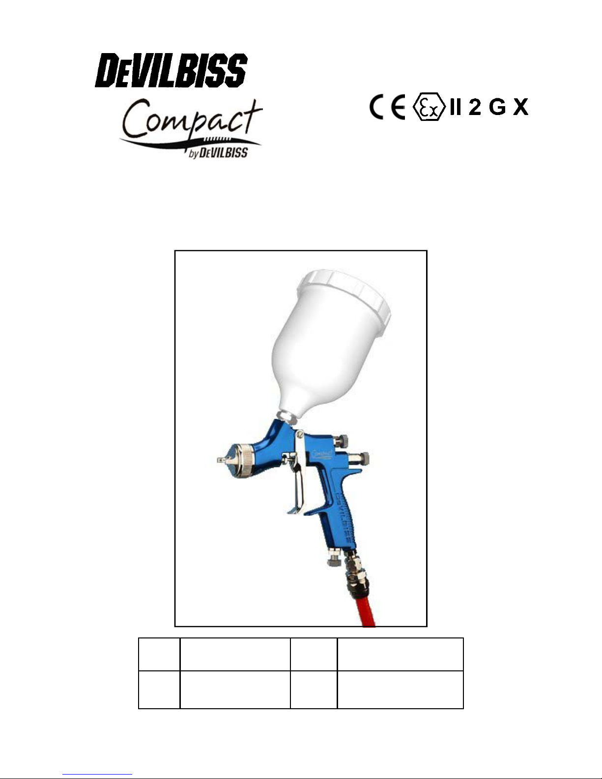
Operation Manual
COMPACT – Gravity Feed Spraygun
Important
Read and follow all instructions and Safety Precautions before using this
equipment
Description
The Compact Gravity feed Spraygun Kit complies to ATEX regulations 94/9/EC, protection
level;
Important: : These Sprayguns are suitable for use with both waterbased and solvent based
coating materials. The design uses EPA compliant (Devilbiss Trans-Tech®) and HVLP
atomising technology to reduce overspray and improve coating efficiency. These guns are not
designed for use with highly corrosive and/or abrasive materials and if used with such materials
it must be expected that the need for cleaning and/or replacement of parts will be increased. If
there is any doubt regarding the suitability of a specific material contact your local Distributor or
ITW Finishing direct.
II 2 G X, Suitable for use in Zones 1 and 2
Model Part Number
Example: COM-G510B-16
Aircap Fluid nozzle size
(16 = 1,6 mm)
Gunbody Finish
B= Blue Anodised
EC Declaration of Conformity
We: ITW Finishing UK, Ringwood Rd, Bournemouth, Dorset, BH11 9LH, UK, as the
manufacturer of the Spraygun model Compact, declare, under our sole responsibility, that the
equipment to which this document relates is in conformity with the following standards or other
normative documents:
BS EN 292-1 PARTS 1 & 2: 1991, BS EN 1953: 1999; and thereby conform to the
protection requirements of Council Directive 98/37/EC relating to Machinery Safety Directive,
and;
EN 13463-1:2001, council Directive 94/9/EC relating to Equipment and Protective
Systems intended for use in Potentially Explosive Atmospheres protection level II 2 G X.
This product complies with the requirements of the EPA guidelines, PG6/34,PG6/20 and
PG6/23. Achieving transfer efficiency in excess of 65%.
ITW Finishing Systems and Products reserve the right to modify equipment specification without
prior notice.
© 2005 ITW Finishing Systems and Products
2
B. Holt, General Manager
30th June 2003
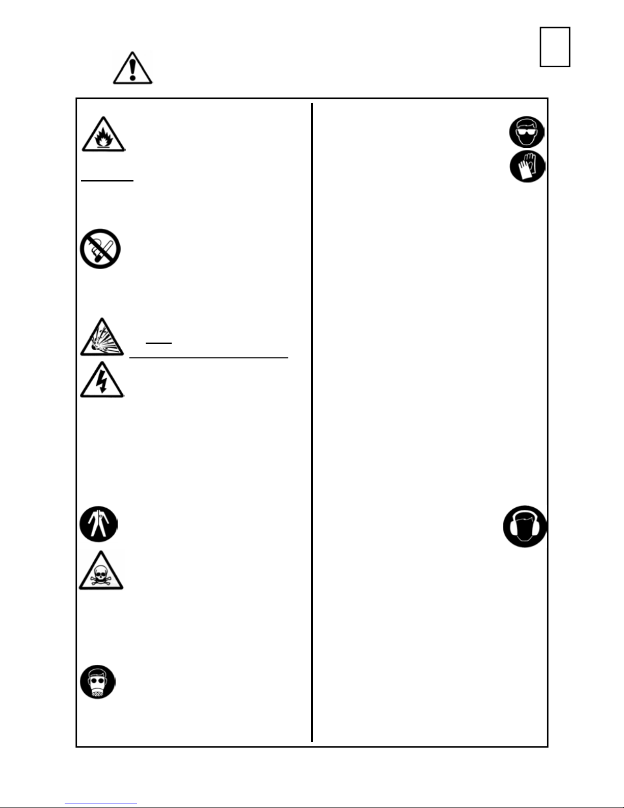
SAFETY WARNINGS
EE
Fire and explosion
Solvents and coating materials
can be highly flammable or
combustible when sprayed.
ALWAYS refer to the coating material
suppliers instructions and COSHH
sheets before using this equipment
Users must comply with all local
and national codes of practice
and insurance company
requirements governing
ventilation, fire precautions,
operation and house-keeping of working
areas
This equipment, as supplied,
is NOT
Halogenated Hydrocarbons
Static Electricity can be
generated by fluid and/or air
passing through hoses, by the
spraying process and by cleaning nonconductive parts with cloths. To prevent
ignition sources from static discharges,
earth continuity must be maintained to
the spraygun and other metallic
equipment used. It is essential to use
conductive air and/or fluid hoses.
suitable for use with
.
Always wear eye protection when
spraying or cleaning the spraygun
Gloves must be worn when
spraying or cleaning the
equipment
Training – Personnel should be given
adequate training in the safe use of
spraying equipment.
Misuse
Never aim a spraygun at any part of the
body
Never exceed the max. recommended
safe working pressure for the equipment
The fitting of non-recommended or nonoriginal spares may create hazards
Before cleaning or maintenance, all
pressure must be isolated and relieved
from the equipment
The product should be cleaned using a
gun washing machine. However, this
equipment should not be left inside gun
washing machines for prolonged periods
of time.
Noise Levels
Personal Protective
Equipment
Toxic vapours – When sprayed,
certain materials may be
poisonous, create irritation or be
otherwise harmful to health.
Always read all labels and safety data
sheets for the material before spraying
and follow any recommendations. If In
Doubt, Contact Your Material Supplier
The use of respiratory protective
equipment is recommended at all
times. The type of equipment
must be compatible with the material
being sprayed.
The A-weighted sound level of
sprayguns may exceed 85 dB
(A) depending on the set-up
being used. Details of actual
noise levels are available on request. It is
recommended that ear protection is worn
at all times when spraying.
Operating
Spray Equipment using high pressures
may be subject to recoil forces. Under
certain circumstances, such forces could
result in repetitive strain injury to the
operator.
3
© 2005 ITW Finishing Systems and Products

EE
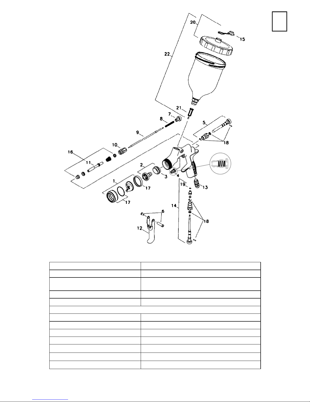
Parts List
Ref. No Description Part Number Qty Options
1
+ 2 Nozzle SP-200S-**-K 1
+ 3 Separator SP-626-K5 5
+ 4 Packing GTI-445-K2 2
5 Spreader Valve SP-403-K 1
6 Stud and Screw GTI-408-K5 5
7 Needle Adjusting Screw SP-614-K 1
+ 8 Spring SP-622-K5 1
+ 9 Needle SP-300S-**-K 1
10 Airvalve housing + seal SP-612-K 1
+ 11 Spindle - 1
12 Trigger SP-617-K 1
Air Cap/Retaining ring
COM-510
SP-100-***-K 1
510, 505
e.g *** = 505
12,13,16,18,20
e.g ** =16 =1.6 mm
12,13,16,18,20
e.g ** =16 =1.6 mm
13 Connector SP-611-K 1
14 Airflow Valve SP-402-K 1
15 Drip Check Lid kit of 5 GFC-2-K5 1
+ 16 Air Valve Service Kit SPK-101-K 1
17 Retaining Ring and Seals SPK-102-K 1
18 Spreader/ Cheater Service Kit GTI-428-K5 5
19 Circlip 25746-007-K5 5
20 Cup Lid GFC-402 1
21 Filter KGP-5 1
22 1/2 Ltr Gravity Cup Kit GFC-501 1
23 Air Valve assembly Tool 1
24 Spanner SPN-5 1
Spraygun Service Kit
(parts included marked + )
SPK-401-** 1
12, 13,16,18,20
e.g ** =16 =1.6 mm
© 2005 ITW Finishing Systems and Products
4
Patent No 2372465 (GB)
EE
Air supply connection - Universal 1/4“ BSP and NPS
Maximum static Air inlet pressure - P
Nominal gun Air inlet pressure -
with gun triggered
Maximum Service temperature 40°C
Gun Weight - 583 g
Gun body Anodised Aluminium
Nozzle Stainless Steel
Needle Stainless Steel
Fluid Inlet Stainless Steel / PTFE
Trigger Nickel Plated Steel
Cup Acetal (Anti-static)
Cup Lid Acetal (Anti-static)
Specification
= 12 bar (175 psi)
1
2. bar (29 psi) 510 Trans-Tech Air Cap
1.4 bar (20 psi) 505 HVLP Air Cap
Materials of Construction
5
© 2005 ITW Finishing Systems and Products
EE
Installation
Important: To ensure that this equipment
reaches you in first class condition,
protective coatings have been used.
Flush the equipment through with a
suitable solvent before use.
1. Attach air hose to connector (13).
Recommended hose size 8 mm bore.
The hose must be conductive and
electrical bond from the spraygun to
Operation
1. Mix coating material to manufacturers
instructions.
2. Fill the cup with the required amount
of material. Fill to no more than 25mm
(1“) from the top of the cup. DO NOT
OVERFILL.
3. Attach Cup Lid.
4. Turn needle adjusting screw (7)
clockwise to prevent movement.
5. Turn spreader valve (5) counterclockwise to fully open.
6. Adjust inlet air pressure (For
recommended figures see
Specifications) at the gun inlet with the
gun triggered. (pressure gauge
attachment shown under Accessories
is recommended for this).
7. Turn needle adjusting screw counter
clockwise until first thread shows.
8. Test spray. If the finish is too dry
reduce airflow by reducing air inlet
earth should be checked with an
ohmeter. A resistance of less than
106 Ohms is recommended.
2. Air supply should be filtered and
regulated.
3. Attach Cup assembly (22) by
screwing into the Fluid Inlet of the
spraygun. Tighen when fully home.
pressure or by the Airflow Valve (14).
Screw the Adjusting Knob (14) in to
reduce pressure.
9. If finish is too wet reduce fluid flow by
turning needle screw (7) clockwise. If
atomisation is too coarse, increase
inlet air pressure. If too fine reduce
inlet pressure.
10. The pattern size can be reduced by
turning adjusting valve (5) clockwise.
11. Hold gun perpendicular to surface
being sprayed. Arcing or tilting may
result in uneven coating.
12. The recommended spray distance is
150-200 mm (6”-8”).
13. Spray edges first. Overlap each stroke
a minimum of 50%. Move gun at a
constant speed.
14. Always turn off air supply and relieve
pressure when gun is not in use.
1. Turn off air and relieve pressure in
the supply lines, or if using QD
system, disconnect from airline.
2. Remove Cup Lid (20)and empty
coating material into a suitable
container. Clean the gun and cup,
preferably in a gun wash machine.
Clean the cup.
3. Check the breather hole in the Lid
© 2005 ITW Finishing Systems and Products
Preventative Maintenance
and the Drip Check Lid is not
blocked.
4. Remove air cap (1) and clean. If any
of the holes in the cap are blocked
with coating material use a toothpick
to clean. Never use metal wire which
could damage the cap and produce
distorted spray patterns
5. Ensure the tip of the nozzle (2) is
6
clean and free from damage. Build
up of dried paint can distort the
spray pattern.
Replacement of Parts
6. Lubrication – stud/screw (6), needle
(9) and air valve (11) should be
oiled each day.
EE
Nozzle (2) and Needle (9) – Remove
parts in the following order: 7, 8, 9, 1
and 2. Replace any worn or damaged
parts and re-assemble in reverse order.
Recommended tightening torque for
nozzle (2) 9.5-12 Nm (80-100 lbf in).
Packing – Remove parts 7, 8, 9.
Unscrew cartridge (4). Fit new cartridge
finger tight. Re-assemble parts 9, 8,
and 7 and tighten cartridge (4) with
spanner sufficient to seal but to allow
free movement of needle. Lubricate
with gun oil.
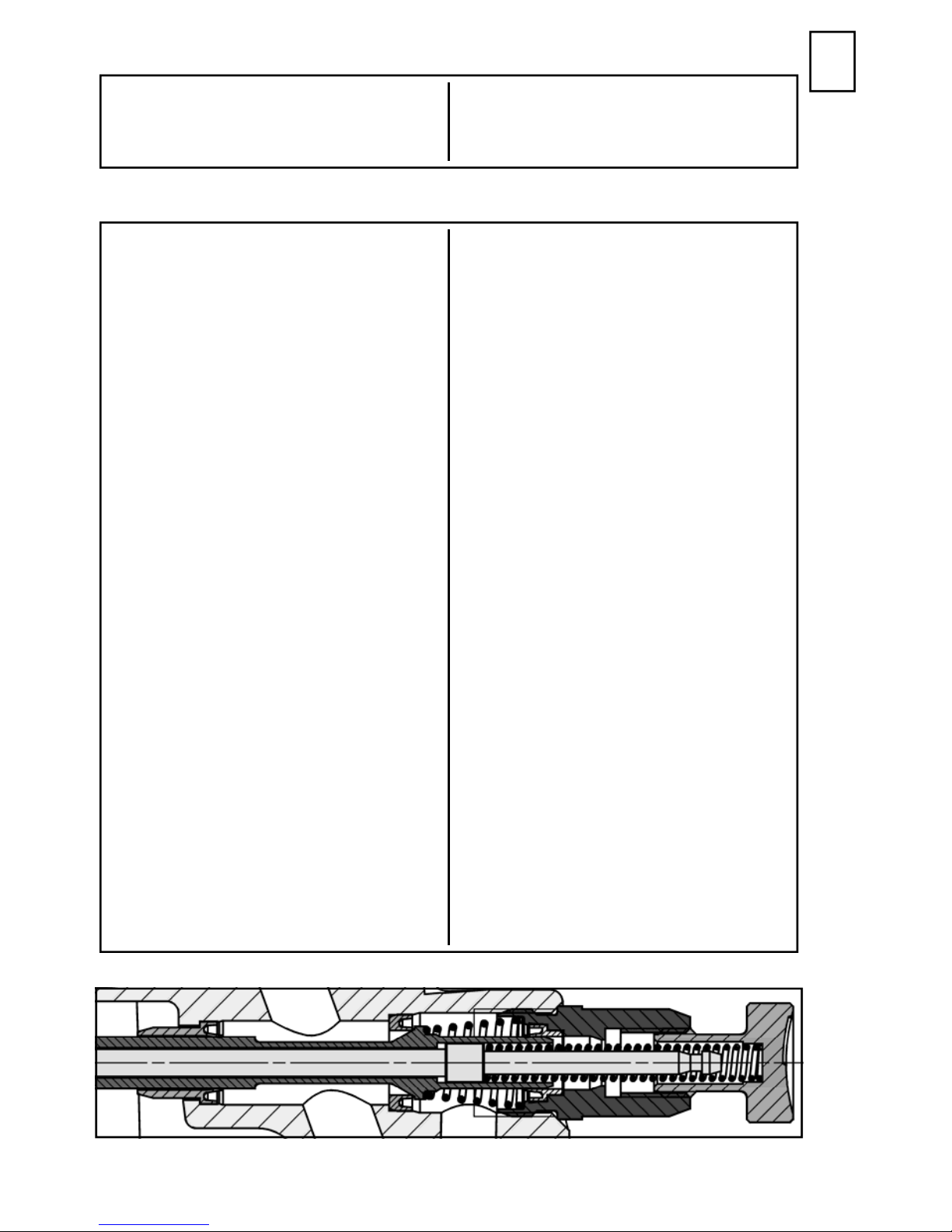
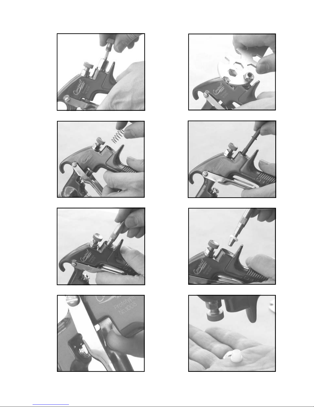
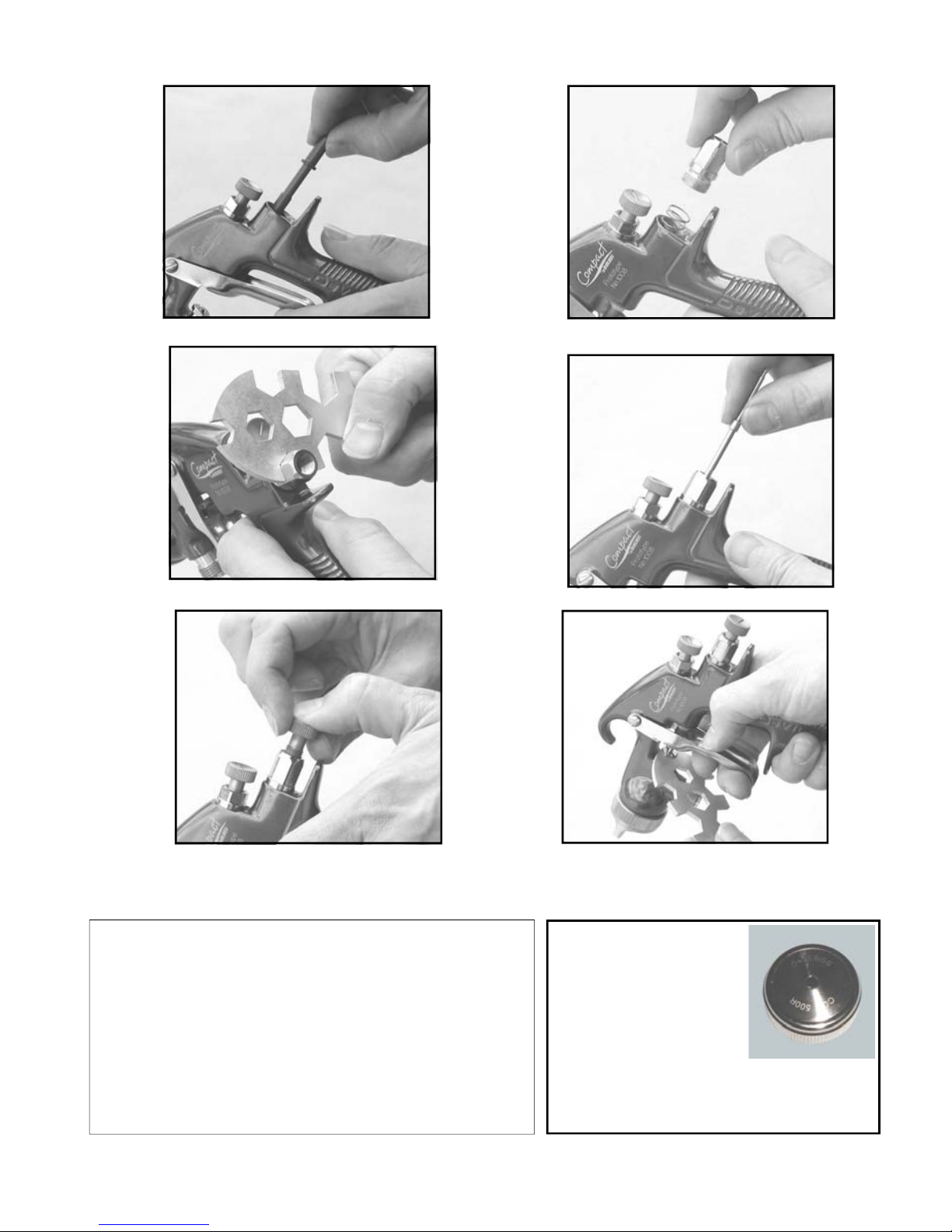
Air Valve Seal Kit (16) - (Refer to
photos 1 to 28 and fig 2)
1. Remove Adjusting Knob (7), Spring
(8), and Needle (9).
2. Loosen Housing (10).
3. Remove Housing (10) and Airvalve
Spring.
4. Remove Valve (11).
5. Using Service Tool SPN-7, engage
groove behind the Valve Seat.
6. Remove Valve Seat.
7. Push out the Front Airvalve Seal
with a finger.
8. Turn the Gun upside down and let
the Seal fall out.
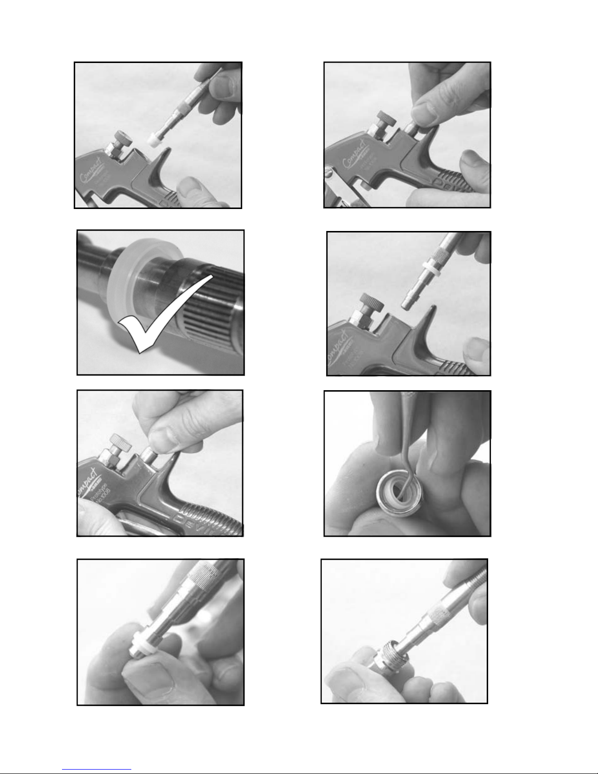
9. Fit New Front Seal to Service Tool.
10. Fit new Seal to gunbody and press
firmly to ensure Seal is engaged.
11. Fit New Valve Seat to Service Tool.
Groove must face outwards.
12. Fit Valve Seat to Gunbody.
13. Remove Rear Airvalve Seal from
housing (10) with a hooked
instrument.
14. Fit new Seal to Service Tool.
15. Fit Seal to Housing (10).
16. Replace Valve (11).
17. Replace Valve Spring and screw in
Housing (10).
18. Tighten Housing.
19. Fit Needle (9).
20. Fit Spring (8) and Knob (7).
21. Adjust Needle Packing (4) with
Spanner sufficient to seal but to
allow free movement of needle.
Lubricate with gun oil.
Spreader valve (5) – Caution: always
ensure that the valve is in the fully open
position by turning screw fully counterclockwise before fitting to body.
Air cap / Nozzle Selection
Refer to coating material manufacturers
recommendations or ITW Finishing UK
Website:
www.itweuropeanfinishing.com
FIG 2
7
© 2005 ITW Finishing Systems and Products
1 2
3 4
5 6
7 8
© 2005 ITW Finishing Systems and Products
8
9 10
11
12
11a
13
14
9
15
© 2005 ITW Finishing Systems and Products
16
17
18
20
19
21
Spanner – order SPN-5
Cleaning Brush – order 4900-5-1-K3
Regulator/Gauge Attachment - order HAV-501-B
Pressure gauge Attachment – order GA-515
Gun Mounted Regulator – order DVR-501
Spraygun Lubricant - order GL-1-K10
© 2005 ITW Finishing Systems and Products
Accessories
Roundspray Aircap -
COM-500R
HVLP Mode - Air Inlet
Pressure = 1.0 Bar
(14.5 PSI)
Tanstech Mode – Air
10
Inlet Pressure = 2 bar
(29 PSI)
Approx Spot Size = Ø50mm

DD
Betriebsanleitung
COMPACT – Fließbecher-Spritzpistole
Wichtig
Bitte lesen und befolgen Sie alle Anweisungen und Sicherheitshinweise,
bevor Sie das Gerät in Betrieb nehmen
Beschreibung
Diese Spritzpistole kann sowohl mit wasserlöslichen als auch mit auf Lösungsmitteln basierenden
Beschichtungsstoffen verwendet werden. Bei der Bauart wird eine EPA-gemäße Zerstäubungstechnologie (Devilbiss Trans-Tech® oder HVLP) eingesetzt, um den Farbnebel zu verringern und
den Auftragswirkungsgrad zu verbessern. Düsen und Nadeln sind aus rostfreiem Stahl.
Die Compact Fließbecher-Spritzpistole ist gemäß Richtlinie ATEX 94/9/EG, Schutzstufe II 2 G X,
zugelassen und kann in den Zonen 1 und 2 eingesetzt werden.
Wichtig: Diese Spritzpistolen sind nicht für den Einsatz mit stark korrosiven und/oder abreibenden
Materialien geeignet. Bei Einsatz mit solchen Stoffen muss davon ausgegangen werden, dass der
Aufwand für die Reinigung und/oder der Bedarf an Ersatzteilen steigt. Sollte es irgendwelche
Zweifel geben, ob ein bestimmtes Material geeignet ist, wenden Sie sich bitte an Ihren örtlichen
Händler oder direkt an ITW Oberflächentechnik.
Modell-Teilenummer
Beispiel: COM-G510B-16
Luftkappe Größe der Farbdüse
Wir: ITW Finishing UK, Ringwood Rd, Bournemouth, Dorset, BH11 9LH, UK erklären
eigenverantwortlich als Hersteller des Spritzpistolenmodells COMPACT, dass das Gerät, auf
das sich dieses Dokument bezieht, die folgenden Richtlinien oder Normendokumente einhält:
BS EN 292-1 TEILE 1 & 2: 1991, BS EN 1953:1999.
Daher halten diese Geräte die Schutzanforderungen der folgenden Vorschriften ein: Richtlinie
des EU-Rates 89/37/EWG zur Maschinenrichtlinie und EN 13463-1:2001, Richtlinie des EURates 94/9/EG zu Geräte und Schutzsysteme, die für den Einsatz in potenziell explosiven
Umgebungen eingesetzt werden, Schutzstufe II 2 G X.
Diese Spritzpistole hält auch die EPA-Richtlinien PG6/34, PG6/20 und PG6/23 ein.
Übertragungseffizienzdokumente werden auf Anfrage bereitgestellt.
(Nr. 510 = Trans-Tech / Nr. 505 = HVLP) (16 = 1,6 mm)
EG-Konformitätserklärung
ITW Finishing Systems and Products behält sich das Recht vor, die technischen Daten der
Geräte ohne vorherige Benachrichtigung zu ändern.
11
B. Holt, General Manager 30/6/03
© 2005 ITW Finishing Systems and Products

DD
SICHERHEITSHINWEISE
Feuer und Explosionen
Lösemittel und Beschichtungsstoffe
können leicht entflammbar oder brennbar
sein, wenn sie verspritzt oder versprüht werden.
Schlagen Sie IMMER die Anweisungen des
Herstellers für den Beschichtungsstoff und
die COSHH-Blätter nach, bevor Sie diese
Geräte benutzen.
Die Anwender müssen sämtliche örtlichen
und nationalen Arbeitsvorschriften und
Anforderungen der Behörden und Berufsgenossenschaften erfüllen, und zwar hinsichtlich
Belüftung, Brandbekämpfung, Betrieb und
allgemeine Praxis am Arbeitsplatz.
Diese Geräte sind in ihrem gelieferten
Zustand NICHT dazu geeignet, mit
halogenisiertem Kohlenwasserstoff
verwendet zu werden.
Beim Durchfluss von Flüssigkeiten und/
oder Luft durch Schläuche, beim Spritzlackieren und beim Reinigen von nicht-
leitenden Teilen mit Lappen können
statische Aufladungen entstehen. Die
Spritzpistole und alle eingesetzten Geräte aus
Metall müssen ständig geerdet sein, um
Zündquellen von statischen Entladungen zu
vermeiden. Es müssen auf jeden Fall leitende
Luft- und/oder Materialschläuche verwendet
werden.
Schutzausrüstung für das
Personal
Giftige Dämpfe – Bestimmte Materialien
sind giftig, können Ausschläge verursachen oder auf andere Weise gesund-
heitlich schädigend sein. Lesen Sie bitte
immer alle Schilder und Datenblätter für das
Material durch, bevor Sie mit dem Lackieren
beginnen; befolgen Sie alle Empfehlungen. Falls
Zweifel bestehen, wenden Sie sich bitte an
Ihren Materiallieferanten.
Es wird empfohlen, jederzeit Atemschutzgeräte zu verwenden. Die
Schutzstufe der Geräte muss dem
jeweils verarbeiteten Material ent-
sprechen.
Augenschutz muss immer beim
Lackieren oder bei der Reinigung
getragen werden.
Handschuhe müssen immer beim
Lackieren oder bei der Reinigung
getragen werden.
Training – Das Personal muss für den gefahrlosen Einsatz der Spritzgeräte entsprechend
ausgebildet werden.
Missbrauch
Eine Spritzpistole darf auf keinen Fall auf
irgendeinen Körperteil gerichtet werden.
Der maximale, empfohlene, sichere Arbeitsdruck
für die Geräte darf niemals überschritten werden.
Der Einbau von Ersatzteilen, die nicht empfohlen
werden oder nicht original sind, könnte ein
Gefahrenrisiko darstellen.
Vor der Reinigung oder einer Wartung muss die
Druckluftversorgung abgetrennt werden; der
Restdruck muss in den Geräten abgebaut
werden.
Spritzgeräte sollten mit einer Wascheinrichtung
für Spritzgeräte gereinigt werden. Die Geräte
sollten jedoch nicht über lange Zeiträume in der
Wascheinrichtung belassen werden.
Geräuschpegel
Der A-gewichtete Geräuschpegel von
Spritzpistolen kann 85 dB (A) überschreiten, abhängig von der verwendeten Luftkappe. Einzelheiten über die
tatsächlichen Geräuschpegel sind auf
Anfrage erhältlich. Es wird empfohlen, beim
Spritzlackieren immer einen Gehörschutz zu
tragen.
Betrieb
Spritzgeräte, die mit hohem Druck arbeiten,
können Rückstöße erzeugen. In bestimmten
Situationen können diese Rückstöße Überlastungsschäden beim Bediener verursachen.
© 2005 ITW Finishing Systems and Products
12

DD
Stückliste
Ref. Nr. Beschreibung Teilenummer Stück
1
2* Düse SP-200S-**-K 1
3* Luftverteiler (5 Stück) SP-626-K5 1
4* Farbnadelpackung (2 Stück) GTI-445-K2 1
5 Strahlregulierventil SP-403-K 1
6 Bolzen mit Schraube (5 Stück) GTI-408-K5 1
7 Farbnadelstellschraube SP-614-K 1
8* Feder (5 Stück) SP-622-K5 1
9* Farbnadel SP-300S-**-K 1
10 Ventilgehäuse SP-612-K 1
11* Spindel - 1
12 Fingerabzug SP-617-K 1
13 Lufteinlassnippel SP-611-K 1
Luftkappe mit Haltering (Trans-Tech)
Luftkappe mit Haltering (HVLP)
SP-100-510-K
SP-100-505-K
1
14 Luftfeinregulierventil SP-402-K 1
15 Tropfsperrclip (5 Stück) GFC-2-K5 1
16* Dichtungen und Feder für Luftventil SPK-101-K 1
17 Luftkappenhaltering mit Dichtungen SPK-102-K 1
18* Dichtung, Stift und Sprengring (5 Stück) GTI-428-K5 2
19 Sprengring (5 Stück) 25746-007-K5 1
20 Becherdeckel GFC-402 2
21 Feinfilter (5 Stück) KPG-5-K5 1
22 Fließbecher 0,6 ltr. kpl. GFC-501 1
* Teile im Service Set enthalten. Bestell-Nr. SPK-401-...-K (bitte Düsengröße angeben)
** verfügbare Größen: 0.85, 1.0, 1.1, 1.2, 1.3, 1.4, 1.6, 1.8, 2.0, 2.2 mm
13
© 2005 ITW Finishing Systems and Products

DD
Patentnr. 2372465(GB)
Lufteingang -
Maximaler, statischer Einlassluftdruck -
Nominaler Pistolendruck bei
abgezogener Pistole -
Maximale Einsatztemperatur -
Pistolengewicht inkl. Becher -
Pistolenkörper Eloxiertes Aluminium
Düse Rostfreier Stahl
Farbnadel Rostfreier Stahl
Fließbecher Acetal und rostfreier Stahl
© 2005 ITW Finishing Systems and Products
Technische Daten
Universal
= 12 bar (175 psi)
P
1
2. bar (29 psi)
1.4 bar (20 psi)
40°C
583 g
Fertigungsmaterialien
14
1
/4“ BSP and NPS
bei Trans-Tech
bei HVLP

Inbetriebnahme
DD
Wichtig: Um zu gewährleisten, dass Sie die
Geräte in erstklassigem Zustand erhalten,
wurden sie mit einer Schutzschicht überzogen.
Spülen Sie die Geräte vor dem Gebrauch
mit einem geeigneten Lösungsmittel durch.
1. Schließen Sie den Luftschlauch an den
Lufteingang (13) an. Ein Schlauch mit
einem Innendurchmesser von mindestens
8 mm wird empfohlen. Der Schlauch muss
Betrieb
1. Die Beschichtungsstoffe laut Herstellerangaben mischen.
2. Den Becher mit der gewünschten
Materialmenge füllen. Nicht mehr als bis
25 mm unter den Rand des Bechers
füllen.
3. Setzen Sie den Becherdeckel auf.
4. Drehen Sie die Farbnadelstellschraube (7)
im Uhrzeigersinn, um eine Bewegung der
Farbnadel zu vermeiden.
5. Drehen Sie das Strahlregulierventil (5)
gegen den Uhrzeigersinn ganz auf.
6. Stellen sie den Einlassluftdruck am
Pistoleneinlass bei abgezogener Pistole
ein (die empfohlenen Werte finden Sie
in den technischen Angaben).
der Einsatz des Luftregulierventils mit
Manometer (HAV-501-B) empfohlen.
7. Drehen Sie die Farbnadelstellschraube (7)
gegen den Uhrzeigersinn, bis der erste
Gewindegang sichtbar ist.
8. Spritztest. Wenn der Auftrag zu trocken ist,
reduzieren Sie die Luftzufuhr durch Verringern des Einlassluftdrucks oder durch
Dazu wird
elektrisch leitend sein. Prüfen Sie die
elektrische Leitfähigkeit von der Spritzpistole zur Erde mit einem Ohmmeter. Der
Widerstand sollte unter 106 Ω liegen.
2. Die Luftzufuhr sollte gefiltert und reguliert
sein.
3. Schrauben Sie den Fließbecher in den
Materialeingang und ziehen ihn mit einem
Schraubenschlüssel fest.
Drehen des Luftfeinregulierventils (14) im
Uhrzeigersinn.
9. Wenn der Auftrag zu nass ausfällt, reduzieren Sie die Materialzufuhr durch Drehen
der Farbnadelstellschraube (7) im Uhrzeigersinn. Wenn die Zerstäubung zu grob
erfolgt, erhöhen Sie den Einlassluftdruck.
Ist sie zu fein, reduzieren Sie den Einlassluftdruck.
10. Der Spritzstrahl kann durch Drehen des
Strahlregulierventils (5) eingestellt werden.
11. Pistole senkrecht zur zu spritzenden
Fläche führen. Ein Kippen oder Neigen
kann zu ungleichmäßigen Beschichtungsstärken führen.
12. Der empfohlene Spritzabstand beträgt
150 - 200 mm.
13. Die Ränder zuerst spritzen. Jede Bahn um
mindestens 50 % überlappen. Die Pistole
mit gleichförmiger Geschwindigkeit bewegen.
14. Wenn die Pistole nicht verwendet wird, soll
die Luftversorgung immer abgedreht und
der Druck abgelassen werden.
1. Drehen Sie die Luftversorgung ab und
entlüften Sie den Druck aus den Leitungen.
Wenn ein Schnellwechsel-System verwendet
wird, von der Luftversorgung abhängen.
2. Entleeren Sie das Beschichtungsmaterial in
einen geeigneten Behälter. Die Pistole sollte
in einem Pistolenwaschautomaten gereinigt
werden.
3. WICHTIG: Der Fließbecher darf nicht mit
einem trockenen Lappen oder mit trockenem
Papier gereinigt oder abgewischt werden.
Das Wischen kann eine statische Aufladung
bewirken, die bei einem Entladen zu einem
geerdeten Objekt einen Zündfunken
Vorbeugende Wartung
verursachen kann, der zu einem Entzünden
der Lösungsmitteldämpfe führen kann.
Verwenden Sie nur feuchte Lappen oder
antistatische Tücher, wenn Sie in einem
Gefahrenbereich Reinigungsarbeiten ausführen müssen.
4. Sorgen Sie dafür, dass die Spitze der
Düse (2) sauber und nicht beschädigt ist.
Ablagerungen aus getrocknetem Lack
können den Spritzstrahl ebenfalls verfälschen.
5. Schmierung: Bolzen/Schraube (6), Farbnadel
(9) und Luftventil (11) sollten jeden Tag
eingeölt werden.
15
© 2005 ITW Finishing Systems and Products

DD
Austausch von Teilen
Düse (2) und Farbnadel (9) – Teile in der
folgenden Reihenfolge ausbauen: 7, 8, 9, 1
und 2. Alle abgenützten und beschädigten
Teile ersetzten und in umgekehrter
Reihenfolge zusammenbauen. Empfohlenes
Drehmoment für die Düse (2) 9,5 - 12 Nm.
Farbnadelpackung (4) – Teile 7, 8 und 9
ausbauen. Farbnadelpackung (4) abschrauben. Neue Farbnadelpackung handfest
einschrauben. Teile 9, 8 und 7 einbauen und
Farbnadelpackung (4) mit dem Pistolenschlüssel ausreichend festziehen, damit sie
dicht sitzt; die Farbnadel muss sich jedoch frei
bewegen lassen.
Luftventil und Dichtungen (11/16) - siehe
Fotos 1 bis 21 und Abbildung 2
1. Teile 7,8 und 9 ausbauen.
2. Ventilgehäuse (10) entfernen.
3. Ventilfeder herausnehmen.
4. Spindel (11) aus dem Pistolenkörper
nehmen.
5. Verwenden Sie das Werkzeug SPN-7 und
führen es in den Pistolenkörper ein.
6. Nehmen Sie nun den Ventilsitz heraus.
7. Drücken Sie die vordere Luftventildichtung
mit einem Finger heraus.
8. Drehen Sie die Spritzpistole um und
lassen Sie die Dichtung herausfallen.
9. Setzen Sie eine neue Dichtung vorne auf
das Werkzeug SPN-7.
10. Drücken Sie nun die Dichtung in den
Pistolenkörper ein.
11. Setzen Sie einen neuen Ventilsitz auf das
Werkzeug.
12. Setzen Sie den Ventilsitz im Pistolenkörper
ein.
13. Entfernen Sie die hintere Luftventildichtung
aus dem Ventilgehäuse (10).
14. Setzen Sie eine neue Dichtung auf das
Werkzeug.
15. Setzen Sie die Dichtung in das Ventil-
gehäuse (10) ein.
16. Ersetzen Sie die Spindel (11).
17. Wechseln Sie die Ventilfeder aus und
schrauben Sie das Ventilgehäuse (10)
ein.
18. Ziehen Sie das Ventilgehäuse fest.
19. Setzen Sie die Farbnadel (9) ein.
20. Montieren Sie die Feder (8) und die
Farbnadelstellschraube (7).
21. Stellen Sie die Farbnadelpackung (4) mit
einem Pistolenschlüssel so ein, dass sie
abdichtet, die Farbnadel sich jedoch frei
bewegen lässt. Ölen Sie mit Pistolenöl
(6-428) ein.
Strahlregulierventil (5) – Vorsicht: Sorgen
Sie dafür, dass das Ventil immer voll geöffnet
ist, bevor es im Pistolenkörper montiert wird;
dazu drehen Sie die Schraube ganz gegen
den Uhrzeigersinn.
Luftkappen– und Düsenauswahl
Schlagen Sie die Empfehlungen vom
Hersteller für den Beschichtungsstoff nach
oder schauen Sie auf den Internetseiten von
ITW Oberflächentechnik nach:
www.itw-finishing.de
Abb. 2
© 2005 ITW Finishing Systems and Products
16

1 2
3 4
5 6
7 8
17
© 2005 ITW Finishing Systems and Products

9 10
11
12
11a
13
14
© 2005 ITW Finishing Systems and Products
15
18

16
17
18
20
19
21
19
© 2005 ITW Finishing Systems and Products

Zubehör
Pistolenschlüssel – Bestell-Nr. SPN-5
Reinigungsbürste (3 Stück) – Bestell-Nr. 4900-5-1-K3
Service Set – Bestell-Nr. SPK-401-..-K
Filter für Lufteingang – Bestell Nr. HAF-507
Luftregulierventil mit Manometer – Bestell-Nr. HAV-501-B
Mess - und Mischbecher (50 Stück) – Bestell Nr. MC-1-K50
Viskositäts-Messbecher DIN4 (2 Stück) - Bestell-Nr. 7000-114-K2
Wartungsöl, silikonfrei (Flasche mit 75 ml) – Bestell-Nr. 6-428
Schmierfett, silikonfrei (Tube mit 50 g) – Bestell-Nr. AGMD-010
Handreinigungstücher SCRUBS (6 Eimer à 72 Tücher) - Bestell-Nr. 192218-K6
Alu-Becher 1 ltr. - Bestell-Nr. GFC-502
Pistolenständer für 3 Fließbecherpistolen - Bestell-Nr. GGS-1
(bitte Düsengröße angeben)
© 2005 ITW Finishing Systems and Products
20

FF
Manuel d'utilisation
COMPACT – Pistolet à gravité
Lire attentivement toutes les instructions et suivre les Consignes de
sécurité avant d'utiliser ce matériel
Description
Le kit pistolet à gravité Compact est conforme à la réglementation ATEX 94/9/CE, niveau
de protection :
II 2 G X et peut être utilisé dans les Zones 1 et 2
Important :
base de solvant. La conception fait appel à une technologie de pulvérisation conforme aux
règles EPA (Devilbiss Trans-Tech®) et HVLP, qui réduit les effets de brouillard et améliore
le rendement en application.
Ces pistolets ne sont pas conçus pour l’utilisation avec des produits fortement corrosifs et/
ou abrasifs. S’ils sont utilisés avec de tels produits, ils devront être nettoyés et/ou les
pièces devront être remplacées plus souvent. S'il y a le moindre doute en ce qui concerne le
caractère approprié d'un produit spécifique, contactez votre distributeur local ou ITW Finishing
directement.
Ces pistolets peuvent être utilisés avec des produits à base aqueuse et à
Numéro de référence du modèle
Exemple : COM-G510B-16
Chapeau d'air Dimension de la buse
(16 = 1,6 mm)
Finition du corps du pistolet
B= Bleu anodisé
Déclaration de conformité CE
Nous : ITW Finishing UK, Ringwood Rd, Bournemouth, Dorset, BH11 9LH, RoyaumeUni, en tant que fabricant du Pistolet Compact, déclarons, sous notre entière
responsibilité, que le matériel auquel ce document se rapporte est conforme aux normes
suivantes ou à d'autres documents normatifs :
BS EN 292-1 PARTIES 1& 2: 1991, BS EN 1953:1999 ; et est donc conforme aux
exigences de protection de la Directive du conseil 98/37/CEE relative à la Directive sur la
sécurité des machines et de
EN 13463-1:2001, la Directive du conseil 94/9/CE relative aux Équipements et systèmes
de protection prévus pour les atmosphères potentiellement explosives, niveau de
protection II 2 G X.
Ce produit est aussi conforme aux exigences des directives de l'EPA, PG6/34, PG6/20
et PG6/23. Rendement de transfert supérieur à 65 %.
ITW Finishing Systems and Products se réserve le droit de modifier les spécifications des équipements sans préavis
.
21
B. Holt, Directeur général
30/6/2003
© 2005 ITW Finishing Systems and Products

CONSIGNES DE SECURITE
FF
Incendie et explosion
Les solvants et produits de
revêtement peuvent être
extrêmement inflammables ou combustibles
lorsqu'ils sont pulvérisés. Se reporter
TOUJOURS
fournisseurs de produits et aux fiches
COSHH avant d'utiliser le pistolet.
ventilation, les précautions à prendre contre
l'incendie, le fonctionnement et la surveillance
des lieux de travail.
Ce pistolet, tel qu'il est fourni, n'est PAS
prévu pour les hydrocarbures halogénés.
d'inflammation avec des décharges statiques,
la continuité à la terre doit être maintenue
avec le pistolet et tout autre materiel
métallique utilisé. Il est essentiel d'utiliser des
flexibles d'air et/ou de liquide conducteurs.
aux instructions des
Les utilisateurs doivent se conformer
aux codes de pratique locaux et
nationaux et aux exigences des
compagnies d'assurance régissant la
De l'électricité statique peut être
produite par le liquide et/ou l'air qui
circule dans les flexibles, par le
processus de pulvérisation et par le
nettoyage de pièces nonconductrices avec des chiffons.
Pour éviter de créer des sources
Équipement de protection
individuel
Vapeurs toxiques – Lorsqu'ils sont
pulvérisés, certains produits peuvent
être toxiques, irritants ou
généralement nocifs. Toujours lire
les étiquettes et les fiches signalétiques des
produits avant de les pulvériser, et respecter
les consignes de sécurité. En cas de doute,
contacter le fournisseur du produit.
Il est recommandé d'utiliser un
appareil de protection respiratoire à
tout moment. Le type d'appareil doit
être compatible avec le produit pulvérisé
.
Toujours porter une protection
oculaire pour pulvériser ou nettoyer le
pistolet.
Porter des gants pour pulvériser ou
nettoyer le pistolet.
Formation – Le personnel doit être formé à
l'utilisation sans risque apprendre du pistolet.
Mauvaise utilisation
Ne jamais diriger le pistolet vers une
quelconque partie du corps.
Ne jamais excéder la pression de service
maximale recommandée pour le pistolet.
La pose de pièces détachées nonrecommandées ou qui ne sont pas d'origine
peut être à l'origine de risques.
Avant le nettoyage ou l'entretien, isoler et
évacuer la pression du pistolet.
Nettoyer le pistolet avec une machine
spécialement conçue à cet effet. Toutefois, ne
pas laisser le pistolet à l'intérieur de la
machine pendant une période prolongée.
Niveaux sonores
Le niveau sonore pondéré A des
pistolets de pulvérisation peu
dépasser 85 dB (A) selon la
configuration utilisée. Le détail des
niveaux sonores actuels est disponible sur
demande. Le port de protecteurs d'oreilles est
recommandé à tout moment pendant la
pulvérisation.
Utilisation
Le pistolet fonctionne sous hautes pressions
susceptibles de provoquer un effort de recul.
Dans certains cas, ces forces peuvent infliger
des microtraumatismes répétés à l’utilisateur.
© 2005 ITW Finishing Systems and Products
22

Liste de pièces
FF
Repère Description Réf Qt
é
1 Chapeau d’air/bague de retenue
COM-510
+ 2 Buse SP-200S-**-K 1 12,13,16,18,20,22
+ 3 Séparateur SP-626-K5 5
+ 4 Presse-étoupe GTI-445-K2 2
5 Valve de réglage de jet SP-403-K 1
6 Goujon et vis GTI-408-K5 5
7 Vis de réglage d'aiguille SP-614-K 1
+ 8 Ressort SP-622-K5 1
+ 9 Aiguille SP-300S-**-K 1 12,13,16,18,20,22
10 Logement de soupape d'air SP-612-K 1
+ 11 Tige - 1
12 Gâchette SP-617-K 1
SP-100-***-K 1 510, 505
Options
Ex. *** = 505
ex. ** =16 =1,6
mm
ex. ** =16 =1,6mm
13 Raccord SP-611-K 1
14 Valve de débit d’air SP-402-K 1
15 Kit couvercle antigoutte (5) GFC-2-K5 1
+ 16 Kit d'entretien de soupape d'air SPK-101-K 1
17 Bague de retenue et joints SPK-102-K 1
+ 18 Kit valve de réglage de jet/"cheater" GTI-428-K5 5
19 Circlip 25746-007-K5 5
20 Couvercle de godet GFC-402 2
21 Filtre KGP-5 1
22 Kit godet d'alimentation par gravité
(0,5 l)
23 Outil d'assemblage de soupape
d'air
24 Clé SPN-5 1
Kit d'entretien de pistolet
(pièces comprises marquées d'un
+)
GFC-501 1
1
SPK-401-** 1 12,13,16,18,20
ex. ** =16 =1,6
mm
23
© 2005 ITW Finishing Systems and Products

FF
Brevet N° 2372465(GB)
Spécifications
Raccord d’alimentation d’air -
Pression d’entrée statique d'air maximale P
Pression d’entrée d’air nominale de
pistolet gâchette actionnée
Température de service maximale - 40°C
Poids du pistolet et du godet 583 g
Matières de construction
Corps du pistolet Aluminium anodisé
Buse Acier inoxydable
Aiguille Acier inoxydable
Entrée de produit Acier inoxydable / PTFE
Gâchette Acier nickelé
Godet Acétal (Antistatique)
Couvercle de godet Acétal (Antistatique)
Universal 1/4“ BSP and NPS
= 12 bar (175 psi)
1
2. bar (29 psi) 510 Chapeau d’air Trans-Tech
1.4 bar (20 psi)
Chapeau d’air HVLP 505
© 2005 ITW Finishing Systems and Products
24

Installation
FF
Important : Des revêtements protecteurs
ont été utilisés pour que ce matériel vous
parvienne en parfait état. Rincer le matériel
avec un solvant approprié avant
utilisation.
1. Brancher le flexible d'air au raccord (13).
Le diamètre de flexible recommandé est
de 8 mm. Le flexible doit être conducteur
et la liaison électrique du pistolet à la
Fonctionnement
1. Mixer le produit selon les instructions du
fabricant.
2. Remplir le godet avec la quantité requise
de produit. Le niveau de produit doit
s'arrêter à 25 mm ou plus du haut du
godet. NE PAS REMPLIR
EXCESSIVEMENT.
3. Monter le couvercle du godet.
4. Tourner la vis de réglage de l'aiguille (7)
dans le sens horaire pour interdire tout
mouvement.
5. Tourner la valve de réglage du jet (5)
dans le sens anti-horaire pour l'ouvrir
complètement.
6. Régler la pression d'entrée d'air de
manière à obtenir 2 bar (29 psi) à
l'entrée du pistolet quand la gâchette est
actionnée. (le manomètre illustré sous la
rubrique Accessoires est recommandé à
cet effet).
7. Tourner la vis de réglage dans le sens
anti-horaire jusqu'à l'apparition du
premier filet.
8. Faire un essai de pulvérisation. Si le fini
est trop sec, réduire le débit d'air en
réduisant la pression d'entrée d'air ou
terre doit être contrôlée avec un
ohmmètre. Une résistance inférieure à
6
Ω est recommandée.
10
2. L’alimentation d’air doit être filtrée et
régulée.
3. Monter l'ensemble godet (22) en le
vissant dans le raccord d'entrée de
produit du pistolet. Le serrer quand il est
complètement engagé.
avec la valve de débit d'air (14). Serrer le
bouton de réglage (14) pour réduire la
pression.
9. Si le fini est trop humide, tourner la vis
de réglage de l’aiguille (7) dans le sens
horaire peur diminuer le débit de produit,
ou réduire la pression du produit. Si la
pulvérisation est trop grossière,
augmenter la pression d’entrée d’air. Si
elle est trop fine, réduire la pression
d’entrée.
10. La taille de la forme de pulvérisation peut
être réduite en tournant la valve de
réglage (5) dans le sens horaire.
11. Maintenir le pistolet perpendiculaire à la
surface de travail. Le revêtement risque
de ne pas être uniforme si l'on incline le
pistolet vers le haut ou le bas.
12. La distance de pulvérisation préconisée
est 150-200 mm.
13. Commencer par pulvériser les bords.
Empiéter au moins de moitié sur la
pulvérisation précédente en déplaçant le
pistolet à vitesse régulière.
14. Toujours couper l’arrivée d’air et évacuer
la pression quand le pistolet est inutilisé.
1. Couper l’arrivée d’air et évacuer la pression
des conduites d’air. Si le système QD est
utilisé, le débrancher de la conduite d’air.
2. Retirer le couvercle du godet (20) et vider le
produit dans un récipient approprié.
Nettoyer le pistolet et le godet, de
préférence dans une machine spécialement
conçue à cet effet. Nettoyer le godet.
3. S'assurer que le trou d'évent du couvercle
Entretien préventif
et du couvercle antigoutte n'est pas bouché.
4. Enlever et nettoyer le chapeau d’air (1).
Si les trous du chapeau sont bouchés
par le produit, les déboucher avec un
cure-dent. Ne jamais utiliser de fil
métallique au risque d’endommager le
chapeau et de déformer la pulvérisation.
5. Vérifier que la buse (2) est propre et en
bon état. Une accumulation de peinture
25
© 2005 ITW Finishing Systems and Products

FF
sèche risque de déformer la
pulvérisation.
6. Graissage – huiler chaque jour le
Remplacement de pièces
Buse (2) et aiguille (9) – Déposer les pièces
dans l'ordre suivant : 7, 8, 9, 1 et 2.
Remplacer les pièces usées ou
endommagées. Pour la repose, inverser
l'ordre. Le couple de serrage recommandé
de la buse (2) est 9,5-12 Nm.
Presse-étoupe – Déposer les pièces 7, 8, et
9. Dévisser la cartouche (4). Poser une
cartouche neuve et la visser à la main.
Reposer les pièces 9, 8 et 7, puis serrer la
cartouche (4) avec une clé, suffisamment
pour assurer l'étanchéité tout en permettant
à l'aiguille de bouger librement. Lubrifier à
l'huile de pistolet.
Kit joint de soupape d'air (16) – (voir les
photos 1 à 28).
1. Retirer le bouton de réglage (7), le
ressort (8) et l'aiguille (9).
2. Desserrer le logement (10).
3. Déposer le logement (10) et le ressort de
la soupape d'air.
4. Déposer la soupape (11).
5. A l'aide de l'outil d'entretien SPN-7,
engager la rainure derrière le siège de la
soupape.
6. Déposer le siège de la soupape.
7. Extraire le joint avant de la soupape d'air
en le poussant du doigt.
8. Retourner le pistolet pour faire tomber le
joint.
9. Placer un joint avant neuf sur l'outil
d'entretien.
10. Poser le joint neuf sur le corps du pistolet
goujon/la vis (6), l’aiguille (9) et la
soupape d’air (11).
et appuyer fermement dessus pour bien
l'engager.
11. Placer un siège de soupape neuf sur
l'outil d'entretien.
12. Poser le siège de soupape sur le corps
du pistolet.
13. Retirer le joint de soupape d'air arrière
du logement (10) à l'aide d'un instrument
crochu.
14. Placer un joint neuf sur l'outil d'entretien.
15. Poser le joint dans le logement (10).
16. Remettre la tige (11).
17. Reposer le ressort de soupape et visser
le logement (10).
18. Serrer le logement.
19. Monter l'aiguille (9).
20. Monter le ressort (8) et le bouton (7).
21. Régler le presse-étoupe de l'aiguille (4)
avec une clé de façon à assurer
l'étanchéité mais à ne pas gêner le
mouvement de l'aiguille. Lubrifier à l’huile
de pistolet.
Valve de réglage de jet (5) – Attention :
toujours s'assurer que la valve est en
position d'ouverture maximum en tournant la
vis à fond dans le sens anti-horaire avant la
pose sur le corps.
Sélection de chapeau d'air / buse
Se reporter aux recommandations du
fabricant du produit de revêtement ou visiter
le site Web d'ITW Finishing UK :
www.itweuropeanfinishing.com
FIG 2
© 2005 ITW Finishing Systems and Products
26

1 2
3 4
5 6
7 8
27
© 2005 ITW Finishing Systems and Products

9 10
11
12
11a
13
14
© 2005 ITW Finishing Systems and Products
15
28

16
17
18
20
19
21
29
© 2005 ITW Finishing Systems and Products

Accessoires
Clé – N° de commande SPN-5
Brosse de nettoyage – N° de commande 4900-5-1-K3
Régulateur/manomètre – Réf. HAV-501-B
Manomètre – Réf. GA-515
Régulateur monté sur pistolet – Réf. DVR-501
Lubrifiant de pistolet – Réf. GL-1-K10
Chapeau d'air jet rond - COM-500R
Mode HVLP – Pression d'entrée d'air = 1,0 bar (14,5 PSI)
Mode Transtech – Pression d'entrée d'air = 2 bar (29 PSI)
Dimension approx. du jet = Ø 50 mm
© 2005 ITW Finishing Systems and Products
30

31
© 2005 ITW Finishing Systems and Products

ITW Finishing Systems and Products
Ringwood Road,
Bournemouth,
BH11 9LH,
England.
Tel. No. (01202) 571111
Telefax No. (01202) 581940,
Website address http://www.itweuropeanfinishing.com
ITW Oberflächentechnik GmbH & Co. KG
Justus-von-Liebig-Straße 31
63128 Dietzenbach
Telefon: (06074) 403-1
Telefax: (06074) 403-300
Internet: http://www.itw-finishing.de
ITW Surfaces Et Finitions
163-171 avenue des Auréats B.P. 1453
26014 VALENCE CEDEX FRANCE
Tél. (33) 475-75-27-00
Télex 345 719F DVILBIS
Téléfax: (33) 475-75-27-99
ITW Finishing Systems and Products is a Division of ITW Ltd. Reg. Office:
Admiral House,
St Leonard’s Road,
Windsor,
Berkshire,
SL4 3BL,
UK
Registered in England: No 559693 Vat No 619 5461 24
© 2005 ITW Finishing Systems and Products
32
NOV 05
 Loading...